1
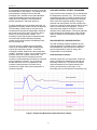
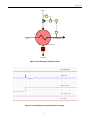
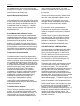
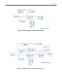
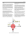
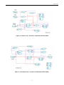
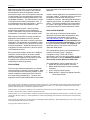
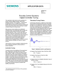
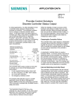
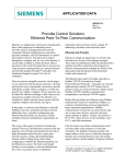
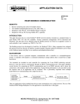
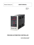
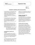
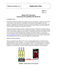
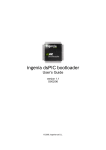
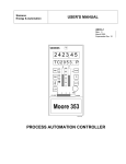
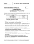
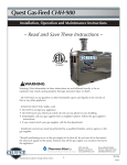
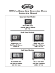
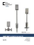
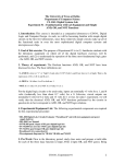
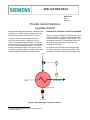
APPLICATION DATA
AD353-128
Rev 2
April 2012
Procidia Control Solutions
Cascade Control
This application data sheet describes cascade control
techniques. A cascade control configuration can be
easily developed within a Siemens 353 controller. 1
Cascade control uses a secondary controller in
conjunction with a primary controller to improve
control of the primary process variable. In cascade
control, the output of a primary controller manipulates
the setpoint of a secondary controller. This control
strategy increases the speed of the primary control
loop and is particularly useful for minimizing the effect
of load changes that disturb the primary variable.
SINGLE-LOOP CONTROL OF HEAT EXCHANGER
Figure 1 shows an example in which cascade control
would be beneficial. In this heat exchanger example,
exit temperature is the primary control variable. The
temperature controller (TC) manipulates the flow of
steam to the heat exchanger to control the exit
temperature at setpoint.
An increase in the feed flow to the heat exchanger
will cause a decrease in the exit temperature. The
temperature controller responds to this control error
Steam
TC
TT
Feed
Exit Temperature
Heat Exchanger
T
Condensate
Figure 1 Heat Exchanger Temperature Control
1
See Applications Support at the back of this publication
for a list of controllers.
AD353-128
by increasing the steam flow as required to return the
exit temperature to the setpoint. The change in feed
flow represents a change in load on the heat
exchanger and is referred to as a load disturbance.
Other load disturbances that can affect the exit
temperature are changes in feed temperature,
ambient temperature, and steam pressure.
CASCADE CONTROL OF HEAT EXCHANGER
Figure 3 shows a flow controller (FC) in cascade with
the temperature controller (TC). The flow controller
manipulates the valve to control the steam flow at a
setpoint manipulated by the temperature controller.
Since steam flow responds rapidly to changes in
pressure and valve position, the flow controller can
correct for a change in steam pressure before it has a
chance to disturb the exit temperature. Figure 4
shows the same response as Figure 2 but with
cascade control implemented. It shows the dramatic
improvement that is possible when using cascade
control to isolate the exit temperature from steam
changes.
To apply cascade control to the heat exchanger, an
appropriate secondary variable needs to be selected.
The secondary variable must be one that can be
measured and controlled as a dependent variable of
the primary control loop, and it must have a direct
effect on the primary process variable. The
secondary control loop should encompass at least
one of the load variables affecting the primary
variable, and it should respond considerably faster
than the primary loop.
ADVANTAGES OF CASCADE CONTROL
The heat exchanger example illustrates the four
major advantages of cascade control: isolation of
load disturbances, improved speed of response,
precise manipulation of mass or energy, and
compensation for nonlinearities.
The most common variable used for secondary
control is the manipulated variable already being
used by the single loop controller. In the heat
exchanger example, steam flow is the manipulated
variable. As shown in Figure 2, an increase in steam
pressure causes an increase in steam flow. The
increase in steam flow will eventually cause an
increase in outlet temperature that must be corrected
by the temperature controller. As the controller
throttles the steam valve to compensate for the
increase in steam pressure, the steam flow is
returned to its original value as the temperature is
returned to setpoint.
Load Disturbance Isolation
Cascade control can, to a large extent, isolate the
primary variable from disturbances that enter the
secondary control loop. The amount of isolation
achieved depends on the relative speeds of the
primary and secondary control loops. If the
secondary loop is much faster than the primary loop,
Exit Temperature
Steam Flow
Steam Pressure
Feed Temperature
Feed Flow
Figure 2 Single-Loop Response to Steam Pressure Change
2
AD353-128
Steam
FT
FC
TC
TT
Exit Temperature
Feed
Heat Exchanger
T
Condensate
Figure 3 Heat Exchanger Cascade Control
Exit Temperature
Steam Flow
Steam Pressure
Feed Temperature
Feed Flow
Figure 4 Cascade Response to Steam Pressure Change
3
AD353-128
the load disturbance can be corrected before the
primary loop can respond. For good load disturbance
isolation, the secondary loop should be about 10
times faster than the primary loop.
valve to sense its actual position. The valve
positioner manipulates the air loading on the valve
until the valve position matches that demanded by
the controller.
Speed of Response Improvement
The next most common secondary variable is flow.
Since flow is the manipulated variable in the vast
majority of control loops, flow is the obvious choice in
many cascade control strategies. In the heat
exchanger example, downstream (shell) pressure
could also be used as a secondary variable.
Cascade control cannot isolate the primary variable
from disturbances that enter the primary loop outside
of the secondary loop; for example, feed temperature
and feed flow changes are disturbances that enter
outside of the steam flow control loop. Cascade
control can, in some cases, improve the speed at
which the primary controller can compensate for
these disturbances.
Temperature is another common secondary variable.
It is most often used on jacketed reactors.
Temperature can also be used as a secondary
variable in composition control loops on distillation
columns.
Precise Manipulation of Mass or Energy
Cascade control can improve the performance of
many control loops. The combination of cascade
control and feedforward control offers even more
potential for improvement. The balance of this
publication describes techniques for implementing
cascade and cascade plus feedforward control.
The use of a flow control loop in the manipulated
variable provides precise delivery of mass or energy.
Rather than depend on an open loop relationship
between flow and valve position, the valve is
manipulated by the controller until the required flow is
achieved. For gas flow, the flow measurement can
also be compensated for variations in line pressure
and temperature to maintain accurate flow metering.
See AD353-124 for information on pressure and
temperature compensation of an orifice flowmeter.
CASCADE CONTROL CONFIGURATION
Two configurations for cascade control are already
stored in the memory of a 353 controller as FCO
(Factory Configuration Option) 121 and FCO122.
FCO122 is identical to FCO121 except it includes
operator limits on the primary and secondary
controller setpoint. Figure 5 shows the configuration
for the Primary loop of FCO122 and Figure 6 the
configuration for the Secondary loop.
Compensation for Nonlinearities
Control valves have inherent flow characteristics
such as linear, equal percentage, and quick opening.
With the exception of the linear characteristic, all are
inherently nonlinear. These characteristics are based
on a constant differential pressure across the valve.
In reality, however, control valves rarely operate with
a constant differential; instead, the differential varies
with the flow through the valve, which is often a
function of the process load. The inherently
nonlinear valve characteristics are intended to
compensate for variations in differential pressure to
achieve a linear installed characteristic. Due to
misapplication of the valve characteristics and
differential pressures that do not behave as
expected, there often remains a nonlinear
relationship between flow and valve position. A flow
control loop provides compensation for these
nonlinearities by positioning the valve as required to
achieve the desired flow.
The primary PID controller manipulates the setpoint
of the secondary PID controller to control the exit
temperature at setpoint. The secondary PID
controller manipulates the steam valve to control the
steam flow at a value set by the primary controller.
The SPLIM function block in the secondary loop
clamps the output of the primary controller between
adjustable limits. This prevents the primary controller
from driving the secondary setpoint beyond the
desired operating range. This feature might be more
important in a cascade loop where the secondary
process is temperature, such as a jacketed reactor.
The E/I transfer switch in the secondary loop allows
the operator to select the source of the steam flow
setpoint. In External, the secondary setpoint is
provided by the PID controller in the primary loop. In
Internal, the secondary setpoint is adjusted by the
operator for secondary automatic control. This
operating mode is useful for startup and tuning the
secondary control loop.
Typical Secondary Variables
The most common secondary variable is valve
position. Any control valve equipped with a valve
positioner is actually a secondary control loop. The
valve positioner is a high gain proportional-only
controller that uses mechanical feedback from the
4
AD353-128
Figure 5 Cascade Controller – Primary Loop (FCO122)
Figure 6 Cascade Controller – Secondary Loop, FCO122
5
AD353-128
The A/M transfer switch in the primary loop is
required for the auto tune algorithm to function. The
A/M block may be switched to manual to bring the
process to a steady state condition prior to starting
the auto tuner. This block would not normally be
used by an operator and could be configured for auto
only by setting the “A ONLY” parameter to “YES”
after initial setup has been completed.
Secondary Variable Feedback
A key design feature is the use of the secondary
process variable as reset feedback (input F) to the
primary PID controller. This arrangement sets the
pace for the primary loop relative to the secondary
loop and prevents reset windup in the primary
controller. It also aligns the primary controller for
bumpless transfer to cascade control from secondary
auto and manual modes of operation.
The A/M transfer switch in the secondary loop allows
the operator to switch between auto and manual
modes of operation. In Auto, the secondary
controller manipulates the steam valve. In Manual,
the steam valve position is adjusted by the operator.
Both PID function blocks are reset feedback type
controllers. With this type of controller, integral action
is driven by reset feedback. For proper operation,
the reset feedback signal must be either the output of
the PID algorithm or an equivalent signal that
represents the output. This signal provides positive
feedback to the control algorithm through a first order
lag. As long as a control error persists, this positive
feedback loop drives the PID output at a rate
determined by the lag time constant (τl) to provide
integral action.
When control is switched to Manual or External, OR
logic forces the SETPT block in the secondary loop to
the track process variable. This aligns the setpoint
with the steam flow for bumpless transfer to
secondary auto mode.
When control is switched to Manual or Internal, OR
logic forces the SETPT block in the primary loop to
track the primary process variable, and the SETPT
block in the secondary loop to track the secondary
process variable. This aligns the exit temperature
setpoint and the steam flow setpoint for bumpless
transfer to cascade control.
If the output of the PID block is used directly for reset
feedback, any interruption in the path between the
PID output and its manipulated variable can cause
reset windup. In the case of the primary controller in
this cascade configuration, the path can be
interrupted by the output limits, the E/I transfer
switch, the secondary controller, or the A/M transfer
switch. Interruptions are also possible in the process,
such as a sticking valve or loss of steam pressure.
Any one of these interruptions can prevent the
primary controller from manipulating the secondary
variable to drive the primary process to setpoint. This
results in a sustained control error that cannot be
corrected by the primary controller. However, with
secondary variable feedback, an interruption in the
control loop also interrupts the positive feedback loop
to halt integral action. This prevents reset windup
and allows the controller to resume from the present
value of the secondary variable when the interruption
is eliminated.
Setpoint Tracking
Although FCO121 and FCO122 configure both
setpoint blocks for setpoint tracking, it is not
absolutely necessary to do so for bumpless transfer
between modes. Without setpoint tracking, a control
error may exist on the return to automatic control. To
prevent a proportional bump, the PID blocks are
initialized whenever the E/I or A/M switches are
changed. Although the proportional bump is
eliminated, integral action begins immediately to drive
the process variable back to setpoint.
In the case of the secondary setpoint, tracking is
preferred because there is generally no need to
retain an independent setpoint. By definition, the
secondary setpoint of a cascade loop depends on the
needs of the primary process variable.
Secondary variable feedback also guards against
setting the integral action too fast in the primary
controller. There is no reason for the primary
controller to integrate faster than the secondary loop
can respond. If the primary controller “gets ahead” of
the secondary process, it can return to the
appropriate value only by integrating a control error in
the opposite direction. With secondary variable
feedback, however, it is not possible for the primary
controller to integrate any faster than the secondary
loop can respond no matter what the integral setting.
In the case of the primary setpoint, tracking depends
on the user’s preference. In general, the primary
setpoint is an independent setting that may remain at
the same value for extended periods of time. In this
case, it may be preferable to use a non-tracking
setpoint. This can be accomplished by eliminating
the TC input of the SETPT function block.
6
AD353-128
In cascade, the secondary controller provides precise
delivery of the manipulated variable calculated by the
feedforward model.
Tuning
In cascade control loops, the secondary controller
must be tuned first. Tuning the secondary controller
establishes the dynamics of the secondary loop,
which is then one of the dynamic elements of the
primary loop. The secondary loop must be in the
External/Automatic mode while tuning the primary
loop. More information on tuning can be found in
AD353-119 which covers tuning methods of digital
controllers and in the Autotune Procedure section of
the 353 User Manual.
In the heat exchanger example, the mathematical
model calculates the steam flow required to heat the
feed flow from the feed temperature to the desired
exit temperature. The steam flow controller delivers
the steam required and compensates for
disturbances in the steam supply. The exit
temperature controller trims the mathematical model
as required to control the outlet temperature at
setpoint. Trimming the model has the effect of
resetting the steam flow setpoint, as is the case with
simple cascade control.
CASCADE PLUS FEEDFORWARD CONTROL
Combining cascade and feedforward control
techniques facilitates additional improvement in
control loop performance. Figure 7 shows a heat
exchanger control strategy that adds model predictive
feedforward to cascade control.
Figure 8 shows the response of the Cascade loop to
changes in feed flow and feed temperature without
feedforward. Figure 9 shows the response of a
cascade plus feedforward loop to the same changes.
Model predictive feedforward uses a rigorous
mathematical model of the process to calculate the
value of the manipulated variable as a function of one
or more load variables. The primary feedback
controller “trims” the model to compensate for
modeling errors, or unmeasured load disturbances.
The configuration for cascade plus feedforward is
shown in Figures 10 and 11. The configuration is
FCO122 with added inputs for feed flow and feed
temperature. Remote Ethernet I/O is used to bring in
these variables. Math blocks are added to provide
the feedforward compensation.
Steam
FT
FC
+
X
TC
_
FT
TT
TT
Exit Temperature
Feed
Heat Exchanger
T
Condensate
Figure 7 Cascade Plus Feedforward Control
7
AD353-128
Exit Temperature
Steam Flow
Steam Pressure
Feed Temperature
Feed Flow
Figure 8 Cascade Response to Feed Flow and Temperature Changes
Exit Temperature
Steam Flow
Steam Pressure
Feed Temperature
Feed Flow
Figure 9 Cascade + Feedforward Response to Feed Flow and Temperature Changes
8
AD353-128
Figure 10 Primary Loop – Cascade + Feedforward (CF353-128PL)
Figure 11 Secondary Loop – Cascade + Feedforward (CF353-128SL)
9
AD353-128
Math function block MTH1 is used to calculate the
steam flow required as a function of the feed flow,
feed temperature and exit temperature setpoint.
Note that the output of the exit temperature controller
is used instead of the exit temperature setpoint as a
convenient method of providing feedback trim to the
feedforward calculation. This requires that the output
of the PID block be scaled in temperature units. In
this configuration the output was scaled 0 – 200ºF to
match the range of the feed temperature input.
flow in the classic three-element drum level
application.
Another common application uses temperature as the
secondary variable. In jacketed reactors, the reactor
temperature controller often sets the jacket
temperature controller. Although jacket temperature
response may be slow, it is generally faster than the
reactor. The jacket temperature loop compensates
for upsets in the supply of heating and cooling and
improves the speed of reactor temperature control.
Lead Lag function blocks LL1 and LL2 provide
dynamic lag compensation for the feedforward
model. These blocks can provide both lead and lag
compensation, if necessary, for the dynamic model.
APPLICATION SUPPORT
User manuals for controllers and transmitters,
addresses of Siemens sales representatives, and
more application data sheets can be found at
www.usa.siemens.com/ia. To reach the process
controller page, click Process Instrumentation and
then Process Controllers and Recorders. To select
the type of assistance desired, click Support (in the
right-hand column). See AD353-138 for a list of
Application Data sheets.
Math function block MTH2 is used to calculate the
appropriate reset feedback to the PID controller.
Since the output of the primary controller represents
temperature, the appropriate reset feedback is “back
calculated” as a function of the steam flow, feed flow,
and feed temperature. Additional information on the
configuration of math blocks can be found in AD353129 Feedforward Control.
The configuration(s) shown in this publication were
created in Siemens i|config™ Graphical
Configuration Utility. Those with CF353 in
parenthesis in the Figure title are available using the
above navigation, then click Software Downloads >
353 Cascade Control (Reference AD353-128).
By including the secondary variable in the feedback
calculation, all the benefits of secondary variable
feedback are retained. In Manual or Internal, the
NOT1 logic block bypasses the lag blocks to avoid
any delays in the feedforward and feedback
calculations for switching purposes.
The configuration(s) can be created and run in a:
• Model 353 Process Automation Controller
• Model 353R Rack Mount Process Automation
Controller*
• i|pac™ Internet Control System*
• Model 352Plus™ Single-Loop Digital Controller*
* Discontinued model
APPLICATIONS
There are many additional applications for cascade
control beyond the examples in this publication. Most
involve flow loops as the secondary variable, such as
reboiler temperature setting steam flow, and boiler
drum level setting feedwater flow. The drum level
application often includes feedforward from the steam
i|pac, i|config, Procidia, and 352Plus are trademarks of Siemens Industry, Inc. Other trademarks are the property of their respective owners.
All product designations may be trademarks or product names of Siemens Industry, Inc. or other supplier companies whose use by third
parties for their own purposes could violate the rights of the owners.
Siemens Industry, Inc. assumes no liability for errors or omissions in this document or for the application and use of information in this
document. The information herein is subject to change without notice.
Siemens Industry, Inc. is not responsible for changes to product functionality after the publication of this document. Customers are urged to
consult with a Siemens Industry, Inc. sales representative to confirm the applicability of the information in this document to the product they
purchased.
Control circuits are provided only to assist customers in developing individual applications. Before implementing any control circuit, it should
be thoroughly tested under all process conditions.
Copyright © 2012, Siemens Industry, Inc.
10