1
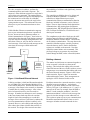
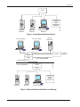
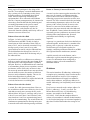
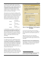
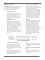
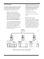
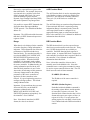
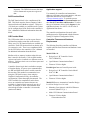
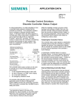
APPLICATION DATA
AD353-113
Rev. 2
April 2012
Procidia Control Solutions
Ethernet Peer-To-Peer Communication
Ethernet is a leading form of network communication
that is often employed on industrial process
networks. Data is exchanged between networkconnected, Ethernet-enabled process controllers,
personal computers, and field instruments to control
and monitor a process. This data can be shared
throughout a company and, by way of the Internet, it
can be made available to remote locations almost
anywhere in the world. Presented here is an overview
of peer-to-peer communication on a private Ethernet
network that includes Procidia™ controllers. See
Application Support on page 9 for a list of
controllers.
There are private and public networks. In this paper,
we are concerned with the private network. A private
network has access intentionally restricted to specific
individuals, usually within a company or within one
specific area within a company. Private networks can
be linked for efficient exchange of data. Open access
characterizes a public network. The Internet is an
example of a public network where anyone with the
requisite computer and software can log on.
In this paper, we discuss what Ethernet is, describe
building a network, and briefly introduce network
addressing. Next, controller configuration and
Ethernet function blocks are discussed. Finally,
controller firmware and hardware requirements are
listed.
The scope of this paper is limited to introductory
material. However, the References section on the last
page has a list of books and manuals that provide indepth information about the above topics plus
network security, wiring, and troubleshooting.
Siemens offers training classes that include
configuring a controller for Ethernet operation; see
the References section. The final word though
belongs to your company’s network administrator.
He or she is a primary source of additional
information about network security, design, IP
addressing, and other critical network issues.
Ethernet and Procidia
Ethernet is simply an agreed upon set of rules that
describes how devices will exchange messages.
These rules are published in IEEE specification 802.3
and they describe in detail the critical aspects of
Ethernet communication including the format of the
data packets and the physical interconnections
(cables and connectors).
The Ethernet form used by Procidia controllers is
Modbus TCP/IP (Transmission Control
Protocol/Internet Protocol). 1 Messages are correctly
addressed and routed by IP; TCP insures that all
packets of data are received correctly. Simply stated,
Modbus TCP/IP is Modbus communication
encapsulated in an Ethernet TCP/IP wrapper.
Before delving further into Ethernet, some Modbus
characteristics need to be mentioned. Modbus is a
common communications protocol supported by
many instrument manufacturers. Modbus
communication is based on one master device and
one or more slave devices, each slave having a
unique identity or address. Usually, the master is a
PC or PLC. Slave devices can be controllers, slave
PLC’s, and field instruments.
Only the master can initiate communication and it
can issue either a data request or a write data
command. The Modbus command contains: the
unique address of the slave to which the message is
directed, the command function code, the starting
register address, and the number of registers affected.
1
Procidia controllers (see page 9) are capable of Modbus
TCP/IP and HTTP over 10BaseT and 100BaseT.
AD353-113
the probability of collisions and significantly increase
network traffic.
The slave recognizes its address, performs the
command operation, and sends a response. The
response is either the data requested or a reply that it
received the write command. The starting register
address and the number of registers affected specifies
the location and size of the data. On a Modbus
network, the master must wait for the reply before
issuing another request. This architecture does not
allow peer-to-peer communication between slave
devices.
The controllers are Modbus slaves, by design, and
respond to Modbus commands. To enable the
controllers to initiate Ethernet peer-to-peer
communication, Ethernet communication function
blocks are included in firmware version 2.40 and
higher. There are three function blocks that initiate
communication: AIE (Analog Input for Ethernet
communication), DIE (Digital Input for Ethernet) and
CIE (Coil Input for Ethernet). Each block issues a
data request command.
Unlike Modbus, Ethernet communication supports
peer-to-peer communication because it permits all
devices, known as hosts in Ethernet parlance, to
initiate communication. In Figure 1, three hosts are
connected together through a hub forming a network.
Any host can send a message through the hub to the
other hosts. However, only one host at a time can
send a message. If two hosts do send messages at the
same time, the messages collide and become
unreadable.
The compliments to the above blocks are the AOE
(Analog Output for Ethernet) and DOE (Digital
Output for Ethernet) function blocks. These blocks
do not initiate communication. They map data to the
controller’s Modbus registers (memory locations)
where the data are stored. Data in the Modbus
registers are available to the network. Note that
controllers cannot initiate write commands. This
privilege belongs to an operator who can initiate
actions through an HMI, such as a Procidia i|station.
Hub
Building a Network
s
2 4 2 3. 4 5
S
100
P
L
S
80
AC K
60
D
PB2
40
A
M
20
UNITS
0
LOOP
0
CLOSE
|
|
||
The manner in which hosts are connected together to
create a network is referred to as the network
topology. This includes the cabling of the networkconnected hosts and the use of hubs, switches, routers
and gateways to accommodate that cabling and create
the desired network structure. Figures 1 and 2 show
simple networks. Figure 3 shows two networks
connected through a router. These arrangements or
topologies will be discussed in this section.
Ethernet
Enabled
Field Device,
Address 2
T C2 0 5 3 . P
PB1
100
OPEN
X03141 S2
Model 353,
Address 3
Control Room HMI,
Address 1
MG00422a
Model 353
Figure 1 Hub-Based Ethernet Network
Each host connected to a network must have a unique
identifier known as an address -- equivalent in
purpose to your home address for Post Office mail
delivery. In Figure 1, the addresses are 1, 2, and 3. A
message can be sent, for example, from the HMI at
address 1 to the controller at address 3; the field
instrument at address 2 will receive the message but
ignore it since the message was not addressed to it.
This is point-to-point or peer-to-peer communication.
Broadcast communication allows a host to send a
message to all other network-connected devices.
Collision avoidance is built into Ethernet through the
use of CSMA/CD (Carrier Sensing Multiple Access
with Collision Detection). When a host needs to send
a message, it first listens to the network, to determine
if another host is sending a message. After a short
period of network inactivity, the host sends its
message. If another host attempts to send a message
at the same instant, both stop and wait a random
length of time before attempting to re-send their
messages. Since each host’s wait time is random, the
previous communication collision is unlikely to be
repeated. However, each collision and ensuing wait
time reduces the volume of traffic that can flow on
the network. The design of the network can reduce
2
AD353-113
Switch
s
s
2 4 2 3. 4 5
2 4 2 3. 4 5
S
100
S
P
L
S
80
AC K
PB1
D
PB2
40
A
M
100
P
L
S
80
AC K
60
60
PB2
20
D
40
A
M
UNITS
20
UNITS
0
0
LOOP
LOOP
|
|
|
100
0
CLOSE
OPEN
|
|
|
100
OPEN
Model 353
Model 353
X03141 S2
MG00422a
0
CLOSE
Ethernet
Enabled
Field Device,
Address 2
T C2 0 5 3 . P
T C2 0 5 3 . P
PB1
X03141 S2
Model 353,
Address 4
Model 353,
Address 1
Control Room HMI,
Address 3
Figure 2 Switch-Based Ethernet Network
PC in Purchasing
PC in Accounting
Internet
Web Server
Gateway
Switch
Router
Note: Router/Switch combination may
be two separate devices.
Office Area Network
Process Area Network
MG00422a
Router
Switch
s
s
2 4 2 3. 4 5
T C2 0 5 3 . P
S
PB1
100
2 4 2 3. 4 5
S
L
80
S
AC K
PB1
D
PB2
UNITS
A
M
P
L
80
S
AC K
20
D
40
40
20
UNITS
0
0
LOOP
LOOP
0
CLOSE
100
60
60
PB2
A
M
Ethernet
Enabled
Field Device
T C2 0 5 3 . P
P
|
|
|
100
0
OPEN
Model 353
X03141 S2
Model 353
CLOSE
|
|
|
100
OPEN
Model 353
X03141 S2
Model 353
Control Room HMI
Figure 3 Ethernet Network with Router and Gateway
3
To/From
Internet
AD353-113
Many people will participate in the design of the
network. Your company’s network administrator will
play a primary role by examining security issues,
assigning addresses, and deciding other critical
issues. Process engineering will identify the
equipment that is to be connected to the Ethernet
network. Company management may be interested in
connecting a network that links the purchasing and
accounting departments to the process control
network. If remote monitoring is required, an
intranet, extranet, or the Internet may also be
connected. Network reliability and security will be of
immense concern to all involved.
Router or Gateway-Connected Networks
A router is used to connect together networks of the
same type, for example, two Ethernet networks.
Figure 3 shows two routers with built-in switches
connecting a process area network to an office area
network. The office network includes the purchasing
and accounting departments, and a web server and
gateway with a security firewall for access to the
Internet. A router can read an address and route a
message to the proper network and to the addressed
host. In addition, a router isolates the networks and
can usually prevent a problem on one network from
affecting other connected networks. Network
performance and reliability are significantly
improved.
Ethernet Network with a Hub
In Figure 1, a hub is used to connect the controller,
field instrument, and HMI. The hub is simply a
central point to which a number of hosts, often as
many as 8-12, can be electrically connected. Every
message sent by a host is sent to every other
connected host but read by only the addressed host.
The hub distributes the message but, since it is a
passive device, it cannot direct the message only to
the addressed host.
A gateway is a general term for devices that link two
networks together, and the router is a member of the
gateway class. A gateway is often able to connect
two different types of networks together, for
example, connecting an Ethernet network to an IBM
SNA (System Network Architecture) network.
A public network, such as the Internet, can be
connected to a private network through a gateway or
a router. For information about configuring a
gateway or router, refer to the manufacturer’s
installation manual.
As pointed out earlier, a collision occurs when two
hosts try to send a message at the same instant. With
only three hosts, network performance is probably
adequate. However, as additional hosts are connected
to accommodate plant or process expansion, network
performance suffers. Since only one host at a time
can access the network and there are now more hosts,
network traffic increases, the number of collisions
increases, and performance degrades. The use of a
hub to interconnect hosts is generally not
recommended. The solution is to replace the hub with
a switch, also known as a switching hub.
IP Address
Ethernet Network with a Switch
This section introduces IP addressing. Addressing is
a complex topic, particularly when several networks
and sub-networks are involved. Your company’s
network administrator will supply host addresses,
masks, subnet addresses, and gateway addresses as
needed. Addressing is an inseparable part of network
design.
A switch, like a hub, interconnects hosts. However,
the switch directs traffic more effectively since it can
read addresses and route a message directly to the
addressed host. In Figure 2, a message sent by host 1
to host 2 is not sent to hosts 3 and 4. Indeed, at the
same time hosts 1 and 2 are communicating, hosts 3
and 4 can be communicating. The switch isolates the
simultaneous communications allowing an increase
in network traffic while reducing message collisions.
Every host on a network needs a unique address. In
Figure 1, addresses 1, 2, and 3 were used. The
Internet Protocol (IP) uses a 32-bit addressing
structure. An example of an IP address is
192.168.0.2. Notice that the complete address is
written as four numbers in a dotted-decimal notation,
i.e. the four decimal groups are connected together by
three dots. Each decimal number has a range of 0 to
255.
4
AD353-113
A portion of the complete address represents the
network address (netid); another portion the subnet
address (subnetid), on a more complex network; and
a third portion the host address (hostid). However, it
is important to remember that all four decimal
numbers provide the complete address. A brief
example of the use of subnet addresses and subnet
masks is provided later in this paper.
If the network is not connected to another network,
particularly the Internet, almost any IP addresses can
be assigned. However, the IANA (Internet Assigned
Numbers Authority) has reserved three blocks of
addresses for private networks. These reserved
address ranges should be used whether or not a
connection to a public network is anticipated.
through
through
through
192.168.0.0
192.168.255.255
or
172.16.0.0
172.31.255.255
or
10.0.0.0
10.255.255.255
Figure 4 Sample Windows TCP/IP Properties
Dialog Box
A default address is provided by a controller. It can
be used in many applications where the process
control network is not connected to other networks.
When a Windows®-based PC is to be configured,
make the needed entries in the dialog box shown in
Figure 4. Your network administrator can provide
addresses, subnet masks, and other necessary
information.
network-connected controller from which data or
status will be obtained. Make a list of each Ethernet
discrete input block created and the loop where it is
located.
Where a discrete value is to be stored in the
controller’s Modbus registers, add a DOE block to
the configuration. Note this register location for later
connection.
Peer-to -Peer Configuration
To configure peer-to-peer communication between
controllers, build each controller’s configuration as
you normally would. Wherever an external analog
value or point is to be exchanged over Ethernet, add
an AIE or AOE function block to the configuration.
Note that more than one AIE block can request data
from a single AOE block. Make a list of each
Ethernet analog block created and the loop where it is
located for later connection.
When finished, return to each configuration and tie
the Ethernet I/O blocks. Next, assign IP addresses to
each controller 2 . The last step is to go through each
AIE and DIE function block and set the source IP
address and Modbus register location.
Where an external discrete value or point is to be
acquired over Ethernet, add a DIE block. Since the
DIE block supports 16 points, it is likely that several
loops will need to connect to it. Create a separate I/O
Discrete loop and place one DIE block for each
2
A default controller address is provided. One controller
on a network can use this address. A unique address will
need to be assigned to each additional controller.
5
AD353-113
Ethernet Function Block
ETH DPLX (Ethernet Duplex mode)
The ETHERNET function block is used to assign the
controller IP address and to set communication
parameters. The ETHERNET function block is
located under Station Function Blocks.
The Ethernet Duplex mode parameter
specifies how devices (e.g. switches, routers)
communicate with each other. It is
recommended to set ETH DPLX parameter
to Automatic mode. When the host registers
with the switch (or gateway), it establishes
the communication mode. The Full-Duplex
and Half-Duplex mode options are available
in the event that other hosts on the network
support only one mode. Consult with the
network administrator before making a
selection other than that recommended here.
IP ADRES (IP Address)
Each controller requires a unique IP address.
Enter the address assigned by the network
administrator. Alternatively, if this is a
private network, use an address from the
blocks of reserved IP addresses listed earlier
in this paper.
ETH Rate
IP MASK (Subnet Mask)
This Ethernet Rate parameter refers to more
than the communication baud rate. It refers
to the network wiring specification and
topology. Most hosts can support both
Ethernet 10BASE-T (10 mbps) and
100BASE-T (100 mbps). Set the ETH
RATE parameter to Automatic. When the
host registers with the switch (or gateway), it
establishes the baud rate for each connection.
The 10BASE-T and 100BASE-T options are
available for unique network topologies.
Consult with the network administrator
before making a selection other than that
recommended here.
The subnet mask is the method used to
identify messages that are addressed to
members of a subnet. More than one subnet
can exist in the same network. If the subnet
address is 192.168.175.0, then use IP mask
255.255.255.0. If the subnet address is
192.168.175.128, then use IP mask
255.255.255.128. Your network
administrator will provide the needed
addresses and masks. Figure 5 is an example
of bit-wise logic illustrates how the subnet
mask works:
•
•
•
•
IP Address
Subnet Mask
AND bit logic
Subnet Address
11000000 10101000 10101111 00000010
11111111 11111111 11111111 00000000
(192.168.175.2)
(255.255.255.0)
11000000 10101000 10101111 00000000
(192.168.175.0)
Figure 5 Subnet Mask Example
IP GATE (Gateway IP Address)
When using a switch, each host-to-switch
connection can be set for either 10BASE-T
or 100BASE-T.
If the local network is isolated by a gateway,
then the gateway IP address needs to be
specified. Typically, it is assigned the first
host address in the subnet, e.g. 192.168.175.1
or 192.168.175.129.
P2P RATE (Peer-to-Peer Communication
Rate)
The Peer-to-Peer parameter specifies in
seconds how often the controller issues a data
request command.
A gateway address must be assigned. If a
gateway is not present, the gateway field
should contain an unused address within the
host subnet (address range).
6
AD353-113
AIE Function Block
The plant master controller will have the
compliment AOE block. The purpose of the
AOE block is to provide a memory location
for the plant FRD value. The plant master
controller, being a Modbus slave, will
respond with the value located in the
specified Modbus registers.
The AIE function block is used to request analog data
from another controller on the network. In a typical
application, a supervisory controller provides an
external set point to a loop controller. Thirty-two
(32) AIE blocks are available per controller.
Example: In a steam powerhouse
application, the plant master controller
regulates the main steam header pressure.
All boilers are connected to the main header
and the header provides steam to the plant.
Each boiler controller relies on the plant
master to dictate the percentage of full
capacity at which it should be running. This
value is the plant fire rate demand (FRD).
IP ADRES (Source IP Address)
The IP address of the source controller is
required.
MB REG (Modbus Register)
To transfer the plant FRD across an Ethernet
network, each boiler controller will contain
an AIE function block in the boiler master
loop. See Figure 6. It replaces the AIN
function block used with traditional field
wiring. The boiler controller will
periodically issue a data request command to
get the latest plant FRD.
MG00422a
Embedded within the Modbus command is
the starting register address and the number
of consecutive registers to be read. The
function block assumes that the data is in
IEEE floating point format and it requests
two registers of data. (A register is 16 bits).
For convenience, the starting register for
each AOE is listed in the User’s Manual
under the AIE function block section.
Switch
s
s
s
2 4 2 3. 4 5
2 4 2 3. 4 5
T C2 0 5 3 . P
T C2 0 5 3 . P
S
PB1
100
S
P
L
S
80
PB1
ACK
S
L
S
AC K
PB1
D
PB2
UNITS
A
M
20
40
A
M
U NITS
0
|
|
|
|
CLOSE
OPEN
|
100
0
OPEN
CLOSE
I/O Discrete
DOE1
DOE2
AIE1
I/O Discrete
I/O Discrete
DOE1
DIE1
Figure 6 Ethernet Peer-To-Peer Communication
7
|
100
OPEN
Boiler Master
AIE1
DIE1
|
Boiler 2
Boiler Master
AOE1
|
X 03141 S2
Boiler 1
Steam Pressure
D
Model 353
X 03141 S2
X 03141 S2
DIE2
|
Model 353
Plant Master
ACK
UNITS
LOOP
0
100
Model 353
S
0
LOOP
CLOSE
L
20
0
LOOP
P
80
40
20
0
100
60
PB2
D
40
DIE1
2 4 2 3. 4 5
T C2 0 5 3 . P
P
80
60
60
PB2
A
M
100
DOE1
AD353-113
Data can be requested from registers other
than AOE blocks. For example, the process,
set point and valve variables can be read
directly from the ODC block. Be sure to
select the Modbus registers from the
Dynamic Loop Floating Point Data (IEEE)
and not the Dynamic Loop Integer Data.
AOE Function Block
It is possible to request IEEE formatted data
from other hosts that support Modbus
TCP/IP protocol. The default host Modbus
address is 1.
The AOE block does not contain scaling information.
If the associated AIE block is requesting scaling
information (Range is Automatic mode), then the
AOE range pointer must be configured to an
appropriate analog input or scalar function block.
Refer to the controller’s User’s Manual for additional
information about this block.
The AOE function block is used to map analog data
to the Modbus registers, to make it available to the
network (i.e. the AIE block in another controller).
Thirty-two (32) AOE blocks are available per
controller.
Important: The AIE function block assumes
that data is in IEEE format and request two
registers of data.
Range
DIE Function Block
When data is to be displayed in the controller
or i|station faceplate, scaling information is
important. This information also affects the
performance of the PID and other loop
function blocks. The standard procedure is
to assign the MINSCALE, MAXSCALE,
DPP and ENGUNITS parameters of an
analog input block. When the RANGE
parameter is in Automatic mode, scaling
information comes from the AOE block in
the source controller. In Manual mode, the
scaling information specified in the AIE
function block parameters is used. In the
Auto mode, the advantage of this parameter
is that any changes made to the scaling
parameters of the source controller are
applied to all other controllers in the
network. It is good engineering practice to
configure all range pointers. The default
setting is Manual mode.
The DIE function block is used to request discrete
data from a second controller on the network. Thirtytwo (32) DIE function blocks are available per
controller. Each DIE function block supports 16
discrete points. A separate DIE block is required for
each controller from which data is requested. Refer to
the controller’s User’s Manual for additional
information about this block.
Note: In Procidia controllers, discrete data is
normally stored in the Modbus coils. Since this
command issues a read register command, it cannot
be used to request controller discrete data. The CIE
block issues the read coil data command.
IP ADRES (IP Address)
The IP address of the source controller is
required.
MB REG (Modbus Register)
Important: If requested data does not come
from an AOE block, set the RANGE
parameter to Manual and set the
MINSCALE, MAXSCALE, DPP, and
ENGUNITS parameters appropriately. See
the controller’s User’s Manual.
Embedded within the Modbus command is
the starting register address and the number
of consecutive registers to be read. The
function block assumes that the data is in bit
format and requests one register of data. (A
register is 16 bits). For convenience, the
starting register for each DOE is listed in the
User’s Manual under the DIE function block
section.
Note: Since data is transferred in IEEE
format, the value is not altered.
8
AD353-113
Application support
Important: The DIE block assumes that data
is in bit format and requests one register of
data.
User manuals for controllers and transmitters,
addresses of Siemens sales representatives, and more
application data sheets can be found at
www.usa.siemens.com/ia. To reach the process
controller page, click Process Instrumentation and
then Process Controllers and Recorders. To select
the type of assistance desired, click Support (in the
right-hand column). See AD353-138 for a list of
Application Data sheets.
DOE Function Block
The DOE function block is the compliment of the
DIE. This block maps the discrete outputs of other
function blocks to the Modbus registers. Thirty-two
(32) blocks are available per controller and 16 points
can be configured per block. Refer to the controller’s
User’s Manual for additional information about this
block.
The controller configurations discussed in this
publication can be implemented with the Siemens
i|config™ Graphical Configuration Utility.
CIE Function Block
Controller Firmware and Hardware
Requirements
The CIE function block is used to request discrete
coil data from another controller on the network.
Thirty-two (32) CIE function blocks are available per
controller. Each CIE function block can obtain up to
16 consecutive coils. There is no compliment block
for the CIE. Refer to the controller’s User’s Manual
for additional information about this block.
The following Procidia controllers are Ethernet
capable when the listed firmware and hardware items
are installed.
Model 353R with:
Modbus coils are memory locations where discrete
data is stored in bit format. Coils are different than
registers and can be visualized as a different sector in
memory. Coils have their own set of data request and
write commands.
Controller discrete logic data is available as outputs
of function blocks. In peer-to-peer communication,
use DIE and DOE blocks where needed to transfer
discrete data. This method is recommended over
using the CIE block because, when using the
Graphical Configuration Utility, the controller
configuration is more thoroughly documented. The
CIE is available for completeness and it allows
access to certain discrete statuses that are not
available via function block outputs. It may be of
value, for example, to know if an alarm has been
acknowledged or that a controller is in run mode
(station coil 00008).
•
Design Level “B” Controller Carrier
TGX:353RRCCB_
•
i|pac Ethernet Communication Board
•
Firmware V2.40 or higher
Procidia i|pac Internet Control System* with:
•
Design Level “B” Controller Carrier Model
iPAC-CC-B4
•
i|pac Ethernet Communication Board
•
Firmware V2.40 or higher
Model 353 Process Automation Controller Design
Level B or Design Level A* with:
9
•
Mounting Case Option 4 with RJ-45 Ethernet
connector (Model 353_4...)
•
Model 353 Ethernet Communication Board
•
Firmware V2.40 or higher
* Discontinued model
AD353-113
References
•
SAMS Teach Yourself Networking in 24 Hours,
Matt Hayden, SAMS Publishing, 2001
•
Networking with Microsoft TCP/IP, Drew
Heywood, New Riders Publishing
•
Networking Complete, Second Edition, Sybex,
Inc., 2001
•
Procidia i|pac User’s Manual, UMiPAC-1, Rev.
4 or higher
•
Model 353 Process Automation Controller
User’s Manual, UM353-1, Rev. 9 or higher
•
Siemens Controller Configuration Training Class
For information, follow the navigation on the
previous page and click Training or request
information from:
Siemens Industry, Inc.
Technical Training Center, MS510
1201 Sumneytown Pike
P.O. Box 900
Spring House, PA 19477-0900
Procidia, i|pac, i|ware, i|config, and 352Plus are trademarks of Siemens Industry, Inc. Other trademarks are the property of their respective owners. All
product designations may be trademarks or product names of Siemens Industry, Inc. or other supplier companies whose use by third
parties for their own purposes could violate the rights of the owners.
Control circuits are provided only to assist customers in developing individual applications. Before implementing any control circuit, it
should be thoroughly tested under all process conditions.
Siemens Industry, Inc. is not responsible for changes to product functionality after the publication of this document. Customers are
urged to consult with a Siemens Industry, Inc. sales representative to confirm the applicability of the information in this document to the
product they purchased.
Siemens Industry, Inc. assumes no liability for errors or omissions in this document or for the application and use of information in this
document. The information herein is subject to change without notice.
Copyright © 2012, Siemens Industry, Inc.
10