1
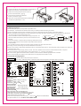
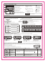
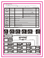
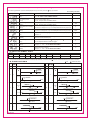
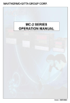
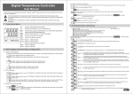
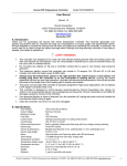
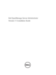
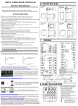
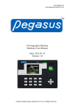
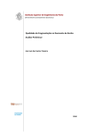
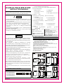
(1) Control action
Digital PID Controller
AI-400,AI-700,AI-800,AI-900
INSTRUCTION MANUAL
F: PID reverse action with autotuning
(2) Input type,(3) Range code: See"8.INPUT RANGE TABLE"
(4) Control output [OUT]:
M:Relay contact
MIC3AI-E1
Carefully read all the instructions in this manual. Please place
this manual in a convenient location for easy reference.
8: Current(DC4 ~ 20 mA)
5: DC0-5VDC
6: DC0-10VDC
T: Zero trigger (for triacs driving)
(5) Remark:
N: No
WARNING
N: No alarm
J: Process low alarm
N: No alarm
A: Deviation high alarm
H: Process high alarm
B: Low deviation alarm
J: Process low alarm
(8) Power
A: 220VAC
B 85-265VAC
Specification:
Model of the controller:AI-900
Code: FKA4-MN*AN-B
Size: 96mm x 96mm
Control action: PID reverse action
Input: K type thermocouple
Check MODEL and CODE
Out put: Relay output
is very important when ordering.
Alarm: 1 deviation high alarm (AL1)
Power: 85~265VAC
2. MOUNTING
2.1 Mounting Cautions
(1) Use this Instrument within the following ambient
temperature and ambient humidity.
Allowable ambient temperature: 0 to 50 C
Allowable ambient humidity: 45 to 85% RH
(2) Avoid the following when selecting the mounting location.
Rapid changes in ambient temperature which may cause condensation.
Corrosive or inflammable gases.
Direct vibration or shock to the mainframe.
Water,oil,chemicals,vapor or steam splashes.
Excessive induction noise, static electricity, magnetic fields or noise.
Direct air flow from an air conditioner.
Exposure to direct sunlight.
Excessive heat accumulation.
2.2 Dimensions
Unit:mm
44.0
AI-800
AI-400
Unit:mm
50
14.6
1
90.0
104.0
14.6
96
50
1
13.6
80
1
1
13.6
80
AI-900
Unit:mm
Unit:mm
UP
UP
90
AI-700
(4) (5)
(6) (7)
90.0
96
67.5
80.0
104.0
14.6
96
74
-
-
14.6
(8)
1
13.6
MIC3AI-E1
E 24VAC
Model: AI-900
74
(3)
D 24VDC
Example
1. PRODUCT CHECK
(1) (2)
See"5.5 Initial Setting "
(7) Alarm 2[AL2 for low alarm]
44.0
This instrument is protected from electric shock by reinforced
insulation. Provide reinforced insulation between the wire for
the input signal and the wires for instrument power supply, source
of power and loads.
This instrument is design for installation in an enclosed
instrumentation panel. All high-voltage connections such as
power supply terminals must be enclosed in the instrumentati on
panel to avoid electric shock by operating personnel.
All precautions described in this manual should be taken to avoid
damage to the instrument or equipment.
All wiring must be in accordance with local codes and regulations.
Always
observe precautions
described in this manual.
Otherwise serious injury or accident may result.
Do not allow metal fragments or lead wire scraps to fall inside this
instrument. This may cause electric shock, fire or malfunction.
Firmly tighten each terminal screw at the specified torque.
Otherwise electric shock or fire may result.
Do not place any obstacle around this instrument in order
not to impede radiation of heat. And do not close ventilation holes.
Do not connect wires to unused terminals.
Before cleaning the instrument, always turn off the power supply.
Remove stains from this instrument using a soft, dry cloth. Do not
use a volatile solvent such as thinner in order to avoid deformation
or discoloration.
Do not rub nor strike the display unit of this instrument with a hard
object.
H: Process high alarm
44.0
58.0
CAUTION
A: Deviation high alarm
B: Low deviation alarm
67.5
An external protection device must be installed if failure of this
instrument could result in damage to the instrument, equipment
or injury to personnel
.
All wiring must be completed before power in turned on to prevent
electric shock, fire or damage to instrument and equipment .
This instrument must be used in accordance with the
specifications to prevent fire or damage to instrument and
equipment.
This instrument is not intended for use in locations subject to
flammable or explosive gases.
Do not touch high-voltage connections such as power supply
terminals , etc. to avoid electric shock.
AI-400 (Size:48x48mm)
AI-800 (Size:48x96mm)
AI-700 (Size:72x72mm)
AI-900 (Size:96x96mm)
See"5.5 Initial Setting "
(6) Alarm 1[AL1 for high alarm]
50
!
V: Voltage pulse
1
80
1
13.6
1
80
1
2.3 Mouting Procedures
Mounting bracket
(1) Prepare the panel cutout as specified in 2.2 Dimensions.
(2) Insert the instrument through the panel cutout.
(3) insert the mounting bracket into the mounting
groove of the instrument.
Fig.1
(4) Pull till chick sounds to the direction
shown by the arrow.(Fig.2)
(5) The other mounting bracket should be installed
U
P
U
P
the same way described in 3. to 4.
Fig.1
Fig.2
3. WIRING
3.1 Wiring cautions
(1) For thermocouple input, use the specified compensation wire.
(2) For RTD input , use leads with low resistance and having no resistance differences among the 3 leads.
(3) Conduct input signal wiring away from instrument power, electric equipment power and load lines to avoid noise induction.
(4) Conduct instrument power wiring so as not to be influenced by noise from the electric equipment power. If the instrument may be affected
by external noise, a noise filter should be used.
Twist these leadwires
* Shorten the distance between twisted power supply wire pitches. The
instrument power
IN
shorter the distance between the pitches, the more effective for noise
OUT
Noise filter
reduction.
Minimize
distance
Shorten distance between
pitches
* Install the noise filter on the panel which is always grounded and minimize
Instrument
power
terminals
the wiring distance between the noise filter output side and the instrument
power terminals.
* Do not install fuses and/or switches on the filter output signal since this may lessen filter effect.
(5) For wiring, use wires conforming to the domestic standard of each country.
(6) Abot 4 to 5 seconds are required as the preparation time for contact output after power on. Use a delay relay when the output line is used for an
external interlock circuit.
(7) This instrument has no power supply switch nor fuses. Therefore, install the fuse close to the instrument and the switch, if required.
*Recommended fuse rating: Rated voltage; 250V Rated current; 1A * Fuse type; Time-lag fuse
(8) Do not excessively tighten the terminal screws. In addition, use the solderless terminal appropriate to the screw size.
(9) To the instrument with power supply of 24V, please be sure to supply the power from SELV circuit.
3.2 Terminal Configuration
CAUTION
(1)All the under hookups are only for reference.
(2)For wiring, please according to the hookup label which was glued on the plastic case of controller.
AI-700
AI-400
1
L
11
2
NO
AC85~265V
NO
OUT Voltage
NO
5
mA,VDC
AL2
AL1
3
4
6
N
mA
For SSR Current
12
13
14
RTD
A
7
9
TC
10
L
8
AL2
AC85~265V
2
3
NO
9
2
10
AL2
12
N
NO
OUT
AL1
11
L
AC85~265V
N
Voltage mA,V
For SSR Current
3
NC
13
NO
NO
mA,VDC
4
5 OUT
Power supply voltage:
AC85~265V
NO
(Frequency 50/60Hz Rating 85~265V Ac)
6
22 to 26 V AC
NC
(Frequency 50/60Hz Rating 24V AC)
22 to 26V DC Rating 24V Dc
7
Power consumption
5VA max (at 24V AC)
160mA max (at 24V DC)
7VA max(at 100V AC)
10VA max (at 240V AC)
Alarm outut rated:
Relay contact output 250V AC, 3A (Resistive load)
Control output rated
Relay contact output: 250V AC,3A(Resistive load)
Voltage pulse output: 0/12 V DC (Load resistance 600 or more)
Current output: 4 to 20mA DC (Load resistance 500 or less)
Trigger output(for triac driving):100A or less
AI-900
1
NC
8
B
B
1
AI-800
RTD
A
Voltage mA,V
For SSR Current
11
4
12
5
14
AL1
15
NO
B
13
16
6
TC
B
14
7
mA,VDC
17
8
RTD
18
A
B
9
19
TC
10
B
20
must be connected between
the input terminals. See 5.6 **A "INPUT TYPE SYMBOL TABLE"
**For the current input (0-20mA or 4-20mA) specification, a resistor of 500
2
MIC3AI-E1
4. PARTS DESCRIPTION
1. Measured value (PV) display [Green]
* Displays PV or various
1
parameter symbols
parameter set values
3. Indication lamps
*Control output lamps (OUT,OFF)
[Green] OUT:Light when output is turned on.
[Red]OFF:Light when output is turned off.
5
7
6
calling up and set
registration
*Alarm output lamps (AL1,AL2)
* Displays SV or various
3
4
(Set key)
Used for parameter
value
2. Set value(PV)display [Red]
2
4.
*Autotuning (AT) [Green]
Flashes when autotuning is
activated.
[Red]
5.
AL1: Lights when alarm 1 output
6.
(Down key)
Decrease numbers
is turned on.
Shift &Assistant key
7.
(Up key)
Decrease numbers
Al2: Lights when alarm 2 output
is turned on.
CAUTION
To avoid damage to instrument, never use a sharp
object to press keys.
5. SETTING
5.1 Calling up procedure of each mode
*1. Input type and input range display
This instrument immediately confirms input type and range following power on.
Example: For a controlleer with the K thermocouple input type and range from 0 to 1300 C .
1. Input type display
PV
:Indicates input type (See table **A)
Power on
Power on
Input type display
Input range display
(Display for
approx.5 sec)
*1
SV
The instrument returns to the PV/SV
display mode status if key operation
is not performed for more than 1 minute.
PV/SV display mode
(Normal display)
Press
: Input range high
Display changes automatically
key
SV setting mode
Press the
key
less than 0.5 s
**A: Input type table(see "14.0 Input range table")
Press the
key
Display
Thermocouple
Input
Press the
key
J
K
S
E
T
B
R
User level(Level1)
Press the
key
for 3 sec .
Press the
key
for 3 seconds
Display
PID level (Level 2)
Press the
key while
pressing the
key
for 3 seconds.
Initialization Mode
Input level (Level 3)
Standard analog signal(Voltage and current)
Resistance thermometer
Input
Press the
key
for 3 sec .
Pt100
DC0-10V,DC 0-20mA
DC2-10V,DC 4-20mA
5.2 Setting set value(SV) Example: Following is an example of set value(SV) to 200 C
(1)Set to the SV setting mode
(2)Shift of the digit brightly lit
(4) Set value entry
(3) Numeric value change
PV
PV
PV
PV
SV
SV
SV
SV
In the normal display mode
Press
key to enter the
SV setting mode.
The digit which flashing
is settable.
Press the shift key
to
shift the digit which lights
brightly up to the hundreds
dights
Caution
Press the UP key
to set "2".
Pressing the UP key increase
numerals, and pressing the
DOWN key
decrease
numerals.
After finishing the setting, Press
the
key, All of the set value
digits stop flash and as a result
the instrument return to
PV/SV display mode.
*Even if the displayed value is changed, it is not registered. To register it , press the SET key.
5.3 Setting parameters other than set value (SV)
The setting procedures are the same as those of example (2) to (4) in the above "Setting set value (SV)". Press the SET key after the
setting end shifts to the next parameter. When no parameter setting is required, return the instrument to the PV/SV display mode.
5.4 User level (Level1)
5.4.1User level parameter setting mode.
Press the "SET "key once less than0.5 s to go to user level.
The following parameter symbols are displayed one by one every time the
Symbol
Name
Alarm1
AL1
Alarm2
AL2
Auto tuning
At)
MIC3AI-E1
Setting range
Deviation orProcess alarm,
-1999 to 9999
0:AT end or cancel
1:AT start or execution
key is pressed.
#1: Factory set value
Description
Set the alarm value for alarm1 or alarm2.
Alarm differential gap=HYS,when P 0
Use AT function to automatically calculate and set the
optimize PID value for your system.
Turns the autotuning ON/OFF
#1
10 or10.0
0
3
5.5 PID level (Level2)
Press the
key for 3 seconds to PID level
After the value be registered ,you can press
key for 3 seconds to return the instrument to the PV/SV display mode.
The following parameter symbols are displayed one by one every time the
key is pressed.
#1: Factory set value
Symbol
Setting range
Name
Description
#1
20.0
Proportional
band (P)
0.0~999.9
ON/OFF control if set to 0 (0.0)
ON/OFF action differential gap=HYS
Differential gap
for alarm or output
(HYS)
0 to 9999
Out differential gap=HYS,when P=0 (ON/OFF action)
Alarm differential gap=HYS,when P 0(PID action)
Integral time (I)
0~3600 seconds
Set the time of integral action to eliminate
the offset occurring in proportional control.
150
Set the time of derivative action to improve
control stability by preparing for output changes.
30.0
Derivative time (d) 0.0~999.9 seconds
Proportioning
cycle (CYCt)
1.0~200.0 seconds
Output manipulated
variablelowest limit
(OPL)
Output manipulated variable lowest limit .
Range : 0 to 100%
Relay contact output :20S
Voltage pulse (for SSR) :2S
0
20.0
or 2.0
0
Output manipulated Output manipulated variable highest limit .
variable highest limit Range : 0 to 100%
(OPH)
100
Proportional reset Overshooting restricted by the proportional effect.
(Ar)
10 or 10.0
Overshooting turn
off (OFF)
Output forced turning off when the PV value overshooting .
Setting range: 0 to 100
Set data lock
(LCK)
0: All parameters can be changed
1: Only SV can be changed
2: No parameters can be changed
3
Performs set data change enable/disable.
0
5.6 INPUT Level (Level 3)(Initial Setting )
Password mode
Press the
SET key
Press the
key while
pressing the
key for 3 s.
Password mode
Input level
Press the
SET key
Press the
SET key
Press the
SET key
Setting the
password to 0808
PV/SV display mode
(Normal display)
Press the
key while
pressing the
key
for 3 s.(Fig.3)
(Fig.3)
Press the
key .
INPUT LEVEL
PASS WORD
MODE
Press the
key.
Setting the
password to 0808.
Highest value
of PV display
(ANH1)
INPUT LEVEL
PASS WORD
MODE
Press the
key.
Low setting
limiter
(LSPL)
4
key.
key.
Press the
High setting
limiter
(HSPL)
Press the
key.
PV bias
(OFST)
Lowest value
of PV display
(ANL1)
Input type
select
(InPt)
Press the
Press the
Decimal point
(dP)
key.
Press the
PV follow-up
(FILT)
The instrument returns to the PV/SV
display mode status if key operation
is not performed for more than 1 minute.
Normal display
Alarm2 type
selection
(ALd2)
key.
Press the
SET
key.
Alarm1 type
selection
(ALd1)
MIC3AI-E1
After the value be registered ,when no parameter setting is required, Press the
The following parameter symbols are displayed one by one every time the
key for 3 s to return the instrument to the normal display.
key is pressed.
#1: Factory set value
Symbol
Name
Description
#1
Main input type select
(InPt)
Input type selection as:thermocouple(TC),RTD,etc.
See **A "INPUT TYPE SYMBOL TABLE"
K
Low setting limiter
(LSPL)
Set lower point within input
see 14. chapter "INPUT RANGE TABLE"
0
High setting limiter
(HSPL)
Set higher point within input
see 14. chapter "INPUT RANGE TABLE"
Lowest value of PV display
(ANL1)
Lowest value display when analog signal inputs,Such as 4-20mA input.
The value of PV display when input 4 mA. Only for s tandard analog signal input.
0
Highest value of PV display
(ANH1)
Highest value display when analog signal inputs,Such as 4-20mA input.
The value of PV display when input 20 mA. Only for s tandard analog signal input.
5000
Decimal point
(dP)
Only for standard analog signal input (current or voltage inputs) .
Range:0~3
400
0
Sensor correction is made by adding bias
value to measured value(PV).
PV bias
(OFSt)
PV follow-up
(FILt)
0
PV variable-value control,
Setting range: 0 to 10
PV will response slower if SOFT is bigger.
2
Alarm1 type selection
(ALd1)
Select the type of alarm1
range:0~4 See **B "ALARM TYPE TABLE"
2
Alarm2 type selection
(Ald2)
Select the type of alarm2
range:0~4 See **B "ALARM TYPE TABLE"
0
**A: INPUT TYPE SYMBOL TABLE
InPt Setting
Input type
Range
E
J
K
S
T
DC0-10V ,(**DC 0-20mA) DC2-10V ,(**DC 4-20mA)
Pt100
R
B
-50 to1350 C -50 to1000 C -50 to1000 C -50 to 1750 C -20 to400 C 50 to1800 C -20 to1750 C
1,All input change in the above groups is possible by keyboard.
2**,For the current input (0-20mA or 4-20mA) specification, a resistor of 500
-199.9 to600.0 C
-1999 to9999
must be connected between the input terminals.
**B: ALARM TYPE TABLE
N
:SV
Alarm1 mode specification
CODE
N
No Alarm
0
Deviation high alarm
AL1
0
A
Deviation high alarm
AL2
HYS Alarm ON
LOW
0
HIGH
SV+AL1
SV
HYS Alarm ON
LOW
A
2
HYS
LOW
2
Deviation high alarm
AL2<0
Alarm ON
HYS
HIGH
SV
SV+AL1
LOW
Alarm ON
LOW
B
4
SV-AL1
SV
AL2
HIGH
LOW
B
AL1<0
LOW
4
SV-AL1
1
HYS
Alarm ON
AL2<0
HIGH
LOW
H
1
J
3
LOW
HIGH
NOTE: Alarm differential gap=HYS,whenP
MIC3AI-E1
SV-AL2
HIGH
Alarm ON
AL2
AL2Value
LOW
HIGH
Process low alarm
Alarm ON
HYS
AL1
AL1Value
HYS
SV
HYS
Process low alarm
Alarm ON
HIGH
Process high alarm
Alarm ON
AL1
AL1Value
LOW
SV
Low deviation alarm
Process high alarm
H
SV-AL2
HYS
SV
HYS
0
Low deviation alarm
Alarm ON
HIGH
SV
SV+AL2
Alarm ON
HYS
0
Alarm ON
Low deviation alarm
Low deviation alarm
AL1
HIGH
SV+AL2
SV
Deviation high alarm
AL1<0
:Alarm set value
Alarm2 mode specification
CODE
No Alarm
0
-1999 to9999
J
HIGH
3
LOW
HYS
AL2
AL2Value
HIGH
0(PID action)
5
6
1)
2)
3)
4)
5)
PID AUTOTUNING (AT) FUNCTION
Autotuning (AT) start
Press the
key for USER level.
Looking for the parameter "AT ".
Set "AT" value from 0 to 1.
Press the
key start auto tuning.
Press the
key to return to the instrument to
the PV/SV display mode.
(If AT be started ,the AT lamp will be lighted on and the lamp is
flashing)
PV
values manually. It is possible to happen when the set value
is around the ambient temperature or is close to the maximum
temperature achieved by the load.
Requirements for AT start
Start the autotuning when all following conditions are satisfied:
(1) Prior to starting the AT function, end all the parameter settings
other than PID.
(2) Confirm the LCK function has not been engaged.
PV
When the autotuning is finished, the controller will
automatically return to PID control.
SV
100%
Output %
0%
Requirements for AT cancellation
ON
OFF
ON
OFF
The autotuning is canceled if any of the following conditions exist.
(1) When the parameter "AT " value is changed.
(2) When the power is turned off.
(3) When power failure longer than 20ms occurs.
Time
ON/OFF control
(Autotuning)
PID control
(After autotuning
Autotuning (AT) automatically measures, calculates and sets the
optimum PID. The following conditions are necessary to carry out
autotuning and the conditions which will cause the autotuning to
stop.
If the AT is canceled, the controller immediately changes to
PID control. The PID values will be the same as before AT
was activated.
When AT is completed, the controller immediately changes to
PID control. If the control system does not allow the AT cycling
process, set each PID constant manually to meet the needs of
the application.
Caution for using the Autotuning (AT)
When a temperature change(UP and/or Down) is 1 or less
per minute during Autotuning, Autotuning may be cancelled
before calculating PID values. In that case, adjust the PID
7.ERROR DISPLAYS
Error display
Turn off the power once. If an error occurs
after the power is turned on again, please
contact sales office or the agent.
RAM failure(Incorrect set date write or check sensor and
sensor connection,etc.)
[Flashing]
Overscale and Underscale
Measured value(PV)
[Flashing]
PV is outside of input range
!
Overscale:
WARNING
To prevent electric shock, always turn
off the power before replacing the
sensor.
PV is above the high input display range limit.
[Flashing]
Underscale:
PV is below the low input display range limit.
Check input type, input range, sensor
and sensor connection..
[Flashing]
8. INPUT RANGE TABLE
Input type
0
0
0
0
0
0
0
0
K
to
to
to
to
to
to
to
to
Code
100
200
400
600
800
1000
1300
1350
K
K
K
K
K
K
K
K
A1
A2
A4
A6
A8
A0
B3
B4
B
Input type
T
Input type
0
0
0
0
0
0
0
J
to
to
to
to
to
to
to
Code
100
200
300
400
600
800
1000
Input type
S
*1
*1
*1
0
0
0
to
to
to
A1
A2
A3
A4
A6
A8
A0
J
J
J
J
J
J
J
Code
1000
1600
1750
S
S
S
A0
B6
B8
Input type
to 1300
*1 50
to 1800
*1 50
0
0
0
0
to
to
to
to
E
to
to
to
to
to
to
to
to
B3
B8
Code
100
200
300
400
T
T
T
T
100
200
300
400
500
600
800
1000
E
E
E
E
E
E
E
E
Input type
0
0
0
0
0
0
0
0
Code
B
B
A1
A2
A3
A4
R
Input type
600
0
to
*1
*1
to 1000
0
*1
to 1300
0
to 1750
0
*1
Input type
0 to 10VDC
2 to 10VDC
4 to 20mA *2
0 to 20mA *2
-1999 to 9999
Input type
Code
R
R
R
R
A6
A0
B3
B8
Code
V
V
A
A
04
09
03
02
Pt100
0.0
0.0
0.0
0.0
0.0
0.0
-199.9
-199.9
-199.9
-100.0
-100.0
-50.0
-50.0
-50.0
Code
to 100.0
to 200.0
to 300.0
to 400.0
to 500.0
to 600.0
to +100.0
to +200.0
to +600.0
to +100.0
to +200.0
to +50.0
to +100.0
to +200.0
D
D
D
D
D
D
D
D
D
D
D
D
D
D
D1
D2
D3
D4
D5
D6
E1
E2
E6
F1
F2
G0
G1
G2
Code
A1
A2
A3
A4
A5
A6
A8
A0
(*1) 0 to 400 C: Accuracy is not guaranteed.
(*2)For the current input (0-20mA or 4-20mA) specification, a resistor of 500
must be connected between the input terminals.
JULY.2010.(P)
6
MIC3AI-E1