1
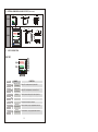
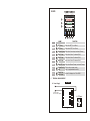
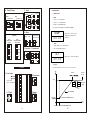
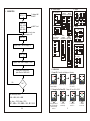
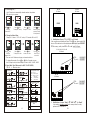
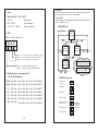
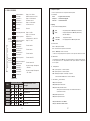
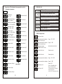
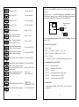
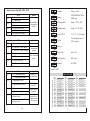
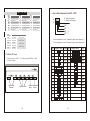
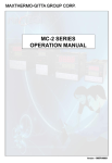
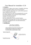
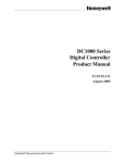
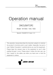
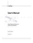
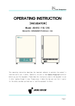
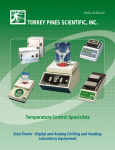
USER’S MANUAL
Manual for
PID CONTROLLER
PV
OUT1
PV
OUT2
SV
AT
AL 1
SV
AL 2
PRO
OUT1 OUT2 AT
AL 1 AL 2 AL 3 MAN PRO
%
OUT1
0
20
40
60
80
100
SET A/M
SET
EQ-TB100
EQ-100
EQ-900
EQ-900
NQA
QSR
JAS-ANZ
Registration No.
S I 9 1 0 7 9 9 I N
HALLMARK OF EXCELLENCE
ISO 9001-2000
C E RT I F I E D
HTA INSTRUMENTATION PVT LTD.
73, Ramachandra Agrahara, Near T. R. Mills, Chamarajpet, Bangalore-18.
TEL: 080-26749750, 26759253 FAX: 080-26740681,
E-mail: [email protected], Web: www.htaipl.com
- EXTERNAL DIMENSION & PANEL CUTOUT [Unit : mm]
50
14
+0.5
44.5 0
OUT1
PV
EQ-100
+0.5
44.5 0
60
OUT2
AT
AL 1
SV
AL 2
70
50
PRO
SET
EQ-TB100
65
96
14
80
+0.5
90.5 0
PV
+0.5
90.5 0
SV
EQ-900
OUT1 OUT2 AT
116
96
AL 1 AL 2 AL 3 MAN PRO
%
OUT1
0
20
40
60
80
100
SET A/M
111
EQ-900
-
PARTS DESCRIPTION
EQ-100
8
OUT1
PV
9
OUT2
1
AT
AL 1
SV
AL 2
2
PRO
SET
10
11
12
15
EQ-100
3
SYMBOL
5
6
7
NAME
PV
1
Measured value
(PV) display
SV
2
Setting value
(SV) display
SET
3
Set Key
A/M
4
5
FUNCTION
Display PV or various parameter Symbols (Red)
Display SV or various parameter set values (Green)
Used for parameter calling up & set value registration
Auto/Manual Key Switches between Auto (PID) output mode & Manual Output
Shift Key
Shift digits when settings are changed
6
Down Key
Decrease numbers (*Only for programmable controller)
(*Program Hold)
7
Up Key
(*Program Run)
Increase Numbers (*Only for programmable controller)
2
EQ-900
8
9
10 11 12 13 14 15
PV
1
SV
2
OUT1 OUT2 AT
16
AL 1 AL 2 AL 3 MAN PRO
%
OUT1
0
20
40
60
80
100
SET A/M
EQ-900
3
SYMBOL
4
5
6
7
NAME
FUNCTION
OUT1 Lamp
Light when OUT1 is on (Green)
OUT2 Lamp
Lights when OUT2 is on (Green)
OUT1
8
OUT2
9
AT
10
Auto-tuning Lamp Lights when Auto-tuning is activated (Orange)
AL1
11
Alarm-1 Lamp
Lights when Alarm 1 is activated (Red)
AL2
12
Alarm-2 Lamp
Lights when Alarm 2 is activated (Red)
AL3
13
Alarm-3 Lamp
Lights when Alarm 3 is activated (Red)
MAN
14
Manual O/P Lamp Lights when Manual Output is activated (Orange)
PRO
15
Program Running Flashes when program running
Lamp
(Only for programmable controller)
OUT%
16
Output% BarGraph Display
Output% is displayed on 10-dot LEDS
- TERMINAL ARRANGEMENT
EQ-100
A. Power Supply
1
AC 85~265V
DC 15~50V (Option)
6
11
2
12
3
13
4
14
5
3
7
8
9
10
H. CT Input
11
CT
12
C. Input
B. Control Output
OUT1
+ +
2
+ +
5
–
3
–
–
–
B
– 10
•
8
8
I.
SET2.1=1 g To display AL3
9
+9
II.
SET4.1=1 g To display ALD3
10
– 10
A
III. ALD3=9 g Open RAMP option
IV. Then, AL3 will not display. It was replaced by RAMP.
RAMP
D. Alarm
(Option)
OUT1
(1Ø Zero Cross
Control)
OUT1
(Proportional Motor
Valve Control)
11 G1
(Use OUT1 & OUT2)
(Motor Valve Control)
AL1
AL2
2
13
11
3
14
12
12 CLOSE
13 G2
13 OPEN
14 K2
14 COM
E. Transmission F. Communication
TRS
+
RS232
•
SOAK :
I.
ALD1 / ALD2=19 g To use Sock Timer.
II. AL1 / AL2 will display as below:
TTL
RS485
11
RD
11 Dx– 11 RD
– 12
SD
12
SG
13
Dx+
00.00
Range : 00.00 ~ 99.99(°C/ min)
(If RAMP is not used please set
ALD3 to 0)
AL1
11
12 K1
RAMP & SOAK
7
• RAMP :
8
9
APPLICATIONS
7
B
Relay SSR mA / V
4
TC / mV
RTD
mA / V
+ 7
OUT2
Relay SSR mA / V
-
11
12 SD
12
SG
13
AL1
Range : 00.00 ~ 99.59 (Hour. Minute)
00.00
• Example :
EQ-900
SV=100°C RAMP=10.00 (/min) ; AL1=00.10 min ; PV=25°C
°C
Time on
A. Power Supply
AC 85~265V
DC 15~50V (Option)
H. CT Input
14
CT
15
E. Transmission
1
21
31
11
2
22
32
12
3
23
33
13
4
24
34
14
5
25
35
15
6
26
36
16
7
27
37
17
F. Remote
Remote SV
+
8
28
38
18
9
29
39
19
10
30
40
20
Time up
AL1 on
if PV > = SV(100°C)
TRS
+
39
100°C
– 40
AL1
00.10
00.01
00.10
Sock Timer
counts
1sec.
SV=SV+RAMP
14
PV=25°C
SV=PV (When start RAMP function)
– 15
t
Power on
4
5 seconds (Start RAMP function)
21
B. Control Output
- CALIBRATION
SET 2.2 = 1
OUT1
To display ANL1
& ANH1
Relay SSR mA / V
NO
8
NC
+ +
–
10 COM
at INPUT Level
OUT2
Return User Level to view
the changing of PV
–
Relay SSR mA / V
6
+ +
7
–
mA / V
+ 17
18
33 G2
33 RG2
19
39
35 TG1
– 20
40
PROT
RTD
TC / mV
17
17
18
18
19
+19
20
– 20
B
31 RG1
31 G1
9
ANL1=0
ANH1=5000
LSPL=0
USPL=5000
C. Input
OUT1
OUT1
(1Ø Zero
(3Ø Zero
Cross Control) Cross Control)
B
D. Alarm
37 TG2
39
AL1
–
AL2
AL3
3
NC
NC
11 6
4
NO
NO
12 7
5
COM
COM
40
OUT1
(Proportional Motor
Valve Control)
Inputs 4mA
OUT1
(1Ø Phase
Angle Control)
6
7
CLOSE
PROT
OUT1
(3Ø Phase
Angle Control)
31
G1
31
G1
32
K1
32
K1
RS232
Adjusts "ANL1" until PV Display = 0
8
OPEN
9
Inputs 20mA
10
33
G2
33
G2
34
K2
34
K2
35
G3
36
K3
35
COM
36
PROT
13
G. Communication
RS485
TTL
RD
14
Dx–
14 RD 14
SD
15
Dx+
15
SG
SG 16
16
(Remote SV)
RS232
SD
15
RS485
RD
31
Dx
31
SD
32
Dx+
32
SG
33
39
Adjusts "ANH1" until PV Display = 5000
Inputs 4mA to CHECK LOW
Inputs 20mA to CHECK HIGH
40
- OPERATIONS
1. Power ON : Controller will display as following
PV
PV
PV
SV
SV
SV
OUT1
OUT2
AT
AL 1
AL 2
AL 3
MAN
PRO
%%
OUT1
0
20
40
60
80
OK ?
YES
Set the range you want :
20
AT
AL 1
AL 2
AL 3
MAN
PRO
OUT1
%%
0
20
40
60
80
PV
SV
OUT2
AT
AL 1
AL 2
AL 3
MAN
PRO
OUT1
%%
OUT1
100
0
20
40
60
80
AT
AL 1
AL 2
AL 3
20
40
60
80
MAN
PRO
%%
100
0
SET A/M
Display input type
OUT2
OUT1
100
SET A/M
Display Range
(0.0~400.0)
Read for use
2. Change the Set Value (SV) : Change SV from 0.0 to 100.0
PV
PV
PV
SV
SV
SV
OUT2
AT
AL 1
AL 2
AL 3
20
40
60
80
MAN
PRO
%%
OUT1
Ex : Low = -20.0 ; High = 50.0
SET : LSPL = -20.0 ; USPL = 50.0 ; DP : 000.0
OUT2
OUT1
SET A/M
Light all LEDs & all
7 segment displays
OUT1
LOW = LSPL ; HIGH = USPL
OUT1
100
SET A/M
NO
PROT
0
100
SET A/M
Press
Key
The SV number started to
flash. The flashing digit
indicates which digit
can be set.
OUT1
OUT2
AT
AL 1
AL 2
AL 3
20
40
60
80
MAN
PRO
OUT1
%%
OUT1
0
PV
SV
OUT2
AT
AL 1
AL 2
AL 3
20
40
60
80
0
SET A/M
MAN
PRO
%%
OUT1
100
100
SET A/M
Press
Key
To select the
hundreds digit.
Press
Key
To change the
number to 1.
5
OUT1
OUT2
AT
AL 1
AL 2
AL 3
20
40
60
80
MAN
PRO
%%
OUT1
0
100
SET A/M
Press SET Key
To store the
new set value.
3. Auto-tuning (AT) :
Use AT function to automatically calculate and set the optimize
PID value for your system.
PV
PV
PV
SV
SV
SV
OUT1
OUT2
AT
AL 1
AL 2
AL 3
20
40
60
80
MAN
PRO
OUT1
%%
OUT1
0
OUT2
AT
AL 1
AL 2
AL 3
20
40
60
80
MAN
0
SET A/M
PRO
OUT1
%%
OUT1
100
Press SET Key
To display
Parameter AT.
AT
AL 1
AL 2
AL 3
20
40
60
80
MAN
PRO
OUT1
%%
OUT2
AT
AL 1
AL 2
AL 3
20
40
60
80
MAN
0
100
SET A/M
Press SET Key
Start Auto-tuning
process (AT lamp
will be lighted on)
Press
Key
Change AT to "YES"
Change AL 1 value to "5.0" (AL 1 active, if PV exceeds SV over 5.0)
PV
SV
OUT1
PV
SV
OUT2
AT
AL 1
AL 2
AL 3
20
40
60
80
MAN
PRO
OUT1
%%
OUT1
0
AT
AL 1
AL 2
AL 3
20
40
60
80
SET A/M
MAN
PRO
OUT1
%%
0
SV
OUT2
AT
AL 1
AL 2
AL 3
20
40
60
80
MAN
PRO
OUT1
%%
OUT1
100
0
SET A/M
Press SET Key
To display
Parameter AL1.
R1
R2
R5
R3
AT
AL 1
AL 2
AL 3
20
40
60
80
MAN
PRO
%%
0
SET A/M
Press
Key
To change AL1 value
OUT2
OUT1
100
100
SET A/M
9 .....
6
6 ... 9
10
Modification of Input “TC”
“RTD” (on PC board)
If the controller needs modification from TC or RTD type, please make PAD
short on PC board back as following diagram and changing input selection.
On the contrary, modify from RTD to TC or mV, make PAD open.
96×96, 48×96, 96×48
(PC Board)
Press SET Key
Store the new
value of AL1
Press
Key
Increase AL1 value
S1
S2 S4
S3 S5
-
PV
SV
OUT2
OUT1
100
R4
10
4. Change the Alarm Value :
PV
BACK
PRO
%%
OUT1
100
SET A/M
Press
Key
To change AT setting.
FRONT
SV
OUT2
0
SET A/M
48×48
(PC Board)
PV
OUT1
100
48×48
(PC Board)
RTD :
TC or mV :
* There are total 16 alarm mode types, referenced as below :
* To change Alarm mode, Press SET +
Key 5 seconds to enter
Level 3 (Input Level) and then change the value of ALD1 / ALD2 / ALD3
PAD SHORT
PAD OPEN
5. Alarm Mode Type (Referenced for ALD1 / ALD2 / ALD3) :
(q : SV r : Alarm set value)
01
Deviation High Alarm
with Hold Action*
OFF
ON
HIGH
Band Alarm
PV
04
14
Deviation High Alarm
11
02
OFF
ON
HIGH
PV
Deviation Low Alarm
with Hold Action*
HIGH
05
03
ON
OFF
HIGH
15
PV
OFF
ON
HIGH
OFF
HIGH
PV
Process High Alarm
with Hold Action*
OFF
Low
ON
HIGH
PV
Segment End Alarm
(Only for Programmable Controller)
(1) ALD1~3, set 07
07 (2) ALD1~3=Alarm Segment
(3) ALT1~3 defines as follows:
=Flicker Alarm
0
=Continued Alarm
99.59
=Alarm ON Time
others
OFF
Low
ON
HIGH
17
PV
06
OFF
HIGH
ON
LOW
ON
LOW
OFF
ON
HIGH
PV
6
RTD :
PAD SHORT
TC or mV : PAD OPEN
OFF AL
08
PV
Normal
Failed
OFF
ON
AL
System Failed Alarm* (OFF)
18
PV
Normal
Failed
OFF
ON
Deviation High/Low Alarm
13
48×48
(PC Board)
System Failed Alarm* (ON)
Process Low Alarm
16
PV
OFF
HIGH
ON
LOW
11 12 13 14 15 16 17 18 19 20
Program Run Alarm
(Only for Programmable Controller)
Run
Stop
ON
PV
Process Low Alarm
with Hold Action*
Deviation High/Low Alarm
with Hold Action*
ON
LOW
ON
Process High Alarm
Deviation Low Alarm
12
OFF
LOW
09
Heater Break Alarm
(HBA)
00
10
No Alarm
6
AL
-
7
8
9
10
Modification of output “Relay”
“SSR”
“4~20mA”
If just needs to change a module at the same position & modify
parameter CYT1 in LEVEL 2.
19
*Hold Action:
When Hold action is ON, the alarm action is suppressed at start-up until
the measured value (PV) enters the non-alarm range.
*System Failed:
It means that the controller display error message with one of following :
"UUU1 or "NNN1 or "CJCE"
- Alarm
Alarm Time (ALT1 / ALT2 / ALT3)
ALT1=0
ALT1=99.59
ALT1=00.01~99.58
Flicker Alarm
Continued Alarm
Alarm on delay time
-
PARAMETER LIST
Levels Diagram
- SETA
Level 1
(User Level)
*SETA is in Level 3 (Input Level)
Press SET Key+
Press SET Key 5 seconds
Level 2
Level 3
(Input Level)
Press SET (PID Level)
Key 5 seconds
If SETA_1=1, AL1 relay will be action reversely
If SETA_2=1, AL2 relay will be action reversely
If SETA_3=1, AL3 relay will be action reversely
If SETA_4=0, Program Run Alarm
If SETA_4=1, Program End Alarm
}
Press SET Key+
*The controller returns to Level 1 if there
is no key operation within 60 seconds.
Only available for
} programmable
controller
* In any Level, press A/M key
twice will return to Level 1.
Press SET Key+
- Modify Input Type : Linear Input (mA / V)
-
5 seconds
LEVEL 1 (User Level)
Process Value
Set Value
Set
4~20mA (INP1=AN5) : (R3 use 100W , R5 use 2.4W , S3 & S5 SHORT)
0 ~ 1V
(INP1=AN4) : (R1 use 2KW , R4 use 100W , S1 & S4 SHORT)
0 ~ 5V
(INP1=AN4) : (R2 use 10KW , R4 use 100W , S2 & S4 SHORT)
1 ~ 5V
(INP1=AN5) : (R2 use 10KW , R4 use 100W , S2 & S4 SHORT)
0 ~ 10V
(INP1=AN4) : (R3 use 22KW , R4 use 100W , S3 & S4 SHORT)
2 ~ 10V
(INP1=AN5) : (R3 use 22KW , R4 use 100W , S3 & S4 SHORT)
Output Limit
Set
Auto-tuning
Set
Alarm 1 set value
Heater current display
HBA set value
Set
(
(
Set
Alarm 2 set value
Set
Alarm 3 set value
Set
18
5 seconds
5 seconds
Level 4
(SET Level)
0~20mA (INP1=AN4) : (R3 use 100W , R5 use 2.4W , S3 & S5 SHORT)
Press SET Key+
LCK=1111
When "b" contact
(normal close) is
needed
• EQ-100, EQ- 900 Hardware :
5 seconds
7
* It will show,
when HBA
function enable
• Description of operation
- LEVEL 2 (PID LEVEL)
Set
Set
Proportional band 1
(for output 1)
Range : 0.01~200.0%
ON/OFF control if set to 0 (0.0)
Integral time 1
(For output 1)
Range : 0~3600 seconds
PD control if set to 0
Derivative time 1
(For output 1)
Range : 0~900 seconds
PI control if set to 0
Reserved
Reserved
Auto tuning offset value
Range : 0~USPL
Output 1 cycle time
Range : 0~150 seconds
Relay O/P : 10
Voltage pulse O/P: 1, mA O/P: 0
Hysteresis for output 1
ON/OFF control
Range : 0~1000
Proportional 2
(For output 2)
The same with P1
Set
Set
Set
Set
Display if output2 is provided
Set
Set
Set
Set
Set
:
:
:
A program consists of some steps.
The status with changing SV.
The status with fixed SV.
• Operating
(RUN)
:
Start program procedure ' PRO LED in panel start flicking.
(HOLD)
:
Suspend program procedure ' PRO LED in panel will stop
+SET (JUMP)
:
Jump to previous segment.
+SET (RESET)
:
Reset program procedure ' PRO LED in panel will off.
flicker but still light on.
II. Alarm Function
ALD1 = “07”(Segment end alarm)
Derivative time 2
(For output 2)
The same with I1
AL1 = “2”(It means when segment 2 end,AL1 will act)
Derivative time 2
(For output 2)
The same with D1
* In this case ' when program proceeds to segment 2 end ' the relay of AL1 will be on 10 seconds.
Output 2 cycle time
The same with CYT1
ALT1 = “00:10”(Relay on time is 10 seconds).
Set
Display
If P2=0.0
Pattern
Ramp status
Soak status
I. "KEY" function (no changing parameter)
Set
Display
If P1=0.0
1. There are 2 patterns can be used ' each pattern contains 8 segments.
2. Terminologies
Hysteresis for output 2
ON/OFF control
The same with HYS1
Control gap 1
(For output 1)
Set point of output 1 (Heating side)
=SV -GAP1
III. END function :
The Controller doesn’t have END order, so if program procedure is less than 8 segments, please set
the last segment’s OUT to “0”. Program will end in this segment. Otherwise ' it will proceed
8 or 16 segments.
IV. Linking Function :
PTN = 1 proceed pattern 1 ' contains 8 segments.
Control gap 2
(For output 2)
Set point of output 2 (Cooling side)
=SV +GAP2
Set
PTN = 2 proceed pattern 2 ' contains 8 segments.
PTN = 0 linking proceed pattern 1 and 2 totally 16 segments.
Function lock
(Please set PTN1 and PTN2 at first ' and then set PTN to 0)
Return to "P1"
V. Other function (* refer to LEVEL 4)
Levels Entering Available
LCK
Level 1
(User)
Level 2
(PID)
Level 3
(Input)
Parameters which can be
changed
SET 8_2=1 Enable power failure function.
All parameters (Factory set value)
All parameters
(When power shut down and on again ' the controller will start from the
segment which is near PV)
All parameters except level 3
SET 8_3=0 Program starts from 0.
Parameters in level 1
SET 8_3=1 Program starts from PV.
"SV" and "LCK"
Only "LCK"
8
SET 8_1=1 Program repeats.
SET 8_2=0 No power failure function.
SET 9_2=0 Timer Unit = “Hour : Minute”
SET 9_2=1 Timer Unit = “Minute : Second”
17
- Program Level (Only displayed in programmable controller)
- ERROR DISPLAYS
• Description of parameters
IN1E : Input 1 Error
Check whether input loop is opened or wiring incorrect.
LEVEL 1
CJCE : Cold Junction Compensation Failed
Set
Program Pattern
Range : 0~2
Set
Check whether the input value is correct or not.
Set time for Seg.5
Set
NNN1 : PV is below LSPL
Set
Program countdown display
Range : 0~99 hour 59 min
Set
Check whether the input value is correct or not.
Output Limit of Seg.5
ADCF : A/D Convert Failed
Set
Setting value of Seg.1
Range : LSPL~USPL
Controller needs to be repaired.
Setting value of Seg.6
Set
RAMF : RAM Failed
Controller needs to be repaired.
Set
Set time for Seg.1
Range : 0~99hour 59min
Set
UUU1 : PV is above USPL
Set
Program Segment display
(Pattern _ Segment )
Set
Check the compensation diode outside controller.
Setting value of Seg.5
Output Limit of Seg.1
Range : 0~100%
If OUT=0 program will end.
Set time for Seg.6
-
Set
LEVEL 3 (Input Level)
Output Limit of Seg.6
Set
Setting value of Seg.2
Input type selection
Set
Setting value of Seg.7
Set
Set
Set time for Seg.2
Set
Set time for Seg.7
Set
Set
Set
Output Limit of Seg.2
Output Limit of Seg.7
Set
Setting value of Seg.8
Set
Set
Set time for Seg.8
Set
Output Limit of Seg.8
Set
Set
Output Limit of Seg.3
Set
Set
Setting value of Seg.4
Return LEVEL 1
Set
Analog input high limit calibration
(Used for mA and V input)
Range: 0~9999
Decimal point position
(Available for mA & V input)
0000, 000.0, 00.00, 0.000
Lower Set-Point Limit
Scaling Low Limit
Upper Set-Point Limit
Scaling High Limit
Remote input low limit calibration
Range: –1999~9999
Remote input high limit calibration
Range: 0~9999
Alarm Mode of AL1
Range: 00.19
Refer to "Alarm Mode Type"
Set
Set
Set time for Seg.3
Range: –1999~9999
Set
Set
Setting value of Seg.3
Analog input low limit calibration
(Used for mA & V input)
Set
Set
Set time for Seg.4
Range: 0~99 Min. 59 Secs.
0=Flicker Alarm 99:59=Continued
Others=On delay time
(If ALD=07, ALT means alarm on time)
Alarm Time of AL1
Set
Set
Output Limit of Seg.4
16
9
Please don't operate SET 8_4, otherwise the controller's process will be in
confusion.
Alarm Mode of AL2
The same with ALD1
Alarm Time of AL2
The same with ALT1
Alarm Mode of AL3
The same with ALD1
Alarm Time of AL3
The same with ALT1
PV
Hysteresis of all Alarm
Range: 0~1000
SV
Output 1 low limit Calibration
(Used for mA and V output)
Range: 0~9999
Output 1 high limit calibration
(Used for mA and V output)
Range: 0~9999
Output 2 low limit calibration
(Used for mA and V output)
The same with CLO1
Output 2 high limit calibration
(Used for mA and V output)
The same with CHO1
Retransmission low limit calibration
The same with CLO1
Set
Set
If SET8.4 is set to “1”, the controller will enter into “Single Display” mode, the
PV LED will not display any values. The SV LED will display both the parameter
value and the setting value alternately as shown in the diagram below.
Set
Displayed alternately
EMPTY
Set
Set
Set
Set
Set
To rectify the problem please press the SHIFT KEY (v) and change the setting
value to “0000”.
• Remote SV Type Selection
INP2=0 None
INP2=1 10~50mV / 4~20mA / 1~5V / 2~10V
Set
INP2=2 0~50mV / 0~20mA / 0~5V / 0~10V
INP2=4 CT input
± Remote SV function is not available for programmable controller
Set
Retransmission high limit calibration The same with CHO1
Set Full run time of proportional motor
(Used for proportional motor valve
control output)
Set
Used for programmable controller
to wait continued operation
Set
Set
Range: 5~200 seconds
0=Not wait
Others=Wait value
Communication Protocol Selection
MODBUS RTU /
MODBUS ASCII / TAIE
Communication Bits Configuration
O_81/O_82/E_81/E_82
Set
• Output Mode Selection (Use OUTY)
OUTY=0
OUTY=1
OUTY=2
OUTY=3
Single output (OUT1)
Dual output (OUT1 / OUT2)
Reserved
3 wire proportional motor valve control
OUTY=4
1 y Phase angle control (1ySCR)
OUTY=5
3 y Phase angle control (3ySCR)
• Modify caution
If change parameter “BAUD”, “BITS”, “RUCY”, “OUTY” the power
must be reset
Set
10
15
Special functions (Use SET8 / SET9 / SET0)
8_ 1
8_ 2
8_ 3
8_ 4
0
1
0
1
0
1
0
:
:
:
:
:
:
:
SET 8
Program not repeat
Program repeat
No power failure option
With power failure option
Program starts from 0
Program starts from PV
Reserved (Don’t change it)
ID number
Range: 0~255
Baudrate
2400/4800/9600/19200/
38400/ bps
SV compensation
Range: –1000~1000
PV compensation
Range: –100.0~500.0
Unit of PV & SV
C (°C) / F (°F) /A (Analog)
PV Filter
PV will response faster if
PVFT is smaller.
Set
Remark
Set
Only available for
programmable
controller
Set
Set
Set
Remark
SET 9
9_ 1
0 : Reserved (Don’t change it)
9_ 2
0 : Timer Unit = “Hour : Minute”
1 : Timer Unit = “Minute : Second”
9_ 3
Reserved
Only available for
programmable
controller
Set
0 : Disable transmission
Control mode
Heat / Cool
Control algorithm
PID / Fuzzy
Frequency
50 / 60HZ
Set
Used for transmission
output
1 : SV Transmission
9_ 4
Set
0 : Disable transmission
Set
1 : PV Transmission
Set
Return to "INP1"
Remark
SET 0
0_ 1
0 : TTL Communication (Slave)
1 : TTL Communication (Master)
0_ 2
INPUT TYPE TABLE
Used for TTL
communication
Type
0 : Hide parameter “RATE”
1 : Display parameter “RATE”
0_ 3
0 : Disable Remote SV function
0_ 4
1 : Enable Remote SV function
0 : use output relay “b” contact when
motor valve closed
1 : use output relay “a” contact when
motor valve closed
14
K
AL3 will be replaced
by “RATE”
Used for Remote
SV function
Used for 3 wire
proportional motor
valve control
J
TC
-
R
S
B
E
N
T
W
PLII
U
L
K1
K4
J1
J4
R1
S1
B1
E1
N1
T1
W1
PL1
U1
L1
Range
0.0~200.0°C (392.0°F)
0~800°C (1472°F)
0.0~200.0°C (392.0°F)
0~800°C (1472°F)
0~1600°C (2912°F)
0~1600°C (2912°F)
0~1820°C (3308°F)
0~800°C (1472°F)
0~1200°C (2192°F)
–199.9~400.0°C (752.0°F)
0~2000°C (3632°F)
0~1300°C (2372°F)
–199.9~600.0°C (999.9°F)
0~400°C (752°F)
Type
Range
K2
K5
J2
J5
R2
S2
0.0~400.0°C (752.0°F)
0~1000°C (1832°F)
0.0~400.0°C (752.0°F)
0~1000°C (1832°F)
0~1769°C (3216°F)
0~1769°C (3216°F)
E2
N2
T2
W2
PL2
U2
L2
0~900°C (1652°F)
0~1300°C (2372°F)
–199.9~200.0°C (392.0°F)
0~2320°C (4208°F)
0~1390°C (2534°F)
–199.9~200.0°C (392.0°F)
0~800°C (1472°F)
11
Type
Range
K3
K6
J3
J6
0~600°C (1112°F)
0~1200°C (2192°F)
0~600.0°C (1112°F)
0~1200°C (2192°F)
T3
0.0~350.0°C (662.0°F)
U3
0.0~400.0°C (752.0°F)
INPUT TYPE TABLE
RTD
Type
JPT
100
PT
100
JPT
50
JP1
JP4
DP1
DP4
JP.1
JP.4
Range
–199.9~600.0°C (999.9°F)
0~200°C (392°F)
–199.9~600.0°C (999.9°F)
0~200°C (392°F)
–199.9~600.0°C (999.9°F)
0~200°C (392°F)
Range
Type
JP2
JP5
DP2
DP5
JP.2
JP.5
–199.9~400.0°C (752.0°F)
0~400°C (752°F)
–199.9~400.0°C (752.0°F)
0~400°C (752°F)
–199.9~400.0°C (752.0°F)
0~400°C (752°F)
JP3
JP6
DP3
DP6
JP.3
JP.6
How to Hide Parameters (Use SET1~SET7)
Range
–199.9~200.0°C (392.0°F)
0~600°C (1112°F)
–199.9~200.0°C (392.0°F)
0~600°C (1112°F)
–199.9~200.0°C (392.0°F)
0~600°C (1112°F)
0 : Hide this Parameter
1 : Display this Parameter
PV
SV
SET
SET
SET
SET
Range
Type
LINEAR
-
Type
AN1
–10~10mV
AN2
0~10mV
AN3
0~20mV
AN4
0~50mV
An5
10~50mV
–1999~9999
or
–199.9~999.9
or
–19.99~99.99
or
–1.999~9.999
*For the description of Level 1 Parameters, please refer with page 17.
*For the description of Level 3 Parameters, please refer with page 20.
SET
1_1
- LEVEL 4 (SET Level)
To enter level 4. set LCK to "1111 and then press SET key + Shift
(v ) key 5 seconds.
Press SET Key
Display / Hiding
Parameters
SET
SET
Special Functions
SET
SET
Remote SV Output Mode
Setting
Selection
Display / Hiding
,
Level
Level 3
,
Level 3
1_3
Level 1 5_3
1_4
Level 1 5_4
2_1
Level 1 6_1
Level 3
Level 3 6_2
Level 3
Level 3 6_3
Level 3
Level 3 6_4
Level 3
3_1
Level 3 7_1
Level 3
3_2
Level 3 7_2
Level 3
3_3
Level 3 7_3
Level 3
3_4
Level 3 7_4
Level 3
4_1
Level 3
4_2
Level 3
4_3
Level 3
2_3
4_4
12
Level SET
Level 1 5_1
Level 1 5_2
2_4
SET
Display / Hiding
1_2
2_2
Press SET Key
1_1
1_2
1_3
1_4
,
,
,
,
,
,
Level 3
13
,
, ,
Level 3
, ,
,
,
Level 3