1
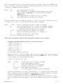
TP4-WT4
Serial Communications Output Addendum
AMALGAMATED INSTRUMENT CO PTY LTD
Unit 5, 28 Leighton Place Hornsby
NSW 2077 Australia
Telephone: +61 2 9476 2244
Facsimile: +61 2 9476 2902
ACN: 001 589 439
e-mail: [email protected]
Internet: www.aicpl.com.au
Table of Contents
1 Introduction
3
2 RS232/RS485 commands
4
3 Modbus RTU functions
11
4 Data logger
16
2 of 19
TPWTADD-1.4-0
1
Introduction
This addendum to the main TP4-WT4 manual contains information for the operation of the serial
communications including Modbus and Data logger commands. Refer to the main TP4-WT4
manual for all other information regarding this instrument.
An ASCII conversion table is provided in section 4.1 page 19.
1.1
Serial communications connections
When using the standard RS232 output link LK8 must be in, Tx at the TP4 end connects to Rx
at the other end of the serial link, likewise Rx at the TP4 end connects to Tx at the other end of
the link. When using the optional RS485 connections are A the TP4 end to A at the other end of
the link and B at the TP4 end to B at the other end. The ground line should be connected in each
case. If the TP4 is the first or last unit in a RS485 chain then the link LK7 may need to be in, this
places a terminating resistor across the input to help prevent signal reflections in long cable runs.
Standard PC 9 pin male "D" type RS232 serial port connector.
Rear terminals (solder side) shown.
GND
5
5
9
3
3
2
4
Rx
Tx
7
Rx
Tx
8
Display
2
25 way "D" connectors:
7 = GND
2 = Rx
3 = Tx
6
1
RS485 connection terminals may vary, check documentation when connecting.
Terminal A is sometimes labeled "+" and terminal B is sometimes labeled "-"
TPWTADD-1.4-0
3 of 19
2
RS232/RS485 commands
RS232/485 Operation and Commands
When sending commands to make changes to function settings such as alarm setpoints the TP4
should be in normal measure mode when the command is sent i.e. display has been powered up
without any pushbuttons being pressed and FUNC mode not entered.
The dISP Cont, POLL, t.Prt and C.ALL operation modes are described in this chapter.
Refer to the separate Modbus chapter for details of the M.buS mode. Refer to the main instruction
manual and the separate user guide for A.buS, dSP.4 and dSP.6 mode description.
diSP - Image Display Mode:
In image display mode the display value is sent via RS232/RS485 as raw data in the format
< ESC > IXYYYYYY
Where:
< ESC >
I
X
YYYYYY
is
is
is
is
the
the
the
the
ESCAPE character (27 Dec, 1B Hex, ∧[ ASCII)
character “I” (73 Dec, 49 Hex)
number of image bytes in ASCII (31 to 38 Hex)
raw, 8 bit display data.
This information is output every display update (approx. 4 times per second - depending upon
baud rate). The number of image bytes sent depends on the number of display digits present. This
mode is suitable only when the receiving unit is produced by the same manufacturer as the TP4.
The most common usage would be to provide a large digit display for wide area viewing which
mimics the smaller display on the measuring instrument. The large digit displays automatically
detects the image mode data and displays the correct value accordingly. The data sent is seven
segment display image i.e. Bit 0 is segment A, Bit 1 is segment B etc.
Cont - Continuous Transmit Mode:
In this mode the display value is continually transmitted out via the RS232/485 interface in ASCII
format with 8 data bits + 1 stop bit. Data will be updated at approximately the same rate
as the sample rate selected (see RAtE function). In scanning (SCAN) mode channel 1 will be
retransmitted. See also C.ALL mode for continuous output of all channels. The format for this
mode is < ST X > XY Y Y Y Y Y < CR >
Where:
< ST X >
X
X
YYYYYY
< CR >
is start of text character (2 Dec, 02 Hex, ∧B ASCII)
SPACE (32 Dec, 20 Hex) for a positive value
“-” (45 Dec, 2D Hex) for a negative value
is the display value in ASCII
is a Carriage Return (13 Dec, 0D Hex, ∧M ASCII)
e.g.: If the display is showing 123456 then the instrument will send “02 31 32 33 34 35 36 0D”
(HEX) to the host. In arithmetic (Arth) mode the sum channel (Ch0) will be transmitted.
POLL - Host Controlled Transmit Mode:
This mode requires a host computer, PLC or other device to poll the instrument to obtain display
or other information or reset various setpoint parameters. Special communications software is
required when using POLL mode. Data is in ASCII format with 8 data bits + 1 stop bit. When
polling the TP4 it is essential that the command characters are sent with less than a 10mS delay
between them. This normally means that each command line must be sent as a whole string e.g.
< ST X > P A < CR > is sent as one string rather than < ST X > on one line followed by P etc.
4 of 19
TPWTADD-1.4-0
Whenever the function key is operated the whole string is sent. The format used is ASCII (8 data
bits + 1 stop bit) so for instance if address 1 is used then the string < ST X > P A < CR > may
be put into a terminal program as ∧BP!∧M
Where:
∧B
P
!
∧M
is the ASCII character for STX
is the command line to transmit the primary display value (Ch0)
value in arithmetic (Arth) mode or (Ch 1) value in scanning
(SCAN) mode
is the ASCII character for address 1 (33 Dec of 21 Hex)
is the ASCII character for CR (13 Dec, 0D Hex)
A typical format for the host command is as follows:- < ST X > CA < CR > (Standard read etc.)
or < ST X > CA < CR > N < CR >XYYYYYY (Set Value Command)
Where:
< ST X > is Start of Text Character (2 Dec, 02 Hex, ∧B ASCII)
C
is the command character (see following poll commands available)
A
is the unit address (Range: 32 to 63 Dec, 20 to 3F Hex, “SPACE”
to ? ASCII the address is offset by 32 Dec, 20 Hex)
< CR >
is Carriage Return (13 Dec, 0D Hex, ∧M ASCII)
N
is the setpoint number in ASCII e.g.: 1 for alarm 1 etc.
X
SPACE for positive and “-” for negative
Y Y Y Y Y Y is the setpoint value in ASCII
The POLL commands available and instrument responses are as follows:
1. Transmit individual channel values or all channel values:
< ST X
< ST X
< ST X
< ST X
< ST X
< ST X
> P A < CR > or
> 1A < CR > or
> 2A < CR > or
> 3A < CR > or
> 4A < CR > or
> QA < CR >
e.g. ∧B2!∧M for channel 2 (address 1).
Instructs the unit to return the display value for selected channel. If P is selected then in
arithmetic mode the sum channel (Ch0) will be returned, in SCAN mode. Use 1 for channel
1, 2 for channel 2 etc. The returned data will be:
< ACK > N AXY Y Y Y Y Y < CR >
Where:
< ACK >
N
A
X
YYYYYY
< CR >
is Acknowledge (6 Dec, 06 Hex, ∧F ASCII)
is the channel number in ASCII
is the responding unit’s address in ASCII
SPACE for positive and “-” for negative
is the display value in ASCII
is a Carriage Return (13 Dec, 0D Hex, ∧M ASCII)
For all active channels use “Q” instead of the channel no. e.g. ∧BQ!∧M. The returned values
will be: channel 0 (total if in arithmetic mode), channel 1, channel 2, channel 3, channel 4
(only active channels will be returned - see SCAN CHLS function) i.e.:
< ACK > QAXY Y Y Y Y Y, XY Y Y Y Y Y, XY Y Y Y Y Y, XY Y Y Y Y Y, XY Y Y Y Y Y < CR >
If set for scanning rather than arithmetic operation the channel 0 value will not be transmitted.
TPWTADD-1.4-0
5 of 19
2. Transmit Secondary Display Value:
< ST X > SA < CR > e.g. ∧BS!∧M using (address 1).
Instructs the unit to send the secondary display value. The value will equal the primary
display value (< ST X > SA < CR > command) if the R.INP function is set to NONE. If
the R.INP function is set to Hi, Lo, HiLo, P.HLd or d.HLd the value for the selected
operation will be returned (note: For HiLo the Hi value followed by the Lo value will be
sent separated by a comma). In arithmetic mode the peak high and peak low values output
will be for channel 0 i.e. the result. In scanning mode the peak high and peak low values
sent are for channel 1 only. Format of returned data is:
< ACK > SAY Y Y Y Y Y < CR > or < ACK > SAY Y Y Y Y Y, Y Y Y Y Y Y < CR >
in the case of HiLo
Where:
< ACK >
S
A
YYYYYY
< CR >
is Acknowledge (6 Dec, 06 Hex, ∧F ASCII)
echo command received “S” (83 Dec, 53 Hex)
is the responding unit’s address
is the secondary display value in ASCII
is a Carriage Return (13 Dec, 0D Hex, ∧M ASCII)
3. Reset Special Function Value:
< ST X > RA < CR > e.g. ∧BR#∧M (address 3).
Instructs the unit to reset the special function value set via the R.INP function (if applicable).
Will reset the stored value for Peak Hold, Valley High and Valley Low or will operate the
selected special function (tare, zero or batch functions only). Format of returned data is:< ACK > RA < CR >
Where:
< ACK >
R
< CR >
is Acknowledge (6 Dec, 06 Hex, ∧F ASCII)
echo command received “R” (82 Dec, 52 Hex)
is a Carriage Return (13 Dec, 0D Hex, ∧M ASCII)
If special functions are not active then the invalid command message will be returned (refer
“Invalid Command” later). The tare command will only operate in arithmetic mode and will
tare all channels including channel 0. The zero command will zero all channels in arithmetic
mode, in scanning mode the channel shown on the display at the time of the command being
received will be zeroed.
4. Zero Selected Channel:
< ST X > ZA < CR >< N >< CR >
e.g. ∧BZ!∧M3∧M will cause channel 3 to zero in the instrument with address 1. Note that
the channel being zeroed needs to be connected to a live input at the time this command is
sent. The zero command will not be successful if the display value at the time is outside the
zero range for the channel selected, see Ch1 Z.rnG function in the main instruction manual
for further description. Instructs the unit to zero the display value for the selected instrument
and channel. Format of returned data is:< ACK > ZA < CR >
Where:
6 of 19
< ACK >
Z
A
< CR >
is
is
is
is
Acknowledge (6 Dec, 06 Hex, ∧F ASCII)
echo command received “Z” (90 Dec, 5A Hex)
the responding unit’s address
a Carriage Return (13 Dec, 0D Hex, ∧M ASCII)
TPWTADD-1.4-0
5. Read low alarm setpoint: < ST X > LA < CR > N < CR >
e.g. ∧BN!∧M2∧M to read alarm 2 low setpoint using a terminal program (address 1). Instructs unit to return the low alarm setpoint value. Format of returned data is:
< ACK > LAN XY Y Y Y Y < CR >
Where:
< ACK > is Acknowledge (6 Dec, 06 Hex, ∧F ASCII)
L
echo command received “L” (76 Dec, 4C Hex)
A
is the responding units address
N
is the relay number in ASCII
X
SPACE for positive and “-” for negative
YYYYY
is the setpoint value in ASCII
< CR >
is a Carriage Return (13 Dec, 0D Hex, ∧M ASCII)
6. Read high alarm setpoint: < ST X > HA < CR > N < CR >
e.g. ∧HN!∧M2∧M to read alarm 2 high setpoint using a terminal program (address 1).
Instructs unit to return the high alarm setpoint value. Format of returned data is: < ACK >
HAN XY Y Y Y Y < CR >
Where:
< ACK >
H
A
N
X
YYYYY
< CR >
is Acknowledge (6 Dec, 06 Hex, ∧F ASCII)
echo command received “H” (72 Dec, 48 Hex)
is the responding units address
is the relay number in ASCII
SPACE for positive and “-” for negative
is the setpoint value in ASCII
is a Carriage Return (13 Dec, 0D Hex, ∧M ASCII)
7. Set low alarm setpoint: < ST X > lA < CR > N < CR > XY Y Y Y Y < CR >
e.g. ∧lN!∧M1∧M1000∧ to set alarm 1 low setpoint to 1000 using a terminal program (address
1). Instructs unit to set the low alarm setpoint value.
Format of returned data is: < ACK > lAN XY Y Y Y Y < CR >
Where:
< ACK >
l
A
N
X
YYYYY
< CR > is a
is Acknowledge (6 Dec, 06 Hex, ∧F ASCII)
echo command received “l” (108 Dec, 6C Hex)
is the responding units address
is the relay number in ASCII
SPACE for positive and “-” for negative
is the setpoint value in ASCII
Carriage Return (13 Dec, 0D Hex, ∧M ASCII)
8. Set high alarm setpoint: < ST X > hA < CR > N < CR > XY Y Y Y Y < CR >
e.g. ∧hN!∧M1∧M5000∧ to set alarm 1 low setpoint to 5000 using a terminal program (address
1). Instructs unit to set the high alarm setpoint value. Format of returned data is: < ACK >
hAN XY Y Y Y Y < CR >
Where:
TPWTADD-1.4-0
< ACK >
h
A
N
X
is Acknowledge (6 Dec, 06 Hex, ∧F ASCII)
echo command received “h” (104 Dec, 68 Hex)
is the responding units address
is the relay number in ASCII
SPACE for positive and “-” for negative
7 of 19
YYYYY
< CR >
is the setpoint value in ASCII
is a Carriage Return (13 Dec, 0D Hex, ∧M ASCII)
9. Set Offset Value:
< ST X > OA < CR >< N >< CR > XY Y Y Y Y Y < CR >
e.g. ∧BO!∧M3∧M50∧M to force the current mV input on channel 3 to be displayed as
50 (address 1). Note that the channel being whose reading is being changed needs to be
connected to a live input at the time this command is sent. The new value will cause an
offset in the display readings across the scale. For example if the value sent by this command is
50 and the value on the display prior to the value of 50 being sent was 40 then a value of 10 will
be added across the whole display range for that channel. Instructs unit to change the display
value for the channel selected. Format of returned data is:- < ACK > OAN XY Y Y Y Y Y <
CR >
Where:
< ACK >
O
A
N
X
YYYYYY
< CR >
is Acknowledge (6 Dec, 06 Hex, ∧F ASCII)
echo command received “O” (79 Dec, 4F Hex)
is the responding units address
is the channel number in ASCII
is SPACE for positive and “-” for negative
is the new display value in ASCII
is a Carriage Return (13 Dec, 0D Hex, ∧M ASCII)
10. Read the ECAL and ESCL values:
< ST X > eA < CR >< N >< CR >
e.g. ∧Be!∧M3∧M to ask the TP4 to return the ECAL and ESCL values for channel 3
(address 1). Instructs unit to read back the ECAL and ESCL values. Format of returned
data is:- < ACK > eAN XY Y Y.Y Y Y, XZZZZZZ < CR >
Where:
< ACK >
e
A
N
X
Y Y Y.Y Y Y
X
ZZZZZZ
< CR >
is Acknowledge (6 Dec, 06 Hex, ∧F ASCII)
echo command received “e” (101 Dec, 65 Hex)
is the responding units address
is the channel number in ASCII
is SPACE for positive and “-” for negative
is the ECAL value in ASCII, always to 3 decimal places
is SPACE for positive and “-” for negative
is the ESCL value in ASCII
is a Carriage Return (13 Dec, 0D Hex, ∧M ASCII)
11. Set the ECAL and ESCL values:
< ST X > EA < CR >< N >< CR > XY Y Y.Y Y Y < CR > XZZZZZZ < CR >
e.g. ∧BE!∧M3∧M2.000∧M5000∧M sets the channel 3 ECAL value to 2.000 and the ESCL
value to 5000 (address 1). Note the ECAL and ESCL values simply set the slope of the
calibration curve, a definite reference point through which this slope passes such as a zero or
offset also needs to be set when using this method of calibration. The zero or offset can be
accomplished via the relevant serial commands listed in this chapter or may be done at the
TP4 itself. The ECAL value set must be within the value set at the RNGE function for that
channel e.g. you cannot set the ECAL to 2.000 if the RNGE function is set to 1.000. The
maximum positive and negative values to which the ECAL value can be successfully set are
-32.000 to 32.000 this applies even when the RNGE setting is 100. If an input with a
8 of 19
TPWTADD-1.4-0
higher mV/V output is being used then the ECAL and ESCL values can be set in correct
ratios to accomplish the requires setting e.g. an ECAL value of 50.000 and ESCL of 1000
cannot be set but an ECAL of 25.00 and ESCL of 500 will set the same calibration slope
and will give the correct reading at 50.000mV/V input. Instructs unit to set the ECAL and
ESCL values. Format of returned data is:
< ACK > EAN XY Y Y.Y Y Y, XZZZZZZ < CR >
Where:
< ACK >
E
A
N
X
Y Y Y.Y Y Y
X
ZZZZZZ
< CR >
is Acknowledge (6 Dec, 06 Hex, ∧F ASCII)
echo command received “E” (69 Dec, 45 Hex)
is the responding units address
is the channel number in ASCII
is SPACE for positive and “-” for negative
is the ECAL value in ASCII, always to 3 decimal places
is SPACE for positive and “-” for negative
is the ESCL value in ASCII
is a Carriage Return (13 Dec, 0D Hex, ∧M ASCII)
12. Transmit instrument model and software version: < ST X > IA < CR > e.g.
∧BI!∧M using a terminal program (address 1). Instructs unit to return the instrument
model and software version.
Format of returned data is: < ACK > IACCX.X < CR >
Where:
< ACK >
I
A
CC
X.X
< CR >
is Acknowledge (6 Dec, 06 Hex, ∧F ASCII)
echo command received “I” (73 Dec, 49 Hex)
is the responding units address (offset by 32 Dec e.g. “!” is address 1)
a 2 character identifier e.g. LC means loadcell input
is the software version number e.g. 4.6
is a Carriage Return (13 Dec, 0D Hex, ∧M ASCII)
13. Invalid command: If the command received from the host is invalid the unit will return
the following: < ACK >?A < CR >, where:
Where:
< ACK >
?
A
< CR >
is Acknowledge (6 Dec, 06 Hex, ∧F ASCII)
echo command received “?” (63 Dec, 3F Hex)
is the responding units address (offset by 32 Dec e.g. “!” is address 1)
is a Carriage Return (13 Dec, 0D Hex, ∧M ASCII)
t.Prt mode
The display values for the active input channels can be sent in ASCII format from the serial port
at programmable regular time periods for output to a serial printer, PLC or computer. The PRNt
SECS function allows the time period for the print output to be set. The available range is from
1 to 7200 seconds. For example if set to 10 seconds the TP4 will send the channel information via
the serial port every 10 seconds. To access and use this output method the O.Put function must
be set to t.Prt.
A typical format for four active channels in scanning mode is:
CH1
855, CH2
845, CH3
859, CH4
845
A typical format for four active channels in arithmetic mode is:
TOTAL
3404, CH1
855, CH2
845, CH3
859, CH4
845
Each output string is preceded by a start of text character <STX> and ends in a carriage return
<CR>
TPWTADD-1.4-0
9 of 19
C.ALL mode
This mode operates in the same manner as the Cont mode except that all active channels are
transmitted. In scanning mode channel 1 is the first channel to be transmitted. In arithmetic mode
operation the result is transmitted first followed by channel 1 etc. A typical format for the data
would be:
<STX>
90,
30,
0,
40,
20 <CR>
Where 90 is the result, 30 is channel 1 value, 0 is channel 2 value etc.
10 of 19
TPWTADD-1.4-0
3
Modbus RTU functions
When using Modbus RTU communications the instrument must be set up electrically for RS232
or RS485 communications and the function must be set to M.bus. The maximum recommended
baud rate for Modbus operation is 9600. The following commands are available:
Modbus Function 1 - Read coil status
Reads the ON/OFF status of the relay coils. Broadcast is not supported. Relay addresses are
offset by 1 e.g. relay 1 is addressed as 0, relay 2 is addressed as 1 etc. Logic 1 = ON, Logic 0 =
OFF. To read the coil status a query is sent to the instrument, the instrument then responds to
the query. An example of a query to read coils 1 to 4 from the instrument at address 2 is given
below.
Field name
Unit address
Function
Starting address Hi
Starting address Lo
Number of points Hi
Number of points Lo
Error check (LRC or CRC)
An example of a response is given below:
Field name
Unit address
Function
Byte count
Data (coils 4 to 1)
Error check (LRC or CRC)
Example(Hex)
02
01
00
00
00
04
–
Example(Hex)
02
01
01
04
–
The status of the relay coils is shown in the Data 04 (hex) or binary 0100. Relay 1 is indicated by
the least significant binary bit. The status of the relays is therefore:
Relay 4 - OFF, Relay 3 - ON, Relay 2 - OFF, Relay 1 - OFF
Function 3 - Read holding registers
This function reads the binary contents of the holding registers in the instrument being addressed.
The value for this function is stored as a 32 but two’s compliment number in two 16 bit registers
per channel. Note; a value of 1,000,000 represents a positive overrange and -200,000 a negative
overrange.
Registers 1 to 8 are addressed as 0X00 to 0X07.
Registers 9 to 16 hold the alarm high values for relays 1 to 4. Note a value of 0X80000000 means
that the relay is set to OFF and has no high value. Registers 9 to 16 are addressed as 0X08 to
0X0F.
Registers 17 to 20 hold the alarm low values for relays 1 to 4. Note a value of 0X80000000 means
that the relay is set to OFF and has no low value. Registers 17 to 24 are addressed as 0X10 to
0X17.
Registers 25 to 28 represent the decimal point settings for channels 1 to 4. Registers 25 to 28 are
addressed as 0X18 to 0X1B.
TPWTADD-1.4-0
11 of 19
An example of a query to read input channels 1 and 2 from an instrument at address 5 is given
below.
Field name
Unit address
Function
Starting address Hi
Starting address Lo
Number of points Hi
Number of points Lo
Error check (LRC or CRC)
Example(Hex)
05
03
00
00
00
04
–
An example of a response is given below:
Field name
Unit address
Function
Byte count
Data Hi(register 1)
Data Lo(register 1)
Data Hi(register 2)
Data Lo(register 2)
Data Hi(register 3)
Data Lo(register 3)
Data Hi(register 4)
Data Lo(register 4)
Error check (LRC or CRC)
Example(Hex)
05
03
08
00
01
86
A0
FF
FF
DB
F0
–
The value of channel 1 is 000186A0 which is 100,000. The value of channel 2 is FFFFD8F0 which
is -10,000. Note: Two registers should be read at a time to get both halves of the 32 bit value.
12 of 19
TPWTADD-1.4-0
Register table for TP4-WT4 displays using Modbus RTU function 3
Address Register Description
0X00
1
Channel 1 high word
0X01
2
Channel 1 low word
0X02
3
Channel 2 high word
0X03
4
Channel 2 low word
0X04
5
Channel 3 high word
0X05
6
Channel 3 low word
0X06
7
Channel 4 high word
0X07
8
Channel 4 low word
0X08
9
Relay 1 high setpoint high word
0X09
10
Relay 1 high setpoint low word
0X0A
11
Relay 2 high setpoint high word
0X0B
12
Relay 2 high setpoint low word
0X0C
13
Relay 3 high setpoint high word
0X0D
14
Relay 3 high setpoint low word
0X0E
15
Relay 4 high setpoint high word
0X0F
16
Relay 4 high setpoint low word
0X10
17
Relay 1 low setpoint high word
0X11
18
Relay 1 low setpoint low word
0X12
19
Relay 2 low setpoint high word
0X13
20
Relay 2 low setpoint low word
0X14
21
Relay 3 low setpoint high word
0X15
22
Relay 3 low setpoint low word
0X17
23
Relay 4 low setpoint high word
0X17
24
Relay 4 low setpoint low word
0X18
25
Channel 0 (arithmetic sum) decimal point - arithmetic mode only
0X19
26
Channel 1 decimal point
0X1A
27
Channel 2 decimal point
0X1B
28
Channel 3 decimal point
0X1C
29
Channel 4 decimal point
0X20
33
Channel 0 (arithmetic sum) high word - arithmetic mode only
0X21
34
Channel 0 (arithmetic sum) LOW word - arithmetic mode only
0X200
513
Channel 1 offset high word
0X201
514
Channel 1 offset low word
0X202
515
Channel 2 offset high word
0X203
516
Channel 2 offset low word
0X204
517
Channel 3 offset high word
0X205
518
Channel 3 offset low word
0X206
519
Channel 4 offset high word
0X207
520
Channel 4 offset low word
TPWTADD-1.4-0
13 of 19
Function 6 - Preset single register and Function 16 - Preset multiple registers
The registers for these modes are shown below. The offset commands allow any valid display value
to be set for each input channel. To zero the channel selected the offset high word and low word
should be set to zero. The registers are 16 bit, if the offset value is betwen 0 and 65535 then the
offset can if required be entered using the low word only. To change the offset value send the new
value you wish that channel to be e.g. If channel 1 reads 2 and you wish it to read 5 send the value
5. Note that offsets are also affected by the zero range function. If an offset is not accepted due to
the zero range setting the instrument will show the error message ZERO RNGE ERR.
Address
0X200
0X201
0X202
0X203
0X204
0X205
0X206
0X207
Register
513
514
515
516
517
518
519
520
Description
Channel 1 offset high word (function 6) or Channel 1 offset (function 16)
Channel 1 offset low word (function 6 only)
Channel 2 offset high word (function 6) or Channel 2 offset (function 16)
Channel 2 offset low word (function 6 only)
Channel 3 offset high word (function 6) or Channel 3 offset (function 16)
Channel 3 offset low word (function 6 only)
Channel 4 offset high word (function 6) or Channel 4 offset (function 16)
Channel 4 offset low word (function 6 only)
An example of using function 6 to set Channel 1 offset to 2C (44 dec.) at an instrument with
address 2 is:
Field name
Unit address (node number)
Function
Register address Hi
Register address Lo
Data Hi
Data Lo
Error check (LRC or CRC)
Example(Hex)
02
06
02
00
00
2C
–
An example of a function 6 response is given below:
Field name
Unit address (node number)
Function
Register address Hi
Register address Lo
Data Hi
Data Lo
Error check (LRC or CRC)
Example(Hex)
02
06
02
00
00
2C
–
An example of using function 16 to set Channel 1 offset to 2C (44 dec.) and Channel 2 offset to
50 (80 dec.) at an instrument with address 2 is:
14 of 19
TPWTADD-1.4-0
Field name
Unit address (node number)
Function
Register address Hi
Register address Lo
Number of registers Hi
Number of registers Lo
Byte count
Data Hi
Data Lo
Data Hi
Data Lo
Error check (LRC or CRC)
Example(Hex)
02
10
02
00
00
02
04
00
2C
00
50
–
An example of a function 16 response is as follows
Field name
Unit address (node number)
Function
Register address Hi
Register address Lo
Number of registers Hi
Number of registers Lo
Error check (LRC or CRC)
TPWTADD-1.4-0
Example(Hex)
02
10
02
00
00
02
–
15 of 19
4
Data logger
The data logger is an optional addition to the instrument. This section applies only to instruments
fitted with the data logger option. If the data logger is being used with the Windows compatible
software provided then refer to the separate “Download Software User Guide” booklet.
Operation of the data logger
The data logger memory will store the hours:mins:secs, day:month and year together with the
display reading at the time of log update. The log update time may be set at the Log UPdt
function. If an input is overranged when logged then the overrange value (- - - -) will be logged
for that channel for as long as the overrange value is present. Readings taken during power failure
will not be logged. The log memory is set up in a circular format. Once the top of memory is reached
the log data will overwrite the start of memory (overwriting the oldest record). The recording time
available will vary depending on the memory size fitted and the update time selected. The table
below shows maximum recording times.
Data is transmitted in comma separated format making it compatible with many commercially
available databases/spreadsheets. Time information is downloaded in Julian time format which
is again compatible with many databases/spreadsheets. The internal clock is battery backed.
Downloaded log records are in the form of the time followed by the logged record for each channel
at that time.
Downloaded information is transmitted via the serial output option board in RS232 or RS485
format, thus a serial output option must be fitted on all instruments with data logging software.
Data logger Windows software
Data logger software compatible with Windows 95, 98, 2000, NT and XP is provided for use with
the data logger (not tested and may not be compatible with Vista). A separate user booklet for the
software is also provided. Consult this user manual for details of software setup. The data logger
can also communicate using standard serial polling commands, these are listed under the heading
“Serial Command Format” in this chapter.
TP4-WT4 datalogger table - maximum logging times (approximate)
Time between logs
32k memory
128k memory
days:hours:min
days:hours:min
10 seconds
0:04:39
0:18:37
20 seconds
0:09:18
1:13:13
30 seconds
0:13:57
2:07:50
1 minute
1:03:54
4:15:40
2 minutes
2:07:48
9:08:20
3 minutes
3:11:42
14:00:00
4 minutes
4:15:36
18:16:40
5 minutes
5:19:30
23:08:20
6 minutes
6:23:24
27:01:00
10 minutes
11:15:00
46:16:40
15 minutes
17:14:30
70:01:00
20 minutes
23:06:00
93:09:20
30 minutes
34:21:00
140:02:00
60 minutes
69:18:00
280:04:00
Data logger polling functions
Usually data is downloaded using the Windows program supplied with the data logger but the data
logger can be also polled via a PC etc. using the commands below. Functions which are used when
16 of 19
TPWTADD-1.4-0
the data logger option is fitted are accessible only via CAL mode.
LoG UPdt (select log update time) Displays and sets the time period between each log sample.
Available selections are: 0.10 (10 seconds), 0.20 (20 seconds), 0.30 (30 seconds), 1.00 (1
minute), 2.00 (2 minutes), 3.00 (3 minutes), 4.00 (4 minutes), 5.00 (5 minutes), 6.00
(6 minutes), 10.00 (10 minutes), 15.00 (15 minutes), 20.00 (20 minutes), 30.00 (30
minutes) or 60.00 (60 minutes).
Note: The data log memory (see CLr Log below) must be cleared whenever the log update
time is changed or the date and time is changed.
CLr Log (clear data log memory) This function clears the data log memory, to clear the memory
press then release ^ and v simultaneously, the display will show CIr? asking if you really
want to clear the memory. If you wish to clear memory then press then release ^ and v
simultaneously again. The log memory will then be cleared and the log period reset, the
display will indicate Prog Log to confirm this. Once the memory is cleared all previously
logged records will be lost from the instruments memory, if the CIr? message is reached
and it is not wished to clear the log memory then pressing and releasing either F or P will
abort the function.
Set rtc (set time) Displays and sets the current time in hours and minutes (24 hour format
HH.MM) e.g. set as 1720 for 5:20 pm.
Set dAtE (set date) Displays and sets the current date in days and months (DD.MM format).
The months will roll over automatically (up at the end of the month, down at the beginning
of the month) as the day is scrolled up or down.
Set YEAR (set year) Displays and sets the current year (YYYY format). Valid years settings
go up to 2037 (valid Julian time format years).
Serial Command Format
Instruments using the data logger option are provided with extra software functions to the standard
instrument. This section describes these extra functions.
Initial Setup
Select the baud rate, parity and address as required. The serial output mode function (O.Put)
must be set to POLL when using the data logger.
Transmit Record Block: <STX>DA<CR>D<CR>TTTTTTTTTT<CR>NNNN<CR>
Where: TTTTTTTTTT is the start time of the block (in Julian time format). NNNN is the
number of records to be sent. Instructs the unit to send a block of logged data via the serial
interface. The returned data format is: <ACK>DAD<CR> followed by NNNN records in
the format:TTTTTTTTTT,S1111,S2222,S3333,S4444,S5555,S6666,S7777,S8888<CR> where:
TTTTTTTTTT is the start time for each record (in Julian time format). If TTTTTTTTTT
(time in “Transmit Record Block” request) is sent as 0 then the records will start at the
earliest time in log memory.
S is the sign (<SPACE> for positive values and “-” for negative.)
1111, 2222 etc. are the values for each channel.
Values will only be transmitted for active channels. Invalid readings from any channel will be
received as the overrange value (- - - -) for that channel. If the start time requested is not
present in the log then <ACK>DA?<CR> will be returned.
TPWTADD-1.4-0
17 of 19
Transmit All Logged Data: <STX>DA<CR>A<CR>
Instructs the unit to transmit the entire data log. All log records since the last log memory
reset will be sent to the host. The unit will respond with <ACK>DAA<CR> followed by
all log record sent in the same format as above (Transmit Record Block)
Transmit System Time: <STX>DA<CR>T<CR>
Instructs the instrument to transmit the current time in Julian time format as follows:<ACK>DAT TTTTTTTTTT<CR>
Transmit the Log Start Time: <STX>DA<CR>S<CR>
Instructs the instrument to transmit the log start time i.e. the time stamp on the first record
in the log. Note that if the memory has “wrapped around”, i.e. has started to overwrite
existing logged records, that the log start time will not be the original time the log started
(since this time stamp and associated log record has been overwritten). The returned data
format is: <ACK>DAS TTTTTTTTTT<CR>
Transmit the Log Update Time: <STX>DA<CR>U<CR>
Returns the current log update time as set in the log memory. The returned time may be
different to the dLAY time if there has been no log reset since the dLAY function was
changed. The returned data format is: <ACK>DAU NNNN<CR>, where NNNN is the
update time in seconds.
Transmit the Log Memory Size: <STX>DA<CR>M<CR> Returns the size of the log memory in records. The returned data format is: <ACK>DAM NNNN<CR>, where NNNN is
the number of records for that memory size e.g. an 8K memory will return 508.
Set the System Time: <STX>DA<CR>t<CR>TTTTTTTTTT<CR>
Set the instrument system clock to Julian time TTTTTTTTTT. If the command is successful
then <ACK>DAt<CR> will be returned. If the Julian time is invalid then <ACK>DA?<CR>
will be returned.
Set the Log Update Time: <STX>DA<CR>u<CR>NNNN<CR>
Set the log update time to NNNN seconds. Note that the new time will not apply until a log
reset is performed. If the command is successful then <ACK>DAu<CR> will be returned.
If the update time is invalid then <ACK>DA?<CR> will be returned. Valid times are as
shown in the dLAY function explanation.
Reset the Log Memory: <STX>DA<CR>R<CR>RESET<CR>
This command will reset the log memory. This will erase all current records and reset the
log update time if it has changed. As this will result in a loss of data the command must
be sent exactly as it appears or the memory will not be reset. If the command is successful
then <ACK>DAR<CR> will be returned to indicate that the memory has been reset. If
the command is invalid then <ACK>DA?<CR> will be returned.
18 of 19
TPWTADD-1.4-0
4.1
ASCII Code Conversion Listing
ASCII for control characters is shown in brackets. e.g. STX may in some cases be entered as ∧B.
ASCII char.
Decimal
Hex
ASCII char.
Decimal
Hex
ASCII char.
Decimal
Hex
NUL (∧@)
SOH (∧A)
STX (∧B)
ETX (∧C)
EOT (∧D)
ENQ (∧E)
ACK (∧F)
BEL (∧G)
BS (∧H)
HT (∧I)
LF (∧J)
VT (∧K)
FF (∧L)
CR (∧M)
SO (∧N)
SI (∧O)
DLE (∧P)
DC1 (∧Q)
DC2 (∧R)
DC3 (∧S)
DC4 (∧T)
NAK (∧U)
SYN (∧V)
ETB (∧W)
CAN (∧X)
EM (∧Y)
SUB (∧Z)
ESC (∧[)
FS (∧\)
GS (∧∧)
RS (∧)
US (∧ )
SP ( )
!
”
#
$
%
&
’
(
)
∗
00
01
02
03
04
05
06
07
08
09
10
11
12
13
14
15
16
17
18
19
20
21
22
23
24
25
26
27
28
29
30
31
32
33
34
35
36
37
38
39
40
41
42
00
01
02
03
04
05
06
07
08
09
0A
0B
0C
0D
0E
0F
10
11
12
13
14
15
16
17
18
19
1A
1B
1C
1D
1E
1F
20
21
22
23
24
25
26
27
28
29
2A
+
,
.
/
0
1
2
3
4
5
6
7
8
9
:
;
<
=
>
?
@
A
B
C
D
E
F
G
H
I
J
K
L
M
N
O
P
Q
R
S
T
U
43
44
45
46
47
48
49
50
51
52
53
54
55
56
57
58
59
60
61
62
63
64
65
66
67
68
69
70
71
72
73
74
75
76
77
78
79
80
81
82
83
84
85
2B
2C
2D
2E
2F
30
31
32
33
34
35
36
37
38
39
3A
3B
3C
3D
3E
3F
40
41
42
43
44
45
46
47
48
49
4A
4B
4C
4D
4E
4F
50
51
52
53
54
55
V
W
X
Y
Z
[
\
]
∧
86
87
88
89
90
91
92
93
94
95
96
97
98
99
100
101
102
103
104
105
106
107
108
109
110
111
112
113
114
115
116
117
118
119
120
121
122
123
124
125
126
127
56
57
58
59
5A
5B
5C
5D
5E
5F
60
61
62
63
64
65
66
67
68
69
6A
6B
6C
6D
6E
6F
70
71
72
73
74
75
76
77
78
79
7A
7B
7C
7D
7E
7F
TPWTADD-1.4-0
‘
a
b
c
d
e
f
g
h
i
j
k
l
m
n
o
p
q
r
s
t
u
v
w
x
y
z
{
|
}
˜
DEL
19 of 19