1
T9000
DEVELOPMENT
TOOLS
Preliminary Datasheets
Si
SGS-1HOMSOII
~Irm ~D©OO@rn[brn©1jOO@~D©~
INMOS is a member of the SGS-THOMSON Microelectronics Group
INMOS transputer databook series
Transputer Databook
Military and Space Transputer Databook
Transputer Development and iq Systems Databook
Transputer Applications Notebook: Architecture and Software
Transputer Applications Notebook: Systems and Performance
T9000 Transputer Hardware Reference Manual
T9000 Transputer Instruction Set Manual
T9000 Development Tools - Preliminary Datasheets
INMOS reserves the right to make changes in specifications at any time and without notice. The information
furnished by INMOS in this publication is believed to be accurate; however, no responsibility is assumed for
its use, nor for any infringement of patents or other rights of third parties resulting from its use. No licence
is granted under any patents, trademarks or other rights of INMOS.
INMOS Limited 1993
• ,DmJmos", IMS, occam and OS-Link are trademarks of INMOS Limited.
~ ~~i@m~l~~~ is a registered trademark of the SGS-THOMSON Microelectronics Group.
INMOS Limited is a member of the SGS-THOMSON Microelectronics Group.
INMOS document number: 72 TRN 249 00
ORDER CODE:DBT9000DTST/1
I
Contents
Preface . . . . . . . . . . . . . . . . . . . . . . . . . . . . . . . . . . . . . . . . . . . . . . . . . . . . . . . . . . . . . .
iii
1 Introduction
1
1.1
Transputer modules. . . . . . . . . . . . . . . . . . . . . . . . . . . . . . . . . . . . . . . . . . . . . . . . . . . . . . . . .
1.2
IMS T9000 board products. . . . . . . . . . . . . . . . . . . . . . . . . . . . . . . . . . . . . . . . . . . . . . . . . . .
2
1.3
IMS T9000 software
3
2 IMS Ox394 T9000 ANSI C Toolset
2
5
2.1
Introduction. . . . . . . . . . . . . . . . . . . . . . . . . . . . . . . . . . . . . . . . . . . . . . . . . . . . . . . . . . . . . . . .
2.2
IMS T9000 networks
6
8
2.3
Parallel programming
9
2.4
Compiler and compilation tools
2.5
Libraries. . . . . . . . . . . . . . . . . . . . . . . . . . . . . . . . . . . . . . . . . . . . . . . . . . . . . . . . . . . . . . . . . . .
16
2.6
Configuration, initialization and loading
16
2.7
Connecting IMS T9000 networks to T2/T4/T8 networks. . . . . . . . . . . . . . . . . . . . . . . . . .
21
2.8
Product components
22
2.9
Product yariants . . . . . . . . . . . . . . . . . . . . . . . . . . . . . . . . . . . . . . . . . . . . . . . . . . . . . . . . . . . .
23
2.10
Problem reporting and field support
24
3 IMS Ox395 T9000 occam 2 Toolset . . . . . . . . . . . . . . . . . . . . . . . . . . . . . . . . . .
12
25
3.1
Introduction. . . . . . . . . . . . . . . . . . . . . . . . . . . . . . . . . . . . . . . . . . . . . . . . . . . . . . . . . . . . . . . .
26
3.2
IMS T9000 networks. . . . . . . . . . . . . . . . . . . . . . . . . . . . . . . . . . . . . . . . . . . . . . . . . . . . . . . .
28
3.3
Parallel programming
30
3.4
Compiler and compilation tools. . . . . . . . . . . . . . . . . . . . . . . . . . . . . . . . . . . . . . . . . . . . . . .
31
3.5
Libraries. . . . . . . . . . . . . . . . . . . . . . . . . . . . . . . . . . . . . . . . . . . . . . . . . . . . . . . . . . . . . . . . . . .
33
3.6
Configuration, initialization and loading
34
3.7
Connecting IMS T9000 networks to T2/T4/T8 networks. . . . . . . . . . . . . . . . . . . . . . . . . .
38
3.8
Product components
40
3.9
Product variants . . . . . . . . . . . . . . . . . . . . . . . . . . . . . . . . . . . . . . . . . . . . . . . . . . . . . . . . . . . .
40
3.10
Problem reporting and field support
42
4 IMS 04390 T9000 INQUEST
43
4.1
Product overview
4.2
Interactive windowing debugger
.................................................
44
44
4.3
Performance analysis tools
48
4.4
Product details
49
4.5
Problem reporting and field support
49
Contents
ii
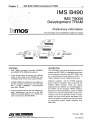
5 IMS 8490 T9000 Development TRAM. . . . . . . . . . . . . . . . . . . . . . . . . . . . . . . .
51
5.1
Introduction. . . . . . . . . . . . . . . . . . . . . . . . . . . . . . . . . . . . . . . . . . . . . . . . . . . . . . . . . . . . . . . .
5.2
IMS 8490 operation . . . . . . . . . . . . . . . . . . . . . . . . . . . . . . . . . . . . . . . . . . . . . . . . . . . . . . . . .
52
52
5.3
Support software
53
5.4
Hardware description
58
5.5
Pin descriptions
61
5.6
Mechanical details . . . . . . . . . . . . . . . . . . . . . . . . . . . . . . . . . . . . . . . . . . . . . . . . . . . . . . . . . .
62
5.7
Installation. . . . . . . . . . . . . . . . . . . . . . . . . . . . . . . . . . . . . . . . . . . . . . . . . . . . . . . . . . . . . . . . .
64
5.8
Specification. . . . . . . . . . . . . . . . . . . . . . . . . . . . . . . . . . . . . . . . . . . . . . . . . . . . . . . . . . . . . . .
65
5.9
Ordering Information
66
5.10
Field Support
66
5.11
References. . . . . . . . . . . . . . . . . . . . . . . . . . . . . . . . . . . . . . . . . . . . . . . . . . . . . . . . . . . . . . . .
66
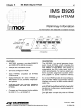
6 IMS 8926 4Mbyte HTRAM
67
6.1
Introduction. . . . . . . . . . . . . . . . . . . . . . . . . . . . . . . . . . . . . . . . . . . . . . . . . . . . . . . . . . . . . . . .
68
6.2
Specification. . . . . . . . . . . . . . . . . . . . . . . . . . . . . . . . . . . . . . . . . . . . . . . . . . . . . . . . . . . . . . .
70
6.3
Ordering Information
74
6.4
Field Support
74
6.5
References. . . . . . . . . . . . . . . . . . . . . . . . . . . . . . . . . . . . . . . . . . . . . . . . . . . . . . . . . . . . . . . .
74
7 IMS 8100 VME Format Motherboard
75
7.1
Introduction. . . . . . . . . . . . . . . . . . . . . . . . . . . . . . . . . . . . . . . . . . . . . . . . . . . . . . . . . . . . . . . .
76
7.2
Hardware Specification . . . . . . . . . . . . . . . . . . . . . . . . . . . . . . . . . . . . . . . . . . . . . . . . . . . . . .
78
7.3
Ordering Information
82
7.4
Field Support
82
7.5
References. . . . . . . . . . . . . . . . . . . . . . . . . . . . . . . . . . . . . . . . . . . . . . . . . . . . . . . . . . . . . . . .
83
A HTRAM specification
85
A.1
Introduction. . . . . . . . . . . . . . . . . . . . . . . . . . . . . . . . . . . . . . . . . . . . . . . . . . . . . . . . . . . . . . . .
86
A.2
Interface Signals
86
A.3
Dimensions. . . . . . . . . . . . . . . . . . . . . . . . . . . . . . . . . . . . . . . . . . . . . . . . . . . . . . . . . . . . . . . .
89
A.4
Pinout . . . . . . . . . . . . . . . . . . . . . . . . . . . . . . . . . . . . . . . . . . . . . . . . . . . . . . . . . . . . . . . . . . . . .
96
A.5
Power Supplies
101
A.6
Operating Environment . . . . . . . . . . . . . . . . . . . . . . . . . . . . . . . . . . . . . . . . . . . . . . . . . . . . . .
102
A.7
Initialization and 800tstrap . . . . . . . . . . . . . . . . . . . . . . . . . . . . . . . . . . . . . . . . . . . . . . . . . . .
102
A.8
Specification of HTRAMs
106
A.9
References. . . . . . . . . . . . . . . . . . . . . . . . . . . . . . . . . . . . . . . . . . . . . . . . . . . . . . . . . . . . . . . .
106
iii
Preface
This booklet describes the INMOS board hardware and software tools provided for development of
systems using IMS T9000 transputers. The products described are:
Software products
•
IMS Dx394 T9000 ANSI C Toolset
•
IMS Dx395 T9000 occam 2 Toolset
•
IMS 04390 T9000 INQUEST development environment
Board products
•
IMS 8490 T9000 Development TRAM
•
IMS 8926 4Mbyte HTRAM
•
IMS 8100 VME format HTRAM motherboard
The specification of the HTRAM format is included in an appendix.
iv
Preface
oOlJmos®
•
Chapter 1
Introduction
Introduction
1.1 Transputer modules
2
This document gives advance information about the IMS T9000 development systems. These products
are under continuing development and product details may change at any time without notice.
The new board and software products described in this booklet are suitable for constructing and program
ming IMS T9000 systems. An IMS T9000 system may use a single IMS T9000 or a network of IMS T9000
transputers.
1.1
Transputer modules
A module standard, the TRAM (TRAnsputer Module), was launched with the transputer to offer systems
developers a quick and easy way to build transputer development systems hardware. TRAMs are, in
effect, board-level transputers with a simple, standardized interface. They integrate processor, memory
and peripheral functions allowing powerful, flexible transputer-based systems to be produced with a
minimum of design effort. One or more TRAMs may be plugged into slots on a TRAM motherboard, which
may include an interface to a host. Thus single or multi-transputer systems may be built very quickly from
a range of standard products.
1.2
IMS T9000 board products
The IMS T9000 offers a much enhanced communications architecture using the new links, called
DS-Links (Data/Strobe). These links cannot be directly connected to IMS T2xx / T4xx / T8xx transputer
networks, which use OS-Links (Over Sampled). In order to take full advantage of the new communications
architecture, new board-level hardware and software development tools will be introduced which function
alongside existing hardware and software. It is envisaged that IMS T9000 users will adopt one of the
following options:
•
Use only IMS T9000 family devices.
•
Connect an IMS T2xx!T4xx!T8xx network to an IMS T9000 family network, using an IMS C1 00
system protocol converter as a gateway between the networks.
•
8uild an IMS T9000 network with IMS T2xx/T4xx/T8xx products as peripherals, using IMS C1 00
system protocol converters as interfaces.
INMOS is introducing a range of IMS T9000 products based on the existing TRAM standard to minimize
the cost for existing transputer users. A new HTRAM (High performance TRAnsputer Module) standard
has been defined to obtain optimal performance from the IMS T9000 super-scalar processor and
enhanced communications architecture. A range of HTRAM modules and motherboards is being
introduced.
Several host / transputer interfaces are available based on the TRAM standard. New HTRAM format
motherboards with host interfaces will also be introduced. In the meantime, the IMS 8490 T9000 Develop
ment TRAM (described below) can be used within TRAM-based systems to give a host / IMS T9000
interface.
1.2.1
IMS 8490 T9000 Development TRAM
The IMS 8490 T9000 Development TRAM is the primary board-level product for IMS T9000 development
systems. It provides quick and easy IMS T9000 access using anyone of the range of existing TRAM
based architectures. The T9000 Development TRAM can be:
•
used alone, for developing single IMS T9000 applications
•
used to allow a host to control and communicate with an IMS T9000 network or
•
used as an element of a TRAM-based network.
The T9000 Development TRAM will plug directly into existing TRAM motherboard slots. It may be used
as a single processor or as an element of a TRAM network. In addition, the DS-Links (including the control
1 Introduction
3
links) from the IMS T9000 transputer are brought out from IMS 8490 T9000 Development TRAM using
on-board hardware connectors. The IMS T9000 on the IMS 8490 T9000 Development TRAM can be thus
connected externally using OS-Link flying leads to other IMS T9000 transputers. A network of IMS T9000
transputers may be built by connecting together the OS-Links on several T9000 Development TRAMs
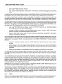
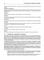
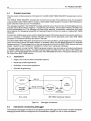
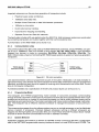
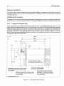
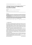
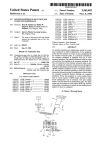
A single T9000 Development TRAM can be used as an interface to an HTRAM network or custom-built
IMS T9000 hardware. Typically, a host / IMS T9000 interface would consist of a T9000 Development
TRAM and a host / transputer interface which provides OS-Links, such as the IMS 8008 PC TRAM
Motherboard or IMS 8300 Ethernet to Transputer Gateway. Together, these provide a host / IMS T9000
interface with separate control and data link connections.
Host
- -
- -
Host!
transputer .
interface OS-Link
Figure 1.1
IMS 8490
T9000
Development
OS-Links
TRAM
-- -
IMS T9000
network
A host / IMS T9000 interface
The IMS 8490 T9000 Development TRAM and accompanying software are fully described in Chapter 5.
HTRAMs
1.2.2
HTRAM (High performance TRAnsputer Module) is the new transputer module standard for IMS T9000s,
using the same principles as the TRAM. An HTRAM module uses only OS-Links and plugs into one or
more slots in an HTRAM motherboard. These products use OS-Links for transmitting data and control
packets through processor networks. This allows IMS T9000 development systems and networks to be
easily constructed. Using HTRAMs allows the full power of IMS T9000 processing and communications
performance to be obtained.
The HTRAM standard defines a mother / daughter board format which has the following features:
•
Space-efficient modules
•
Simple, easy-to-use interface
•
Easy system integration
•
Adopted by many companies world-wide
The IMS 8926 4Mbyte HTRAM is described in Chapter 6. The IMS 8100 VME format HTRAM Mother
board is described in Chapter 7. The HTRAM specification is included in appendix A.
1.3
IMS T9000 software
IMS T9000 systems developers may use the INMOS family of T9000 development software to program,
debug and control application programs. Three main products are used to program IMS T9000 transputer
devices: INMOS T9000 ANSI C and occam 2 Toolsets and T9000 INQUEST development environment.
These products are source and usage compatible with software products for the IMS T2xx(T4xx(T8xx
transputer family.
INMOS T9000 ANSI C and occam 2 Toolsets allow programs to be written, configured and run on one
or more IMS T9000 transputers. 80th these toolsets have been tuned to exploit the performance and
flexibility offered by the IMS T9000 processor and communications architecture.
1.3 IMS T9000 software
4
ANSI C is the standard language for developers of standard portable real-time multi-threading applica
tions. occam 2 is an efficient language with high-level facilities to support parallelism and communica
tions.
The INMOS T9000 ANS! C and
occam 2 Toolsets are described in Chapters 2 and 3 respectively.
Development systems can be hosted by one of a range of supported hosts. The INMOS T9000 ANSI C
and occam 2 Toolset tools run on the host and the built code is loaded onto the target transputer system
for testing. The final system may be hosted or support is given for building stand-alone systems which
boot and load from ROM.
T9000 INQUEST is an advanced development environment featuring excellent debugging and profiling
facilities. T9000 INQUEST enhances the standard ANSI C and occam 2 Toolsets, giving the user the latest
in multi-process, multi-processor profiling and debugging tools with advanced windowing user interface
operation.
The T9000 INQUEST development environment is described in Chapter 4.
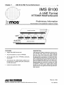
Chapter 2
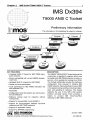
IMS Dx394 T9000 ANSI C Toolset
5
.<:<.
IMS Dx394
ii
i
i.
.ii
®R
U
•••••
•••••
•••••
/
T9000 ANSI C Toolset
i
i
i
.....<.•• ...........
Preliminary Information
The information in this datasheet is sUbject to change.
KEY FEATURES
• Complete ANSI C Toolset for IMS T9000 trans
puter networks
• Source compatible with current INMOS develop
ment tools
• Validated ANSI C compiler for IMS T9000
• Global and local optimization
• Code generation for IMS T9000 instruction set
and pipelined CPU
• Assembler
• Configuration tools that exploit new communica
tions architecture
• Software routing used for networks without
routing chips
DESCRIPTION
The INMOS T9000 ANSI C Toolset supports the
construction of parallel C programs which may
be loaded onto IMS T9000 networks via a link, or
put into a form suitable for booting from ROM.
The Toolset additionally includes the hardware
configuration tools required to initialize IMS
T9000 networks, fully supporting the use of IMS
C104 packet routing switches including initializ
ation and labelling of networks. The toolset
supports the use of the IMS C100 system
protocol converter device which provides a
means to connect IMS T2xx/T4xx/T8xx
networks to IMS T9000 networks.
• Support for mixing ANSI C and occam 2
• Support for communication between T2{T 4/T8
networks and IMS T9000 networks
• Support for assembler inserts
• Support for EPROM programming
m
':If,® SGS-1HOMSON
U\'lUD©OO@~[L~©lJOO@~D©~
INMOS is a member of the SGS-THOMSON Microelectronics Group
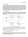
January 1993
42 159000
6
2.1 Introduction
Introduction
2.1
This document contains advance information for the INMOS T9000 ANSI C Toolset. Within this document
the current IMS T2xx, T4xx and T8xx transputers are called 'T2{T4{T8' transputers.
The INMOS T9000 ANSI C Toolset provides a complete ANSI C cross-development system for IMS
T9000 transputer network targets. It can be used to build sequential or parallel programs for single IMS
T9000 transputers or for multi-transputer IMS T9000 networks.
The Toolset supports the construction of parallel C programs, which may be loaded onto IMS T9000
networks via a link or put into a form suitable for booting from ROM. The Toolset also includes the hardware
configuration tools required to initialize IMS T9000 networks. It fully supports the use of IMS C1 04 packet
routing switches including labelling and initializing. The Toolset also supports the use of the IMS C100
system protocol converter device which provides a means to connect T2{T4{T8 networks to IMS T9000
networks.
2.1.1
Key features
•
Full ANSI C cross-compiler (X3.159-1989) for IMS T9000 target networks
•
Validated against Plum Hall validation suite
•
Code generation for IMS T9000 instruction set and pipelined CPU
•
Excellent compile time diagnostics
•
Global and local optimization
•
Support for parallelism
•
Assembler
•
Support for assembler inserts
•
Listings of where variables and functions reside in memory
•
Small runtime overhead
•
Separate compilation, using linker and librarian tools
•
Tools for creating and loading multi-processor programs
•
Exploitation of the new communications architecture by the configuration tools
•
Software routing of channels for networks without routing chips
•
Automatic makefile generator
•
Mixed language programming support
•
Tools to support preparation of programs for EPROM
•
Consistent tools across PC and Sun-4 hosts
•
Support for dynamically loading programs and functions
2.1.2
Overview
The IMS T9000 transputer range of devices will be supported by the following software products:
•
IMS Dx394 T9000 ANSI C Toolset
2 IMS Dx394 T9000 ANSI C Toolset
7
•
IMS Dx395 T9000 occam 2 Toolset
•
IMS Dx390 T9000 INQUEST development environment, containing debugging and profiling
tools
In addition there will be other software products supporting the loading, running and serving of programs
over specific host / IMS T9000 interface boards. This software will be supplied with the hardware.
The INMOS T9000 ANSI C Toolset is source compatible with INMOS T2{T4{T8 Toolset products. This
has been achieved by using similar compiler, libraries, linker, configurer and other tools. Code written for
a single IMS T4xx or IMS T8xx can be ported directly to an IMS T9000 for performance enhancement.
The IMS T9000 offers two important enhancements; the new communications architecture and the new
pipelined CPU. In order to take full advantage of these features, a new Toolset has been developed which
will function alongside the existing Dx394 T9000 ANSI C Toolset. It is envisaged that IMS T9000 users
will adopt one of the following options, which are all supported by the software:
•
Use only IMS T9000 family devices. Users of T2{T4{T8 networks can recompile existing
T2{T4{T8 code for a new IMS T9000 network.
•
Connect a T2{T4{T8 network to an IMS T9000 family network, using an IMS C100 system
protocol converter as a gateway between the networks.
•
Build an IMS T9000 network with T2{T4{T8 products as peripherals, using IMS C100 system
protocol converters as interfaces.
The configuration tools are the main area in which the difference between the IMS T9000 and the T2{T4{T8
range is apparent to the programmer. Configuration is the process of mapping a multi-process network
application to a transputer network. Tools are provided in the INMOS T9000 ANSI C Toolset, allowing
users to:
•
describe a hardware network made up of IMS T9000 and IMS C104 packet routing switch
devices
•
define values for the user-programmable attributes of the devices (such as the ~MS T9000's
programmable memory interface, and the IMS C104 packet routing switch's interval labelling
registers)
•
define how processes in the application should be mapped to processors in the network
The tools allow the full user-programmable functionality of the IMS T9000 and IMS C104 devices to be
used with simple textual descriptions of attribute values, without the need to write any low-level configura
tion code.
The configuration tools can check the network description to ensure that the network is properly
connected. Applications of arbitrary connectivity can be mapped onto the hardware network. Where the
network includes IMS C104 packet routing switches, the headers required to connect the channels
between processors are calculated automatically by the tools. If the network does not contain IMS C1 04
packet routing switches, the tools provide software through-routing so that channels may still be
connected between non-neighboring processors.
EPROM tools are provided to support the creation of initialization ROMs for IMS T9000 transputers, and
the creation of system ROMs containing application code.
The debugger supplied in INQUEST supports source-level and low-level debugging of multi-process and
multi-processor programs. The debugger runs on the host computer from which the IMS T9000 network
has been loaded. A graphical user interface, with multiple windows, simplifies use of this sophisticated
tool. INQUEST also includes profiling tools for detecting program 'hot-spots' and for evaluating how
effectively parallel programs use a network of processors.
2.1.3
Hosts
Programs developed using the Toolset are both source and binary compatible across all host development
machines. The INMOS T9000 ANSI C Toolset is available for the following development platforms:
2.2 IMS T9000 networks
8
IMS D4394 T9000 ANSI C Toolset for Sun-4 under SunOS 4.1.1
IMS D7394 T9000 ANSI C Toolset for IBM PC under MS-DOS 5
2.1.4
Comparison with IMS Dx314 Professional ANSI C Toolset
The INMOS T9000 ANSI C Toolset is fully compatible with the IMS Dx314 Professional ANSI C Toolset.
In particular:
•
they are source compatible,
•
the same libraries have been implemented to support parallelism,
•
the parallel library interface is the same,
•
the linker and librarian are functionally the same,
•
the configuration language is upwards compatible.
In addition some new features have been introduced, including:
2.2
•
a single compiler including all the optimizing features of the IMS Dx314 optimizing compiler
•
a number of IMS T9000-specific optimizations,
•
modified library code to better exploit the IMS T9000,
•
new configuration tools for software and hardware configuration which support the new IMS
T9000 communications architecture.
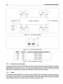
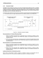
IMS T9000 networks
The new generation transputer, the IMS T9000, provides major enhancements to the communications
capabilities of transputer networks. The INMOS T9000 ANSI C Toolset provides support for these features
in the form of new configuration and initialization tools.
Using the IMS T9000 transputer and the INMOS T9000 ANSI C Toolset, a large network of processes
and channels may be programmed quite independently of the transputer network on which it will be
implemented. The IMS T9000 can multiplex a large number of channels, called virtual channels, onto a
single physical link. This allows a large network of channels between processes to be efficiently imple
mented on smalllMS T9000 networks without routing or multiplexing software.
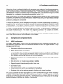
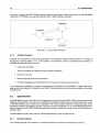
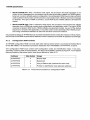
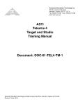
Control
link process
Control link network
Data
Data link network
link process
Host server
Controlling processor
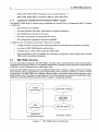
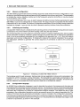
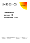
Figure 2.1
Transputer network
IMS T9000 network architecture
2 IMS Dx394 T9000 ANSI C Toolset
9
This hardware multiplexing support is complemented by a software through-routing mechanism provided
by the INMOS T9000 ANSI C Toolset. The combination of hardware multiplexing and software through
routing allow any user-defined channel connections to be specified and implemented with optimal flexi
bility.
The IMS C104 packet routing switch gives higher communications performance in larger systems. It is
a fast packet router which can route each incoming packet out along anyone of its links, depending on
the packet header added to the data by the sending transputer. It enables direct connections between the
transputers in a large network and can remove the need for software through-routing. Large networks may
also be implemented without packet routing switches, in which case each IMS T9000 may have a direct
connection to up to four other devices.
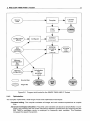
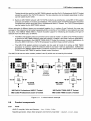
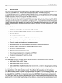
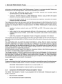
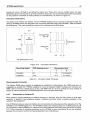
An IMS T9000 transputer system has a network of links for data communications plus a separate network
of control links for system initialization and debugging control. An IMS T9000 network can be viewed as
a number of processors each of which is connected to both the data network and the control network.
During system development, both networks should also be connected to the host or other controlling
processor, as shown in Figure 2.1.
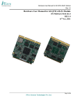
----------------1
1
~--------------~
~---------'
I
IMS
T9000
IMS
T9000
IMS
T9000
IMS
T9000
Host
....c- --~
...
~
1
Control link
I
Data link
Figure 2.2
2.2.1
1
---------------- --------1
1
1
IMS T9000 network example
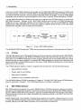
The IMS T9000 family of devices
The INMOS T9000 ANSI C Toolset supports the full family of the IMS T9000 transputer and associated
communications and interface chips - the IMS C104 packet routing switch and the IMS C100 system
protocol converter. The IMS C1 04 packet routing switch is a 32-way packet router. The IMS C1 00 system
protocol converter allows a T9000 data link and control link to be connected to T2/T4/T8 links and system
services. It provides a gateway to connect a T2/T4/T8 network to aiMS T9000 network.
2.3
Parallel programming
The INMOS T9000 ANSI C Toolset supports parallelism on individual transputers and parallelism across
networks of IMS T9000 transputers.
The transputer programming model consists of parallel processes communicating through channels.
Channels connect pairs of processes and allow data to be passed between them. Each process can itself
be built from a number of parallel sub-processes, so that an entire software system can be described as
2.3 Parallel programming
10
a process hierarchy. Processes may be created at high and low priority levels. Interrupt routines are
typically implemented as high priority processes. This model is consistent with many modern software
design methodologies.
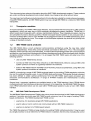
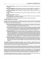
Figure 2.4 shows a collection of four processes communicating through channels. The mux process
communicates with a host computer and hands out work to be done to one of three worker processes.
Results from the workers are then returned to the host by the mux process. The following example shows
how this collection of processes can be described in C to run on a single IMS T9000 transputer. Section
2.6.4 shows how the parallel processes in the program can be mapped onto a network of processors using
the configuration language.
IMS C104
packet routing ~~Ni.
switch
•
IMS TaOS
IMS C100
system protocol
converter
IMS T9000
IMS T9000
Figure 2.3
IMS T9000 family of devices
hostout
hostin
wkrOut[3],
wkrln[3]
out
out
in
worker[O]
in
worker[1]
Figure 2.4
Software network
worker[2]
2 IMS Dx394 T9000 ANSI C Toolset
/*
Example program
11
*/
#include <process.h>
#include <misc~h>
#include <stdlib.h>
/*
Define prototypes for process functions
*/
void fmux (Process*, Channel*, Channel*, Channel*[], Channel*[], int);
/* process, hostin, hostout, in, out, no_workers */
void fwkr (Process*, Channel*, Channel*, int);
/* process, in, out, worker_id */
/*
Main program
*/
int main (int argc, char *argv[], char *envp[],
Channel *in[], int inlen, Channel *out[], int outlen)
int i;
/* Declare processes and channels */
Channel *hostin, *hostout, *wkrln[3], *wkrOut[3];
Process *mux, *worker[3];
/* Allocate channels */
hostin = in[l];
hostout = out[l];
for (i = 0; i < 3; ++i)
{
wkrln[i] = ChanAlloc ();
wkrOut[i] = ChanAlloc ();
/* Allocate processes */
mux = ProcAlloc (fmux, 0, 5, hostin ,hostout ,wkrln, wkrOut, 3);
for (i = 0; i < 3; ++i)
{
worker[i] = ProcAlloc (fwkr, 0, 3, wkrln[i], wkrOut[i], i);
}
/* Start the processes running in parallel */
ProcPar (mux, worker[O], worker[l], worker[2], NULL);
exit (0);
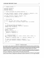
Figure 2.5
Parallel processes
By using library calls, parallel processes may be created dynamically. Processes may be created individu
ally in which case the function call will return immediately with the called process executing concurrently
with the calling process, or created as a group, in which case the function will return when all the processes
within the group have completed. Processes communicate by message passing over channels.
The example in Figure 2.5 illustrates how to program the collection of parallel processes shown diagram
matically in Figure 2.4. The functions fmux and fwkr contain the executable code of the processes mux
and worker respectively. These processes communicate using channels.
The ANSI C compiler in the Toolset can be used to compile the program shown in Figure 2.5. The compiled
code can then be linked, configured and collected to produce a code file to run on a single transputer.
2.4 Compiler and compilation tools
12
Alternatively it may be preferred to distribute the processes over a network of more than one processor,
in which case the code for the mux and worker processes would be compiled and linked separately. The
linker produces processes in the form of fully linked units. A network of fully linked processes can be
distributed over a network of processors using the configuration tools. The code shown in Figure 2.5 would
be replaced by a configuration description, as described in Section 2.6.4.
Each process has its own stack space (typically allocated from the heap of the main process) but the
processes in asingle linked unit share static space, heap space and code (including libraries). Processes
created in this way can communicate by message-passing over channels or by shared data (optionally
protected by semaphores or channels).
Functions are provided to read a message from one of a list of channels (implementing the occam ALT
construct), to time-out on channel input and to access the high and low resolution timers built into the IMS
T9000 transputer. The transputer's hardware scheduler provides extremely efficient scheduling of these
processes and efficiently implements many features which would normally require a real-time executive.
The ANSI C compiler operates from a host command line interface. The pre-processor is integrated into
the compiler for fast execution. The compile time diagnostics provided by the compiler are excellent.
These include type checking in expressions and type checking of function arguments.
The tools integrate into the host operating system build utilities, allowing, for example, the use of standard
editor, make and source code and configuration control utilities.
2.4
Compiler and compilation tools
2.4.1
ANSI C conformance
The INMOS T9000 ANSI C Toolset supports the full standard language as defined in X3.159-1989. The
key extensions and functions which are in the ANSI standard but not in the original definition of C by
~ernighan and Ritchie are:
•
Prototypes to define function parameters.
•
Better definition of the pre-processor.
•
Longer identifiers. The standard specifies at least 31 characters are significant in identifiers and
six characters for external names. The INMOS ANSI C Toolset implementation allows arbitrarily
long identifiers, the first 256 characters of which are significant.
•
Trigraphs introduced for use by some character sets which do not have some of the normal C
characters.
•
Data items which can be declared as const or volatile.
•
Support for special character sets (including Asian ones).
•
Enumeration types.
•
Implementation limits which are accessible from header files.
•
Structures which can be assigned, passed to functions and returned from them.
The compiler passes all the tests in the validation suite from Plum Hall. The compiler will be validated by
the British Standards Institution (BSI). The validation is recognized across Europe by the French
(AFNOR) and Italian (IMO) Standards Institutes. The standards authority in Japan (JMI) has also agreed
to harmonize their C validation with Europe. The USA National Institute of Standards and Technology
(NIST) is expected to recognize the validation in due course.
2 IMS Dx394 19000 ANSI C Toolset
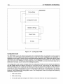
Source
code
13
Compiler
Librarian
ilibr
Linker
ilink
Configurer
Collector
NDL
network
description
ieprom
Memory
configuration
tool
imem
Initialization
file
generator
inif
Memory
configuration
~
Source files
Target file
Figure 2.6
2.4.2
Program build model for the INMOS T9000 ANSI C Toolset
Optimization
The compiler implements a wide range of local code optimization techniques.
Constant folding. The compiler evaluates all integer and real constant expressions at compile
time.
Advanced workspace allocation. Frequently used variables are placed at small offsets in work
space, thus reducing the size of the instructions needed to access them and ensuring that the
IMS T9000's workspace cache is employed for frequently used variables. This therefore
increases the speed of execution.
2.4 Compiler and compilation tools
14
Dead-code elimination. Code that cannot be reached during the execution of the program is
removed.
Peep-hole optimization. Code sequences are selected that are the fastest for the operation. For
example, single precision floating variables are moved using the integer move operations.
Instruction scheduling. Where possible the compiler exploits the internal concurrency of the
transputer.
Constant caching. Some constants have their load time reduced by placing them in a constant
table.
Unnecessary jumps are eliminated.
Switch statements. The compiler can generate a number of different code sequences tailored to
cover the dense ranges within the total range.
Special idioms that are better on transputers are chosen for some code sequences.
Globally optimized code generation
When global optimizations is selected, the compiler extends the types of optimizations it performs to global
techniques. These have typically given a 15%-25% improvement in speed over the local optimizations,
as measured by a suite of internal benchmarks.
Common sub-expression elimination removes the evaluation of an expression where it is known
that the value has already been computed; the value is stored in a temporary local workspace.
This improves the speed of a program and reduces code size.
Loop invariant code motion can move the position where an expression is evaluated from within
a loop to outside it. If the expression contains no variables that are changed during the execution
of a loop, then the expression can be evaluated just once before the loop is entered. By keeping
the result in a temporary location, the speed of execution of the whole loop is increased.
Tail-call optimization reduces the number of calls and returns executed by a program. If the last
operation of a function is to invoke another function and immediately return the value therefrom,
then the compiler attempts to re-use the same workspace area by just jumping to (rather than
calling) the lower level function. The called function then returns directly to where the upper level
function was called from. In the case where the call is a recursive call to the same function, then
the workspace is exactly the right size, and a saving is also made because the stack adjustment
instructions are no longer needed either. This optimization saves time and total stack space.
Workspace allocation by coloring reduces the amount of workspace required by using a word
for two variables when it can be determined that they are not both required at the same time. In
addition the variables that are most frequently used are placed at lower offsets in workspace.
This reduces the number of prefixes needed to access the variables and so reduces the total
code size.
The optimizing compiler also implements a pragma, IMS_nosideeffects, whereby the user can
indicate that a function does not have any side-effects on external or static variables. The optimizer can
then use this information to make assumptions about what state can be changed by a function invocation
and hence about the validity of any previously computed expressions.
To make the access to some of the transputer's instructions even more effective, a number of special
library functions have been defined which the optimizing compiler can render as in-line code. This removes
the overhead of a library call, but it also gives the optimizer more information on what the program is doing.
Normally, when the optimizer sees a function containing some assembler code, it must make very
conservative assumptions about the effect the code has on its surroundings, e.g. on static variables and
parameters. By using the functions defined to access the instructions, the optimizer knows exactly what
the effects will be and can make the minimally correct assumptions for the side-effects of the code.
The transputer instructions that can be accessed in this way include block moves, channel input and
output, bit manipulation, CRC computations and some scheduling operations.
2 IMS Dx394 T9000 ANSI C Toolset
15
Use of IMS T9000 features
2.4.3
Programs are compiled to run as L-processes (with a local trap handler) on the IMS T9000. A trap handler
is set up to catch and handle program runtime errors. Signal handlers can be set up to handle certain
run-time errors.
The code generated by the compiler, and in the supporting libraries, makes full use of the new features
introduced to the transputer instruction set in the IMS T9000. In particular:
•
The part-word support instructions are used to improve the handling of a-bit and 16-bit integers.
•
The new floating point instructions, fpsqrt and fprem are used.
•
volatile variables are implemented using the device access instructions.
•
The semaphore support in the runtime library is implemented using the new semaphore instruc
tions.
•
Care has been taken in the code generation and optimization to ensure that effective use is made
of the IMS T9000's workspace cache and CPU pipeline.
Access to the full IMS T9000 instruction set is available through assembly inserts.
2.4.4
TCOFF
The binary code produced by INMOS T9000 ANSI C Toolset tools is in Transputer Common Object File
Format (TCOFF). This allows integration with other TCOFF-based utilities, including the INMOS T9000
occam 2 Toolset and the INQUEST development environment.
2.4.5
Separate compilation
Collections of subprograms can be compiled separately using the INMOS ANSI C compiler and optionally
combined into a library. The Iinker is used to combine separately compiled functions and procedures as
a linked unit. A single copy of a linked unit cannot be distributed over more than one processor. The linker
supports selective loading of library units.
2.4.6
Mixed language programming
The INMOS T9000 ANSI C and occam 2 compilers are fully compatible and allow simple mixing of
languages. occam and C processes may be freely mixed when configuring a program for a single
transputer or a network of transputers. Such processes will run in parallel and communicate using
channels.
The INMOS T9000 ANSI C Toolset allows occam 2 procedures and single-valued occam 2 functions
to be called from C just like other C functions. Pragmas are provided to tell the C compiler not to generate
the hidden static link parameter (Which is required by C but not by OCCam) and to change the external
names of procedures and function, since occam names may not be legal C function names.
Similarly, the INMOS T9000 occam 2 Toolset supports calling C functions directly from
functions which require access to static variables are supported.
2.4.7
occam. C
Assembler code
The INMOS T9000 ANSI C Toolset provides a very powerful assembler insert facility. Assembler code
can be written at any point in the source code to achieve direct access to transputer instructions for
reasons of speed or code size. Full access is available to the IMS T9000 transputer instruction set and
C program variables.
2.5 Libraries
16
The assembler insert facility supports:
•
Access to the full instruction set of the IMS T9000 transputer
•
Symbolic access to automatic and static variables
•
Pseudo-operations to load multi-word values into registers
•
Loading results of expressions to registers using the pseudo-operations.
•
Labels and jumps
•
Directives for instruction sizing, stack access, return address access etc.
•
The INMOS ANSI C pre-processor may be used to provide macro assembly programming facili
ties.
If there is no other way to obtain the code required, for example when writing customized bootstrap
mechanisms, then the final stage of the compiler may be invoked as an assembler to assemble user
written assembler code.
2.5
Libraries
The full set of ANSI C libraries is provided.
The standard mathematics library operates in double precision. Versions of the mathematical functions
are provided that operate on float arguments and return float values. These libraries provide improved
performance for applications where performance requirements override accuracy requirements.
The standard C mathematical functions provided use the same code as the occam libraries. This
ensures identical results and accuracy for all compilers supported by INMOS. A reduced C library is
supplied to minimize code size for embedded systems applications and for processes which do not need
to access host operating system facilities.
Extra libraries are provided to support parallel programming and to provide access to the special features
of the transputer. Functions are provided to create parallel processes dynamically. Processes may be
created individually in which case the function call will return immediately with the called process executing
concurrently with the calling process, or created as a group, in which case the function will return when
all the processes within the group have completed.
Functions are provided to support communications between processes by message passing over chan
nels. Any form of data may be sent or received on a single channel. Input from a list of channels is also
supported. Library functions provide access to the high and low resolution timers built into the transputer,
allowing any process to read the current timer value or delay for a specified time. Channel inputs may also
be timed out. Support is also provided for semaphores.
Support is given for loading code dynamically. Miscellaneous library functions are also provided, including
functions to identify the type of host, the host link and the boot link.
2.6
Configuration, initialization and loading
Configuration is the process of defining how an application program is to be run on the available hardware.
Given a description of the hardware network, the software network of an application and the mapping
between them, the INMOS T9000 ANSI C Toolset produces a bootable file which can be sent to the
network for execution. The hardware network description is also used to prepare a network initialization
file which is used to initialize the network and bootstrap the processors into a state where they are ready
to receive the bootable file.
A configuration description file is used as input to a tool known as the configurer. The description is written
in a C-Iike language which is upwards compatible with the configuration language in the Dx314 Profes
2 IMS Dx394 T9000 ANSI C Toolset
17
sional ANSI C Toolset. The configuration description describes the application as a network of processes
and channels. It indicates which linked files should be used as the code for each process, and it also
indicates on which processor each process is to be run.
The hardware description is separate from the rest of the configuration description. It is written in the
INMOS Network Description Language (NDL). The configuration description refers to the NDL description
of the hardware by means of a #network directive. The hardware description describes the processors
and routing devices in the network and their connections.
The main features of the configuration tools are as follows:
2.6.1
•
To initialize, boot and load an IMS T9000 network, it is not necessary to write any low-level code;
instead the attributes of devices are specified by simple textual statements in the network
description, and the low level code is generated automatically by the tools.
•
The network description for a particular network can be written once, when the hardware is
designed, and does not normally need to be changed between different applications.
•
The configuration tools will check the correctness of the network description; this includes
checking the labelling of the routing chips for deadlock freedom.
•
Channels specified by the user in the configuration description are automatically mapped by the
tools. In a system with routing devices, the configuration tools calculate the routing headers
required forthe user's channels. If there are no routing devices in the system, the configurer adds
any software through-routing mechanisms required. Thus the software network is not
constrained by the topology of the hardware network.
•
For a particular application, the tools can produce either a bootable file which can be used to load
the network from a host, or a boot-from-ROM file which can be used to program a ROM on one
of the processors in the network.
•
Initialization of individuallM8 T9000 devices in the network (for example, setting up the external
memory interface) can be done over the control link, or from an initialization ROM local to each
IMS T9000. Support for generation of local initialization RaMs is included.
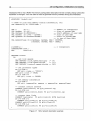
Network description
The Network Description Language (NDL) is used to describe the available hardware - the types of
processors, their attributes and how they are connected. Processor attributes include, for example, a
description of its memory map and its link speeds. The NDL also describes any packet routing switch
devices in the network and their attributes. Attributes of a routing device include the labelling of the routing
device, which indicates how packets from processors should be routed through it.
The network description will not normally change unless the hardware is changed. This NDL description
of the system is used by the tools for a variety of purposes, from initializing the hardware to mapping
application code onto processors. These tools can either read and check the NDL source directly or read
a binary version produced by the NDL compiler, indl.
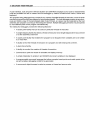
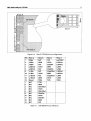
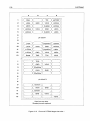
Figure 2.7 shows the NDL network description for the example network shown in Figure 2.10.
2.6.2
Memory configuration
The IMS T9000 programmable memory interface supports a wide variety of memory configurations. It can
be set up to provide the appropriate signals and timing needed by the memory being used. The parameters
to initialize the memory interface may be sent to the transputer using the control link or may be included
in the bootstrap code in ROM.
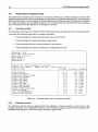
The memory configuration tool, imem, is used to assess and define memory interface parameters for each
IMS T9000. It can be run interactively or in batch mode. The output may be incorporated into the network
2.6 Configuration, initialization and loading
18
initialization file or into a ROM. The memory configuration description will not normally change unless the
hardware is changed. imem can also be used to generate memory interface timing documentation.
#INCLUDE "stdndl.inc"
-- Name of file with memory timing information, etc.
VAL memconfig IS "T9000.mem" :
VAL
VAL
VAL
VAL
VAL
n
SysMem
UsrBase
UsrMem
SysBase
IS
IS
IS
IS
IS
4 :
4*K
#80000000
(2*M) - SysMem
UsrBase+UsrMem
Number of transputers
Size of system RAM
Start address of user RAM
Size of user RAM
Start of system RAM
(= top of user RAM)
VAL memoryflags IS [[SysBase, SysMem, RAM + SYSTEM],
[UsrBase, UsrMem, RAM + USER]] :
-
[n]NODE p :
CONTROLPORT host :
ARC
hostlink
NETWORK fourT9
DO
-- set link
SET DEFAULT
SET DEFAULT
SET DEFAULT
n transputers
speeds
(link.speed.multiply := 10)
(link.speed.divide
:= [1])
(control.speed.divide := [8])
-- set processor types
DO i=O FOR n
SET p[i] (type := "T9000")
SET prO] (root := TRUE)
DO i=I FOR n-I
SET p[i] (root := FALSE)
-- set memory information
DO i=O FOR n
SET p[i] (memconfig, memory
memconfig, memoryflags)
-- connect control network
CONNECT host[control] TO p[O] [control.up]
DO i=O FOR n-I
CONNECT p[i] [control.down] TO p[i+I] [control.up]
connect data links
CONNECT host[data] TO p[O][link][O] WITH hostlink
DO i=O FOR n-I
CONNECT p[i][link][I] TO p[i+I][link][2]
CONNECT p[n-I][link][I] TO p[0][link][2]
DO i=O FOR n-2
CONNECT p[i][link][3] TO p[i+2][link][0]
Figure 2.7
NDL network description example
2 IMS Dx394 T9000 ANSI C Toolset
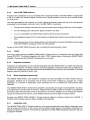
2.6.3
19
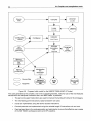
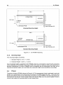
Initializing and loading
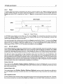
A hosted IMS T9000 network is initialized by first sending control commands to the transputers and routers
connected to the control network and then loading code using the data network.
The correct sequence of control network commands is held in a network initialization file, which contains
all the information needed to initialize a system through the control links prior to loading the application
code. It can be automatically generated by the initialization file generator tool, inif, from the network
description and memory configurations. To initialize the network, the network initialization file is used by
the initialization software to generate the correct sequence of commands to send to the control link
network.
The bootstrap code for each processor, loading code and user application code are all incorporated in the
bootable file with the necessary routing information. The bootable file is generated automatically by the
collector, icollect, from the configuration information and linked application code files. To load the code
onto the network, the bootable file is sent down the data link to the data link network.
Network
initialization
file
Bootable
file
Control link network
Data link network
Transputer network
Figure 2.8
2.6.4
Initializing a hosted IMS T9000 network
Configuration language
A C-like configuration language is used to describe the network of processes and channels and the
mapping of the processes onto the transputer network. The transputer network is described separately
in the network description file. Multiple processes may be mapped onto the same transputer. The network
description file is referred to by means of a #network configurer directive. This allows the user to map
processes in the configuration description onto the processors named in the network description file. The
routing of channels may be generated automatically or may be included in the configuration description.
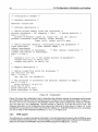
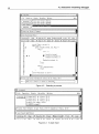
The following example illustrates just how easy it is to configure a program for transputers. Instead of using
the top level single transputer code shown in Figure 2.5, it may be preferred to distribute the program over
a network of processors, as shown in this example.
2.6 Configuration, initialization and loading
20
/* Configuration example */
/* Hardware description */
#network "fourT9.ndl"
/* Software description */
/* Define process memory sizes and interfaces */
process (stacksize = 2K, heapsize = 16k);
/* Define defaults */
rep i = 0 for 3
process (interface (input in, output out, int id)) wkr[i];
process (interface (input hostin, output hostout,
input in[3], output out[3])) mux;
/* Define external channels, interconnections and parameters */
input hostinput;
/* Host channel edges */
output hostoutput;
connect mux.hostin to hostinput;
/* Host channel connections */
connect mux.hostout to hostoutput;
rep i = 0 for 3
{
worker[i] (id = i); /* Set worker process id parameter*/
connect mux.in[i] to wkr[i].out;
connect mux.out[i] to wkr[i].in;
/* Mapping description */
/* Define linked file units for processes */
use "mux.lku" for mux;
rep i = 0 for 3
use "wkr.lku" for worker[i];
/* Map processes to processors and external channels to edges */
rep i = 0 for 3
place worker[i] on p[i+l];
place mux on p[O];
place hostinput on host;
place hostoutput on host;
Figure 2.9
Configuration
Figure 2.9 shows the configuration text for describing the software network of processes and channels
and mapping the software onto the hardware shown in Figure 2.10 and described in NDL in Figure 2.7.
The mux and worker processes in the software network have been compiled and linked into the files
mux .lku and wkr .lku respectively. The NDL shown in Figure 2.7 is in the file fourT9. ndl. The
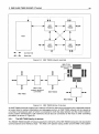
software description in the configuration text replaces the top level of code shown in Figure 2.5. In this
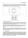
example the mux process runs on the root transputer, called p [ 0 ] , while the individual worker processes
run one on each of the transputers labelled p [ 1] to p [ 3] in Figure 2.10.
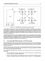
2.6.5
ROM support
The software can usually be developed and tested in a hosted development system without ROM by using
host files loaded via transputer links. As a final stage, the completed application software and initialization
data can be loaded into EPROMs using the EPROM program formatting tool, ieprom.
2 IMS Dx394 T9000 ANSI C Toolset
21
I
I
I
I
c1inkO
0
clink1
clink1
c1inkO
IMS
T9000
prO]
2
IMS
T9000
p[1]
0
Host
2
3
IMS
T9000
p[3]
clinkO
2
IMS
T9000
p[2]
c1ink1
Control link
3
clinkO
________ J
Data link
Figure 2.10
IMS T9000 network example showing link numbers
The EPROM formatting tool can produce a file suitable for programming a ROM; this may be either a
system ROM or a local ROM. A system ROM holds network initialization data and application software
for initializing and loading onto a network of transputers. Stand-alone systems will need to boot from a
system ROM. A local ROM holds local initialization data for only one transputer in a network. One or more
transputers in a network may be initialized from local RaMs, whether the application is loaded from a host
file or from a system ROM.
The EPROM formatting tool may read the network description, memory configurations and the collected
application software. From this data, the EPROM formatting tool can build a ROM file incorporating the
network initialization data and application software. A control file allows the user to control how the data
is arranged in the ROM. The ROM file may be produced in ASCII hexadecimal, Intel hexadecimal,
extended Intel hexadecimal, Motorola S-record or binary format.
2.7
Connecting IMS T9000 networks to T2/T4/T8 networks
IMS T9000 transputers have improved physical links and data protocols from the T2fT4fT8 family of
devices. In addition the method of initializing and controlling networks of devices is enhanced; IMS T9000
networks have a network of control links which is used to control (reset, bootstrap, monitor and analyze)
devices in the network.
The IMS C100 is a protocol converter chip for connecting IMS T9000 and T2fT4fT8 networks together,
and for converting the data communication and control interfaces. For detailed information on the IMS
C100, please consult the appropriate data sheet.
It is envisaged that IMS T9000 users will adopt one of the following options, which are all supported by
the software:
Use only T9000 family devices. Existing users of T2fT4fT8 networks can recompile existing
T2fT4fT8 code onto a new IMS T9000 network.
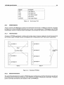
2 Connect a T2fT4fT8 network to an T9000 family network, using an IMS C1 00 system protocol
converter as a gateway between the networks, as shown in Figure 2.11. The T9000 ANSI C
2.8 Product components
22
Toolset should be used for the IMS T9000 network and the Dx314 Professional ANSI C Toolset
should be used for the T2/T4/T8 network. The two networks can be loaded separately or either
can be loaded by the other.
3 Build an IMS T9000 network with T2/T4/T8 products as peripherals, using IMS C100 system
protocol converters (in mode 2) as interfaces. The code for each T2/T4/T8 transputer should be
compiled and linked using the Dx314 Professional ANSI C Toolset. The T2/T4/T8 transputers
can be loaded by the IMS T9000 network.
When networks of different types are connected together (Le. in options 2 and 3 above), the user can
arrange for the networks to be loaded separately (from a host file or from ROM) or one network can load
the other. The INMOS T9000 ANSI C Toolset includes support for initializing and loading one type of
network from the other type, as follows:
•
The IMS C1 00 system protocol converter can be used (in mode 1) to allow a T2/T4/T8 processor
to control an IMS T9000 network (reset the network, initialize it and load it with an application).
Software is provided in the INMOS T9000 ANSI C Toolset for inclusion in users' applications, to
drive the IMS C100 from a T2/T4/T8 processor to perform these control functions.
•
The IMS C100 system protocol converter can be used (in mode 2) to allow an IMS T9000
processor to control a T2/T4/T8 network (reset it and load it with an application). Software is
provided in the INMOS T9000 ANSI C Toolset for inclusion in users' applications, to drive the IMS
C100 from an IMS T9000 to perform these control functions.
The IMS C1 00 has two other modes (modes 0 and 3) which are not used by this toolset.
IMS
T805
IMS
T9000
system
protocol
converter
IMS T9000
network
T2/T4/T8
network
IMS Dx314 Professional ANSI C Toolset
IMS Dx394 T9000 ANSI C Toolset
IMS Dx305 Professional occam 2 Toolset
IMS Dx395 T9000 occam 2 Toolset
Figure 2.11
2.8
2.8.1
A mixed network example
Product components
Tools
ANSI C compiler, linker and librarian - icc, ilink, ilibr
Makefile generator, binary lister program and memory map Iister - imakef, ilist, imap
2 IMS Dx394 T9000 ANSI C Toolset
Configuration tools - indl, imem, inif, icconf, icollect
EPROM programming tool - ieprom
2.8.2
Libraries
Full ANSI library plus parallel support - libc . lib
Reduced library for embedded systems - libcred. lib
Mixed language support library - centry. lib
Configuration support libraries
2.8.3
Sources
Programming examples
Makefile generator source files
Configuration support library source files
Network description examples
C start-up source files
Network control software source files
2.8.4
Documentation
Toolset User Guide
Tools Reference Manual
Language and Libraries Reference Manual
System Configuration Guide
Delivery Manual
ANSI C Toolset Handbook
2.9
Product variants
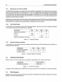
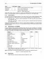
2.9.1
Sun-4 product
Product
•
IMS 04394 T9000 ANSI C Toolset
Operating requirements
For Sun-4 hosted cross-development the following will be required:
•
A Sun-4 workstation or server
•
SunOS 4.1.1 or later
•
10 Mbytes of free disk space.
For loading target systems, a suitable transputer network interface will be required.
Distribution media
Sun-4 software is distributed on DC600A data cartridges 60 Mbytes, QIC-24, tar format.
23
2.10 Problem reporting and field support
24
Licensing
The IMS 04394 T9000 ANSI C Toolset is a four-user product. For each product purchased, up to four
users are able to use the Toolset concurrently at anyone customer site. The tools can be run on any Sun-4
machine that is part of a network connected to a single machine where the licence manager is installed.
Further information about the licence manager is included in the product Delivery Manual. Multiple copies
can be purchased for larger project teams using volume discount curves.
No licence fee is charged for including INMOS libraries in customer products when linked with customer
applications using the INMOS linker, ilink. Example programs and other sources provided may be
included in software products, but INMOS Limited retain original copyright. Full licensing details are
available from SGS-THOMSON Sales Offices, Regional Technology Centers and authorized distributors.
2.9.2
IBM product
Product
•
IMS 07394 T9000 ANSI C Toolset
Operating requirements
For PC hosted cross-development one of the following will be required:
•
IBM PC with a 386 or 486 processor and a minimum of 4 Mbytes memory
In each case the following will be required:
•
DOS 5.0 or later
•
9 Mbytes of free disk space
For loading target systems, a suitable transputer network interface will be required.
Distribution media
Software is distributed on two media systems, both of which are supplied in the product:
•
1.2 Mbytes (96TPI) 5.25 inch IBM format floppy disks
•
1.44 Mbytes 3.5 inch IBM format floppy disks.
Licensing
The IMS 07394 T9000 ANSI C Toolset is a single-user product. Multiple copies can be purchased for
larger project teams using volume discount curves.
No licence fee is charged for including INMOS libraries in customer products when linked with customer
applications using the INMOS linker, ilink. Example programs and other sources provided may be
included in software products, but INMOS Limited retain original copyright. Full licensing details are
available from SGS-THOMSON Sales Offices, Regional Technology Centers and authorized distributors.
2.10
Problem reporting and field support
A registration form is provided with each product. Return of the registration form will ensure you are eligible
for future product updates. Software problem report forms are included with the software. INMOS prod
ucts are supported worldwide through SGS-THOMSON Sales Offices, Regional Technology Centers and
authorized distributors.
Chapter 3
IMS Dx395 T9000 occam 2 Toolset
25
IMS Dx395
®
T9000 occam 2 Toolset
Preliminary Information
The information in this datasheet is subject to change.
KEY FEATURES
• Complete occam 2 toolset for IMS T9000 trans
puter networks
• Source compatible with current INMOS develop
ment tools
• Code generation for IMS T9000 instruction set
and pipelined CPU
• Configuration tools that exploit new communica
tions architecture
• Software routing used for networks without
routing chips
• Support for mixing ANSI C and occam 2
• Support for communication between T2/T4/T8
networks and IMS T9000 networks
• Support for assembler inserts
DESCRIPTION
The INMOS T9000 occam 2 Toolset supports
the construction of occam 2 programs which
may be loaded onto IMS T9000 networks via a
link, or put into a form suitable for booting from
ROM. The Toolset additionally includes the
hardware configuration tools required to
initialize IMS T9000 networks, fully supporting
the use of IMS C104 packet routing switches
including initialization and labelling of networks.
The toolset supports the use of the IMS C100
system protocol converter device which
provides
a
means
to
connect
IMS
T2xx/T4xx/T8xx networks to IMS T9000
networks.
• Support for EPROM programming
1':=-= SGS-1HOMSON
...,I®
[i\/;\]D©rn3@~[]J~©l]'rn3@~D©~
INMOS is a member of the SGS-THOMSON Microelectronics Group
January 1993
42 158900
3.1 Introduction
26
Introduction
3.1
This document contains advance information for the INMOS T9000 occam 2 Toolset. Within this docu
ment the current IMS T2xx, T4xx and T8xx transputers are called 'T2/T4/T8' transputers.
The INMOS T9000 occam 2 Toolset provides a complete occam 2 cross-development system for IMS
T9000 transputer network targets. It can be used to build sequential or parallel programs for single IMS
T9000 transputers or for multi-transputer IMS T9000 networks.
The Toolset supports the construction of occam 2 programs, which may be loaded onto IMS T9000
networks via a link or put into a form suitable for booting from ROM. The Toolset also includes the hardware
configuration tools required to initialize IMS T9000 networks. It fully supports the use of IMS C1 04 packet
routing switches including labelling and initializing. The Toolset also supports the use of the IMS C100
system protocol converter device which provides a means to connect T2/T4/T8 networks to IMS T9000
networks.
3.1.1
Key features
• occam 2 cross-compiler for IMS T9000 target networks
•
Code generation for IMS T9000 instruction set and pipelined CPU
•
Scientific libraries
•
Support for assembler inserts
•
Listings of where variables and functions reside in memory
•
Separate compilation, using linker and librarian tools
•
Tools for creating and loading multi-processor programs
•
Exploitation of the new communications architecture by the configuration tools
•
Software routing of channels for networks without routing chips
•
Automatic makefile generator
•
Mixed language programming support
•
Tools to support preparation of programs for EPROM
•
Consistent tools across PC and Sun-4 hosts
3.1.2
Overview
The IMS T9000 transputer range of devices will be supported by the following software products:
•
IMS Dx394 T9000 ANSI C Toolset
•
IMS Dx395 T9000
•
IMS Dx390 T9000 INQUEST development environment, containing debugging and profiling
tools
occam 2 Toolset
In addition there will be other software products supporting the loading, running and serving of programs
over specific host / IMS T9000 interface boards. This software will be supplied with the hardware.
The INMOS T9000 occam 2 Toolset is source compatible with INMOS T2/T4/T8 Toolset products. This
has been achieved by using similar compiler, libraries, linker, configurer and other tools. Code written for
a single IMS T4xx or IMS T8xx can be ported directly to an IMS T9000 for performance enhancement.
The IMS T9000 offers two important enhancements; the new communications architecture and the new
pipelined CPU. In order to take full advantage of these features, a new Toolset has been developed which
3 IMS Dx395 T9000
occam 2 Toolset
27
will function alongside the existing Dx395 T9000 occam 2 Toolset. It is envisaged that IMS T9000 users
will adopt one of the following options, which are all supported by the software:
•
Use only IMS T9000 family devices. Users of T2fT4fT8 networks can recompile existing
T2fT4fT8 code for a new IMS T9000 network.
•
Connect a T2fT4fT8 network to an IMS T9000 family network, using an IMS C100 system
protocol converter as a gateway between the networks.
•
Build an IMS T9000 network with T2fT4fT8 products as peripherals, using IMS C100 system
protocol converters as interfaces.
The configuration tools are the main area in which the difference between the IMS T9000 and the T2fT4fT 8
range is apparent to the programmer. Configuration is the process of mapping a multi-process network
application to a transputer network. Tools are provided in the INMOS T9000 occam 2 Toolset, allowing
users to:
•
describe a hardware network made up of IMS T9000 and IMS C104 packet routing switch
devices
•
define values for the user-programmable attributes of the devices (such as the IMS T9000's
programmable memory interface, and the IMS C104 packet routing switch's interval labelling
registers)
•
define how processes in the application should be mapped to processors in the network
The tools allow the full user-programmable functionality of the IMS T9000 and IMS C104 devices to be
used with simple textual descriptions of attribute values, without the need to write any low-level configura
tion code.
The configuration tools can check the network description to ensure that the network is properly
connected. Applications of arbitrary connectivity can be mapped onto the hardware network. Where the
network includes IMS C104 packet routing switches, the headers required to connect the channels
between processors are calculated automatically by the tools. If the network does not contain IMS C1 04
packet routing switches, the tools provide software through-routing so that channels may still be
connected between non-neighboring processors.
EPROM tools are provided to support the creation of initialization ROMs for IMS T9000 transputers, and
the creation of system ROMs containing application code.
The debugger supplied in INQUEST supports source-level and low-level debugging of multi-process and
multi-processor programs. The debugger runs on the host computer from which the IMS T9000 network
has been loaded. A graphical user interface, with multiple windows, simplifies use of this sophisticated
tool. INQUEST also includes profiling tools for detecting program 'hot-spots' and for evaluating how effec
tively parallel programs use a network of processors.
3.1.3
Hosts
Programs developed using the Toolset are both source and binary compatible across all host development
machines. The INMOS T9000 occam 2 Toolset is available for the following development platforms:
IMS D4395 T9000 occam 2 Toolset for Sun-4 under SunOS 4.1.1
IMS D7395 T9000 occam 2 Toolset for IBM PC under MS-DOS 5
3.1.4
Comparison with IMS Dx305 Professional
occam 2 Toolset
The INMOS T9000 occam 2 Toolset is fully compatible with the IMS Dx305 Professional occam 2
Toolset. In particular:
•
they are source compatible,
•
the same libraries have been implemented,
3.2 IMS T9000 networks
28
•
the library interface is the same,
•
the linker and librarian are functionally the same,
•
the configuration language is upwards compatible.
In addition some new features have been introduced, including:
•
3.2
a number of IMS T9000-specific optimizations,
•
modified library code to better exploit the IMS T9000,
•
new configuration tools for software and hardware configuration which support the new IMS
T9000 communications architecture.
IMS T9000 networks
The new generation transputer, the IMS T9000, provides major enhancements to the communications
capabilities of transputer networks. The INMOS T9000 occam 2 Toolset provides support for these
features in the form of new configuration and initialization tools.
Using the IMS T9000 transputer and the INMOS T9000 occam 2 Toolset, a large network of processes
and channels may be programmed quite independently of the transputer network on which it will be imple
mented. The IMS T9000 can multiplex a large number of channels, called virtual channels, onto a single
physical link. This allows a large network of channels between processes to be efficiently implemented
on small IMS T9000 networks without routing or multiplexing software.
This hardware multiplexing support is complemented by a software through-routing mechanism provided
by the INMOS T9000 occam 2 Toolset. The combination of hardware multiplexing and software through
routing allow any user-defined channel connections to be specified and implemented with optimal flexi
bility.
The IMS C104 packet routing switch gives higher communications performance in larger systems. It is
a fast packet router which can route each incoming packet out along anyone of its links, depending on
the packet header added to the data by the sending transputer. It enables direct connections between the
transputers in a large network and can remove the need for software through-routing. Large networks may
also be implemented without packet routing switches, in which case each IMS T9000 may have a direct
connection to up to four other devices.
Control
link process
Control link network
Data
Data link network
link process
Host server
Controlling processor
Figure 3.1
Transputer network
IMS T9000 network architecture
3 IMS Dx395 T9000
occam 2 Toolset
29
IMS
T9000
IMS
T9000
IMS
T9000
IMS
T9000
Host
--c- - -~
I
Control link
I
----------------
I
I
--------I
Data link
Figure 3.2
IMS T9000 network example
IMS C100
system protocol
converter
IMS T9000
IMS Ta05
IMS T9000
Figure 3.3
IMS T9000 family of devices
An IMS T9000 transputer system has a network of links for data communications plus a separate network
of control links for system initialization and debugging control. An IMS T9000 network can be viewed as
a number of processors each of which is connected to both the data network and the control network.
During system development, both networks should also be connected to the host or other controlling
processor, as shown in Figure 2.1.
3.2.1
The IMS T9000 family of devices
The INMOS T9000 occam 2 Toolset supports the full family of the IMS T9000 transputer and associated
communications and interface chips - the IMS C104 packet routing switch and the IMS C100 system
3.3 Parallel programming
30
protocol converter. The IMS C1 04 packet routing switch is a 32-way packet router. The IMS C1 00 system
protocol converter allows a T9000 data link and control link to be connected to T2/T4/T8Iinks and system
services. It provides a gateway to connect a T2/T4/T8 network to aiMS T9000 network.
3.3
Parallel programming
The INMOS T9000 occam 2 Toolset supports parallelism on individual transputers and parallelism
across networks of IMS T9000 transputers.
The transputer programming model consists of parallel processes communicating through channels.
Channels connect pairs of processes and allow data to be passed between them. Each process can itself
be built from a number of parallel sub-processes, so that an entire software system can be described as
a process hierarchy. Processes may be created at high and low priority levels. Interrupt routines are typi
cally implemented as high priority processes. This model is consistent with many modern software design
methodologies.
occam 2 is an efficient and effective language for parallel programming. It is a high level, structured
language, providing simple constructs for creating parallel processes and for message-passing using
channels. Each channel has a PROTOCOL which determines the types of messages that may flow along
it. The occam compiler provides comprehensive compile and run-time checking which considerably
reduces the number of coding and usage errors.
Figure 2.4 shows a collection of four processes communicating through channels. The mux process
communicates with a host computer and hands out work to be done to one of three worker processes.
Results from the workers are then returned to the host by the mux-process. The following example shows
how this collection of processes can be described in occam to run on a single IMS T9000 transputer.
Section 2.6.4 shows how the parallel processes in the program can be mapped onto a network of proces
sors using the configuration language.
hostout
hostin
wkrOut[3] ,
wkrln[3]
out
out
in
worker[O]
in
worker[1]
Figure 3.4
worker[2]
Software network
The example in Figure 2.5 illustrates how to program the collection of parallel processes shown diagram
matically in Figure 2.4. The files mux. teo and worker. teo contain the executable code of the
processes mux and worker respectively. These processes communicate using channels.
The occam 2 compiler in the Toolset can be used to compile the program shown in Figure 2.5. The
compiled code can then be linked, configured and collected to produce a code file to run on a single trans
puter. Alternatively it may be preferred to distribute the processes over a network of more than one
processor, in which case the code for the mux and worker processes would be compiled and linked sepa
rately. The linker produces processes in the form of fully linked units. A network of fully linked processes
3 IMS Dx395 T9000
occam 2 Toolset
31
can be distributed over a network of processors using the configuration tools. The code shown in
Figure 2.5 would be replaced by a configuration description, as described in Section 2.6.4.
#INCLUDE "hostio.inc" #USE "mux.tco"
#USE "worker.tco"
contains SP protocol definition
PROC example (CHAN OF SP hostinput, hostoutput,
[3]CHAN OF SP wkrIn, wkrOut:
PAR
mux(hostinput, hostoutput, wkrOut, wkrIn)
PAR i = 0 FOR 3
worker(wkrIn[i], wkrOut[i])
Figure 3.5
[]INT memory)
Parallel processes
occam constructs are provided to read a message from one of a list of channels, to time-out on channel
input and to access the high and low resolution timers built into the IMS T9000 transputer. The transputer's
hardware scheduler provides extremely efficient scheduling of these processes and efficiently implements
many features which would normally require a real-time executive.
The tools integrate into the host operating system build utilities, allOWing, for example, the use of standard
editor, make and source code and configuration control utilities.
3.4
Compiler and compilation tools
3.4.1
Optimization
The compiler implements a wide range of code optimization techniques.
Constant folding. The compiler evaluates all constant expressions at compile time.
Advanced workspace allocation. Frequently used variables are placed at small offsets in work
space, thus reducing the size of the instructions needed to access them and ensuring that the
IMS T9000's workspace cache is employed for frequently used variables. This therefore
increases the speed of execution.
Dead-code elimination. Code that cannot be reached during the execution of the program is
removed.
Peep-hole optimization. Code sequences are selected that are the fastest for the operation.
Instruction scheduling. Where possible the compiler exploits the internal concurrency of the
transputer.
Constant caching. Some constants have their load time reduced by placing them in a constant
table.
Special idioms that are better on transputers are chosen for some code sequences.
In-line code Procedures and functions can optionally be implemented as in-line code.
The compiler and linker provide features which allow programmers to make good use of the IMS T9000
transputer's internal memory when used as on-chip RAM.
3.4.2
Use of IMS T9000 features
Programs are compiled to run as L-processes (with a local trap handler) on the IMS T9000. A trap handler
is set up to catch and handle program runtime errors. The behavior of the program after an error (HALT
or STOP) is determined by the trap handler installed rather than at compilation time.
3.4 Compiler and compilation tools
32
Source
code
Librarian
ilibr
Compiler
Linker
ilink
Configurer
Collector
icollect
EPROM
formatting
tool
ieprom
Memory
configuration
tool
imem
Initialization
file
generator
inif
~
Source files
~
Target file
Figure 3.6
Network
initialization
file
ROM
file
Program build model for the INMOS T9000
Bootable
file
occam 2 Toolset
The code generated by the compiler, and in the supporting libraries, makes full use of the new features
introduced to the transputer instruction set in the IMS T9000. In particular:
•
The part-word support instructions are used to improve the handling of a-bit and 16-bit integers.
•
The new floating point instructions, fpsqrt and fprem are used.
•
PORTS are implemented using the device access instructions.
•
Counted protocols are implemented using the variable length I/O instructions
•
Care has been taken in the code generation and optimization to ensure that effective use is made
of the IMS T9000's workspace cache and CPU pipeline.
vin and vout.
3 IMS Dx395 T9000
occam 2 Toolset
33
Access to the full IMS T9000 instruction set is available through assembly inserts.
3.4.3
TCOFF
The binary code produced by INMOS T9000 occam 2 Toolset tools is in Transputer Common Object File
Format (TCOFF). This allows integration with other TCOFF-based utilities, including the INMOS T9000
ANSI C Toolset and the INQUEST development environment.
3.4.4
Separate compilation
Collections of subprograms can be compiled separately using the INMOS occam 2 compiler and option
ally combined into a library. The linker is used to combine separately compiled functions and procedures
as a linked unit. A single copy of a linked unit cannot be distributed over more than one processor. The
Iinker supports selective loading of library units.
3.4.5
Mixed language programming
The INMOS T9000 ANSI C and occam 2 compilers are fully compatible and allow simple mixing of
languages. occam and C processes may be freely mixed when configuring a program for a single trans
puter or a network of transputers. Such processes will run in parallel and communicate using channels.
The INMOS T9000 occam 2 Toolset supports calling C functions directly from occam just like other
occam procedures. Pragmas are provided to tell the compiler to generate the hidden static link parameter
(which is required by C but not by occam) and to change the external name of a function, since C functions
may have names which are not legal occam procedure names.
Similarly, the INMOS T9000 ANSI C Toolset allows occam 2 procedures and single-valued occam 2
functions to be called from C just like other C functions.
3.4.6
Assembler code
The INMOS T9000 occam 2 Toolset provides a very powerful assembler insert facility. Assembler code
can be written at any point in the source code to achieve direct access to transputer instructions for
reasons of speed or code size. Full access is available to the IMS T9000 transputer instruction set and
occam program variables.
The assembler insert facility supports:
3.5
•
Access to the full instruction set of the IMS T9000 transputer
•
Symbolic access to variables
•
Pseudo-operations to load multi-word values into registers
•
Loading results of expressions to registers using the pseudo-operations.
•
Labels and jumps
•
Directives for instruction sizing, stack access, return address access etc.
Libraries
The INMOS T9000 occam 2 Toolset provides a wide range of occam libraries, including mathematical
functions, string operations and input/output functions. The libraries support similar functions across the
full range of transputer types, making it easy to port software between transputer types. Sources of most
of the libraries are provided, for adaptation if required.
The libraries provided are listed below.
occam compiler library
This is the basic occam run-time library. It includes: multiple length arithmetic functions; floating point
functions; IEEE arithmetic functions; 20 block moves; bit manipulation; cyclic redundancy checks; code
3.6 Configuration, initialization and loading
34
execution; arithmetic instructions. The compiler will automatically reference these functions if they are
required.
snglmath.lib, dblmath.lib
Single and double length mathematics functions (including trigonometric functions). These libraries use
floating point arithmetic and will produce identical results on all processors. The occam source code is
also provided.
string.lib
String manipulation procedures. The occam source code is also provided.
hostio.lib
Procedures to support access to the host terminal and file system through the file server. The occam
source code is also provided.
streamio.lib
Procedures to read and write using input and output streams. The occam source code is also provided.
msdos.lib
Procedures to access certain DOS specific functions through the file server. The functions are specific
to the IBM PC. The occam source code is also provided.
ere.lib
Procedures to calculate the cyclic redundancy check (CRC) values of strings.
convert. lib
Procedures to convert between strings and numeric values.
xlink.lib
Procedures implementing link communications which can recover after a communication failure.
3.6
Configuration, initialization and loading
Configuration is the process of defining how an application program is to be run on the available hardware.
Given a description of the hardware network, the software network of an application and the mapping
between them, the INMOS T9000 occam 2 Toolset produces a bootable file which can be sent to the
network for execution. The hardware network description is also used to prepare a network initialization
file which is used to initialize the network and bootstrap the processors into a state where they are ready
to receive the bootable file.
A configuration description file is used as input to a tool known as the configurer. The description is written
in an OCCam-like language which is upwards compatible with the configuration language in the Dx305
Professional occam 2 Toolset. The configuration description describes the application as a network of
processes and channels. It indicates which linked files should be used as the code for each process, and
it also indicates on which processor each process is to be run.
The hardware description is separate from the rest of the configuration description. It is written in the
INMOS Network Description Language (NDL). The configuration description refers to the NDL description
of the hardware by means of a #NETWORK directive. The hardware description describes the processors
and routing devices in the network and their connections.
The main features of the configuration tools are as follows:
•
To initialize, boot and load an IMS T9000 network, it is not necessary to write any low-level code;
instead the attributes of devices are specified by simple textual statements in the network
description, and the low level code is generated automatically by the tools.
•
The network description for a particular network can be written once, when the hardware is
designed, and does not normally need to be changed between different applications.
3 IMS Dx395 T9000
occam 2 Toolset
35
•
The configuration tools will check the correctness of the network description; this includes
checking the labelling of the routing chips for deadlock freedom.
•
Channels specified by the user in the configuration description are automatically mapped by the
tools. In a system with routing devices, the configuration tools calculate the routing headers
required for the user's channels. If there are no routing devices in the system, the configurer adds
any software through-routing mechanisms required. Thus the software network is not
constrained by the topology of the hardware network.
•
For a particular application, the tools can produce either a bootable file which can be used to load
the network from a host, or a boot-from-ROM file which can be used to program a ROM on one
of the processors in the network.
•
Initialization of individuallMS T9000 devices in the network (for example, setting up the external
memory interface) can be done over the control link, or from an initialization ROM local to each
IMS T9000. Support for generation of local initialization ROMs is included.
3.6.1
Network description
The Network Description Language (NDL) is used to describe the available hardware - the types of
processors, their attributes and how they are connected. Processor attributes include, for example, a
description of its memory map and its link speeds. The NDL also describes any packet routing switch
devices in the network and their attributes. Attributes of a routing device include the labelling of the routing
device, which indicates how packets from processors should be routed through it.
Figure 2.7 shows the NDL network description for the example network shown in Figure 2.10.
The network description will not normally change unless the hardware is changed. This NDL description
of the system is used by the tools for a variety of purposes, including initializing the hardware and mapping
application code onto processors. The tools can either read and check the NDL source directly or read
a binary version produced by the NDL compiler, indl.
~---------------I
,..--------------,
clinkO
0
clink1
clink1
clinkO
IMS
T9000
p[O]
2
.. ---------,
IMS
T9000
p[1]
0
Host
2
3
~-
-
-~
Control link
IMS
T9000
p[3]
clinkO
2
IMS
T9000
p[2]
clink1
3
clinkO
Data link
Figure 3.7
IMS T9000 network example showing link numbers
3.6 Configuration, initialization and loading
36
#INCLUDE "stdndl.inc"
-- Name of file with memory timing information, etc.
VAL memconfig IS "T9000.mem" :
Number of transputers
Size of system RAM
Start address of user RAM
Size of user RAM
Start of system RAM
(= top of user RAM)
VAL memoryflags IS [[SysBase, SysMem, RAM + SYSTEM],
[UsrBase, UsrMem, RAM + USER]] :
VAL
VAL
VAL
VAL
VAL
n
SysMem
UsrBase
UsrMem
SysBase
IS
IS
IS
IS
IS
4 :
4*K
#80000000
(2*M) - SysMem
UsrBase+UsrMem
-- n transputers
[n]NODE p :
CONTROLPORT host :
ARC
hostlink
NETWORK fourT9
DO
-- set link
SET DEFAULT
SET DEFAULT
SET DEFAULT
speeds
(link.speed.multiply .= 10)
(link.speed.divide
:= [1])
(control.speed.divide := [8])
-- set processor types
DO i=O FOR n
SET p[i] (type := "T9000")
SET prO] (root := TRUE)
DO i=l FOR n-1
SET p[i] (root := FALSE)
-- set memory information
DO i=O FOR n
SET p[i] (memconfig, memory := memconfig, memoryflags)
-- connect control network
CONNECT host[control] TO p[O] [control.up]
DO i=O FOR n-1
CONNECT p[i] [control.down] TO p[i+1] [control.up]
-- connect data links
CONNECT host[data] TO p[O][link][O] WITH hostlink
DO i=O FOR n-1
CONNECT p[i][link][l] TO p[i+1][link][2]
CONNECT p[n-1][link][1] TO p[0][link][2]
DO i=O FOR n-2
CONNECT p[i][link][3] TO p[i+2][link][0]
Figure 3.8
NDL network description example
3 IMS Dx395 T9000
3.6.2
occam 2 Toolset
37
Memory configuration
The IMS T9000 programmable memory interface supports a wide variety of memory configurations. It can
be set up to provide the appropriate signals and timing needed by the memory being used. The parameters
to initialize the memory interface may be sent to the transputer using the control link or may be included
in the bootstrap code in ROM.
The memory configuration tool, imem, is used to assess and define memory interface parameters for each
IMS T9000. It can be run interactively or in batch mode. The output may be incorporated into the network
initialization file or into a ROM. The memory configuration description will not normally change unless the
hardware is changed. imem can also be used to generate memory interface timing documentation.
3.6.3
Initializing and loading
A hosted IMS T9000 network is initialized by first sending control commands to the transputers and routers
connected to the control network and then loading code using the data network.
The correct sequence of control network commands is held in a network initialization file, which contains
all the information needed to initialize a system through the control links prior to loading the application
code. It can be automatically generated by the initialization file generator tool, inif, from the network
description and memory configurations. To initialize the network, the network initialization file is used by
the initialization software to generate the correct sequence of commands to send to the control link
network.
Network
initialization
file
Bootable
file
Control link network
Data link network
Transputer network
Figure 3.9
Initializing a hosted IMS T9000 network
The bootstrap code for each processor, loading code and user application code are all incorporated in the
bootable file with the necessary routing information. The bootable file is generated automatically by the
collector, icollect, from the configuration information and linked application code files. To load the code
onto the network, the bootable file is sent down the data link to the data link network.
3.6.4
Configuration language
An occam-Iike configuration language is used to describe the network of processes and channels and
the mapping of the processes onto the transputer network. The transputer network is described separately
in the network description file. Multiple processes may be mapped onto the same transputer. The network
description file is referred to by means of a #NETWORK configurer directive. This allows the user to map
processes in the configuration description onto the processors named in the network description file. The
routing of channels may be generated automatically or may be included in the configuration description.
The following example illustrates just how easy it is to configure a program fortransputers. Instead of using
the top level single transputer code shown in Figure 2.5, it may be preferred to distribute the program over
a network of processors, as shown in this example.
3.7 Connecting IMS T9000 networks to T21T41T8 networks
38
Figure 2.9 shows the configuration text for describing the software network of processes and channels
and mapping the software onto the hardware shown in Figure 2.10 and described in NDL in Figure 2.7.
The mux and worker processes in the software network have been compiled and linked into the files
mux .lku and wkr .lku respectively. The NDL shown in Figure 2.7 is in the file fourT9. ndl. The soft
ware description in the configuration text replaces the top level of code shown in Figure 2.5. In this example
the mux process runs on the root transputer, called p [ 0 ] , while the individual worker processes run one
on each of the transputers labelled p [ 1] to p [ 3] in Figure 2.10.
#NETWORK "fourT9.ndl"
#INCLUDE "hostio.inc"
#USE "mux.lku"
#USE "worker.lku"
CONFIG
CHAN OF SP hostin, hostout:
PLACE hostin, hostout ON hostlink:
[3]CHAN OF SP wkrln, wkrOut:
PAR
PROCESSOR p[O]
mux(hostin, hostout, wkrOut, wkrln)
PAR i = 0 FOR 3
PROCESSOR p[i+l]
worker(wkrln[i], wkrOut[i])
Figure 3.10
3.6.5
Configuration
ROM support
The software can usually be developed and tested in a hosted development system without ROM by using
host files loaded via transputer links. As a final stage, the completed application software and initialization
data can be loaded into EPROMs using the EPROM program formatting tool, ieprom.
The EPROM formatting tool can produce a file suitable for programming a ROM; this may be either a
system ROM or a local ROM. A system ROM holds network initialization data and application software
for initializing and loading onto a network of transputers. Stand-alone systems will need to boot from a
system ROM. A local ROM holds local initialization data for only one transputer in a network. One or more
transputers in a network may be initialized from local RaMs, whether the application is loaded from a host
file or from a system ROM.
The EPROM formatting tool may read the network description, memory configurations and the collected
application software. From this data, the EPROM formatting tool can build a ROM file incorporating the
network initialization data and application software. A control file allows the user to control how the data
is arranged in the ROM. The ROM file may be produced in ASCII hexadecimal, Intel hexadecimal,
extended Intel hexadecimal, Motorola S-record or binary format.
3.7
Connecting IMS T9000 networks to T21T41T8 networks
IMS T9000 transputers have improved physical links and data protocols from the T2/T4/T8 family of
devices. In addition the method of initializing and controlling networks of devices is enhanced; IMS T9000
networks have a network of control links which is used to control (reset, bootstrap, monitor and analyze)
devices in the network.
The IMS C100 is a protocol converter chip for connecting IMS T9000 and T2/T4/T8 networks together,
and for converting the data communication and control interfaces. For detailed information on the IMS
C100, please consult the appropriate data sheet.
It is envisaged that IMS T9000 users will adopt one of the following options, which are all supported by
the software:
3 IMS Dx395 T9000 occam 2 Toolset
39
Use only T9000 family devices. Existing users of T2!T4!Ta networks can recompile existing
T2!T4!Ta code onto a new IMS T9000 network.
2 Connect a T2!T4/Ta network to an T9000 family network, using an IMS C100 system protocol
converter as a gateway between the networks, as shown in Figure 2.11. The T9000 occam 2
Toolset should be used for the IMS T9000 network and the Dx305 Professional occam 2 Toolset
should be used for the T2/T4!Ta network. The two networks can be loaded separately or either
can be loaded by the other.
3 Build an IMS T9000 network with T2!T4!Ta products as peripherals, using IMS C100 system
protocol converters (in mode 2) as interfaces. The code for each T2!T4!Ta transputer should be
compiled and linked using the Dx305 Professional occam 2 Toolset. The T2!T4!Ta transputers
can be loaded by the IMS T9000 network.
When networks of different types are connected together (Le. in options 2 and 3 above), the user can
arrange for the networks to be loaded separately (from a host file or from ROM) or one network can load
the other. The INMOS T9000 occam 2 Toolset includes support for initializing and loading one type of
network from the other type, as follows:
•
The IMS C1 00 system protocol converter can be used (in mode 1) to allow a T2!T4!Ta processor
to control an IMS T9000 network (reset the network, initialize it and load it with an application).
Software is provided in the INMOS T9000 occam 2 Toolset for inclusion in users' applications,
to drive the IMS C100 from a T2/T4/Ta processor to perform these control functions.
•
The IMS C100 system protocol converter can be used (in mode 2) to allow an IMS T9000
processor to control a T2!T4!Ta network (reset it and load it with an application). Software is
provided in the INMOS T9000 occam 2 Toolset for inclusion in users' applications, to drive the
IMS C1 00 from an IMS T9000 to perform these control functions.
The IMS C1 00 has two other modes (modes 0 and 3) which are not used by this toolset.
IMS
Ta05
IMS
T9000
system
protocol
converter
IMS T9000
network
T2/T4/T8
network
IMS Dx314 Professional ANSI C Toolset
IMS Dx394 T9000 ANSI C Toolset
IMS Dx305 Professional occam 2 Toolset
IMS Dx395 T9000 occam 2 Toolset
Figure 3.11
A mixed network example
40
3.8 Product components
3.8
Product components
3.8.1
Tools
occam 2 compiler, Iinker and librarian - oc, ilink, ilibr
Makefile generator, binary Iister program and memory map lister - imakef, ilist, imap
Configuration tools - indl, imem, inif, occonf, icollect
EPROM programming tool- ieprom
Mixed language support library - callc .lib
Mathematics functions (includes sin, cos, etc.) - snglmath .lib, dblmath .lib
String manipulation procedures - string .lib
File and terminal
Vo procedures -
hostio. lib, streamio .lib
Access to certain MS-DOS calls - msdos . lib
CRC calculation procedures - crc .lib
String / number conversion procedures - convert. lib
Extraordinary link handling procedures - xlink. lib
Configuration support libraries
Programming examples
Makefile generator source files
Configuration support library source files
Network description examples
Network control software source files
occam libraries source files
3.8.2
Documentation
Toolset User Guide
Tools Reference Manual
Libraries Reference Manual
System Configuration Guide
Delivery Manual
occam 2 Toolset Handbook
occam 2 Language Reference Manual
Tutorial Introduction to
occam
3.9
Product variants
3.9.1
Sun-4 product
Product
•
IMS 04395 T9000
occam 2 Toolset
3 IMS Dx395 T9000
occam 2 Toolset
41
Operating requirements
For Sun-4 hosted cross-development the following will be required:
•
A Sun-4 workstation or server
•
SunOS 4.1.1 or later
•
10 Mbytes of free disk space.
For loading target systems, a suitable transputer network interface will be required.
Distribution media
Sun-4 software is distributed on DC600A data cartridges 60 Mbytes, QIC-24, tar format.
Licensing
The IMS 04395 T9000 occam 2 Toolset is a four-user product. For each product purchased, up to four
users are able to use the Toolset concurrently at anyone customer site. The tools can be run on any Sun-4
machine that is part of a network connected to a single machine where the licence manager is installed.
Further information about the licence manager is included in the product Delivery Manual. Multiple copies
can be purchased for larger project teams using volume discount curves.
No licence fee is charged for including INMOS libraries in customer products when linked with customer
applications using the INMOS linker, ilink. Example programs and other sources provided may be
included in software products, but INMOS Limited retain original copyright. Full licensing details are avail
able from SGS-THOMSON Sales Offices, Regional Technology Centers and authorized distributors.
3.9.2
IBM product
Product
•
IMS 07395 T9000 occam 2 Toolset
Operating requirements
For PC hosted cross-development one of the following will be required:
•
IBM PC with a 386 or 486 processor and a minimum of 4 Mbytes memory
In each case the following will be required:
•
DOS 5.0 or later
•
9 Mbytes of free disk space
For loading target systems, a suitable transputer network interface will be required.
Distribution media
Software is distributed on two media systems, both of which are supplied in the product:
•
1.2 Mbytes (96TPI) 5.25 inch IBM format floppy disks
•
1.44 Mbytes 3.5 inch IBM format floppy disks.
Licensing
The IMS 07395 T9000 occam 2 Toolset is a single-user product. Multiple copies can be purchased for
larger project teams using volume discount curves.
No licence fee is charged for including INMOS libraries in customer products when linked with customer
applications using the INMOS linker, ilink. Example programs and other sources provided may be
included in software products, but INMOS Limited retain original copyright. Full licensing details are avail
able from SGS-THOMSON Sales Offices, Regional Technology Centers and authorized distributors.
3.10 Problem reporting and field support
42
3.10
Problem reporting and field support
A registration form is provided with each product. Return of the registration form will ensure you are eligible
for future product updates. Software problem report forms are included with the software. INMOS prod
ucts are supported worldwide through SGS-THOMSON Sales Offices, Regional Technology Centers and
authorized distributors.
Chapter 4
IMS 04390 T9000 INQUEST
43
IMS D4390
T9000 INQUEST
Preliminary Information
The information in this datasheet is subject to change.
[iie
I;tpe
FO[!'l3t
I~
IProcesl app t1Tead4 Stopped
I
I/user/Jnquest/apP/feed.c
~L:iliLJ~~~~~
~~~~~~~
19
20
~ile"'l(gotc"h:){(procfllt<lnfee<J",nd,MI_)){
221lJ
~~
0:
27
28
la
+
29
30
31
ChanOtJtlnt(Gutfeed,U):
32
33
34
35
brook:
P1Pe[3J\
36
TI
38
Plpe[;.JJ
pr I nt f ("Feed ebout to dle\n") ~
40
41
~
IJ
KEY FEATURES
•
•
Supports INMOS T9000 ANSI C and T9000
occam 2 Toolsets.
Supports IMS T9000 transputer.
Interactive hosted windowing debugger:
•
•
•
•
•
•
•
•
•
•
Windowing interface using X Window System
and OSFjMotif.
Programmable command language.
Process and thread break points.
Single stepping of threads.
Read/WritejAccess watch point capability.
Source code or assembly code view of a
thread.
Stack trace-back facility.
Variable and memory display facility.
Expression interpreter.
Facilities to interrupt and find threads.
Plpe[SJ6.l,3
DESCRIPTION
The IMS 04390 T9000 INQUEST development
environment package -provides three additional
tools for developers using the INMOS T9000
ANSI C Toolset or INMOS T9000 occam 2
Toolset for IMS T9000 transputer networks
hosted by Sun-4 workstations. An interactive
windowing debugger provides single stepping,
breakpoints, watchpoints and many other
features for debugging sequential and parallel
programs running on single or multiple trans
puter networks. An execution profiler gives a
post-mortem statistical analysis of the total
execution time used by each function in a
program. A transputer network utilization
monitor shows graphically when each processor
in a network was busy and when it was idle.
Performance analysis tools:
•
•
•
Analysis of time spent in each function.
Analysis of processor idle time and high priority
time.
Analysis of processor load over time.
~
SCiS-1HOMSON
~"I® [i\/;\]D©OO@~[L~©lJ[fJ@[t(!]D©~
INMOS is a member of the SGS-THOMSON Microelectronics Group
January 1993
42 1591 00
4.1 Product overview
44
Product overview
4.1
This document contains advance information for the IMS 04390 T9000 INQUEST development environ
ment.
The INMOS T9000 INQUEST development environment provides three additional tools for developers
using the IMS 04394 T9000 ANSI C Toolset or IMS 04395 T9000 occam 2 Toolset for IMS T9000 trans
puter networks hosted by Sun-4 workstations.
The debugger supplied in the INQUEST package supports source-level and low-level debugging of multi
process and multi-processor programs. A graphical user interface, with multiple windows, simplifies use
of this sophisticated tool. The debugger provides single stepping, breakpoints, watch points and many
other features for debugging sequential and parallel programs running on single or multiple IMS T9000
networks.
An execution profiler gives a post-mortem statistical analysis of the total execution time used by each func
tion in a program. A transputer network utilization monitor shows graphically when each IMS T9000
processor in a network was busy and when it was idle.
The IMS 04390 T9000 INQU EST development environment operates in a host-target transputer develop
ment environment where the target network is accessed using the IMS 8300 Ethernet to Transputer
Gateway product. The debugger runs on the host computer from which the IMS T9000 network has been
loaded. Support is also included for installation of other host / transputer interfaces.
The target network running the IMS T9000 transputer program may be made up of custom-built boards
or INMOS T9000 board products. A suitable interface board from IMS T2xx/T4xx/T8xx to IMS T9000 can
be used to provide the bridge from the OS-Links of the IMS 8300 Ethernet to Transputer Gateway to the
OS-Links of the IMS T9000 network.
4.1.1
Applications
•
Single- and multi-processor embedded systems.
•
Massively parallel applications.
•
Evaluation of concurrent algorithms.
•
Scientific programming.
user
Vo
user
program
debug services
trace
information
Sun-4 host
IMS T9000 transputer network
Figure 4.1
4.2
Oebugger architecture
Interactive windowing debugger
The interactive debugger consists of a host-based symbolic debugger and transputer-resident distributed
debugging kernels that are configured into the application program on one or more processors.
4 IMS 04390 T9000 INQUEST
45
A user interface, built using the X Window System and OSF/Motif, displays source code or disassembled
code and enables the user to interact with the debugger by means of buttons and menus, mouse and
keyboard.
The program being debugged may consist of any number of parallel threads of execution, some of which
may be running while others are stopped or being single stepped. The host debugger program is asynchro
nous and holds a copy of the last stopped state of each thread, so values may be inspected by the host
while the user program is running on the transputer network. Multiple debugging windows may be opened
to view different parts of the program simultaneously.
The interactive debugger provides the following features:
•
A break point facility that can be used on particular threads of execution.
•
A single stepping facility that allows a thread of execution to be single stepped at the source level
or at the assembly code level.
•
A watch point facility that enables the program to be stopped when variables are to be written
to or read from.
•
A facility to find the threads of execution of a program and set break points on them.
•
A stack trace facility.
•
A facility to monitor the creation of threads of execution.
•
Commands to print the values of variables and display memory.
•
A simple interpreter to enable C and
•
A programmable command language that allows complex break points and watch points to be
set and enables debugging scripts to be generated.
•
A source and object browser to select a process, a thread and source code.
occam structured variables to be displayed.
46
4.2 Interactive windowing debugger
gr]
/gj i nefUest
E~ecution
[ile
f
Processes
I
I Call Stack
I
[
I
Deselect
~ar-iables
~vents
Qptions
t!.elp
.w
-g.,...
MW
""'No
M
Process app thread 1 Runn i ng
Process app thread 2 Stopped
Process app thread 3 Stopped
,!;;
I
,j;
]
Process app thread 4 Stopped
to-
I
t/user /inquest/app/feed+c
I Continue 11
Step
~I
Next
19
20
21
22
23
24
25
26
27
28
29
30
31
32
33
34
35
36
37
38
39
40
41
I1 Step Out 0
)r Step}O]!
Break
I1 Watch
Watch
1
r
Once I1
Delet;]
11
Print
rP'rTnt7J I
Locate
1
{
int n.r i ~
0
n = Chanlnlnt< infeed) ~
riJr (i = 1~ i <= n~ i++) {
ChanOut Int (out.feed, i)~
4-
}
ChanOutI nt( outfeed.r 0) ~
}
br'eak~
case 1:
go = Chanlnlnt<end) ~
break~
}
}
pt~intf(
••
II
"Feed about to die\n") ~
ta
tut·
IJ"D::
IPr'ocess app thr'ead 4 br'eakpoint event 1 set at <feed+c 28 0>
~~~':~ite n is.~~int n)~ ~ntinue}~~'~"_~"""""""'~'W'WMWN~~V~v~,J
••......
WNNMVMV~~~~
·.VO~MwMV~_=_~w=v~~~~~_·~_~
Figure 4.2
I8l
I
printf( "Feed is alive\n") ~
whi le (go) {
swi tch (ProcAl t( infeed, end, NULl)) {
case 0:
rn
34>
Jump
..........
~_'mMVMV~w~~
Selecting a process
gr]
inquest.
[ile
E~ecution
fT~ ~
2
3
4
5
~vents
Variables
•VY....~....
Qptions
tLelp
.......
."'"
"~
.......
M"o"No"·~·."
factorial () at <facs+c 23 0>
factorial () at <facs+c 23 0>
factorial () at <facs+c 23 0>
mainO at <facs+c 43 0>
CENTRYD_stage2 ( )
=
I1
IProcess f acs thread 1 or i gin <facs+c 30 0> stopped at <facs+c 23 0>
I
I/user /inquest!app!f acs +c
[ Continue I1
Step
r yr:~.:::r r ; ;;:-~. I ~
Np-':<t.
)( Step Out I1
1r St.P-Cl Tit I ~
Figure 4.3
Break
I [Watch
lJ.::.t,l"":h
1mp-lp-t,p- I ~
Once I1
A stack trace
Print
Print.
]1
* 1r
Jump
I it':.=tt.P-
I
I
4 IMS 04390 T9000 INQUEST
31
3 3
~
+-
> pr'int
47
ChanOutlnt(ol.~tfeedr
~
0);
-r;i~--------------------.~j
*p
{
1ink = 00000000 r
wsret = -2147422152"
wbase = 8002cdeO ,"
wsize = 4096,.
wp = 8002ddc4,"
psize = 4,.
ofunc = 80010650,"
chan = *ernpt!::l*
3 3
>
I
I
~~WhWMwNJ
,~''''''''''''''''''''_'N~''''''''''''N,'''''''''~'''''''''''''''Nh'","",',·M'~'~''''''·'~hYNN'NM .wmmN~WNMWNMW''''~'''''''''''''''mmm, ~.,.J
...
Figure 4.4
Displaying a structured variable
1RI Hemor!d: t1
File
...............
TYpe
~
Format
#80036ad6 stl
#80036ad7 stl
#80036ad8 stl
#8003E;ad~3 Idpr' i
#80036.3db c.i
#80036add I~c
#8003E;ade Idp i
#80036aeO Idl
#80036ae1 st~1
#80036ae3 Idl
#80036ae4 r'unp
#8003E;,3e6 int
#80036ae8 mint
#80036aea stnl
#80036aeb Idl
#80036aee IdnIp
#80036aed Idl
#80036aee Idc
#80036aef mO~Je
#80036af1 Idl
#80036af2 IdnIp
#80036af3 stl
#80036af4 Idl
#80036af5 Idnlp
#1
#2
#3
#80036b1d
#6
#0
#ffffffff
#0
1"1'1
#b
#7
#3
#5
#e
#5
#3
#0
#5
#4
Address:
IS0036ad6
rApp1!:i
Figure 4.5
Displaying memory contents
..
W
48
4.3 Performance analysis tools
4.3
Performance analysis tools
The performance analysis tools comprise an execution profiler and a network utilization monitor. With
these tools the execution of the user program is monitored by a distributed profiling kernel. The monitoring
data is stored locally to each processor, so the profiling tools have little execution overhead on the applica
tion. After the program has completed execution, the monitoring data is extracted from the processors
and is analyzed to provide displays on the program execution.
4.3.1
Execution profiler
The execution profiler gives an analysis of the total time spent executing each function on each processor.
It provides the following information on program execution:
•
The percentage time spent executing each low priority function.
•
The percentage time spent executing at high priority.
•
The percentage idle time of each processor in the network.
•
The percentage time spent executing each configuration process.
Processor "Root"
Idle time 35.3% (19516)
High time 0.1% (37)
Wptr Misses 0
Iptr Misses 0
Resolution 4
Process "ex" (99.9% processor) (35.666s)
Stack 100.0% (35666)
Heap 0.0% (0)
Static 0.0% (0)
Function Name
I Process
libc.lib/getc
cc/pp.c/pp_rdchO
cc/bind.c/globalize memo
cc/pp.c/pp-process
cc/pp.c/pp_rdch3
cc/pp.c/pp_rdch2
cc/pp.c/pp_rdch1
cc/pp.c/pp_rdch
cc/pp.c/pp_nextchar
cc/pp.c/pp_checkid
cc/lex.c/next_basic_sym
libc.lib/strcmp
libc.lib/DummySemWait
libc.lib/sub_vfprintf
Figure 4.6
4.3.2
I
Processor ISamples
11.4
10.1
6.9
4.3
4.2
3.9
3.8
3.5
3.3
3.2
2.7
2.3
2.2
1.7
11.4
10.1
6.9
4.3
4.2
3.9
3.8
3.5
3.3
3.2
2.7
2.3
2.2
1.7
4081
3605
2467
1525
1497
1380
1354
1252
1189
1150
979
812
784
617
Example output from the execution profiler
Utilization monitor
The utilization monitor shows in graphical form the utilization of each processor over the time of the
program execution. This is displayed in the form of an interactive program using X Window Systems and
OSF/Motif that displays a chart of processor execution against time.
4 IMS 04390 T9000 INQUEST
49
Pipe[2J
Pipe[3J
Pipe[4J
Pipe[SJ
8+253
I
Figure 4.7
4.4
Product details
4.4.1
Operating requirements
I
9+693
11.133
I
I
12.573
I I I I
Example display from the utilization monitor
The IMS 04390 T9000 INQUEST package will run on a Sun-4 SPARC-based workstation, server or
compatible, running SunOS 4.1.1 or later. To support the graphical user interface, the environment must
include an X Window System server (X11 R4 or later) such as an X terminal or SPARCstation running
OpenWindows 3.
The IMS 04390 product is designed to operate in conjunction with the IMS 04394 T9000 ANSI C Toolset
or IMS 04395 T9000 occam 2 Toolset software and the IMS 8300 Ethernet to Transputer Gateway.
The IMS 04390 software is run in conjunction with a 'floating' licence manager. For each product
purchased, up to four users are able to use the package concurrently at anyone customer site. The tools
can be run on any Sun-4 machine that is part of a network connected to a single machine where the licence
manager is installed. Further information about the licence manager is included in the product Delivery
Manual.
4.4.2
Documentation
The INMOS T9000 INQUEST package comes complete with a full documentation set and tutorial guide.
Example applications used in the tutorial and documentation are included in source form on the distribution
media.
4.4.3
Distribution media
Sun-4 software is distributed on OC300A data cartridges 60 Mbyte, QIC-24, in tar format.
4.5
Problem reporting and field support
INMOS TRAMs and transputer toolkit development products are supported world-wide through SGS
THOMSON Sales Offices, Regional Technology Centers, and authorized distributors.
50
4.5 Problem reporting and field support
Chapter 5
IMS 8490 T9000 Development TRAM
51
IMS 8490
®
IMS T9000
Development TRAM
Preliminary information
The information in this datasheet is subject to change
DSLink
Connectors
FEATURES
DESCRIPTION
•
IMS T9000 processor provides 200MIPS
and 25MFLOPS (50MHz processor).
•
Three 64 bit banks of memory, two 4Mbyte
banks of fast, page mode, DRAM and one
512Kbyte bank of two cycle access SRAM.
The IMS 8490 is the first iq systems board to
supportthe IMS T9000. It is designed to be used
as an evaluation board for the IMS T9000; and
as a development board allowing control of
T9000 networks from a TRAM environment.
•
AIIIMS T9000 links buffered and available on
OS link modular connectors. Four OS data
links provide 100Mbits/s communication
with other T9000s.
•
Support software allows use with T9000 tool
sets. Applications can be run on the IMS
T9000 on the IMS 8490 or on a T9000 net
work connected to the IMS 8490.
~ SGS-1HOMSON
.."'!
£ ~D©OO@rn[Lrn©lJOO@lK!lD©®
Software supplied with the TRAM supports
three modes of operation when used with the
INMOS T9000 toolsets. Mode one allows
applications to be loaded, run, and debugged on
the T9000 via the standard TRAM interface.
Mode two provides the ability to control a T9000
network via a control and data OS-Link pair con
nected to two of the data links of the on board
T9000. The final mode allows IMS 8490 to be
used as a T9000 in a network providing a means
of constructing simple T9000 networks from
IMS 8490.
INMOS is a member of the SGS-THOMSON Microelectronics Group
February 1993
42 159600
52
5.1 Introduction
Introduction
5.1
The IMS 8490 allows the evaluation and development of IMS T9000 systems while working within a
TRAM based environment.
The IMS T9000 is the latest member of the transputer family and is designed for embedded systems and
high performance computing applications. It integrates a 32 bit integer processor. a 64 bit floating point
processor (IEEE 754 compliant), 16Kbytes of cache memory, a communications processor (VCP), and
four high bandwidth serial communications links.
Key features of the IMS T9000:
•
Pipelined super-scalar architecture.
•
1OOMbits/s serial data links.
•
Multiple virtual channels on data links between devices.
•
16Kbyte on-chip cache.
•
64-bit wide memory interface.
•
Error trapping and handling.
•
Separate control and data link networks.
Full information on the IMS T9000 can be found in [1].
The IMS 8490 hardware conforms to the current TRAM standard so that the wide range of existing
motherboards and host interfaces such as the IMS 8008 and the IMS 8300 can be used while developing
T9000 based systems. In conjunction with the IMS 8490 support software and a T9000 toolset these hard
ware and software components provide the tools to develop and evaluate T9000 systems. In the future
iq systems will be supporting T9000 development and systems building with a range of hardware and soft
ware components based around the HTRAM standard and OS-Links. For further details of the TRAM/mo
therboard philosophy and the full electrical and mechanical specification of TRAMs see references [2] and
[3] which are included in The Transputer Development and iq systems Databook [4].
Full information on the HTRAM Specification can be found in Appendix A.
5.2
IMS 8490 operation
The IMS 8490 TRAM incorporates both a T425 and a T9000 transputer. The T425 transputer is con nected
to the OS1 link pins on the TRAM, and to the Reset, Analyse, and the notError pins in a similar manner
to all TRAMs.
Communication between the T425 and the T9000 takes place over a FI Fa mapped into the address space
of both processors.
The T9000 is reset by the TRAM's Reset signal. The T9000 is connected to a ROM containing code to
configure its memory interface and to support communication with the T425.
The T9000's control and data OS-Links are buffered and taken to connectors on the board. Cables can
be used to interconnect the IMS 8490 to similar standard connectors on other boards supplied by iq sys
tems such as the IMS 8100 HTRAM motherboard.
1. Over Sampled links are the standard for T2, T4, and T8 series processors
IMS 8490 T9000 Development TRAM
53
The IMS 8490 TRAM is designed to be used for three distinct purposes:
•
A single-processor T9000 program can be loaded onto the IMS 8490 from a host computer, and
run on the T9000, obtaining its I/O services from the host. This is primarily intended to support
benchmarking of programs running on a T9000.
•
The IMS 8490 can be used as a controlling node for a T9000 network. In this case the IMS 8490
is connected to a T9000 network by two OS-links (one for control and one for data), and control
ling software for the network is run on the IMS 8490. The IMS 8490 does not run any part of the
user application.
•
The T9000 on the IMS 8490 can be used as a component in a T9000 network. The T9000 is
externally controlled by means of its control links and communicates externally by means of its
data links. The T425 and its interface to the T9000 are not used in this mode.
These different intended uses are supported by three modes of operation of the IMS 8490. Two jumpers
are provided to set the operating mode. Note that the setting of the jumpers should not be changed while
running an application on the IMS 8490 as this could lead to incorrect operation.
5.3
Support software
The support software supplied with the IMS 8490 has the following key features:
•
Provides the ability to load and run programs on T9000 networks from a host computer.
•
Host-network communication occurs through standard OS link to host interfaces.
•
Uses T9000 initialization and bootable files produced by the INMOS T9000 toolset products.
•
Supports loading and running single-processor T9000 programs on the IMS 8490.
•
Supports use of the IMS 8490 as a controlling node for a T9000 network.
•
Network Description data provided for IMS 8490 so that its T9000 can be used as a node within
T9000 network.
•
Provides host services (filing system, user I/O) to T9000 applications.
•
Supports use of interactive debugger INQUEST with programs running on IMS 8490 or on con
nected T9000 network.
The following three sections describe the three operating modes of the IMS 8490 hardware and software
in more detail, including information on how to program and use the IMS 8490 in each mode and the soft
ware implications.
The preparation of programs to run on T9000s requires a T9000 toolset product (ANSI C or occam 2).
The IMS 8490 software support product complements the toolset products, by making it possible to load
and run a program from a host computer. Further details of the toolsets can be found in chapters 2, 3 and
4.
5.3.1
Mode 1 : Single processor T9000 for benchmarking and evaluation
Using aiMS 8490 in Mode 1, a user can run code on the single on board IMS T9000 transputer. This
allows bench marking of the IMS T9000 and, for instance, investigation of the performance of applications
using the on chip cache, SRAM, and DRAM memory banks in different ways.
The IMS 8490 needs to be plugged into an existing TRAM motherboard and one of its links must be con
nected to a link interface to a host. The host must also be able to control the Reset, Analyse, and monitor
the notError pins of the IMS 8490. Typical examples of host interface/motherboard combinations are
the IMS 8008 PC TRAM motherboard, or the IMS 8300 ethernet interface in conjunction with TRAM
motherboard such as the IMS 8014.
The IMS 8490 TRAM should normally be directly connected to the host (and so occupy the root position
in the TRAM network). If this is so, direct communication can take place from the host to the T425 on the
5.3 Support software
54
IMS 8490. However, if this is not possible, iskip can be used to skip over any intermediary T2/T4/T8
processors.
The arrangement is shown in a block diagram form below.
-+ -
LO
to
T9000
-
-
Host-OS Link Interface e.g. PC link; Ethernet
Data DS-Links
L3
CO
C1
Control Links
IMS 8490
Figure 5.1
IMS 8490 as a single T9000 development system
In this mode the T9000 boots from ROM, configures its memory interface, and then waits for a program
to be supplied to it over the interface from the T425. The T425 boots from link, and is supplied with software
from one of its OS links. This software allows the T425 to "relay" communications backwards and forwards
between its boot link and the T425's interface to the T9000.
Programming an IMS 8490 in mode 1
A program to run on aiMS 8490 in mode 1 is a single-processor program prepared from a single-proces
sor configuration description (either C-style or occam-style), and a number of C or occam program
source files.
The configuration description file should refer to a Network Description Language (NDL) file. The NDL file
will provide the configurer with the information it needs about the T9000 in the IMS 8490 (for example,
memory regions and their size). An example NDL file for the IMS 8490 will be provided by INMOS.
The software description in the configuration file should describe the processes to be run on the IMS 8490,
the linked unit files containing their code, and the channel connections between them. A pair of channels
must be placed at specific addresses in the memory, in order to obtain services from the host, via the T425.
To prepare a program for running on the IMS 8490 in this mode, the following steps would be followed:
Compilation and linking
Compile and link the program source using the appropriate T9000 toolset compiler and Iinker.
This will result in one or more linked unit (. lku) files.
Configuration
Prepare a suitable configuration source file and run either the C-style configurer icconf or the
occam-style configurer occonf.
Creation of bootable file
Run the code collector tool icollect. on the configurer's output; this tool then produces a boot
able file.
IMS 8490 T9000 Development TRAM
55
No initialization file needs to be prepared to use the IMS 8490 in this mode; all initialization is done by the
T9000's ROM.
Once the bootable file has been prepared, it can be run on the T9000 in the IMS 8490. A run command
is provided to do this.
To run a bootable file on the IMS 8490, invoke the run command, giving it the name of the bootable file.
This will cause the T9000 in the IMS 8490 to run the program. The program may make use of host services
over the channels that were placed within the memory. Communications on these channels are routed
via the T425 and appear as communications on the link connecting the host to the IMS 8490.
The run command also starts up a host server to handle server requests coming from the application
running on the T9000.
A mode 1 IMS 8490 program can also be prepared for use with the INQUEST interactive debugger, by
selecting the appropriate compilation and configuration options. The resulting bootable file, when run
using the run command, will cause an interactive debugger to be started on the host for debugging the
application. This requires the T9000 INQUEST development environment product.
If an error occurs within a program running on the T9000, it will communicate this to the T425, which can
set the error signal on the TRAM.
5.3.2
Mode 2 : T9000 network controller
In this mode the IMS 8490 is dedicated to controlling an attached T9000 network. The network may be
a user's target system, it may be constructed from other IMS 8490s (in mode 3), or from HTRAM boards
on an appropriate motherboard (such as the IMS 8100 HTRAM Motherboard).
Two OS-Links are taken from the IMS 8490 to the attached T9000 network; one is used to control the
network (the control link) , and another one used as a data link over which code is loaded and communica
tions between the network program and the host are carried out. The following diagram shows the use
of the IMS 8490 in this mode:
I
I---
Interface to T9000
Network
I
LO
to
T9000
L3
Data
~--r-----~
~_-+-
~
Control
User T9000 Network
CO
C1
IMS 8490
(mode 2)
Figure 5.2
Connecting an external T9000 network via the IMS 8490
5.3 Support software
56
In this mode the behavior of the hardware is the same as in the previous mode. However, in this case
the program that the T9000 runs is not a user program, but a network controlling and loading program
provided by INMOS. After initializing and loading the target network, the program running on the IMS
8490 will allow the network program to use host services by passing server communications backwards
and forwards between the host and the target network.
Note: An IMS 8490 used in this mode is not able to run any part of the user application.
Programming aiMS 8490 in mode 2
In this mode the IMS 8490 is being used as a network controller for a T9000 network. It does not run any
part of the application, but it initializes and loads the network, relays server communications to and from
the host, and supports debugging of the program running on the network.
An initialization file and bootable file are prepared for the network using the appropriate T9000 toolset.
This involves the following steps:
•
Writing a description of the network in the Network Description Language (NDL).
•
Creating a network initialization file from the NDL description.
•
Compiling and linking the program source files.
•
Writing a configuration description mapping software processes to processors in the network.
•
Creating a bootable file from the configuration description.
These are the steps that will always be followed when preparing a program to run on a T9000 network,
and they are described in more detail in the data sheet on the appropriate toolset. The IMS 8490 support
software provides the ability to get the program running on a T9000 network attached to the host via a
IMS 8490.
A run command is provided to initialize the network and then load and run the program on the T9000 net
work.
The run command takes as its parameters the names of the network initialization file and the application
bootable file produced by the tools. The command causes the IMS 8490 to initialize the attached network,
over the control link, using the information in the initialization file, and then load the application bootable
over the data link.
Once the application is running in the network, the IMS 8490 relays server communications between the
network and the host. It also monitors the network for the occurrence of an error. During this period, the
user will interact with the application in the normal way, by means of a server started in the host by the
run command.
If an error occurs in the network, the run software can inform the user that an error has occurred, allowing
the user to debug the network or reload the application.
The T9000 network program can also be prepared for use with the INQUEST interactive debugger, by
selecting the appropriate compilation and configuration options. The resulting bootable file, when run
using the run command, will cause an interactive debugger to be started on the host for debugging the
application. This requires the T9000 INQUEST development environment product.
5.3.3
Mode 3 : 19000 network node
In mode 3, the T9000 on the IMS 8490 is used as a node in a T9000 network. The T425 and its interface
to the T9000 are not used in this mode.
A small T9000 network can be constructed from a number of IMS 8490, operating in mode 3, mounted
on TRAM motherboards. The IMS T9000 on each of these IMS 8490 is controlled via its control (Con
trolO) link, and communicates externally over its data links.
IMS 8490 T9000 Development TRAM
57
The IMS 8490s in mode 3 are interconnected into networks using the OS-Link cables provided with the
TRAMS. These are plugged into the data link connectors to form a data network. Further cables plugged
into the control links are used to form a control pipeline.
An IMS 8490 in mode 2 can be used to interface this network's control link and a data link to a server pro
gram running on a host.
This is shown in the following diagram:
I
I
I
I
D
I
-- -
D
--
I
I
I
I
LO 14-+---....;~;.;;.,;;""..-+--+~ LO
I
to 14-+--+--..
T9000
C1
'L _ _
1(MmSOd8e429)0
L1
LO
C1
CO
T9000
L3
co
CO
I Control
I
IL
__
_
I
L1
T9000
IMS 8490
~0~3)
C1
IMS 8490
(mode 3) _
JI
User T9000 Network
Figure 5.3
T9000 Network based on IMS 8490 units
The T9000 is set so that it initially boots from link; that is, it waits for commands to arrive over its control
link. Controlling software will cause the T9000 to be re-booted from its ROM, when it configures its memory
interface. It then signals over its control link that this has been completed, allowing control software to do
further configuration, initialization, and loading of bootstrap code.
Programming an IMS 8490 in mode 3
In this mode the T9000 on the IMS 8490 is being used as a component in a T9000 network. The configura
tion of the memory interface of the T9000 is carried out by firmware in the ROM under control of a control
ling process via the control link as described above.
As with any T9000 network, a network constructed of IMS 8490 TRAMs must be described in the Network
Description Language (NDL). Using this description the tools can prepare initialization files and application
bootable files for the network.
The NDL description of the IMS 8490 when used in this mode is supplied in the support software package.
This can then be duplicated and incorporated into a full network description. Example NDL descriptions
of IMS 8490 based networks are also provided.
58
5.4 Hardware description
5.3.4
Software component summary
This section summarizes the components of the IMS 8490 support software.
Documentation
Delivery manual
A delivery manual is provided, which describes how to install and set up the IMS 8490 support
software.
User manual
A user manual is provided, which describes how to use the IMS 8490 support software. This
includes:
•
How to use the toolset to prepare programs to run on the IMS 8490.
•
How to run programs on the IMS 8490.
•
How to run programs on a target network, using the IMS 8490 as a network controller.
•
Worked examples
Software
The following software components are supplied:
•
NOL description of the IMS 8490 for use in mode 1 and mode 3.
•
Memory configuration description file.
•
The bootable file to run on the T425.
•
The network controlling software to run on the IMS 8490 in mode 2.
•
The run command software for the host.
•
INMOS server software for the host.
•
Example NOL and program files.
5.3.5
Product variants
Variants of the software are initially available for the IBM PC and Sun 4. Please contact INMOS for avail
ability information on variants for other hosts. 80th variants are shipped in the IMS 8490 product.
Hardware description
5.4
The IMS 8490 hardware consists of three major sections:
•
IMS T9000 and memory banks.
•
IMS T425 and memory.
•
The interface between the IMS T9000 and the IMS T425.
Design of the IMS T9000 memory system on the IMS 8490 has been optimized to allow the maximum
performance of the T9000 to be evaluated while at the same time providing a reasonable size memory
area in which to run an application. All six links, two control and four data, of the IMS T9000 are differen
tially buffered and brought out to connectors allowing IMS 8490s to be used to evaluate OS-Links, and
to control and be used in T9000 networks. The differential electrical standard used on the OS-Links of the
IMS 8490 will be common to all iq systems external OS-Link electrical connections.
IMS 8490 T9000 Development TRAM
59
The hardware on the T425 side of the IMS 8490 looks very much like a standard TRAM with the addition
of the interfaces necessary to allow communication with and control of the IMS T9000.
A bi-directional FIFa based interface is provided between the T425 and T9000 processors on the board.
A block diagram of the IMS 8490 is shown in Figure 5.4.
64
...-.... co
os
...-.... C1
IMS
T425
OS Link ...-.... aiMS
Connections"'-"" 1 T9000
...-.... 2
...-.... 3
32
Figure 5.4
Links
to
TRAM
pins
810ck diagram of IMS 8490 hardware
The following two sections give sufficient information on the hardware to allow users to operate the
IMS 8490 in its three modes in conjunction with the supplied support software, a T9000 toolset, and a
user's application. Use of the IMS T425 processor, the connected memory, and the T9000!T 425 interface
directly by user applications is not supported. 8rief information on these parts of the IMS 8490 hardware
is given only to allow user system diagnosis or the running of generic software such as iskip. Users
should avoid running software on the IMS 8490 that attempts memory "sizing" operations or any
accesses to the interface registers as this could lead to unpredictable operation or misleading results.
5.4.1
IMS T425 hardware
The IMS 8490 is designed to behave like a standard TRAM from the point of view of system services
(Reset, Analyse, notError, Clockln) and links. The IMS T425's systems services and link signals are
connected to these signals on the TRAM pins in the same way as on most other TRAMS.
1Mbyte of DRAM provides code and data memory for the "relay" process and the T9000/T425 interface
processes.
The T9000!T425 interface device registers are memory mapped into the T425's address space. Other
registers are provided to control the generation of events to the T425 in response to changes in the state
of the interface and allow control of the T9000 from software running on the IMS T425. These registers
and the FIFa interface are used in modes 1 and 2 to allow the loading, running, and communication with
software running on the on board IMS T9000.
A memory map of the address space of the IMS T425 is given in table 3.1.
Hardware byte address
Memory/register
--~.
T425 Internal memory
#80000000 to #80000FFF
External DRAM, 1M8yte
#80001000 to #801 OOFFF
Repeated external DRAM
#80101000 to #8FFFFFFF
FIFO data, control, event,
and T9000 control registers
#00000000 to #7FFFFFFF
Table 3.1
IMS 8490 T425 nlemory map
5.4 Hardware description
60
5.4.2
T9000 hardware
The T9000 hardware on the IMS 8490 consists of a ROM to provide firmware for the three operating
modes, a 512Kbyte 64-bit bank of fast SRAM, and two 4Mbyte 64-bit banks of DRAM. Details of the
memory can be found in the memory configuration section below.
A similar set of registers to those on the T425 side of the T425/T9000 interface are memory mapped into
the T9000's address space. Events are generated on the EventlnO input.
As with the T425 side of the interface, user applications making direct access to the T425/T9000 interface
or using the Event channel are not supported and may result in unpredictable behavior.
Memory configuration
The Programmable Memory Interface (PMI) of the IMS T9000 provides a high performance interface to
memory and I/O devices with a minimum of additional logic. The interface supports four banks of memory
with the timing of strobes, length of cycles, and the basic data width plus other parameters programmable
for each bank. In addition a fixed timing, 8 bit, boot bank is provided to support a separate boot ROM.
On the IMS 8490 banks 1 and 2 are used to support the two banks of DRAM, bank 0 for the SRAM, and
the interface registers mapped into bank 3. The firmware ROM is connected to the boot bank.
All of the memory banks, except the ROM bank, are configured to be 64 bits wide and are cacheable for
maximum performance. The SRAM bank consists of 15ns access time SRAMs and is expected to provide
two cycle access. Two cycle access provides the highest performance memory bandwidth the PMI sup
ports, up to 200Mbytes/s for a 50 MHz T9000. The bank into which the interface registers are mapped
is configured to be 32 bits wide with registers of less than 32 bits mapped into the least significant end
of the word. This bank is not cacheable.
A memory map is given in table 3.2. The memory map is set by configuring the PMI. This is carried out
by the firmware in the ROM directly after reset in modes 1 and 2, and by firmware in the ROM initiated
via the control link in mode 3. The memory map and the PMI configuration are described in an NDL file
and a memory configuration file supplied with the IMS 8490 to allow this information to be available to the
T9000 toolset products.
Further information on the PM I can be found in [1].
Hardware byte address
Memory/register
64 bit DRAM bank, 4Mbytes
#80000000 to #803FFFFF (bank1 )
64 bit DRAM bank, 4Mbytes
#80400000 to #807FFFFF ( bank2 )
64 bit SRAM bank, 512Kbytes
#80800000 to #8087FFFF ( bankO )
FIFO data, control, and event control
registers
#00000000 to #000007FF ( bank3)
Firmware ROM, 128Kbytes repeated
throughout 16Mbyte space
#7FOOOOOO to #7FFFFFFF( boot bank)
Table 3.2
IMS 8490 T9000 memory map
IMS B490 T9000 Development TRAM
5.5
61
Pin descriptions
Pin
In/Out
Function
Pin No.
System Services
Power supply and return
3,14
in
5MHz clock signal
8
VCC, GND
Clockln
Reset
in
Transputer reset
10
Analyse
in
Transputer error analysis
9
notError
out
Transputer error indicator (inverted)
11
Links
LinklnO-3
in
INMOS serial link inputs to transputer
13,5,2,16
LinkOutO-3
out
INMOS serial link outputs from transputer
12,4,1,15
LinkSpeedA,B
in
Transputer link speed selection
6,7
Notes:
Signal names are prefixed by not if they are active low; otherwise they are active high.
2 Details of the physical pin locations can be found in figure 5.8.
Table 3.3
5.5.1
IMS 8490 Pin designations
Standard TRAM signals
Signal name
Description
Clockln
A 5MHz input clock for the transputer. The transputer synthesizes its own high
frequency clocks. Clkln should have a stability over time and temperature of
200ppm. Clkln edges should be monotonic within the range O.8V to 2.0V with a
rise/fall time of less than 8ns.
Reset
Resets the transputer, and other circuitry. Reset should be asserted for a mini
mum of 100ms. After Reset is deasserted a further 100ms should elapse before
communication is attempted on any link. After this time, the transputer on this
TRAM is ready to accept a boot packet on any of its links. (See figure 5.6)
Analyse
This is used, in conjunction with Reset, to stop the transputer. It allows internal
state to be examined so that the cause of an error may be determined. Reset
and Analyse are used as shown in figure 5.5. A processor in analyse mode can
be interrogated on any of its links.
notError
An open collector output which is pulled low when the transputer asserts its Error
pin. notError should be pulled high by a 10KQ resistor to VCC. Up to 10 notEr
ror signals can be wired together. The combined error signal will be low when
any of the contributing signals is low.
LinkOutO-3
Transputer link output signals. These outputs are intended to drive into transmis
sion lines with a characteristic impedance of 100Q. They can be connected di
rectly to the Linkln pins of other transputers or TRAMs.
LinklnO-3
Transputer link input signals. These are the link inputs of the transputer. Each
input has a 10KQ resistor to GND to establish the idle state, and a diode to VCC
as protection against ESD. They can be connected EHrectly to the LinkOut pins
of other transputers or TRAMs.
LinkSpeedA,
LinkSpeedB
These select the speeds of LinkO and Link1,2,3 respectively. Table 3.4 shows
the possible combina~ions.
Note: Reset resets all hardware on the TRAM. Analyse only affects the on-board IMS T425.
5.6 Mechanical details
62
LinkSpeedA
LinkSpeedB
LinkO
Link1,2,3
0
0
10 Mbits/s
10 Mbits/s
0
1
10 Mbits/s
20 Mbits/s
1
0
20 Mbits/s
10 Mbits/s
1
1
20 Mbits/s
20 Mbits/s
Table 3.4
OS link speed selection
Analyse - - - - - - - - - - - - - - - - - -
:... 1DDms min
Reset
Boot link
-'I"'"
1DDms min
-I
----------------~
Figure 5.6
Reset timing
Analyse
1OOms I 100ms I 1OOms I 100ms
Reset
--+---------'1
-..j
Analyse link
~
Oms min
_
IIIIIID~
Figure 5.7
5.6
11---_ _
Analyse timing
Mechanical details
Figure 5.8 shows an outline qrawing of the of the IMS 8490.
t---_
IMS 8490 T9000 Development TRAM
Fi
Datum
0.175
0.024
0.180
0.150
0.100
Datum (pin 1)
- NC NC
NC
NC
NC
GND
NC
NC
0.100
0.380
- -
63
3.480
3.450
Note: all dimensions in inches and
measured from the datum.
3.400l
- -
- -- - -- - -
- -
- -
0.075
0.476
0.600
0.875
0.925
0
1.200
1.324
0
0
0
0
0
0
0
1.875
1.975
2.176
2.300
0
0
0
0
2.580
0
0
0
0
3.125
3.400
3.524
0
0
0
0
0
0
4.376
4.500
0
0
0
0
0
4.780
Size 6 module
NC
NC
NC
NC
NC
GND
NC
NC
NC
NC
GND
NC
NC
NC
NC
NC
NC
NC
NC
NC
NC
VCC
NC
NC
0
0
0
0
0
0
0
0
0
0
0
1.700
1.824
2.025
2.125
0
0
0
0
0
0
0
2.676
2.800
0
Link3in
Link30ut
GND
LinkOin
LinkOout
notError
Reset
Analyse
Link20ut
Link2in
VCC
Link10ut
Link1 in
LinkSpeedA
LinkSpeedB
Clockln (5MHz)
NC
NC
NC
NC
NC
GND
NC
NC
NC
NC
NC
NC
NC
VCC
NC
NC
NC
NC
VCC
NC
NC
NC
NC
NC
NC
NC
GND
NC
NC
NC
NC
NC
0
0
0
0
0
3.620
0
0
0
0
3.900
4.024
4.225
4.325
0
0
0
0
0
0
0
4.876
5.000
5.275
5.325
0
5.600
5.724
1.420
0
3.075
~
0
4.075
4.175
NC
NC
VCC
NC
NC
NC
NC
NC
0
0
0
0
0
0
0
6.275
6.375
Figure 5.8
IMS B490 peB profile and pinout
0
0
0
0
5.820
0
0
0
0
6.100
6.224
64
5.7
5.7 Installation
Installation
Since the IMS 8490 contains CMOS components, all normal precautions to prevent static damage should
be taken.
The IMS 8490 is supplied with spacer pin strips attached to the TRAM pins on the underside of the board.
These spacers perform two functions. Firstly, they help to protect the TRAM pins during transit. Secondly,
they can be used to space the TRAMs off the motherboard. If there are no components mounted on the
motherboard below the TRAM slot into which the IMS 8490 is to be mounted then the spacer strips should
be removed before the TRAM is mounted.
Where the IMS 8490 is being used with an INMOS motherboard, the silk screened triangle marking pin
1 on the IMS 8490 (see figure 5.8) should be aligned with the silk screened triangle that appears in the
corner of the appropriate TRAM slot. Plug the IMS 8490 into the motherboard.
Should it be necessary to unplug the IMS 8490, it is advised that it is gently levered out while keeping it
as flat as possible. As soon as the IMS 8490 is removed, the spacer pin strips should be refitted to the
TRAM to protect the pins.
IMS 8490 T9000 Development TRAM
65
Specification
5.8
TRAM feature
Unit
Notes
T425 and T9000
Transputer types
2
Number of transputers
Number of INMOS OS links
4
Number of INMOS DS-Links
6
512
Amount of SRAM (T9000)
1
Kbyte
1
Number of SRAM banks
SRAM bank(s) width
64
SRAM wait states
0
Amount of DRAM (T9000)
8
Number of DRAM banks
2
DRAM bank(s) width
64
DRAM wait states
TBD
DRAM memory cycle time
TBD
Subsystem controller
bits
Mbyte
2
bits
ns
No
Peripheral circuitry
T9000fT425 interface
Memory parity
No
TRAM size
6
3.66
inch
Width
6.55
inch
Pitch between pins
3.30
inch
Component height above PCB
TBD
mm
Component height below PCB
2.1
mm
Length
Weight
TBD
g
Storage temperature
0-70
QC
Operating temperature
10-50
QC
TBD
m/s
4.75-5.25
Volt
Power consumption (Max)
TBD
W
Power consumption (Typical)
TBD
Airflow
Power supply voltage (Vcc)
Figure 5.9
IMS B490 specification
Notes:
Four Data, control link 0, and control link 1.
2 Two banks of 4Mbytes each.
3 Weight is approximate and does not include cables.
3
5.9 Ordering Information
66
5.9
Ordering Information
To order the IMS 8490 TRAM please use the order number in the following table. This order code covers
the TRAM, support software for IBM PC and Sun 4, two 0.5m and two 1.5m OS-Link cables, and documen
tation.
Description
Order Number
IMS 8490 TRAM
IMS 8490-XX
Figure 5.10
Ordering information
XX refers to processor speed variants. Consult your sales representative for details.
5.10
Field Support
INMOS products are supported worldwide through SGS-THOMSON Sales Offices, Regional Technology
Centers, and authorized distributors.
5.11
References
T9000 Transputer Hardware Reference Manual, INMOS Ltd.
2 Module Motherboard Architecture, INMOS Technical Note 49, INMOS Ltd.
3 Dual-In-Line Transputer Modules (TRAMs), INMOS Technical Note 29, INMOS Ltd.
4 The Transputer Development and iq systems Oatabook INMOS Ltd (72-TRN-219-01)
5 T9000 Brochure, INMOS Ltd 1993
Chapter 6
IMS 8926 4Mbyte HTRAM
67
IMS 8926
4Mbyte HTRAM
Preliminary Information
The information in this datasheet is subject to change
Bank 0
Bank 2
Bank 3
4DS
Data
Links
64 bit Data Bus
FEATURES
•
IMS T9000 processor provides 200MIPS
and 25MFLOPS (50MHz processor).
•
4Mbytes fast, cacheable DRAM.
•
On-board configuration ROM.
•
Size 2 HTRAM, compatible with HTRAM
motherboards.
•
Easily interfaced with other HTRAMs or
IMS T9000s to bu"ild powerful multiproces
sor systems.
•
4 DS data links each provide 100Mbits/s
communication with other IMS T9000s or
HTRAMs.
•
Compilers and development tools available
for ANSI C, C++, and occam 2.
~ SGS-1HOMSON
..'Y
£ ~U©OO@rn[brn©ifOO@~U©®
DESCRIPTION
The IMS 8926 is a second generation trans
puter module (HTRAM), which integrates the
high performance IMS T9000 microprocessor
with 4Mbytes of fast DRAM. The memory is
organised as two 64-bit wide banks, both of
which are cacheable. The memory system per
forms automatic page mode accesses when
ever possible to provide maximum memory
bandwidth.
An on-board ROM provides for local configura
tion of the IMS T9000 programmable memory
interface and cache, and also contains identifi
cation data.
The IMS 8926 is part of a family of HTRAMs
and HTRAM motherboards and is an ideal build
ing block for multiprocessor systems based on
the IMS T9000.
The IMS 8926 complies fully with the HTRAM
Specification.
INMOS is a member of the SGS-THOMSON Microelectronics Group
February 1993
42 159400
68
6.1
6.1 Introduction
Introduction
The IMS 8926 is a second generation transputer module (HTRAM), which integrates the high perfor
mance IMS T9000 microprocessor with 4Mbytes of fast DRAM. The memory is organised as two 64-bit
wide banks, both of which are cacheable. The memory system performs automatic page mode accesses
whenever possible to provide maximum memory bandwidth. An on-board ROM provides for local configu
ration of the IMS T9000 programmable memory interface and cache, and also contains identification data.
The IMS 8926 is part of a family of HTRAMs and HTRAM motherboards and is an ideal building block
for multiprocessor systems based on the IMS T9000. The IMS 8926 complies fully with the HTRAM Speci
fication (refer to Appendix A).
6.1.1
HTRAM Overview
High performance TRAnsputer Modules (HTRAMs) are small assemblies of transputers and other cir
cuits. They have a simple, standard interface, and are designed to be easy to connect together to perform
a wide variety of computational and system interface tasks. The circuitry on an HTRAM may consist simply
of a transputer and memory, but may also include some interface or special purpose circuitry. A typical
interface might be to a disk drive, LAN, or graphics display.
CUp
IMS
T9000
COn
I-------~
4Mbyte
HTRAM
CUp
COn
4Mbyte
HTRAM
Figure 6.1
CUp
COn
Graphics
HTRAM
1--------...1
Video
CUp
Disk
Interface
HTRAM
Disk
Typical stand-alone HTRAM system
Systems are constructed simply by selecting the appropriate HTRAMs, and plugging them into a suitable
motherboard. The HTRAMs communicate by means of high speed serial data links.
HTRAMs come in a variety of sizes, based on the unit of the smallest size of HTRAM (size 1), which is
about the size of a credit card cut in half lengthwise.
Full information on the HTRAM standard can be found in Appendix A.
6.1.2
The IMS T9000 family of devices
The IMS T9000 is the latest member of the transputer family and is designed for embedded systems and
high performance computing applications. It integrates a 32-bit integer processor, a 64-bit floating point
processor (IEEE 754 compliant), 16Kbytes of cache memory, a communications processor (VCP), and
four high bandwidth serial communications links.
IMS B926 4Mbyte HTRAM
69
Important advances over the previous generation of transputers include:
•
Pipelined super-scalar architecture.
•
1OOMbit/s serial data links.
•
Multiple Virtual Channels on data links between processors.
•
16Kbyte on-chip cache.
•
64-bit wide memory interface.
•
Improved error trapping and handling.
•
Separate Control and Oata link networks.
The family also includes a 32-way packet router: the IMS C1 04. Multi-processor systems are constructed
by connecting transputers and routers together with their communications links.
Full information on the IMS T9000 can be found in [1].
6.1.3
Communication Links
The communication links (OS-Links) used by the IMS T9000 family of devices, and by HTRAMs, can oper
ate at up to 100Mbits/s. Each link consists of four signals: Din, Sin, DOut, SOut. A link connection
between two devices is made by connecting: Dln-DOut, Sln-Sout, DOut-Dln, SOut-Sln. The
IMS C1 00 provides a means of connecting IMS T9000 based systems to systems of previous generation
transputers.
Din
T9000 family
device/HTRAM
Din
Sin
DOut
Sin
DOut
SOut
SOut
Figure 6.2
T9000 family
device/HTRAM
OS-Link connection
Link data transmission rates are programmed as part of the system initialization, Link data reception is
self-synchronizing. Two devices may communicate even if their data transmission rates are programmed
differently, provided that each device is capable of receiving at the transmission rate of the other. Control
links do not require configuration.
Full electrical details and a specification of the OS-Link protocol layers can be found in [1].
6.1.4
Programming Model
The transputer and HTRAM programming model consists of concurrent processes communicating
through channels. Channels connect pairs of processes and allow data to be passed between them. Each
process can be built from a number of concurrent processes, so that an entire software system can be
described as a process hierarchy. This model is consistent with many modern software design methodolo
gies. The transputer has an efficient, hardware scheduler to manage the execution of concurrent pro
cesses.
The component processes of such a software system may run on a single processor or can be distributed
across a network of processors. Channels between processes running on different processors are
mapped onto the high-speed communication links; an in-built Virtual Channel Processor allows multiple
channels to share the same communication link with no software overhead.
6.1.5
System Behavior
Application programs are loaded to a network of HTRAMs via their control and data links. Configuration
data for the IMS T9000 programmable memory interface is stored in a small ROM on each HTRAM. This
6.2 Specification
70
is used to configure the IMS T9000 to get the optimum performance from the memory on the IMS 8926.
Networks of HTRAMs are supported directly by the T9000 software Toolsets.
Process 8
Process A
Channel
Process C
Figure 6.3
6.1.6
Concurrent Processes
Software Support
Toolsets are available for developing applications for single and multiprocessor systems in a variety of
languages, including ANSI C, C++, and occam 2. The Toolsets contain a comprehensive collection of
software development tools, such as:
•
Optimizing compilers
•
Tools for creating and loading multi-processor programs
•
Extensive libraries
•
Mixed language programming support
•
Powerful debugging and profiling tools for single and multiprocessor systems.
The Toolsets are available for a variety of host systems, including Sun-4 and IBM PC. Please refer to the
appropriate data sheets for full details on the T9000 Toolset products, and development platform hardware
requirements.
6.2
Specification
The IMS 8926 is a size 2 HTRAM, which integrates the high performance IMS T9000 microprocessor with
4Mbytes of fast DRAM. The memory is organised as two 64-bit wide banks (connected to banks 2 and 3
of the IMS T9000), both of which are cacheable. The memory system performs automatic page mode
accesses whenever possible to provide maximum memory bandwidth. An on-board ROM provides for
local configuration of the IMS T9000 programmable memory interface and cache, and also contains iden
tification data.
The IMS 8926 complies fully with the HTRAM Specification (refer to Appendix A).
6.2.1
Interface Signals
The interface signals are as follows. Full electrical details can be found in Appendix A and [1].
71
IMS 8926 4Mbyte HTRAM
a bed
1 IU~t~~
21~~~~
311~~~
411~~~
5 []L-JIL..JIL-JI'L-J
6
7
89
E
E
co
LO
I::U ...... I ...... I ...... I ......
10Ij~~~
1111~~~
12Ij~~~
13111L-J1L-J1L-J1L-J
1
2
3
4
5
6
7
8
9
10
11
12
13
Figure 6.4
Size 2 HTRAM pinout configuration
Pin
Row a
Rowb
Rowc
Rowd
1
2
3
Clkln
N/C
TDI
notTRST
LOSln
GND
V5VO
L2S0ut
LODln
N/C
CUpSln
L2DOut
4
LODOut
V3V3
GND
L2Dln
5
9
10
11
12
13
1
2
3
LOSOut
CUpDln
L2SIn
L1SIn
N/C
N/C
CUpDOut
L3S0ut
L1Dln
V5VO
GND
L3DOut
L1DOut
N/C
CUpSOut
L3Dln
L1S0ut
GND
V3V3
L3SIn
Reset
TMS
TCK
V5V5
N/C
N/C
N/C
N/C
N/C
N/C
N/C
N/C
N/C
N/C
TDO
4
5
9
10
11
12
13
Table 4.1
GND
CDnSOut
V3V3
CDnDOut
CDnDln
V5VO
CDnSln
GND
N/C
IMS 8926 Pinout reference.
6.2 Specification
72
Signal name
Description
Clkln
5MHz clock: the IMS T9000 generates its own high speed clocks.
Reset
IMS T9000 Reset: refer to [1] for a complete description of the IMS
T9000 reset behavior.
LxDln, LxSln, LxDOut,
LxSOut
The IMS 8926 has four data links, connected directly to the corre
sponding IMS T9000 data links. Each data link consists of four signals,
for example link 0 consists of LODln, LOSln, LODOut, LOSOut, and is
data link 0 of the IMS T9000. Unused links may be left unconnected.
Link connections should be designed as 1OOQ transmission lines: no
termination is required at either end, as the drivers and receivers are
designed to work with unterminated lines.
CUpDln, CUpSln,
CUpDOut, CUpSOut
The Control Up link is ClinkO of the IMS T9000. It is used at system
start time to initialize the IMS T9000, and must be connected to a suit
able source of control messages: for example the Control Down link of
another HTRAM in a daisy chain control architecture.
CDnDln, CDnSln,
CDnDOut, CDnSOut
The Control Down link is Clink1 of the IMS T9000. The Control Down
link may be used to drive the Control Up link of another HTRAM or
ClinkO of an IMS T9000, in a daisy chain control architecture. Con
trol Down may be left unconnected if daisy chain control is not being
used, or for the last HTRAM in a control chain.
TMS, TCK, TDI, TDO,
notTRST
These form an IEEE1149.1 test access port (TAP). The TAP on the
IMS 8926 is not implemented: TMS and TCK must be tied high,
notTRST must be tied low, TDI should be tied high or connected to the
TDO pin of another HTRAM. TDO may be left unconnected or con
nected to the TDI pin of another HTRAM. Pull-ups/pull-downs of up to
10kQ may be used.
V5VO
The IMS 8926 requires a 5.0V power supply to be connected to the
V5VO and GND pins: all of these pins should be connected.
V3V3
The IMS 8926 does not require a 3.3V power supply to be connected
to the V3VO pins: these pins are not electrically connected on the IMS
8926.
GND
Signal reference and power supply return pins.
Table 4.2
6.2.2
Signal descriptions
Configuration and ID ROM
All HTRAMs have an ID ROM which can be used to identify the HTRAM in an assembled system. The
identification data format is defined in Appendix A. The identification data for the IMS 8926 is:
Data Item
IdDataHeader
IdDataSize
IdDateVersion
VendorString
HTRAMtype
Serial Number
NumObjects
ObjectTablePtr
Table 4.3
Value
#44495448
Subject to change
#00000000
INMOS Limited
IMS 8926
Subject to change
#00000000
#00000000
ID ROM data
This ROM also contains a configuration program to initialize the PMI bank address, PMI strobe timing,
and Cache subsystems of the IMS T9000. The configuration program can be caused to execute by issuing
IMS 8926 4Mbyte HTRAM
73
a Reboot command to the Control Up link of the IMS B926 during system initialization. The configuration
program terminates by sending an Error message to the control process. The initialization of other IMS
T9000 subsystems is system dependent, and should be made by a controlling process over the control up
link.
6.2.3
Summary of Features
Feature
HTRAM type
IMS B926
Processor type and speed
IMS T9000-xx
Memory size
4
Mbyte
Cache size
16
Kbyte
Memory organisation
Two 64-bit banks
Memory cycle time
-
Cache Configuration
from local ROM
PM I Configuration
from local ROM
StartFromROM
no
Test Access Port
inactive
Application specific pins
none
ns
HTRAM size
2 (56mm x 90mm)
Height class
A
Weight
TBD
Table 4.4
6.2.4
Unit
g
Specification
Operating Ranges
Functionality is not guaranteed outside the Operating Ranges. Operation beyond the Operating Ranges
is not recommended and may affect device reliability.
Parameter
Min.
Operating temperature
Typ.
0
Max.
50
Unit
QC
Airflow
TBD
V5VO
4.75
5.25
V
0
V5VO
V
TBD
W
Input Voltage (any input)
2
Power consumption (V5VO)
Power consumption (V3V3)
Table 4.5
n/a
Operating Ranges
m/s
W
6.3 Ordering Information
74
6.2.5
Absolute Maximum Ratings
Functionality at or above these limits is not implied. Stresses beyond the Absolute Maximum Ratings may
cause permanent damage.
Min.
Max.
Storage temperature
0
70
Unit
QC
V5VO relative to GND
0
7.0
V
-0.5
V5VO+0.5
V
Parameter
Voltage on any pin relative to GND
Table 4.6
6.3
Absolute Maximum Ratings
Ordering Information
Please contact your local sales office or distribution representative for ordering information.
Description
Order Number
4Mbyte HTRAM
IMS B926-XX
Table 4.7
Ordering information
xx refers to processor speed variants. Consult your sales representative for details.
6.4
Field Support
INMOS products are supported worldwide through SGS-THOMSON Sales Offices, Regional Technology
Centers, and authorized distributors.
6.5
References
T9000 Transputer Hardware Reference Manual, INMOS Ltd 1993
2 T9000 Brochure, INMOS Ltd 1993
3 The Transputer Development and iq systems Databook INMOS Ltd (72-TRN-219-01)
Chapter 7
IMS 8100 VME Format Motherboard
75
IMS 8100
A VME Format
HTRAM Motherboard
Preliminary Information
The information in this datasheet is subject to change
Control Link Switch
Differential Buffers
DS Data Lints
16
FEATURES
•
Single Slot VME format card
•
Accommodates four size 2 HTRAMS
•
All 16 Data links from HTRAMs externally
accessible
•
All external links differentially buffered and
brought out to modular OS-Link connectors
on the front panel
•
Control link pipeline switch
~ SGS-1HOMSON
Aa~ ~U©OO@rn[brn©lfOO@~U©®
I®
DESCRIPTION
VME format HTRAM motherboard with four log
ical HTRAM slots. Each of the logical slots is
size two. The control links from each HTRAM
are connected to a Control link switch giving a
flexible pipe line architecture. All data links from
each HTRAM and the Control pipe line head and
tail are differentially buffered and brought out to
external INMOS standard OS-Link connectors.
Reset facilities are provided by either the VME
SYSRESET* signal or by a push button switch
located on the front panel. IMS B100 provides
jumpers for the bus grant and interrupt acknowl
edge signals.
INMOS is a member of the SGS-THOMSON Microelectronics Group
February 1993
42 159500
76
7.1
7.1 Introduction
Introduction
The IMS 8100 is a member of the family of High performance Transputer module (HTRAM) mother
boards. The HTRAM is a second generation transputer module, integrating a high performance IMS
T9000 microprocessor with RAM and/or some application specific circuitry. The IMS 8100 supports a
varying range of HTRAM size configurations. It has 8 physical slots arranged as 4 logical slots, allowing
the board to accommodate up to 4 size 2 HTRAMs. All four data OS-Links on every logical slot have been
made externally accessible by differential buffers which are then brought out to the front panel via modular
OS-Link connectors, allowing a flexible OS-Link communication network. The control link strategy
adopted by IMS 8100 is that of a re-configurable pipeline architecture, where ControlUP and Control
Down are differentially buffered and then brought out to the front panel using modular OS-Link connectors.
The IMS 8100 complies fully with the HTRAM Specification (Refer to Appendix A).
7.1.1
HTRAM Overview
HTRAMs are small assemblies of transputers and other circuits. They have a simple, standard interface,
and are designed to be easy to connect together to perform a wide variety of computational and system
interface tasks. The circuitry on an HTRAM may consist simply of a transputer and memory, but may also
include some interface or special purpose circuitry. A typical interface might be to a disk drive, LAN, or
graphics display.
CUp
IMS
T9000
CDnl------~
4Mbyte
HTRAM
CUp
COn
Graphics
HTRAM
Video
COn I------~ CUp
4Mbyte
HTRAM
Figure 7.1
CUp
Oisk
Interface
HTRAM
Oisk
Typical stand-alone HTRAM system
Systems are constructed from HTRAMs simply by selecting the appropriate HTRAMs, and plugging them
into a suitable motherboard. The HTRAMs communicate by means of high speed serial data links.
HTRAMs come in a variety of sizes, based on the unit of the smallest size of HTRAM (size 1), which is
about the size of a credit card cut in half lengthwise.
Full information on the HTRAM standard can be found in Appendix A.
7.1.2
The IMS T9000 family of devices
The IMS T9000 is the latest member of the transputer family and is designed for embedded systems and
high performance computing applications. It integrates a 32-bit integer processor, a 64-bit floating point
processor (IEEE 754 compliant), 16Kbytes of cache memory, a communications processor (VCP) , and
four high bandwidth serial communications links.
VME format HTRAM motherboard
77
Important advances over the previous generation of transputers include:
•
Pipelined super-scalar architecture.
•
1OOMbit/s serial data links.
•
Multiple Virtual Channels on data links between processors.
•
16Kbyte on-chip cache.
•
64-bit wide memory interface.
•
Improved error trapping and handling.
•
Separate Control and Data link networks.
The family also includes a 32-way packet router: the IMS C104. Multi-processor systems can be
constructed by connecting transputers and routers together with their communications links.
Full information on the IMS T9000 can be found in [1].
7.1.3
Communication Links
The communication links (OS-Links) used by the IMS T9000 family of devices, and by HTRAMs, can oper
ate at up to 100Mbits/s. Each link consists of four signals: Din, Sin, DOut, SOut. A link connection
between two devices is made by connecting: Dln-DOut, Sln-SOut, DOut-Dln, SOut-Sln. The
IMS C100 provides a means of connecting IMS T9000 based systems to systems of previous generation
transputers.
Din
T9000 family
device/HTRAM
Din
Sin
DOut
Sin
DOut
SOut
SOut
Figure 7.2
T9000 family
device/HTRAM
OS-Link connection
Link data transmission rates are programmed as part of the system initialization, link data reception is
self-synchronizing. Two devices may communicate even if their data transmission rates are programmed
differently: provided that each device is capable of receiving at the transmission rate of the other. Control
links do not require configuration.
Full electrical details and a specification of the OS-Link protocol layers can be found in [1].
7.1.4
Programming Model
The transputer and HTRAM programming model consists of concurrent processes communicating
through channels. Channels connect pairs of processes and allow data to be passed between them. Each
process can be built from a number of concurrent processes, so that an entire software system can be
described as a process hierarchy. This model is consistent with many modern software design methodolo
gies. The transputer has an efficient, hardware scheduler to manage the execution of concurrent pro
cesses.
7.2 Hardware Specification
78
Process B
Process A
Channel
Process C
Figure 7.3
Concurrent processes
The component processes of such a software system may run on a single processor or can be distributed
across a network of processors. Channels between processes running on different processors are
mapped onto the high-speed communication links; an in-built Virtual Channel Processor allows multiple
channels to share the same communication link with no software overhead.
Application programs are loaded onto a network of HTRAMs via their control and data links. Configuration
data for the IMS T9000 programmable memory interface is stored in a small ROM on each HTRAM. This
is used to configure the IMS T9000 to get the optimum performance from the memory on compute
HTRAMS. Networks of HTRAMs are supported directly by the T9000 software Toolsets.
7.1.5
Software Support
Toolsets are available for developing applications for single and multiprocessor systems in a variety of
languages, including ANSI C, C++, and occam 2. The Toolsets contain a comprehensive collection of
software development tools, such as:
•
Optimizing compilers.
•
Tools for creating and loading multi-processor programs.
•
Extensive libraries.
•
Mixed language programming support.
•
Powerful debugging and profiling tools for single and multiprocessor systems.
The Toolsets are available for a variety of host systems, including Sun 4 and IBM PC. Please refer to the
appropriate data sheets for full details on the T9000 Toolset products, and development platform hardware
requirements.
7.2
Hardware Specification
The IMS B100 is a 6U high VME format HTRAM motherboard, requiring only power from a passive VME
backplane. There are 8 physical slots provided by the IMS 8100, configured as four size 2 logical HTRAM
slots. The control link architecture on the IMS B1 00 has been designed as a re-configurable pipeline, using
a control link switch.
The control link switch gives the user the ability to redirect an HTRAM ControlDown link to either the next
adjacent HTRAM logical slot or to the external ControlDown OS-Link connector, thus allowing the control
pipeline to bypass vacant logical slots.
VME format HTRAM motherboard
79
On the IMS 8100 each logical slot has four OS data links. Each of these links are differentially buffered
and then brought out to the front panel using modular OS-Link connectors, thus allowing great flexibility
in the data communication networks that can be constructed.
P1
Control
Link
Switch
P2
Figure 7.4
7.2.1
IMS 8100
The Control Links
The IMS 8100 incorporates a control link switch, giving the user the ability to re-route the destination of
the Control Down link from every logical slot, thus allowing the 'jumpering' of inactive logical slots upon
the motherboard. This re-configurable architecture allows multiple partially filled motherboards to be
placed into a system without breaking the pipeline control link architecture though the system mother
boards. Table 5.1 shows the configuration options for the control link switCh. The control link switch has
the ability to bypass up to three of the HTRAM slots.
7.2 Hardware Specification
80
Slot 0
CLinkO
Slot 1
CLink1
Control Up
,:
L
CLinkO
CLink1
Control Down
Control Link Switch
--,
\\
:
CLinkO
J
CLink1
CLinkO
SW1
CLink1
Slot 3
Slot 2
Figure 7.5
Control line pipeline
On
Figure 7.6
SW1:1
SW1:2
Source for External Control Link Down
OFF
OFF
SLOT 0 CLink1
OFF
ON
SLOT 1 CLink1
ON
OFF
SLOT 2 CLink1
ON
ON
SLOT 3 CLink1
Table 5.1
7.2.2
Control link switch SW1
SW1 configuration settings
External Link connections
All 18 links, four data links per HTRAM slot and the two control links from the control link switch, are differ
entially buffered and brought out to connectors. This strategy gives the user great flexibility in designing
IMS T9000 communication networks. The differential electrical standard used on the OS-Links of the
IMS 8100 is compatible with all iq systems external OS-Link electrical connections.
7.2.3
Reset
A complete reset of the IMS 8100 circuitry including HTRAM slots is provided by an on-board power-on
reset circuit. The SYSRESET* can be used as a global system reset, when multiple IMS 8100 are plugged
into a VME backplane to form large IMS T9000 systems. Otherwise the IMS 8100 is supplied with a push
button located on the front panel to provide a manual, local, board reset.
VME format HTRAM motherboard
7.2.4
81
VMEbus
The IMS 8100 does not contain a VMEbus interface. Only VME SYSRESET* is used by the board. 'Jump
ering' of the lACK and BusGrant VMEbus signals is provided. No other connections apart from power
are made to the VMEbus backplane.
7.2.5
Power
The IMS 8100 only requires a 5.0 Volt power supply, obtained by use of the VME P1 and P2 backplane
connectors. The IMS 8100 does not require 3.3 Volts to operate and does not supply 3.3 V to any of the
HTRAM slots.
7.2.6
IMS B100 Front Panel
~
SlotO LinkO
~
~
SlotO Link1
SlotO Link2
~
SlotO Link3
~
SIot1 LinkO
~
SIot1 Link1
~
SIot1 Link2
~
SIot1 Link3
~
SIot2 LinkO
~
SIot2 Link1
~
SIot2 Link2
~
SIot2 Link3
~
SIot3 LinkO
~
SIot3 Link1
~
~
SIot3 Link2
~
~
0
Figure 7.7
SIot3 Link3
ControlUP
ControlDown
Reset
Front Panel
7.3 Ordering Information
82
7.2.7
Mechanical and Thermal details
The IMS 8100 is designed in accordance with the VMEbus standard[3]. The overall size of the board is
160mm by 233.35mm with a board thickness of 1.6mm. The supplied front panel width is 4HP, compatible
with a board-to-board pitch in a card cage of 0.8". Use of the IMS 8100 with HTRAMs of height classes
A and 8 results in an assembly that meets the VMEbus specification for a single width board. Note the
front panel is required when operating the IMS 8100 in a card cage, both for mechanical rigidity and to
maintain correct air flow for cooling.
Adequate air cooling must be provided to ensure that components and HTRAMS are kept within their oper
ating temperature. Failure to do so may affect the reliability of the motherboard and associated HTRAMS.
Air flow should run parallel to the board surface and parallel to the front panel.
7.2.8
Operating Ranges
Functionality is not guaranteed outside the Operating Ranges. Operation beyond the Operating Ranges
is not recommended and may affect device reliability.
Parameter
Min.
Operating temperature
Typ.
Unit
50
QC
2
Airflow
T8D
+5VDC
4.875
m/s
Power consumption (+5V DC)
Table 5.2
7.2.9
Max.
0
5.25
V
TBD
W
Operating Ranges
Absolute Maximum Ratings
Functionality at or above these limits is not implied. Stresses beyond the Absolute Maximum Ratings may
cause permanent damage.
Min.
Max.
Unit
Storage temperature
Parameter
0
70
QC
Supply Voltage
0
7.0
V
Table 5.3
7.3
Absolute Maximum Ratings
Ordering Information
Please contact your local sales office or distribution representative for ordering information.
Description
Order Number
HTRAM motherboard
IMS 8100-1
Table 5.4
Ordering information
In addition to the motherboard, an IMS 8100 user manual and 5 OS-Link cables (0.5m long) are supplied.
7.4
Field Support
INMOS products are supported worldwide through SGS-THOMSON Sales Offices, Regional Technology
Centers, and authorized distributors.
VME format HTRAM motherboard
7.5
References
T9000 Transputer Hardware Reference Manual, INMOS Ltd 1993
2 T9000 Brochure, INMOS Ltd 1993
3 IEEE Standard for a Versatile Backplane Bus: VMEbus, IEEE 1987
4 The Transputer Development and iq systems Databook INMOS Ltd (72-TRN-219-01)
83
84
7.5 References
o
DITlJmOS
•
42 156701
®
Appendix A
HTRAM specification
85
HTRAM specification
February 1993
86
A.1 Introduction
A.1
Introduction
HTRAMs (High performance TRAnsputer Modules) are small assemblies of transputers and other cir
cuitry. They have a simple interface, and are designed to be easy to connect together to perform a wide
variety of computational and interface tasks, in hosted or embedded systems.
HTRAMs provide a simple means of building IMS T9000 based single and multi-processor systems. A
typical HTRAM system consists of a number of HTRAMs initialized and bootstrapped from a common
source, via their control and data links.
The circuitry on an HTRAM may consist simply of a transputer and a high performance memory system,
but may also include some kind of interface or special purpose circuitry. A typical interface might be a disk
interface, LAN interface, or graphics display driver. Systems are constructed from HTRAMs simply by
selecting the appropriate HTRAMs and plugging them into suitable motherboards.
This standard defines the electrical interface, mechanics, environmental requirements, and system
behavior of HTRAMs.
A.2
Interface Signals
A.2.1
Clkln
All HTRAMs must be provided with a nominal 5MHz clock as specified by Figure A.1 and Table A.1. An
HTRAM must present no more than one TTL load to Clkln: if the clock is required by more than one device
it must be buffered. Clkln must be received by a device with true TTL input thresholds: devices with CMOS
input thresholds must not be used.
Clkln
J
tCHCL
-,
tf
tr
lr-
~
If
\
I-
·1
tCHCH
Figure A.1
Clkln Timing
It is recommended that motherboards should drive Clkln as specified by Table A.1 , to ensure that Clkln
can be received by devices operating on either 5.0V or 3.3V. It is possible to receive these signals with
bipolar TTL (e.g. F series), or with 3.3V CMOS devices, or with most BiCMOS TTL families, and with a
wide range of PLDs. FCTCT or FBT devices are suitable for driving Clkln.
Symbol
Min.
Max.
Units
VIL
-0.5
0.8
V
VIH
2.0
3.5
V
200
tCHCH
tCHCL
tRV
Typ.
90
100
ns
110
TBD
1
ns
ns
tr
2
10
ns
tf
2
10
ns
Notes:
Clkln tolerance is ± 100ppm.
2 Minimum Reset pulse width is with Clkln stable and running.
Table A.1
Notes
Clkln and Reset
2
HTRAM specification
A.2.2
87
Reset
A system reset input which is intended to be used as a level 0 reset for any T9000 architecture devices
on the HTRAM; may also be used to reset any peripheral or control circuitry on the HTRAM. Minimum
Reset pulse width (tRV) is specified by Table A.1 . Reset is not guaranteed to become active with power
up.
I
elkln Stable
Clkln
------'Ltr1I-
--,---_tRV
Reset
~
r---
_tRV-------,-1
~ tl
I
Figure A.2
Reset Timing
An HTRAM must present no more than one TTL load to Reset: if it is required by more than one device
it must be buffered. Reset must be received by a device with true TTL input thresholds: devices with
CMOS input thresholds must not be used.
It is recommended that motherboards should drive Reset as specified by Table A.1 , to ensure that Reset
can be received by devices operating on either 5.0V or 3.3V. It is possible to receive these signals with
bipolar TTL (e.g. F series), or with 3.3V CMOS devices, or with most BiCMOS TTL families, and with a
wide range of PLOs. FCTCT or FBT devices are suitable for driving Reset.
A.2.3
OS-Link signals
The HTRAM interface includes two control links and a number of data links. Each link consists of a group
of four signals (Din, Sin, DOut, SOut) which carry a single OS (data-strobe) link as defined in the T9000
Transputer Hardware Reference MantJal [1]. Note that the Oln pins on HTRAMs should be connected to
the Oln pins of the T9000 architecture device on the HTRAM; and Sin to Sin, OOutto OOut, SOutto SOut.
The OS-Link inputs must present a high impedance load, and must have TTL input thresholds. The
OS-Link input pins of INMOS silicon devices may be used directly, but it is recommended that 10k Ohm
pull up resistors should be fitled to suppress noise on unconnected link inputs. The OS-Link outputs must
be capable of driving a 100 Ohm transmission line terminated with a high impedance. The OS-Link output
pins of INMOS silicon devices may be used directly. Circuit traces for OS-Link signals should be designed
as transmission lines with a characteristic impedance of 100 Ohms.
Control Up Link
The control up link (CUpDin, CUpSin, CUpDout, CUpSout) provides the HTRAM with a source of control
information as defined in [1]. All HTRAMs must have a control up link; an HTRAM must not have more
than one control up link.
Control Down Link
The control down link (CDnDin, CDnSin, CDnDout, CDnSout) carries control information as defined in
[1]. All HTRAMs must have a control down link; an HTRAM must not have more than one control down
link.
Use of Control Links
On all HTRAMs, there must be a daisy-chain path from the control up link to the control down link. Typically,
this will be provided by connecting the ClinkO and Clink1 pins of all IMS T9000 architecture devices on
A.2 Interface Signals
88
the HTRAM in a chain as shown in Figure A.3. The control up link pins should be connected to CLinkO
pins of the first device in the chain. The control down link pins should be connected to the CLink1 pins
of the last device in the chain. If there are no such devices on the HTRAM, the control down link pins must
be wired directly to the control up link pins as described by Table A.2.
HTRAM
T9000
CUp
COn
Clink1
ClinkO
r----
,---------,
ClinkOk'Clink1
I
IL
I
I
T9000
_ _ _ _ _ _ _ ...J
Figure A.3
Control link wiring
CUpDin -
CDnDout
CUpSin -
CDnSout
CUpDout -
CDnDin
CUpSout -
CDnSin
Table A.2
Control link wire through
Control links on motherboards
All HTRAM motherboards must provide a control up link to every logical slot. Note that it is permissible
for a motherboard to have fewer logical slots than physical slots. For example, a motherboard may have
32 physical HTRAM slots, of which 16 are provided with a control up link. Such a motherboard can support
a maximum of 16 HTRAMs, and is said to have 16 logical slots.
Motherboards may adopt one of two strategies for their control link architecture. Either all logical slots are
provided with their own control up link, in which case the control down link pins on the motherboard must
be left unconnected; or the HTRAM logical slots should be connected as a daisy chain.
Data Links
An HTRAM may have up to four OS data links per slot size. Each data link consists of four signals: for
example, linkO consists of the signals; LODln, LOSln, LODOut, LOSOut. Note that the Din pins on
HTRAMs should be connected to the Din pins of the T9000 architecture device on the HTRAM; and Sin
to Sin, DOut to DOut, SOut to SOut.
A.2.4
Test access port
The pins TCK, TMS, TOI, TOO, and notTRST are an IEEE1149.1 Test Access Port. This port may be
used to implement boundary scan testing of the circuitry on the HTRAM if it contains suitable devices. Use
of this feature is not compulsory; but if the test access port is not used TOI must be wired through to TOO,
and TMS, TCK, and notTRST must be left unconnected. HTRAM motherboards 'are not required to
implement this feature; but if it is not used the motherboard must wire notTRST to GNO, TMS, TCK and
TOI to Vcc, and TOO may be left unconnected. Designers intending to use this feature should refer to
IEEE1149.1 for full interface details and design information.
HTRAM specification
89
Signal
Function
TOI
Test Data In
TOO
Test Data Out
TMS
Test Mode Select
TCK
Test Clock
notTRST
Test Logic Reset
Table A.3
A.3
Test Access Port
Dimensions
There is a family of HTRAM sizes, based on the dimensions of the size 1 HTRAM. For example, as shown
by Figure A.4, a size 2 HTRAM is twice the size of a size 1 and occupies two HTRAM slots on an HTRAM
motherboard; a size 4 HTRAM is twice the size again, and occupies four slots on an HTRAM motherboard.
A.3.1
Allowed Sizes
All sizes of HTRAM are allowed, including odd number sizes. However, designers should be aware that
odd number sized HTRAMs may be incompatible with motherboards which have size 2 logical slots.
o
o
pin block 1
Size 1
mounting holes
o
o
pin block 1
B
o
pin block 2
B
B
B
B
pin block 1
o
pin block 2
o
pin block 3
o
pin block 4
Size 4
Size 2
Figure A.4
A.3.2
mounting
holes
Example HTRAMs
Board Dimensions
The controlling dimensions for a size1 HTRAM are given by Figure A.5. All other dimensions are derived
from these, and from the pitch dimension which defines how larger HTRAMs are constructed. The datum
point for all linear dimensions is the location of the 1a HTRAM pin.
A.3 Dimensions
90
y
2.0
88.0
------.
84 ')
1.75
-
J
~
f+-
2.0
+ datum: pin 1a
12.0
~
Z1
I
J
I
I
3.85 ~
CD
Z2
CD
25.75
I
All dimensions in mm
Tolerance on all linear dim6..sions: +/-0.20
Figure A.5
HTRAM dimensions
The dimensions of larger HTRAMs are derived by placing size 1 HTRAMs adjacent in the short (y)
dimension, on a 28.0mm pitch. Figure A.6 is a generalized drawing which gives the dimensions for larger
HTRAMs of any size. To use this diagram, N is the size of the HTRAM, k takes all values from 1 to N: figures
in square brackets are for a size 2 HTRAM.
If HTRAMS are placed adjacent in the (x) direction, it is recommended that the pitch between boards
should be 94.0mm.
HTRAM specification
91
88.0
y
2.0
84.0
_*
1.75
2_.0
....-..+--_ _
--+-I---
f----1
12.0
Z2
(k-1)28.0
[28.0]
(k-1 )28.0+ 12
[40.0]
Z2'0
N(28.0)-2.25
[53.75]
All dimensions in mm
Tolerance on all linear dimensions: +/-0.20
Figure A.6
A.3.3
Generalized HTRAM dimensions
Fixing Holes
The signal pins of HTRAMs are not intended to provide mechanical fixing or support. The holes marked
Z1 and Z2 are intended to fix the HTRAM to the motherboard. It is recommended that some form of
mechanical fixing via these holes should always be used. They are suitable for self-locking nylon spacers,
which should be adequate for most commercial and industrial applications. Threaded spacers and nuts
may be used if excessive vibration prohibits the use of self-locking spacers.
Location
Figure A.5 shows the location of fixing holes on a size 1 HTRAM. A size N HTRAM must have 2N fixing
holes located as shown by Figure A.6 (except in the case of HTRAMs with 10 connectors as described
below): the dimension [40.0] is the location of the second set of fixing holes on a size 2 HTRAM.
A.3 Dimensions
92
Diameter and Clearance
The fixing holes must be unplated, and are nominally 3.85mm in diameter. Components may not be
mounted on either surface of the HTRAM PCS within a rectangular area of 6.0mm by 6.0mm centered
on each fixing hole.
HTRAMs with 10 connectors
HTRAMs with 10 connectors which will be adequately supported by front panel or backplate as described
by Section A.3. 7, may omit the fixing hole(s) 22. All other HTRAMs must have fixing holes at both ends.
A.3.4
Component Placement Area
The top and bottom side component placement areas for a size 1 HTRAM are defined by Figure A.7. The
same areas are available relative to pin 1a of each pin block of a larger HTRAM. Note that the component
placement area is the same for both the top and bottom surface of the HTRAM PCS, except that the
additional area released by omitting pin rows may be used only on the top surface: it may not be used on
the bottom surface as components placed there would interfere with the HTRAM sockets on a mother
board. Also note that the available component height on the underside is reduced in the area reserved
for application specific interface pins.
r
x
88.0
81.0
Y
78.5
2.0
7.5
5.0
3.5
1.75
-*
9.0
15.0
25.75
Top and bottom surface
component placement area.
Fixing hole keepout may
Additional area which may be used
be used on 10 HTRAMS
on the top side only, if all pin rows
are omitted.
Underside component height
reduced to 1.5mm in this area.
Additional area which may be used
Full height components allowed
on the top side only, if pin rows c &
on the top side.
d are omitted.
All dimensions in mm.
Figure A.7
Component placement area
HTRAM specification
A.3.5
93
Component Height
HTRAMs should be designed to conform to one of the set of height classes defined by Table A.4. HTRAMs
designed to conform to these height classes will occupy a single card slot when placed on a motherboard
in the given environment. Height class X identifies HTRAMs which mount at extended height, as defined
by Section A.3.a. When defining the height class, the height measured must include any mating connec
tors attached within the component placement area.
This section makes reference to the top side and underside component placement areas defined by Figure
A. 7. The reference plane for height measurements is the underside surface of the HTRAM PCS.
Standard Mounting Height
Classes: A,S,C,D
----
"H"
--,--
-----~.
"G"
5.1
+/-0.4
Extended Mounting Height
Class X
-~-CI---~-2.~-~~ ~-
HTRAM PCS
~'_LJJ
1
12.7
14.3
+/-0.4
4 .4
[= - - - - -pcs- - =]
Motherboard
components
Figure A.a
Allowable Component Heights
Recommendations for Standard Mounting Height
Within the underside component area, components may be mounted to a height of 4.4mm,
measured from the underside of the HTRAM PCS. Subject to the additional restrictions for
maintaining airflow.
2 Within the top side component area, components may be mounted to the height defined by Table
A.4, measured from the underside of the HTRAM PCS. Subject to the additional restrictions for
maintaining airflow.
Recommendations for Extended Mounting Height
Within the underside component area, components may be mounted to a height of 12.7mm,
measured from the underside of the HTRAM PCS. Subject to the additional restrictions for
maintaining airflow.
2 Within the top side component area, components may be mounted to a height of 2.9mm,
measured from the underside of the HTRAM PCS. Subject to the additional restrictions for
maintaining airflow.
Additional Restrictions for Maintaining Airflow
When viewed in the direction of airflow (y direction, as defined by Figure A.5) components must not
obstruct more than 50% of the maximum available cross-section for component mounting.
A.3 Dimensions
94
Environment
Dimensions (mm)
H
G
A
EISNISA
13.34
7.8
B
VME
13.71
8.2
C
PS/2
15.0
9.5
D
P1301
17.6
12.1
X
P1301
17.6
2.9
Height Class
Table A.4
A.3.6
HTRAM Height Classes
HTRAM connectors
HTRAMs are connected to motherboards by blocks of 0.5mm square pins on a 2.0mm by 2.0mm pitch.
The socket is fitted to the HTRAM motherboard, the pins are fitted to the HTRAM.
Pin Blocks
A size N HTRAM occupies N slot positions on a motherboard. Corresponding to each of these slot
positions, the HTRAM has a block of interface pins. These blocks are numbered from 1 to N, as shown
by Figure A.4. The pin block number is used to identify pin positions on HTRAMs larger than size 1.
Pin Positions
Each pin block consists of a grid of 8 columns (a-h) by 13 rows (1-13) of pins, as shown by Figure A.9.
Rows 6, 7, and 8 are occupied by the HTRAM mounting holes, and are not used for electrical pins.
Columns (a-d) are used by the standard HTRAM signals. The location of pin 1a is given by Figure A.5.
2.0
I-
80.0
/1---------+---------,
I
1
2
3
4
5
6
7
8
9
10
11
12
13
+
-re--e-G
------------e-~~&
o
o
o
o
;ep ~~~I
0
0
2.0
0
cb 0 0 0
I
10
I
0
0
0
0
0
0
000
0
.
0
0
mounting hole
I
?
ep
0
000
0
0
0
0
000
0
0
0
0
cb 0 0 0
0
0
0
0
?
ep
0
0
0
0
0
0
0
0
000
000
-1/1-,-------------'
e f g h
'-+-1-
a b c d
Figure A.9
Detail of pin positions
Application Specific Pins
For applications requiring a special purpose interface to the motherboard, HTRAMs may be designed in
future with extra signal pins. These are of the same type as the standard HTRAM interface pins and
HTRAM specification
95
occupy pin rows e through h as defined by Figure A.9. These pins may be omitted when not used.
Motherboards are not required to provide sockets for these pins, but component placement should allow
for the presence of sockets in these positions on motherboards, as shown in Figure A.7.
Connector Dimensions
Two types of pin header are defined: one for HTRAMs designed to be mounted at standard height, the
other for HTRAMs which are designed to be mounted at extended height (10 HTRAMs). Table A.5 details
the differences. The same sockets are used on the motherboard for both types.
4.0
-I
le
-,-
3.55
0-
0
through PCS
dim*S"
2.0
centered
L...--...L..----'-------L.---L
I dimension T
mating pin
3.2
3.0 typ.
All dimensions in mm.
Figure A.1 0
Connector Dimensions
Mounting Height
PCS Spacing (nom.)
Dimensions (mm)
T
S
Standard
5.1
1.5
3.5 (typical)
Extended
14.3
10.7
2.9 (max)
Table A.5
Connector Wafer Thickness
Recommended Connector
The Samtec SMM series (socket) is suggested as suitable for motherboards; the TMM series (pin) is
suggested as suitable for HTRAMs designed to mount at standard height. Example part numbers are
TMM-1 05-01-S-0 for a block of 2 by 5 pins, and SMM-1 05-01-S-0 for a block of 2 by 5 sockets. A
longer pin will be required for HTRAMs designed to mount at extended height.
A.3.7
Connectors for External 10
Most systems require interfaces to external devices or services, such as disk drives or local area
networks. In general, these interfaces require a standard connector which is easily accessible on the
outside of the equipment.
If an HTRAM provides an external interface, the connector(s) should be placed at the opposite end of the
HTRAM to the HTRAM signal pins. The HTRAM sockets and mounting holes on motherboards should
be positioned so that HTRAM pin 1a is 90.0mm from the inside face of the front panel, as shown by Figure
A.11. If the connector is correctly positioned on the HTRAM, a good mechanical fit can be achieved
between the connector and the front panel attached to the motherboard.
A.4 Pinout
96
I
90.0
I
HTRAM PCS
connector
14.3 nom.
HTRAM
pin 1a
I panel bracket
[ --
I
IT. Jtherboard
fr ont panel
max thickness 2.5
PCS
Extended Mounting Height
I
90.0
connector
HTRAM
pin 1a
5.1
nomI
[
I
HTRAM PCS
I panel bracket
-
I
motherboard PCS
front panel
max thickness 2.5
Standard Mounting Height
Figure A.11
A.3.8
10 HTRAM Positioning
Mounting Height
Two mounting heights are defined:
Standard Height: 5.1 mm +/- 0.4mm
2 Extended Height: 14.3mm +/- 0.4mm
Use of extended height is restricted to 10 HTRAMs; where it is convenient to mount the 10 connectors
on the underside of the HTRAM so that they fit within the outline of a standard front panel attached to a
standard motherboard. All other HTRAMS must be designed with the assumption that they will be
mounted at standard height, and must follow the component height recommendations accordingly.
A.4
Pinout
The pinout of a size1 HTRAM is shown by Figure A.12. This arrangement of pins is replicated in each slot
position on a motherboard, but not all pins are connected on HTRAMs larger than size 1. There are some
simple rules defining which pins are electrically connected on larger HTRAMs. The electrical signals can
be divided into four groups: control signals, daisy chain signals, data links, and power supplies. There is
a rule for the location of connecting pins for each signal group.
HTRAM specification
97
The rules are designed to ensure that the control up link, Clkln, Reset, and the TAP input signals always
appears in pin block 1; and that the control down link and TOO always appear in pin block N. Thus, on
a motherboard which uses a daisy-chain control architecture, the control links and test access port are
correctly daisy-chained through HTRAMs larger than size1 , without requiring the use of jumpers.
Figure A.13 shows the pinout for an HTRAM of size 2 or larger, derived from the size 1 pinout and the
application of these rules. Shaded pins are optional and may be omitted if not required for power.
a
b
c
d
2
3
4
5
6
7
8
9
10
11
12
13
View from top side.
Figure A.12
Pinout of Size 1 HTRAM
Rule 1: Control Signals
On all HTRAMs, the signals defined by Table A.6 must be connected only in pin block 1; they must not
be connected in any other pin block. This ensures that motherboards can be designed with fewer logical
slots than physical slots.
A.4 Pinout
98
Signal
Pin
CUpDin
c5
CUpSin
c3
CUpDout
c9
CUpSout
c11
Clkln
a1
Reset
a13
TMS
b13
TCK
c13
TDI
c1
notTRST
d1
Table A.6
Control signals
Rule 2: Daisy-chain Signals
On all HTRAMs of size N, the signals defined by Table A.7 must be connected only in pin block N; they
must not be connected in any other pin block. Note that for a size 1 HTRAM, pin block N is the same as
pin block 1.
Signal
Pin
CDnDin
b9
CDnSin
b11
CDnDout
b5
CDnSout
b3
TOO
b1
Table A.7
Daisy-chain signals
Rule 3: Data links
Each pin block provides the connections for four OS data links, so that a size N HTRAM may have up to
4N data links. Most HTRAMs will have only four data links, and these must only be connected in pin block
1. If the HTRAM has a larger number of links, it is recommended that the connections should be made
using first the odd numbered pin blocks in order (1, 3, 5 ...), then the even numbered pin blocks in order
(2,4,6 ...).
Signal
Pin
Signal
Pin
LOSln
a2
L1SIn
a9
LODln
a3
L1Dln
a10
LODOut
a4
L1DOut
a11
a5
L1S0ut
a12
d12
LOSOut
L2SIn
d5
L3SIn
L2Dln
d4
L3Dln
d11
L2DOut
d3
L3DOut
d10
L2S0ut
d2
L3S0ut
d9
Table A.8
Data link signals
HTRAM specification
99
Rule 4: Power
Each block of pins provides some power connections. It is the responsibility of the designer to ensure that
a sufficient number of power pins are used to supply the maximum power required by the design.
Supply name
Pin
GND
b2, b12,c4,c10
V3V3
b4, c12,d1
V5VO
b10,c2,d13
Table A.9
Power pins
Rule 5: Optional Pins
On a size N HTRAM, the pin blocks 2 through N-1 may be omitted unless they are required to provide
power: this provides additional space on the HTRAM pes for mounting components. Pin rows 8, C and
d may be omitted from block N.
Rule 6: Use of Pin Blocks 2 through N-1
No connections, other than power or data links, shall be made through pin blocks 2 through (N-1).
A.4 Pinout
100
a
c
b
d
--------------------
2
3
4
5
6
pin block 1
7
8
9
10
11
12
13
2
3
4
5
6
7
pin block N
8
9
10
11
12
13
View from top side.
Shaded pins are optional.
Figure A.13
Pinout of HTRAM larger than size 1
HTRAM specification
A.4.1
101
Provision of sockets on motherboards
All motherboards must provide sockets for pin rows a-d in all slot positions. Motherboards must supply
power in all slot positions. In the general case, all motherboards will also provide all of the interface signals
in all slot positions, and will therefore be capable of supporting all combinations of sizes of HTRAM.
However, it is permissible for motherboards to have fewer logical slots than physical slots. For example,
a motherboard could be designed with half as many logical slots as physical slots, which was capable of
supporting only HTRAMs of size 2, 4, 6 etc. In this case, of each physically adjacent pair of slots on the
motherboard, one slot would be wired with the control signals and data links, the other would be wired with
the daisy chain signals; so that the wiring of signals on the motherboard would be the same as the wiring
of signals on a size 2 HTRAM (Figure A.13).
A.4.2
Application Specific Pin Allocations
The application specific pins may be allocated non-uniquely; i.e. different application specific interfaces
may use the same pins for different purposes. This means that HTRAMs and motherboards which use
the application specific pins may not be intermateable. Because of this, designers should think very
carefully when designing an HTRAM with an application specific inte~ace. Preliminary pin allocations for
application specific interfaces are defined below.
Event Pins
If access to the IMS T9000 event pins is required, these must be located as defined by Table A.1 O.
Pin
Function
Pin
Function
g1
EventlnO
h1
EventOutO
g2
Eventln1
h2
EventOut1
g3
Eventln2
h3
EventOut2
g4
Eventln3
h4
EventOut3
Table A.1 0
Event pin allocation
Global Synchronization Pins
Pins g9-13 and h9-13 are reserved for future use as global synchronization signals.
A.5
Power Supplies
Two power supplies are defined, which are nominally 5.0V and 3.3V. Table A.11 details the permitted
supply variation. Separate supply pins are provided for each of these, but the return pins (GND) are
shared. Each pin is capable of carrying up to 0.5A. The total power which may be consumed from each
supply is determined by the number of supply and GND pins fitted. The total drawn from both supplies
must not exceed the total capacity of the shared GND pins. Total power dissipation is also limited by the
maximum recommended power dissipation. It is the responsibility of the designer to ensure that sufficient
power and GND pins are fitted for the maximum power requirements of a design.
Supply name
Min
Typical
Max
Units
V5VO
4.75
5.0
5.25
V
V3V3
3.15
3.3
3.45
V
Table A.11
A.5.1
Supply voltages
Provision and Use of Supplies
A motherboard is not required to provide a 3.3V supply. However, it is recommended that all motherboards
should be designed with provision for the fitting or connection of a 3.3V supply.
A.6 Operating Environment
102
Since the first generation of motherboards may not provide a 3.3V supply, it is recommended that the 3.3V
supply should not be used unless: the HTRAM is being designed specifically for a 3.3V only environment;
or a significant portion of the circuitry requires 3.3V.
Initially, most HTRAMs will operate in a 5.0V only environment. However, it is anticipated that the attraction
of reduced power consumption and availability of suitable devices will make mixed and 3.3V only systems
possible and desirable. Motherboards for 3.3V only systems are not required to provide a 5.0V supply.
A.5.2
Maximum Power Dissipation
An HTRAM should not dissipate more than TBD W per slot size.
A.5.3
Power Classes
An HTRAM which requires a 5.0V supply is of power class P; an HTRAM which requires a 3.3V supply
is of power class Q; an HTRAM which requires both supplies is of power class PQ.
A.6
Operating Environment
HTRAMs have the potential to dissipate large amounts of power, which must be removed as waste heat;
this requires HTRAMs to be used in an environment with a suitable forced airflow, convection cooling
cannot be relied upon. HTRAMs must be designed to operate within the conditions defined by Table A.12.
A.6.1
Parameter
Min
Ambient temperature
10
Typical
Airflow
T.B.D.
Humidity
Max
Units
52
QC
10
90
%
Table A.12
Operating environment
2.0
m/s
Airflow Requirements
The preferred direction for cooling air flow is the y direction as defined by Figure A.6. The maximum
ambient operating temperature is reduced if the airflow velocity is less than is specified by Table A.12, or
is not in the preferred direction.
A.7
Initialization and Bootstrap
The HTRAM standard is designed to provide a simple means of building IMS T9000 based single and
multiprocessor systems, minimizing the detailed knowledge necessary to get a powerful system up and
running. A typical HTRAM system consists of a number of HTRAMs initialized and bootstrapped from a
common source, via their control and data links. In order to minimize the HTRAM-specific initialization
information that must be included in such a multi-node application, HTRAMs are required to incorporate
a uniform method of local initialization that can be simply and globally invoked to bring all HTRAMs in a
system to a known useful state. This local initialization is achieved through the HTRAM Configuration
ROM. They are further required to incorporate some identification data in this ROM.
A.7.1
T9000 Bootstrap
All IMS T9000 based HTRAMs may be designed to be exclusively controlled and bootstrapped through
their external control and data links or they may be designed to operate stand-alone: either as a uniproces
sor application, or as the controller of a number of other HTRAM or T9000 based nodes. In either case,
the HTRAM configuration ROM must contain enough code and information to correctly initialize the T9000
internal subsystems. This specification distinguishes two cases, according to the state of the StartFrom
ROM pin on the processor.
HTRAM specification
•
103
StartFromROM low: After a hardware reset signal, the processor will await messages on its
control up link. Messages from a controller may be used to remotely initialize the T9000 subsys
tems but, in order to simplify system configuration, the configuration ROM must contain sufficient
code to perform this function (and this function only) locally when a Reboot command message
is received. This type of ROM is termed a Local ROM by the T9000 software development
toolset.
•
StartFromROM high: After a hardware reset signal, the processor will autonomously initiate
execution from a ROM that contains both configuration and application code. The type of ROM
is termed a System ROM by the T9000 software development toolset. As part of the startup
sequence or as part of the application, it may take control of and bootstrap other T9000 proces
sors using connections between its data links and their control link network.
It is possible to design an HTRAM that can be switched between these modes (for instance, with a jumper),
but the code in the ROM must be able to detect the mode of operation and switch its operation accordingly.
A.7.2
Configuration ROM contents
An HTRAM configuration ROM is a small, byte-wide memory device which is connected to the Boot Bank
of the IMS T9000. It is decoded at processor addresses from #7FOOOOOO to #7FFFFFFF, inclusive.
The configuration ROM must contain both Configuration Code and Identification Data; it may also,
optionally, contain a table of named objects. The layout of the ROM is outlined by Figure A.14; its highest
memory locations (the pointer block) must be as defined by Table A.13.
Address
Size (bytes)
Usage
#7FFFFFFC
4
#7FFFFFF8
4
Reboot Iptr
#7FFFFFF4
4
Copy of Reboot Iptr (reserved for future use)
#7FFFFFFO
4
Pointer to Identification data (absolute address)
Table A.13
Reboot Wptr
Fixed memory locations in configuration ROM
A.7lnitialization and Bootstrap
104
#7FFFF FFF
Pointer Block
-
Configuration Code
Objects & Strings
1'-
Object Table
l -
ID Data
~
Figure A.14
Configuration ROM
Configuration Code
The IMS T9000 requires its internal subsystems to be initialized before an application can be loaded or
executed. For the Programmable Memory Interface (PMI) and Cache subsystems this initialization is
dependent on the type of memory and/or peripheral device attached to the T9000 and without correct
initialization the HTRAM will not operate correctly. The Configuration ROM allows this module-specific
data to be held on the HTRAM such that initialization of any HTRAM to a known functional state can be
achieved by a simple, uniform control link message sequence.
The configuration code must be arranged within the configuration ROM such that it will be executed when
the IMS T9000 receives a Reboot command on its Control Up link. Even though the IMS T9000 has
StartFromROM wired low, receipt of the Reboot command will cause the processor to start execution
using Iptr and Wptr values contained in fixed locations at the highest two word addresses in the proces
sor's memory space, as defined by Table A.13. The ROM must contain a valid Wptr and Iptr at these
locations, which reference the configuration code. The configuration code must configure the following
subsystems within the T9000:
PM I bank address
2 PMI strobe timing
3
It may also optionally configure the Cache; it must not write-lock the Cache configuration.
HTRAM specification
105
The code should not configure any other subsystems. At the end of this process, the configuration code
must do the following:
Place the signature value "STOP" (#504F5453) in the location referenced by the T9000's
MemStart configuration register.
2 Assert an error to the controlling process (via the control up link) by executing the instruction
sequence "causerror 0".
The controlling process then completes the configuration of the T9000's other subsystems via the control
up link, and then loads the application to the HTRAM.
Identification Data
The identification data within the Configuration ROM is required to allow automatic identification of the type
and characteristics of any HTRAM within a system. It also contains a serial number that will allow a unique
identity to be obtained from any installed HTRAM. The data format also references an Object Table, which
allows forthe presence of any number of arbitrary data items that, at a manufacturers option, may support:
additional configuration, self test or peripheral driver executables.
The format of the identification data is defined by Table A.14. The first item listed in the table is at the lowest
memory address and it is this (absolute) address that is contained in the identification data pointer defined
by Table A.13. All items defined by Table A.14, or referenced by pointer within this data, will be placed at
higher addresses within the ROM, as indicated by Figure A.14.
Data item
Size (bytes)
Usage
IdDataHeader
4
Identification data header (#44495448).
IdDataSize
4
Size in bytes of all identification data, from next word to the end
all Objects, inclusive of gaps.
IdDataVersion
4
Identifies the revision of this data format (this version is
#00000000) .
VendorString
4
Pointer to string containing manufacturers name.
HTRAMtype
4
Pointer to string containing board product code.
SerialNumber
4
Unique serial number of board (or #FFFFFFFF).
NumObjects
4
Number of Objects in Object Table (may be 0).
ObjectTablePtr
4
Pointer to Object Table.
Table A.14
0
Identification Data Format
Note that all strings are stored as sequences of 8 bit ASCII data terminated by a NULL (zero) byte. All
numbers are stored in a little-endian fashion: Le. least significant byte in lowest address. Word alignment
of objects is not guaranteed. All pointer values in this data structure are relative to the address of the
IdDataHeader.
Note that the ROM must always contain a valid IdDataHeader and IdDataSize, though the IdDataSize field
may be 0 if there is no identification data present. Otherwise, the IdDataSize field must be the size of all
data, from the IdDataVersion field to the end of the last object or string in the ROM, including all gaps.
Object Table
The Object Table allows for the inclusion of any number of arbitrary data items that, at a manufacturers
option, may support: additional identification, configuration, self test or peripheral driver executables. Any
number of objects is permitted, but each must have a unique name string. Objects may contain code or
data. The format of each entry in the Object Table is defined by Table A.15.
A.a Specification of HTRAMs
106
Size (bytes)
Item
Pointer to string containing name of Object.
4
Size in bytes of Object data.
- 4
Pointer to Object data itself.
ObjectSize
ObjectPtr
Usage
4
ObjectNamePtr
Table A.15
Object Table Format
Object Table entries must be contiguous in memory, the ObjectNamePtr occupying the lower memory
address. The ObjectTablePtr points to the ObjectNamePtr in the first entry in the Object Table.
A.7.3
Defined Objects
The following objects are defined at present. They need not exist in every HTRAM Configuration ROM
but if they are present, the Object data must have a content compatible with that described below:
•
"I MS_htram_NDL" - contains an ASCII representation of the NDL source file used to generate
the configuration code.
•
"I MS_htram_memconfig" - contains a copy of the memory configuration data used to generate
the configuration code.
Object Names beginning with "IMS" are reserved for objects defined by INMOS Ltd.-All objects defined
by INMOS will have names of this form. It is recommended that other HTRAM vendors adopt a similar
naming convention.
A.a
Specification of HTRAMs
It may be helpful to adopt a standard specification table of the form given by Table A.16. A shorthand
notation is defined for describing the size and power supply requirements of an HTRAM. For example,
a size 2 HTRAM of height class B, which requires a 5.0V only supply, is described as: size 2B, power class
P; or 2BP. If it was also an 10 HTRAM it would be described as 2BPI.
Feature
Units
HTRAM type
IMS Bxxx
Processor type and
speed
IMS T9000
-30
Memory size
4
Memory cycle time
80
Memory organization
Two 64-bit banks
10 HTRAM
YES/NO
Test Access Port
YES/NO
Application specific circuitry
SCSI interface
Application specific interface pins
NONE
Size
2
Height class a
B
Power class
P
j
Notes
Mbytes
ns
1
,
1 When defining the height class, the height measured must include any mating connectors
attached within the component placement area.
Note: All parameters in this table are examples and do not describe any particular product.
Table A.16
A.9
Example Specification Table
References
T9000 Transputer Hardware Reference Manual, INMOS Ltd, 1993.