1
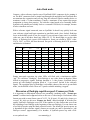
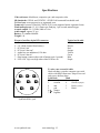
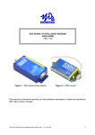
SynFlash
Signal reference generator for Syncheck™
User manual, firmware v2.0
NOTE: Firmware version 2.0 may be installed in any unmodified SynFlash unit.
Contents
1.
2.
3.
4.
5.
6.
7.
8.
9.
10.
11.
Introduction
Shooting SynFlash with your camera
Auto-Flash mode
Flash/pip repetition speed, Frames per Flash
Flash/pip duration and interlaced signals
Manual Mode
Sleep Mode
Care and feeding
Firmware upgrade
Why are different flash speeds available?
Specifications and pinout
Page 2
Page 2
Page 4
Page 4
Page 5
Page 7
Page 8
Page 8
Page 8
Page 9
Page 12
FCC Compliance
This device adheres to part 15 of the FCC Standards for test equipment as defined by
paragraph 15.3(dd), in particular paragraph 15.103(c). Operation is subject to the
following two conditions: (1) This device may not cause harmful interference, and (2)
this device must accept any interference received, including interference that may cause
undesired operation.
Changes or modifications not expressly approved by Pharoah Editorial, Inc. could void
the user’s authority to operate the equipment.
SynFlash conforms to the following standards:
EN55103-1 Electromagnetic emission
EN55103-2 Electromagnetic immunity
EN61000-4-3 RF Immunity
EN61000-4-8 Magnetic field
Some components used in SynFlash may contain lead.
www.syncheck.com
user manual pg. 1
Introduction
Install a fresh 9 volt battery and insert SynFlash into its rubber boot. The flexible rubber
boot is “pulled on” over SynFlash. Make certain the rubber boot’s swing-out foot (on the
back side) is closed flat against the back. Place the empty boot in front of you, open side
up. Insert the battery end of SynFlash into the bottom of the boot and lower SynFlash
fully into the boot while guiding the boot’s thin upper lip across the front of the white
LEDs. We use both hands. Take care not to push the LEDs too hard!
SynFlash is a companion product to Syncheck™, intended for use in front of your video
camera as part of a complete stage-to-finish synchronization check of audio and video
signals. Synflash with Syncheck™ will allow an accurate study of audio-to-video
synchronization errors at many points along the production path from initial shoot to
release. Gen-locked, precisely generated sound and light signals can be recorded by your
equipment and checked with Syncheck™ for accuracy, at any time and perhaps at a
distant location.
Use with a video reference signal for precise operation (see specifications).
Shooting SynFlash with your camera
We suggest that if you are using a tube-type camera you should iris down when SynFlash
is aimed directly at your camera! SynFlash’s white LEDs are rather bright (although
nowhere near the intensity of regular stage lighting). While we do not expect phosphor
burn due to SynFlash’s LEDs we suggest that you err on the side of caution.
SynFlash emits bright flashes with audible tones that can be recorded by your camera.
The best advice we can give about shooting SynFlash’s white LEDs with your camera is
to shoot them as tightly and fully-framed as possible. It will make no difference
whatsoever if the LEDs are in focus or not, in fact a wildly out of focus shot may actually
work best. Strive for full frames of “whiteout” within a black or very dark image. The
closer you come to achieving a perfect white/black image, the easier it will be to use
Syncheck™ later. (Syncheck™ sees large changes from dark to light as marker flashes,
thus bright objects or reflections in your image may reduce Syncheck’s ability to see the
flashes.) Sometimes a simple adjustment of the playback monitor’s brightness or contrast
controls will allow perfect results, but a bit of practice shooting and measuring BEFORE
you are in the field will be wise!
As noted, attention to how you shoot SynFlash will be rewarded later. Try to eliminate
everything except SynFlash’s LEDs from your video frame. The easiest way is to bring
SynFlash and your lens face to face, using SynFlash’s case to block everything else. It is
often helpful to iris down and/or insert a neutral density filter to darken your image.
SynFlash will work with the camera’s automatic gain on or off as long as you take care
that the LED flashes primarily dominate the image. Because automatic gain tends to clip
the brightness of the flashes and raise gain in between, it is better to turn off automatic
gain. In daylight and depending on camera lens opening size, it may also be helpful to
fashion a rough hood from a piece of cardboard or stiff paper with a hole large enough
for SynFlash to protrude through. The cardboard can be brought into contact with the lens
hood, blocking ALL light except that from SynFlash. Such a hood is simple, cheap, and
highly effective.
www.syncheck.com
user manual pg. 2
You must record audio pips from SynFlash at the same time you shoot its flashes. Turn
off automatic sound gain if possible! (Because SynFlash pips are very short, automatic
gain will almost always increase ambient, useless noise levels.) Another tip, hold your
microphone close to SynFlash’s audio transducer. A distance of a couple of inches will
work in all but the noisiest of environments. In noisy environments you will benefit by
getting the microphone as close as possible.
www.syncheck.com
user manual pg. 3
Auto-flash mode
Connect a video reference signal to one of SynFlash’s BNC connectors before turning it
on. The BNC connectors form a simple loop-through with negligible load. SynFlash does
not terminate the connection and you may loop the reference signal to another device or
terminate it with a 75-ohm terminator. (Usually a terminator is not required but proper
termination is always best practice.) The reference signal needs to be reasonably stable.
SynFlash will probably not reliably lock to a consumer VHS deck, for example, because
it lacks a timebase corrector.
With a reference signal connected, turn on SynFlash. It should very quickly lock onto
your reference signal and begin operation in auto-flash mode. Once locked, flash/pips
occur at the default speed of one per second. If your reference frame rate is a common
video rate, one of the three frame rate LEDs (24, 25, 30) should light, as per the chart
below. A flickering lock (green) LED indicates a frame rate related to NTSC video,
23.976, 29.97, or 59.94, has been detected. Except for a flickering lock LED, operation
and behavior is identical.
FPS
23.976
24.0
24
LED
25
LED
●
●
●
25.0
●
●
29.97
30.0
47.952
48.0
30
LED
●
●
50.0
59.94
60.0
●
●
●
Ø
1080i
1080p(sf)
√
√
√
√
√
√
√
√
√
√
√
√
√
√
√
720p
SD
Lock LED
☼
●
●
☼
●
☼
●
●
☼
●
√
√
√
SECAM
PAL
NTSC
√
√
√
●=continuous LED, ☼=flickering LED, other frame rates may also be possible
During auto-mode operation, the white LEDs will flash with a simultaneous audible
“pip”. We call these “flash/pips”. Each flash/pip is one video frame in duration. When
locked to progressive signals, flash/pip duration is 2 video frames. SynFlash always
powers up with flash/pip repetition speed of “1 per second” (locked to the reference
signal). The repetition speed of flash/pips is selectable whenever the unit is in auto-flash
mode, via the MODE switch. There are 5 speeds available including “stopped”.
Discussion of flash/pip repetition speed: Frames per Flash
It is important to differentiate between two potentially confusing terms. “Frames per
second” is abbreviated as fps and refers to the rate of video images. Professional video
formats run with (or near) frame rates of 24, 25, 30, 48 (rare), 50, and 60 fps (frames per
second). We also use the term “Frames per flash”, abbreviated fpf, to describe how
rapidly SynFlash’s flash/pips occur. FPF is the number of video frames that occur from
the beginning of one flash/pip to the beginning of the next flash/pip. You can choose one
of several fpf speeds using the Mode selection switch. The default fpf speed at power up
is dependent on the reference signal’s frames per second rate, and is equivalent to “one
flash per second” (approximately). For instance, if SynFlash powers up with a PAL
www.syncheck.com
user manual pg. 4
signal connected, SynFlash will automatically begin operation with a flash/pip speed of
25 frames per flash. This means there will be one flash/pip for every 25 video frames,
which is one flash per second. The Mode switch allows you to cycle through available
speeds of “one per second”, 8, 10, or 12 fpf (frames per flash), and “stopped”. For
example, 10 fpf means that a flash/pip will occur once every 10 video frames. With a
PAL reference that will be 5 flash/pips every 2 seconds. With an NTSC reference that
will be 3 flash/pips every second (approximately). Be certain you understand the
difference between flames per second (fps) and frames per flash (fpf) before
proceeding or you may become very confused!
When detecting a new reference frame rate, SynFlash will typically begin operation at a
speed of one flash/pip “per second”. For instance, if 23.976 rate is detected, SynFlash
will output a flash/pip every 24 frames. (Recall that 23.976 and 24 are operationally
identical.) If a rate of 25 or 50 is detected, SynFlash will output a flash/pip every 25 or 50
frames, respectively, which is once per second.
You may select different flash/pip speeds by momentarily pressing the Mode switch.
Each switch press will cycle to the next fpf setting. As long as SynFlash is locked to a
video reference you are free to select any of the five possible settings: 1-per-sec, stopped,
8 fpf, 10fpf, and 12fpf.
If you press and hold the mode switch, SynFlash will enter a special gen-locked Manual
slate mode that uses your most recent fpf selection. We will discuss Manual mode in a
later section.
Flash pip duration and interlaced
video fields
As we have said, when SynFlash is locked to
your reference signal, all flashes and pips are
precisely timed, turning on and off at specific
video line numbers. For purposes of discussion
we may say that a flash/pip has duration of 1
frame, but in fact each flash/pip’s start and end
points coincide with “active video” within each
frame. Flash/pip duration is actually slightly less
than a full video frame. If there is an intervening
vertical blanking interval (such as between fields
of an interlaced video frame, see box on the next
page), each flash/pip event is unbroken for its
full duration; it does not turn off for the vertical
blanking time between fields. When interlaced
video signals are in use, the Field switch selects
which video field a flash/pip shall begin on. Our
switch is labeled “F1”/“F2” on some units, or
“Lower”/“Upper”. SynFlash operation is
identical regardless of the label. There is much
confusion about which video fields are
lower/upper, odd/even, field one/field two. We
must leave it to the user to determine which
setting is appropriate. When interlaced images of
www.syncheck.com
SynFlash and interlaced video
Let us first consider NTSC. Rather than thinking of
NTSC video as 29.97 frames per second, we prefer
to think of it as 59.94 fields per second. If a flash rate
of 10 is selected, there will be one flash/pip for every
20 fields (10 frames) of video. Assuming the field
switch is set to “F1”, the white LEDs and audible pip
will turn on at the beginning of line 21, near the start
of field 1, and remain continuous through the end of
line 525, the end of field 2. The LEDs will remain lit
during the entire portion of active video of both
fields, as well as during the vertical interval
separating field 1 and field 2. If the field switch is set
to “F2” the LEDs will light at the beginning of line
283, near the start of field 2, and extinguish half way
through line 263 of the following frame. The exact
line numbers when SynFlash turns on and off are
probably unimportant to you as long as it is
understood that a camera WILL NOT see any light
from SynFlash except during the intended two video
fields.
With interlaced PAL signals the LEDs will turn on
starting with line 23 (field switch set to F2) or 336
(field switch set to F1), and extinguish half way
through line 623 (switch set to F2) or the end of line
310 (switch set to F1). As with NTSC, the exact line
numbers are relatively unimportant as long as it is
understood that a camera WILL NOT see any light
from SynFlash during any portion of frames other
than the intended one.
user manual pg. 5
SynFlash are properly reproduced, accurate Syncheck measurements can be made no
matter how the Field switch is set. If you do not know which setting is best, we suggest
setting it to F2/Upper for PAL or F1/Lower for all others.
Flash pip duration with progressive formats is 2 frames, starting with active video in
the first frame and ending with active video in the second frame. This is a limitation
of the current hardware design.
Audible pips are turned on and off exactly with the white LEDs. SynFlash’s transducer
contains a piezoelectric crystal speaker. It has a relatively short startup time such that the
time between LED turn on and first detectible sound emission is less than .3ms, a short
enough delay to be insignificant for our purposes. When recording SynFlash we highly
recommend that you place your microphone quite close to SynFlash’s transducer to
reduce time delay caused by sound propagation through air as well as to reduce the
effects of noise and reverberation from the space you are recording in. Because sound
travels through air at roughly 1 millisecond per foot, the distance between your
microphone and SynFlash can make a small but measurable sync error. By placing your
microphone within a few inches of SynFlash, both potential problems are greatly
reduced. You may choose to use SynFlash’s line level output instead of a microphone
pickup. This signal, a replica of the transducer’s output, is available on pin 5 of the DIN8
connector. In practice, a microphone is often more practical and more relevant. Also, the
crystal transducer cannot be disabled.
Large audio-video synchronization error times, like those encountered from remote
television broadcasts, can easily exceed the measurement parameters of our companion
Syncheck™ products. SynFlash supports two additional methods that can help you in
such cases. As you have probably noticed, most of our flash/pip patterns are very regular,
with some silent breaks. SynFlash uses a pattern of 12 regularly spaced flash/pips
followed by 4 “skipped” flash/pips. (Earlier firmware created 14 flash/pips followed by 2
“skipped” flash/pips.) The space during “skipped” flash/pips provides a reference point
for manual correction. For instance, 30fps video using a flash/pip speed of 10fpf results
in skipped flash/pips every 5.3 seconds. By watching and listening, a rough correction
may be manually estimated and applied. Once a rough amount of error correction has
been applied (thus bringing the remaining error to within the limits of your Syncheck™
(4 or 16 frames depending on model), final measurements and adjustments can be made
using Syncheck™ in the traditional way.
Some users may find it easier to look for the presence of a single flash/pip instead of
looking for space in an ever-repeating pattern. You may place SynFlash into a manually
triggered mode of operation (see next section), much like an electronic clapper stick, so
that an operator can trigger single flash/pips on demand. As long as a reference signal is
connected to SynFlash, all flash/pips will always be correctly synchronized to it.
www.syncheck.com
user manual pg. 6
Manual Mode
For manual “clapper stick” type of operation, the mode select switch or an externally
connected button switch (via the DIN8 jack) can be used to trigger one or more
flash/pips. As long as a valid reference signal is connected, flash/pips will be
synchronized properly to it.
There are three ways you may enter Manual mode. To enter Manual mode from Autoflash mode, press and hold the mode select switch. Within a couple of seconds SynFlash
will enter Manual Mode. The red “M” LED will light, all others will extinguish. (The
green lock LED is independent; if SynFlash is locked to your reference it will remain lit.)
You may also enter Manual mode directly at power on by holding the mode switch down
before turning on SynFlash. SynFlash will enter Manual mode silently and without a
flash. The third way to enter Manual mode is to turn on SynFlash without a reference
signal connected. You must power cycle (turn off, wait two to three seconds, turn on) to
return to Auto-flash mode.
Once in Manual mode, SynFlash waits until you press the mode select switch. When
pressed, Synflash will output one or more flash/pips. As long as you hold the switch,
flash/pips will repeat. If you entered Manual mode from Auto-flash mode (by holding the
Mode switch) the speed of repetition will be the same as when you were in auto-flash
mode. If the recalled rate is invalid for some reason, a default 1 per second rate is used.
As long as a valid reference signal is connected the flash/pips are placed precisely with
the reference’s active video lines, just as they are during Auto-flash mode. With
interlaced reference signals, the field switch determines field placement just as in Autoflash mode. If a reference is not connected, the speed of flash/pip repetition is
predetermined and the length of the flash/pips are extended to about 75 milliseconds, a
length that guarantees a video camera running at any usual video standard will record at
least one completely white frame.
When using SynFlash in manual mode it is generally possible to release the switch after
only one flash/pip, particularly with slower flash/pip speeds, however we recommend
that you allow at least two or three flash/pips, or more. Additional flash/pips will be
convenient later on when measuring with Syncheck. Also, it is possible that the
mechanical noise of the mode switch itself may be recorded by your microphone and
later mistaken as the start of a pip, giving a false synchronization error. By using several
flash/pips instead of relying on the first (and only) one, ambiguity is eliminated.
An external pushbutton may be connected to SynFlash’s DIN8 jack, between pin 7 and
pin 1 (SynFlash ground). When operating in Manual mode, the pushbutton will trigger
flash/pips exactly as the mode select switch does. Both are active. The external
pushbutton input is ignored at all other times. You can connect directly to the supplied
DIN8 cable or build your own. With our cable, connect the pushbutton between the
black (ground) and blue wires.
We have included one other function of Manual mode we call Flashlight. If you have no
reference connected to SynFlash, the field switch allows SynFlash to function as a
flashlight! Because the white LEDs draw considerable battery power, some of the
remaining circuitry including the microprocessor is placed into a low-power sleep mode.
Unfortunately, we must occasionally wake up the processor in order to read the switches
www.syncheck.com
user manual pg. 7
and discover if one of them was changed! The processor’s wakeup cycle causes a very
short “wink” of the LEDs approximately every second.
Sleep Mode
In order to save battery power further, we take advantage of some limited opportunities
for SynFlash to enter an extended low-power snooze. Snooze is entered after
approximately two minutes of unattended operation (the mode switch was not pressed).
Snooze is not allowed during Auto-flash mode except during no-flash operation (it is
easy to forget that SynFlash is turned on when it is not flashing!). While snoozing, all
outputs and LEDs are turned off and the processor enters a low power state. You can
return to normal operation by holding down the mode key briefly (less than 2 seconds
usually), or with a power cycle. Snooze is allowed during all manual mode operations.
The only indication that SynFlash is snoozing is a very brief flash of the red “M” LED
every two seconds. Battery drain is reduced but not eliminated, so you should always
power off SynFlash when not needed.
Care and Feeding
The protective rubber boot should remain on use unless you need access to the DIN-8
jack. We have designed SynFlash to accept normal wear and tear but we will not warrant
your unit against careless abuse. Switch handles can be broken off with excessive force
so take normal care when packing the unit for travel. As with any modern electronic
device, static discharge of sufficient intensity may overcome the built-in protections.
Take care to prevent static discharge into the unit, particularly into external DIN-8 plug
connections. In static-prone environments you should always discharge yourself by
touching one of the connected BNC jacks, or any metal ground point, first.
SynFlash is not waterproof! The audio transducer is not guaranteed against water
damage. If you anticipate use in the rain it is possible to cover the acoustic transducer
holes with a material such as SaatiTech’s B025Hyphobe (www.saatitech.com). This is a
mesh material that will affect acoustic output somewhat but will not allow casual water
penetration. An easier way to prevent rain damage is to operate SynFlash within a clear
plastic bag. We also suggest that you use the supplied rubber boot to retard weather entry
into the DIN-8 jack and battery compartment.
Keep a fresh battery handy. SynFlash will drain your battery if left on or accidentally
turned on during storage or travel. Full battery voltage provides brighter flashes and
louder pips.
Firmware Upgrade
Windows is required for firmware upgrade. Mac is not supported for firmware upgrade at
this time. You may download an executable file from our website and connect SynFlash
to a PC using the cable supplied (or suitable equivalent). If you do not have a DB9 serial
connection you may use a USB to serial converter. Not all work, however. (Belkin
F5U109 does NOT work!) We have tested the FTDI US232B adapter, available here:
http://www.parallax.com/detail.asp?product_id=800-00030. Many others should work.
You may send the unit to us for firmware upgrade, for the cost of shipping.
www.syncheck.com
user manual pg. 8
Why are different flash speeds available?
If you do not wish to follow the discussion in this section, we believe the default rate of
one per second is suitable for most purposes!
Three other flash/pips repetition speeds (flashes per frame) have been chosen for
SynFlash to help us identify errors during frame rate conversions. If no rate conversion
will be required, any repetition speed will work as well as any other. If you need to shoot
at one frame rate and perform some work at another there will be a frame rate conversion
involved at one or more points along the work path. Syncheck™ can help spot all errors
introduced by the conversion process but we must take care not to introduce errors in our
measurements where none actually exist. Take the case of converting from 24 fps (or
23.976) progressive to 30 fps (or 29.97) interlaced, as when shooting 24fps film and
editing on a system capable only of 30fps display. A frame rate conversion is required to
stretch those 24 frames into 30, usually via a “2:3 pull up” process. Remember as you
read that each of the 30 new frames is made up of 2 fields. There are 60 fields per second.
When converting the original 24 frames per second, half of them (every other one) are
stretched to fill more than one frame of video. One source frame becomes two video
fields. The next frame from our 24fps source is copied into three fields of the 30fps video
(1 frame of original becomes 1.5 frames of new). This alternation of one frame into 2
fields with the next frame into 3 fields is called 2:3 pull up. Chart 1 below will help
reveal how each second of the original 24 frames is distributed into 60 fields (30 frames)
of new video. Chart 1 includes two possible versions of this process, first where the first
original frame is copied to two fields and the other where the first original frame is
copied to three fields. Both are equally likely. Ignore the blue areas for the moment.
30i frames
30i fields
24p 2:3
1
1A
2
1B
30i fields
24p 2:3
24p 3:2
3
2B
1
3A
4
3B
2
1
24p 3:2
30i frames
2A
9
12A
13A
6A
14A
7A
8
7B
5
14B
15
15A
8B
9A
15B
16
16A
10A
7
17A
8
18
17B
18A
14
13
10B
8
17
16B
13
12
10
9B
7
6
12
11
9
8A
6
5
14
13B
7
6B
4
11
10
6
5B
4
13
12B
10
9
5A
3
12
11B
5
4B
3
2
11
11A
4A
19
18B
19A
15
14
Chart 1, 30-24 conversion with 5 frames per flash
Let us look at how SynFlash’s flash/pips fit into this process. If we had chosen a
SynFlash speed of 5 fpf (for the sake of discussion only, since such a rate is not available
on SynFlash!), where its white LEDs would flash every fifth frame, the chart’s blue areas
show that some flashes would be converted into only two fields while others would be
converted into 3 fields. Two noteworthy things would happen to our flashes. First, some
of them would be two fields long and some would be three fields long. Inconsistent
lengths of our new frames would not matter because Syncheck ignores the length of each
flash, but the timing between the start of each frame would be unavoidably altered at the
same time. Sometimes there would be 12 fields between flashes, other times there would
be 13 fields between flashes. This would cause half-frame “chatter” in the error reading
displayed by Syncheck. While technically accurate, it would be a variability that over
time would average to zero. The measurement chatter only serves to confuse our reading.
Instead, we are more interested in whether the overall offset between audio and video has
www.syncheck.com
user manual pg. 9
15
9B
been changed, in other words “is one consistently ahead of the other?” By selecting a
flash rate that will be consistently converted into the new rate, we can eliminate the
measurement “chatter”. To accomplish this with a 24fps reference signal, you can select
8 flashes per frame. On Chart 2 below the blue areas show where our flashes occur. You
can see that 8fpf will convert perfectly into 10 fpf when the 24 frames are converted into
30. Even though some flash frames will be converted into two fields and others into three
fields, the time between each flash start will be consistent. Looking at this from the other
direction, when working with a 30fps reference, you could choose a speed of 10 frames
per flash. 10 fpf converts evenly to 8 fpf at 24fps. In fact, it should be possible to convert
from 24 to 30 and back to 24 with no measurement “chatter” at either rate.
30i frames
30i fields
24p 2:3
1
1A
2
1B
3
2B
1
3A
4A
12A
9
13A
24p 3:2
6B
14A
7B
15A
8B
9A
16A
17A
8
18
17B
13
10B
8
17
16B
12
10A
7
16
15B
10
9B
7
6
12
11
9
8A
6
15
14B
11
10
8
7A
5
14
13B
10
9
7
6A
4
13
12B
5B
5
3
12
11B
6
5A
4
2
11
11A
5
4B
3
1
30i frames
4
3B
2
24p 3:2
30i fields
24p 2:3
2A
18A
14
13
19
18B
19A
15
14
Chart 2, 30-24 conversion with 8 frames per flash
You might have realized that a flash/pip speed of 4 (for 24fps) or 5 (for 30fps) would
work just as well as our choices of 8 (for 24fps) and 10 (for 30fps). There would be twice
as many flashes per second and Syncheck™ can accept the faster rates, but if rapid
acoustic pips are played in a highly reverberant room with long acoustic decay times
there could be trouble distinguishing one pip from the next. To reduce the likelihood of
this possibility, and increase the maximum amount of un-ambiguous error that can be
measured, we have settled on a slower speed of 8fpf.
For 25fps operation, 10 frames per flash will convert to exactly 12 fpf at 30 frames (Chart
3 below). In cases where only the playback speed is changed, such as shooting at 24 fps
but speeding up the playback to 25fps, it does not matter what flash speed is chosen
because no frame conversion is taking place.
30i frames
30i fields
25
1
1A
1A
30i frames
25p
2A
1B
2A
4
3B
2B
8A
3A
6B
6
7A
9A
7B
7
4B
3B
4A
5B
4B
10
9B
10A
8A
8B
8
6
5A
6A
5B
5
11
10B
11A
9A
11B
9B
9
6B
5A
4
9
8B
5
4A
3
8
7B
6A
3A
2
7
7A
3
2B
1
25p
30i fields
25
2
1B
12
12A
10A
12B
10B
10
Chart 3, 30-25 conversion aid
www.syncheck.com
user manual pg. 10
13
13A
14
13B
11A
11B
11
14A
14B
12A
12B
12
15
9B
If you wish to shoot at 30fps and convert to 25fps, a flash speed of 12 is best.
Another potentially troublesome conversion is between 24 and 25 fps (either direction)
with NO playback speed change (1 second = 1 second). We suggest using either 8 or 10
fpf in these cases. The typical method of converting from 24 to 25 with no time speedup
is to repeat one of the 24 frames each second, while the typical method of converting
from 25 to 24 with no time slowdown is to omit one out of every 25 frames. In either of
these circumstances we believe it is better to use one of the faster rates and then roughly
average the readings. When measuring the converted picture with Syncheck you will see
the offset value change with each flash/pip. The amount of change from one flash/pip to
the next will stay within a range of one full frame. An average offset error somewhere in
the middle of the error range is probably the best compromise. Why do we not
recommend one flash per second? We prefer to avoid the possibility that our single frame
flash will either be dropped or doubled, depending on the direction of the conversion. We
also believe more flashes per second are a better indicator of what is actually occurring.
www.syncheck.com
user manual pg. 11
Specifications
Video reference: black burst, composite sync, and composite video
SD Standards: 625PAL and 525NTSC. 625SECAM is untested but should work
Tri-level sync: most progressive or segmented scan
Frame rate: between 24 and 60 (720P24/25/30 is not supported unless segmented scan)
Flash/audio pip rate: 12, 10, 8 frames per flash/pip, 1 per second, manual trigger
Acoustic output: 2.9-3.1 KHz, 90db at 1 foot
Audio output: approx 2V p-p
Battery: 9V standard alkaline
Weight: 1 lb
Pin out of auxiliary 8-pin DIN connector
1 – Ground
2 - +9V (diode isolated from battery)
3 – PC Serial “atn”
4 – PC Serial “data out”
5 – Audio line out unbalanced, 120 ohm
6 – PC Serial “data in”
7 – Slate button (connect other side of button to pin 1 ground)
8 – LED “ON” logic out, high when white LEDs are on.
◘8 ◘7 ◘6
◘5 ◘4 ◘3
◘2 ◘1
To wire your own serial cable:
Head start hint: a popular computer uses serial
cables with DIN8 connectors. Snip off one end
and you are halfway done.
9 pin Dsub
Din8
.
2
serial out
4
Orange
3
serial in
6
Green (or purple)
4
attn
3
Red (or yellow)
5
gnd
1
Black
6
jumper
7
together
SynFlash DIN-8 jack
www.syncheck.com
Typical serial cable
Black
Brown
Red
Orange
Yellow
Green
Blue
Purple
user manual pg. 12