1
Service Manual
Datascope
Passport®
Datascope
Passport®
0070-01-0441-02_revD_srvc color.indd 1
9/26/12 9:38 AM
S e r v i ce M a n u a l
Datascope
Passport®
Datascope
Passport®
FilterLine® is a U.S. registered trademark of Oridion Medical Ltd.
Masimo SET® is a U.S. registered trademark of Masimo Corp.
MediCO2® is a registered trademark of Oridion Medical Ltd.
miniMediCO2® is a registered trademark of Oridion Medical Ltd.
Microstream® is a U.S. registered trademark of Oridion Medical Ltd.
Navigator™ is U.S. trademark of Mindray DS USA, Inc.
Nellcor® is U.S. registered trademark of Nellcor Puritan Bennett Inc.
OxiMax® is a U.S. registered trademark of Nellcor Puritan Bennett Inc.
Oxismart® is a U.S. registered trademark of Nellcor Puritan Bennett Inc.
Passport 2® is a U.S. registered trademark of Mindray DS USA, Inc.
PatientNet® is a U.S. registered trademark of GE Medical Systems Information Technologies.
Velcro® is a registered trademark of Velcro Industries B.V.
Visa® is a U.S. registered trademark of Mindray DS USA, Inc.
Copyright © Mindray DS USA, Inc. 2008. Printed in U.S.A. All rights reserved.Contents of this publication may not be
reproduced in any form without permission of Mindray DS USA, Inc.
Passport 2®/Passport 2 LT™ Service Manual
0070-10-0441
Table of Contents
Contents ........................................................................................................................................................ v
Foreword ....................................................................................................................................................... v
Note ............................................................................................................................................................. v
Warning........................................................................................................................................................ v
Operation......................................................................................................................... 1 - 1
Introduction .................................................................................................................................................... 1 - 1
Controls, Indicators And Connectors ................................................................................................................. 1 - 2
Operation...................................................................................................................................................... 1 - 2
Theory of Operation ......................................................................................................... 2 - 1
CPU Control Module ....................................................................................................................................... 2 - 2
MPC860T Host CPU, U2 .......................................................................................................................... 2 - 2
Serial Communications Channels............................................................................................................... 2 - 2
Fast Ethernet Controller............................................................................................................................. 2 - 3
Power-On Reset, U14............................................................................................................................... 2 - 3
Flash Memory, U3, U4, U5, U6, U180, U181, U182, U183 ....................................................................... 2 - 3
DRAM Memory, U8, U10......................................................................................................................... 2 - 4
RTC with CPU Supervisor.......................................................................................................................... 2 - 4
Battery Backup SRAM, U9 ........................................................................................................................ 2 - 5
Dual Port RAM, U604, U777.................................................................................................................... 2 - 5
Audio Generator Circuit, U12, U27, U13 .................................................................................................. 2 - 5
Module ID, U44 ...................................................................................................................................... 2 - 6
Tone Generator, U39............................................................................................................................... 2 - 7
LCD/CRT VGA Controller, U16................................................................................................................. 2 - 7
PCMCIA Interface.................................................................................................................................... 2 - 7
Serial EEPROM ....................................................................................................................................... 2 - 7
CO Interface Connector, J4 ...................................................................................................................... 2 - 8
Recorder Interface ................................................................................................................................... 2 - 8
CO2 Interface Connector, J23................................................................................................................... 2 - 8
NIBP Interface Connector, J25 .................................................................................................................. 2 - 8
Defib Connector, J24 ............................................................................................................................... 2 - 8
SYNC Connector, J22.............................................................................................................................. 2 - 9
Docking Connector, J9 ............................................................................................................................. 2 - 9
3.3 Volt Power ........................................................................................................................................ 2 - 9
-12 Volts DC ........................................................................................................................................... 2 - 9
Communications Processor and Support ..................................................................................................... 2 - 9
D/A Analog Outputs................................................................................................................................ 2 - 10
Analog Inputs.......................................................................................................................................... 2 - 10
SRAM .................................................................................................................................................... 2 - 10
Keypad and Rotary Knob ......................................................................................................................... 2 - 10
Control Functions..................................................................................................................................... 2 - 11
Module Bus ............................................................................................................................................ 2 - 11
Front End Module ........................................................................................................................................... 2 - 12
Power Supply.......................................................................................................................................... 2 - 12
Communication Isolation .......................................................................................................................... 2 - 12
Data Acquisition...................................................................................................................................... 2 - 12
Analog to Digital Converter ...................................................................................................................... 2 - 13
Microcontroller and Data Processing.......................................................................................................... 2 - 13
Memory ................................................................................................................................................. 2 - 14
I/O Ports and Software Register Programming ............................................................................................ 2 - 15
Signal Acquisition.................................................................................................................................... 2 - 16
Lead Fault Detection................................................................................................................................. 2 - 16
Pacer Pulse/Electrosurgical Interference Detection........................................................................................ 2 - 17
Passport 2®/Passport 2 LT™ Service Manual
0070-10-0441
i
Table of Contents
Respiration ............................................................................................................................................. 2 - 17
Invasive Blood Pressure ............................................................................................................................ 2 - 18
Temperature............................................................................................................................................ 2 - 19
Timers .................................................................................................................................................... 2 - 19
Data Packets ........................................................................................................................................... 2 - 20
TFT Display / Monochrome Interface Board and Keypad Board (P/N 0670-00-0686 or 0670-00-0726).................. 2 - 21
The EPLD Interface to the CPU Board VIA SPI .............................................................................................. 2 - 21
Video display connections ........................................................................................................................ 2 - 21
TFT Inverter Connection ............................................................................................................................ 2 - 21
Speaker connection ................................................................................................................................. 2 - 21
Encoder connection ................................................................................................................................. 2 - 21
NIBP Module (P/N 0997-00-0501) .................................................................................................................. 2 - 22
Pneumatic System Control......................................................................................................................... 2 - 22
Pressure Transducer, PT1 .......................................................................................................................... 2 - 23
Pressure Transducer, PT2 .......................................................................................................................... 2 - 23
Over-Pressure Detection............................................................................................................................ 2 - 23
Pump, M1 .............................................................................................................................................. 2 - 24
Dump Valve, V1 ...................................................................................................................................... 2 - 24
Linear Valve, V2...................................................................................................................................... 2 - 24
Primary Microcontroller, U10 .................................................................................................................... 2 - 25
Secondary Microcontroller, U4 ................................................................................................................. 2 - 25
Memory ................................................................................................................................................. 2 - 26
CMOS Static RAM................................................................................................................................... 2 - 26
CMOS EEPROM...................................................................................................................................... 2 - 27
Voltage Sources ...................................................................................................................................... 2 - 27
Host Reset............................................................................................................................................... 2 - 28
Patient Connector Board AAMI......................................................................................................................... 2 - 29
Spark Gap Suppressor ............................................................................................................................. 2 - 29
Neon Bulbs............................................................................................................................................. 2 - 29
Low-Pass Filter ......................................................................................................................................... 2 - 29
EMI Suppressor ....................................................................................................................................... 2 - 29
Patient and Power Isolation ....................................................................................................................... 2 - 29
Provide mating for ECG, Temperature and two IBP connectors ...................................................................... 2 - 29
0670-00-0682-01 ................................................................................................................................... 2 - 30
0670-00-0682-02 ................................................................................................................................... 2 - 30
Patient Connector Board H.P. ........................................................................................................................... 2 - 31
Spark Gap Suppressor ............................................................................................................................. 2 - 31
Neon Bulbs............................................................................................................................................. 2 - 31
Low-Pass Filter ......................................................................................................................................... 2 - 31
EMI Suppressor ....................................................................................................................................... 2 - 31
Patient and Power Isolation ....................................................................................................................... 2 - 31
Provide Mating for ECG, Temperature and two IBP connectors...................................................................... 2 - 31
0670-00-0680-01 ................................................................................................................................... 2 - 32
0670-00-0680-02 ................................................................................................................................... 2 - 32
Nellcor/Interface Board................................................................................................................................... 2 - 33
Recorder Interface Board (AR-42)...................................................................................................................... 2 - 33
Detailed Description................................................................................................................................. 2 - 33
XE-50 Recorder Interface Board ........................................................................................................................ 2 - 34
Cooling Fault .......................................................................................................................................... 2 - 34
Fan-Fault Sense ....................................................................................................................................... 2 - 34
Power Filtering ........................................................................................................................................ 2 - 34
XE-50 Interface........................................................................................................................................ 2 - 34
ii
0070-10-0441
Passport 2®/Passport 2 LT™ Service Manual
Table of Contents
5V Regulator (U4).................................................................................................................................... 2 - 35
Power Supply ................................................................................................................................................. 2 - 36
Part Numbers 0014-00-0250 and 0014-00-0190-01 .................................................................................. 2 - 36
Part Number 0014-00-0251..................................................................................................................... 2 - 37
Communication Isolation.................................................................................................................................. 2 - 39
El Display Interface Board ................................................................................................................................ 2 - 40
Overview ............................................................................................................................................... 2 - 40
Detailed Description................................................................................................................................. 2 - 40
Passport 2 Passive Display/Keypad Interface Board............................................................................................ 2 - 41
Overview ............................................................................................................................................... 2 - 41
Detailed Description................................................................................................................................. 2 - 41
NEC 10.4” Display/Keypad Interface Board ..................................................................................................... 2 - 43
Video Display Interface ............................................................................................................................ 2 - 43
TFT Inverter Interface ................................................................................................................................ 2 - 43
Speaker Interface .................................................................................................................................... 2 - 44
Encoder Interface .................................................................................................................................... 2 - 44
The CPLD Interface to the CPU Board VIA SPI .............................................................................................. 2 - 45
Passport 2 NIBP Module (P/N 0670-00-0730 or 0670-00-0746-01).................................................................... 2 - 46
Pneumatic System Control......................................................................................................................... 2 - 46
Pressure Transducer, PT1 .......................................................................................................................... 2 - 47
ADC, U2 ................................................................................................................................................ 2 - 47
DAC ...................................................................................................................................................... 2 - 48
Pump, M1 .............................................................................................................................................. 2 - 48
Dump Valve, V1 ...................................................................................................................................... 2 - 48
Linear Valve, V2...................................................................................................................................... 2 - 48
Over-Pressure Detection............................................................................................................................ 2 - 49
Pressure Transducer, PT2 .......................................................................................................................... 2 - 50
12VSW Circuitry, Q1, Q2 ....................................................................................................................... 2 - 50
Primary Microcontroller, U10 .................................................................................................................... 2 - 50
Secondary Microcontroller, U4 ................................................................................................................. 2 - 51
Memory ................................................................................................................................................. 2 - 52
CMOS Static RAM, U5 ............................................................................................................................ 2 - 52
CMOS EEPROM, U9 ............................................................................................................................... 2 - 52
Hardware Locks ...................................................................................................................................... 2 - 53
Reset...................................................................................................................................................... 2 - 53
Host Reset............................................................................................................................................... 2 - 53
SpO2 Interface Board (Nellcor, Nell-3™ and Masimo)......................................................................................... 2 - 54
Power Supply ................................................................................................................................................. 2 - 55
SpO2 UART Serial Interface ............................................................................................................................. 2 - 56
Panel Interface Extension Connector........................................................................................................... 2 - 56
Repair Information ........................................................................................................... 3 - 1
Introduction .................................................................................................................................................... 3 - 1
Safety Precautions........................................................................................................................................... 3 - 1
Troubleshooting Guidelines .............................................................................................................................. 3 - 7
Exchange Programs ........................................................................................................................................ 3 - 7
Special Tools Required .................................................................................................................................... 3 - 7
Disassembly Instructions................................................................................................................................... 3 - 8
Assembly and Schematic Diagrams................................................................................... 4 - 1
Replacement Parts ............................................................................................................ 5 - 1
Parts List Front Housing .................................................................................................................................... 5 - 5
Parts List Rear Housing..................................................................................................................................... 5 - 15
Communication Ports Parts List .......................................................................................................................... 5 - 25
Passport 2®/Passport 2 LT™ Service Manual
0070-10-0441
iii
Table of Contents
Calibration Procedure ....................................................................................................... 6 - 1
Calibration Introduction ................................................................................................................................... 6 - 2
Warning and Guidelines ................................................................................................................................. 6 - 2
Test Equipment and Special Tools Required........................................................................................................ 6 - 2
Description ............................................................................................................................................. 6 - 2
Diagnostics .................................................................................................................................................... 6 - 3
Diagnostic Test Menu ............................................................................................................................... 6 - 3
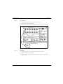
Keypad / Control Knob Test ..................................................................................................................... 6 - 4
Recorder Test .......................................................................................................................................... 6 - 5
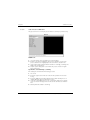
Display Tests ........................................................................................................................................... 6 - 6
Pixel Test ................................................................................................................................................ 6 - 6
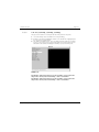
Color Test ............................................................................................................................................... 6 - 7
NIBP Tests .............................................................................................................................................. 6 - 8
Verification .................................................................................................................................................... 6 - 17
Initial Set-up ............................................................................................................................................ 6 - 17
ECG Tests............................................................................................................................................... 6 - 18
IBP 1 and IBP 2 Verification ...................................................................................................................... 6 - 20
Temperature Verification........................................................................................................................... 6 - 20
SpO2 Verification .................................................................................................................................... 6 - 20
NIBP Verification ..................................................................................................................................... 6 - 21
Battery Operation Verification ................................................................................................................... 6 - 21
Battery Back-up Verification ...................................................................................................................... 6 - 21
CO2 Operation Verification...................................................................................................................... 6 - 21
Leakage Current Tests .............................................................................................................................. 6 - 21
Preventive Maintenance.................................................................................................... 7 - 1
Preventive Maintenance Schedule ..................................................................................................................... 7 - 2
Mechanical / Physical / Visual Inspection ......................................................................................................... 7 - 2
Perform at Twelve Month Intervals.............................................................................................................. 7 - 2
Preventive Maintenance Kit .............................................................................................................................. 7 - 2
Perform Verification and NIBP Calibration – Annually ......................................................................................... 7 - 2
Perform Verification and CO2 Calibration – Annually.......................................................................................... 7 - 2
User Preventive Maintenance Introduction .......................................................................................................... 7 - 2
Care And Cleaning Of The Monitor .................................................................................................................. 7 - 3
Care and Cleaning of SpO2 Sensor .................................................................................................................. 7 - 3
Cleaning CO2 Sensors, Adapters And Sampling Components.............................................................................. 7 - 3
Sterilization and Cleaning of Reusable Cuffs ...................................................................................................... 7 - 4
Battery Replacement and Maintenance .............................................................................................................. 7 - 4
Battery Replacement ................................................................................................................................ 7 - 4
Battery Maintenance ................................................................................................................................ 7 - 4
Recorder Paper Replacement............................................................................................................................ 7 - 5
Care and Storage of Thermal Chart Paper ......................................................................................................... 7 - 5
How to Get Help ............................................................................................................................................ 7 - 6
References ..................................................................................................................................................... 7 - 7
Warranty....................................................................................................................................................... 7 - 9
USA, Canada, Mexico, and Puerto Rico..................................................................................................... 7 - 9
International (excluding North America) ..................................................................................................... 7 - 10
Manufacturer’s Responsibility ........................................................................................................................... 7 - 11
Extended Warranty......................................................................................................................................... 7 - 11
iv
0070-10-0441
Passport 2®/Passport 2 LT™ Service Manual
Contents
Introduction
Contents
Chapter
1.0 Operation ............................................................... 1-1
2.0 Theory of Operation ................................................ 2-1
3.0 Repair Information .................................................. 3-1
4.0 Assembly and Schematic Diagrams ......................... 4-1
5.0 Replacement Parts ................................................... 5-1
6.0 Calibration Procedure .............................................. 6-1
7.0 Preventive Maintenance .......................................... 7-1
Foreword
This Service Manual is intended as a guide for technically qualified personnel during repair
and calibration procedures. The information has been divided into the eight chapters listed
above. A detailed table of contents is provided on the first page of each chapter.
This publication may have been updated to reflect product design changes and/or manual
improvements. Any such changes to this manual would be accomplished by supplying
replacement pages and instructions for inserting or affixing them into the manual.
Note
Unauthorized servicing may void the remainder of the warranty. Check with the factory or
with a local authorized representative to determine the warranty status of a particular
instrument.
Warning
The Passport 2 operates on line voltages. Therefore, an electric shock hazard may exist
when the instrument covers are removed. Repair and calibration procedures should only be
performed by qualified personnel who proceed with care and follow proper servicing
techniques. Warnings are given in Chapters 4 and 7, as well as in other appropriate
locations.
Passport 2®/Passport 2 LT™ Service Manual
0070-10-0441
v
Introduction
Warning
This page intentionally left blank.
vi
0070-10-0441
Passport 2®/Passport 2 LT™ Service Manual
1.0
Operation
1.1 Introduction ................................................................................ 1-1
1.2 Controls, Indicators And Connectors ............................................ 1-2
1.3 Operation .................................................................................. 1-2
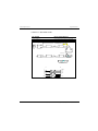
1.1
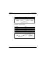
Introduction
Sections 1.2 and 1.3 are intentionally left blank. Please refer to the Operating Instructions for
complete details.
OPERATING INSTRUCTIONS
PART NUMBER
For software version V.x & earlier
Domestic
0070-00-0440-01
International
0070-00-0440-02
For software version V.x & later
Passport 2®/Passport 2 LT™ Service Manual
Domestic
0070-00-0649-01
International
0070-00-0649-02
0070-10-0441
1-1
Controls, Indicators And Connectors
1.2
Operation
Controls, Indicators And Connectors
THIS SECTION LEFT INTENTIONALLY BLANK. REFER TO THE OPERATING INSTRUCTIONS.
1.3
Operation
THIS SECTION LEFT INTENTIONALLY BLANK. REFER TO THE OPERATING INSTRUCTIONS.
1-2
0070-10-0441
Passport 2®/Passport 2 LT™ Service Manual
2.0
Theory of Operation
2.1 CPU Control Module .................................................................... 2-2
2.2 Front End Module ....................................................................... 2-12
2.3 TFT Display / Monochrome Interface Board and
Keypad Board (P/N 0670-00-0686 or 0670-00-0726) .............. 2-21
2.4 NIBP Module (P/N 0997-00-0501) .............................................. 2-22
2.5 Patient Connector Board AAMI .................................................... 2-29
2.6 Patient Connector Board H.P. ...................................................... 2-31
2.7 Nellcor/Interface Board .............................................................. 2-33
2.8 Recorder Interface Board (AR-42) ............................................... 2-33
2.9 XE-50 Recorder Interface Board .................................................. 2-34
2.10 Power Supply ........................................................................... 2-36
2.12 El Display Interface Board ......................................................... 2-40
2.13 Passport 2 Passive Display/Keypad Interface Board ................. 2-41
2.14 NEC 10.4” Display/Keypad Interface Board .............................. 2-43
2.15 Passport 2 NIBP Module
(P/N 0670-00-0730 or 0670-00-0746-01) .............................. 2-45
2.16 SpO2 Interface Board (Nellcor, Nell-3™ and Masimo) ................ 2-54
2.17 Power Supply ........................................................................... 2-55
2.18 SpO2 UART Serial Interface ...................................................... 2-56
Passport 2®/Passport 2 LT™ Service Manual
0070-10-0441
2-1
CPU Control Module
2.1
Theory of Operation
CPU Control Module
Overview
This board has the main program and system controller for the Passport 2. It also contains
the Communications Coprocessor, PCMCIA interface, RTC, Audio, CRT/LCD controller,
Serial Channels and module bus interface connectors.
2.1.1
MPC860T Host CPU, U2
Device U2, is a MPC860T Microcontroller, which contains a PowerPC core, 32 bit address
and data bus, Memory Controller (8 banks), general purpose timers, System Integration Unit
(SIU), Multi-Level Interrupts, Communications Processor module, SPI port, 100 Mbit Ethernet
Controller, and a Dual PCMCIA interface. Clock oscillator Y1, 5 Mhz, is multiplied by the
MPC860T's PLL circuit to achieve the 45MHz for Passport 2. There are six serial channels,
of which five are used. Two are full RS-232 compliant and are used for external
communications: one is used for the Recorder module; one is used to connect to the
Instrument Radio; and one is used for the Audio Synthesizer which goes to the Keypad/
Display connector.
There are eight programmable chip select/wait state control groups, only six are used. They
are listed below.
The power-on reset to the microcontroller is generated by U14, MAX814L CPU Supervisor.
The signal generated is active low for 140ms. PORESET* is generated whenever both VCC
rises from 0 to 4.75 volts and the 3.3V rises from 0 to 2.75V. The PORESET* signal is
distributed to other components that require a power on reset by using a spoke distribution
with series resistors instead of a daisy chain to better balance the signal paths. The U1 CPLD
in turn generates a HRESET* signal and a buffered BRESET* signal that is used to reset all
external components that require a reset other than PORESET*.
All high speed clock signal and control lines have series terminating resistors to reduce EMI.
2.1.2
Serial Communications Channels
There are four serial communications channels called SCC's that are part of the MPC860T's
Communication Processor Module. The following describes the function of each of them.
SCC1 - This channel is assigned to external communication use. It is buffered (U49) to RS232 levels before connection to the docking connector which is part of the base station or
comm-port system. SCC1 will operate in the standard UART mode with all hardware control
lines available.
SCC2 - This channel is assigned to external communication use. It is buffered (U50) to RS232 levels before connection to the docking connector which is part of the base station or
comm-port system. SCC2 will operate in the standard UART mode with all hardware control
lines available.
SCC3 - This channel is assigned to the Instrument Radio on connector J15.
2-2
0070-10-0441
Passport 2®/Passport 2 LT™ Service Manual
Theory of Operation
CPU Control Module
SCC4 - This channel is assigned to the serial Recorder. It operates at 3V logic levels and is
connected to Recorder Connector J8. SCC4 will operate in the standard UART mode with all
hardware control lines available.
There are two Serial management Channels called SMC's that are part of the MPC860T's
Communication Processor Module. The following describes the function of each of them.
SMC1 - Not used. Pins used as general purpose I/O.
SMC2 - This channel is assigned to Audio. The audio circuit is composed of three integrated
circuits, Wave Table Music Synthesizer, a 24 Bit Stereo D/A Converter and a one watt
Power Amplifier. It operates at 3V logic levels and is connected to the Keypad/Display J5.
SMC2 will operate in the standard UART mode with no hardware control lines available.
2.1.3
Fast Ethernet Controller
The MPC860T includes a 10/100 BASE-T Ethernet channel. The fast Ethernet Controller is
implemented independently providing fast Ethernet connectivity without effecting the
performance of the CPM. Full duplex 100 Mbps operation is supported at a system clock of
45 Mhz and higher. A 25 Mhz system clock supports 10 Mbps operation or half duplex 100
Mbps operation.
2.1.4
Power-On Reset, U14
The Power-On reset signal is created by components U14, R1, R12, R13 and Q4. The active
low power-on reset signal required by the MPC860T, as well as other components that
require reset, is generated for both logic voltages 5V and 3.3V. This keeps the CPU in reset
until the power for all the digital components are above minimum operating levels. The reset
signal PORESET is distributed in a spoke pattern with the following references, PORESET*,
POREST2*, PORESET3*, PORESET4*, and PORESET5*. The duration of the power-on reset
signal is 140ms min. The MPC860T requires only 3us minimum after power is stable and all
other components that receive this reset require less than 1ms.
2.1.5
Flash Memory, U3, U4, U5, U6, U180, U181, U182, U183
Program code is stored in eight flash memory devices configured as 2M x 32 bytes in 2
banks for a total of 16 Mbytes. These devices allow for in circuit programming via the
MPC860T background debug mode (BDM). There are no special programming voltages,
programming is done using the existing 3.3Volts.
This is one way to allow for initial factory programming as well as software upgrades.
Alternately a boot loader can be programmed into the flash parts using the BDM, and the
initial software and all upgrades can be programmed into the flash by the boot loader from
a PCMCIA memory card.
The Flash devices are configured and connected to the processor in the byte mode. The
specified access time for the Flash devices is 90nsec and will therefore require 4 wait states.
Upon reset, the MPC860T provides a boot chip select CS(0) which is hard wired to the flash
memory to allow boot of the operating software. The board support software must execute
prior to any other external or internal hardware, in order to function properly.
Passport 2®/Passport 2 LT™ Service Manual
0070-10-0441
2-3
CPU Control Module
Theory of Operation
The Flash devices are provided a buffered reset by FET Q9 and associated components. This
reset signal is generated from the MPC860T's HRESET. The reset is required to place the
Flash devices' internal state machine in a known state after power is applied for either
fetching or programming.
Bank decoding is performed by a sub-circuit of CPLD U1, and is dependent on the state of
Address line A(8) in conjunction with active CS0*.
2.1.6
DRAM Memory, U8, U10
This memory is made up of two 4M x 16 devices which form a 4M x 32 byte memory array.
These memories are volatile as well as requiring special timing and control signals, RAS*
and CAS* to operate. The type of DRAM is Fast Page Mode with an access time of 50nsec.
The special timing signals required are generated by an internal timing circuit contained in
the MPC860T. This timing generator is called Universal Programmable Machine A (UPMA).
There is another one called Universal Programmable Machine B (UPMB), which is not used.
The universal programmable machines are flexible interfaces that connect to a wide range of
memory devices, such as Fast Page Mode Dram's. At the heart of the UPM is an internal
memory RAM that specifies the logical value driven on the external memory controller pins
for each clock cycle. Each word in the RAM array provides bits that allow a memory access
to be controlled with a resolution of one quarter of the external bus clock period on the byteselect and chip-select lines. The RAM array contains 64, 32 bit words. The internal signal
timing generator loads the RAM word from the RAM array to drive the general-purpose lines,
byte-selects, and chip-selects.
The UPM RAM array is to be loaded by the board support software at power-on. The
following is UPM RAM array values to support 50nsec Fast Page Mode DRAM with the
processor operating at 50MHz.
UPMA Initializations for 50nsec DRAM's @ 50Mhz.
2.1.7
RTC with CPU Supervisor
The Real Time Clock module, BQ4847, integrates a time of day clock, a 100 year calendar,
a CPU supervisor, a battery and a crystal in a 28 pin DIP module. There are 16 registers
which contain real-time clock and alarm functions. The clock has an accuracy of +/-1 minute
per month. The duration of the power-on reset signal is 100ms min. The MPC860T requires
only 3us minimum.
Using the BQ4747’s CE out and battery voltage out, Vout, static RAM U9 is made to be nonvolatile. The internal battery powers the real time clock and maintains SRAM information in
the absence of system voltage. When an out of tolerance (4.3 to 4.5 volt) condition is
detected the BQ4747 generates an interrupt warning. The interrupt is fed to the IRQ0 NMI
input on the MPC860T. This will allow 90us min. to save any data to the non-volatile SRAM.
2-4
0070-10-0441
Passport 2®/Passport 2 LT™ Service Manual
Theory of Operation
2.1.8
CPU Control Module
Battery Backup SRAM, U9
The SRAM is configured as 128K x 8 bits and is used to store system configuration settings.
These settings are required to be non-volatile, therefore the SRAM is battery backed-up when
system power is removed. This is achieved by the battery output that is contained in the RTC
module, U7, and is outputted on pin 1.
2.1.9
Dual Port RAM, U604, U777
There is a high speed 2K x 8 Dual Port RAM with internal logic for inter-processor
communications. The device has two independent ports with separate control, address, and
I/O pins that permit independent asynchronous access for reads to any location in memory.
However, an attempt by one of the processors to access ('READ' or 'WRITE') an address
location at the same time the other processor is attempting to access the identical location
results in a 'BUSY' condition, and results in a 'write inhibit' to whichever side asserted the
chip enable last (Not all such accesses will be 'WRITE LEFT/WRITE RIGHT'). The 'BUSY'
condition is not reported to either processor in this implementation, and therefore, the
software must be designed so as to avoid the possibility of concurrent access by both
processors to an identical location.
The device is used for inter-communication between the main processor, MPC860T (U2) and
the communication processor MCF5282 (U22). Refer to the Module Bus Protocol
Specification (See Appendix).
The implementation uses the interrupt function. There are two flags, one for each side of the
DPRAM. A memory location within the DPRAM is assigned to each flag. The interrupt line to
the MPC860T is asserted when the MCF5282 writes to memory location CS1 + 0x0000
07FE. In order to reset this interrupt flag, the MPC860T must access memory location CS3
+0x0000 0FFE. Similarly, the interrupt line to the MCF5282 is asserted when the MPC860T
writes to memory location CS3 + 0x0000 0FFF. In order to reset this interrupt flag, the
MCF5282 must access memory location CS1 + 0x0000 07FF. Please note that in addition to
the flag functions described above, these two addresses are valid memory locations and may
be used for message passing.
A 5V to 3.3V conversion is performed with U777. This is to protect the DPRAM, which
cannot have 5V logic on any of its pins, even if it is not accessing the bus.
2.1.10
Audio Generator Circuit, U12, U27, U13
The audio circuit is composed of three integrated circuits, Wave Table Music Synthesizer, a
24 Bit Stereo D/A Converter and a one watt Power Amplifier.
U12 is a complete general MIDI wave table synthesizer on a single integrated circuit. The
MIDI interpreter, synthesis engine, effects processing, and all memory are included on chip.
The device receives a standard serial MIDI data stream at 31.25 +/-1% kbits/s, and outputs
a stereo 16 bit digital audio stream at 44.1kHz.
Passport 2®/Passport 2 LT™ Service Manual
0070-10-0441
2-5
CPU Control Module
Theory of Operation
The digital outputs LRCLK and SOUT from the U12 provide the clock and the digital audio
data input to the stereo D/A converter. This is a complete stereo digital to analog system
including digital interpolation, 128X third order delta-sigma D/A conversion, digital deemphasis and analog filtering. The de-emphasis circuit is not used in this application.
The stereo outputs from the U27 are summed together and is fed to the power amplifier U13,
which is a bridge connected audio power amplifier capable of delivering 1watt of
continuous average power to an 8 ohm speaker load. The circuit is optimized for a
frequency range of 100Hz to 10KHz.
2.1.11
Module ID, U44
There is a Module ID port implemented by U44 that is used to read the ID code from any
device that is connected to Docking connector, J9. These devices can be either a Base Station
or Comm Ports. Each of these devices has a unique code. The base station is hot swappable,
while the Comm Ports are not hot swappable. When any base station is connected or
removed from the Docking connector J9 using live insertion, an interrupt IRQ4* is generated.
When a Comm Port, which is not hot swappable, is powered up with a Passport 2
monitor, the module ID is read by software, and is in the flow of the start-up code. This
reading of the module ID upon power up is automatic and is not dependent on whether there
is an IRQ4* or not, or if a base station or Comm Port is connected. Therefore a duplicate
IRQ4*, which may be generated by the modules upon power up, is redundant.
This IRQ4* interrupt is falling edge triggered and can be sourced only when IRQB* is
previously low and IRQA* then follows and goes low. The state diagram for the IRQA* /
IRQB* logic is such that IRQB* must be low prior to an IRQA* falling edge. In the Comm
Ports, IRQB* is tied to GND and IRQA* is driven low after the circuitry becomes active, thus
the condition is met. In the base station, IRQB* is driven low whenever there is power
applied to the base station, and IRQA* is driven low whenever the base station is powered
AND the monitor's 3.3V power is within regulation, again, meeting the condition.
IRQA* and IRQB* (on J9-17, J9-67) are both generated external to the CPU board.
Components involved in the state control logic on the CPU board, affecting the rise time of
IRQA* and IRQB*, are components R185, R174, C427, and D9. U64 is used to generate
IRQ4*.
The signal that enables U44 to drive the Module ID field onto the data bus is MODIDCS*,
active low. It is generated by a sub-circuit of CPLD U1 by decoding Address lines A[18:20]
in conjunction with an active CS3*.
2-6
0070-10-0441
Passport 2®/Passport 2 LT™ Service Manual
Theory of Operation
2.1.12
CPU Control Module
Tone Generator, U39
The tone generator is implemented using an eight bit microcontroller. The device generates a
tone signal of 909Hz for a duration of 300ms. The tone is generated in response to the
following input conditions:
1. When the system is first turned on, the level of the MPC860T's BRESET* (same as
HRESET*) signal is monitored. If this level is detected as high, the tone is generated.
2. When an active low status signal input is detected, the tone is generated. The status
signal tone 769Hz for a duration of 300ms is generated by the MPC860T on Port A, bit
4 (PA4). The signal can be repeated as required in order to create a series of tones.
2.1.13
LCD/CRT VGA Controller, U16
The LCD/VGA controller is a SPC8110 with an integrated RAMDAC, PLL Bit Block Transfer
engine and a VL Local Bus interface. It is capable of displaying 256 colors. Support for video
modes of 640 X 480 and 800 X 600 is required. The display controller needs to be able to
drive a TFT color LCD (10.4" or 12.1") (single scan), or EL panel (dual scan), or
Monochrome LCD Passive (dual scan) and an external VGA color CRT simultaneously.
The display system consists of the LCD/CRT VGA controller (U16), clock oscillator (U65), the
programmable clock synthesizer (Y2 & U66), and video display RAM (U18 & U19). The
signals required by the various display panels are routed to the Keypad/Display board
through connector J5. The various Keypad/Display boards have specific interface connectors
for each display type, requiring only a simple one-to-one cable assembly. The display panel
identifies itself to the CPU module by connecting selected pins in the VIDSEL[4:1] field
directly to the power net. These signals are pulled down to 3VGND on the CPU module
through 33.2K resistors, and their assigned value is then read, in order to identify the panel
type.
2.1.14
PCMCIA Interface
The PCMCIA interface is a dual interface called Socket A and Socket B. The PCMCIA cards
plug into a dual stacked connector assembly, J14. The MPC860T's PCMCIA host adapter
module provides all the control logic for each PCMCIA socket interface and requires only
power switching logic and buffering. The additional external buffering allows the PCMCIA
host adapter module to support up to two PCMCIA sockets and provide electrical isolation.
Because the PCMCIA interface specification was designed around the Intel (Little Endian)
method of storing 16 bit words, a byte swapping scheme had to be employed in order to
conform to the standard. Motorola follows the Big Endian method.
2.1.15
Serial EEPROM
The memory is made up of 512 bytes of non-volatile memory. U45 is a dip part and is
socketed to allow programming the memory with an external programmer. This device is
used to store network settings. Communications from the device is done via the MPC860T's
SPI interface. To select this SPI device the MPC860T's, SPISEL signal (PB31) should be set to
logic '0'.
Passport 2®/Passport 2 LT™ Service Manual
0070-10-0441
2-7
CPU Control Module
2.1.16
Theory of Operation
CO Interface Connector, J4
This connector connects the Communications Processor Module Bus to the External Parameter
Module. In addition power (+5Vdc and +12V2) and ground are provided. The digital
signals are protected from ESD by capacitors C489 to C494.
2.1.17
Recorder Interface
The recorder interface (J8) is a serial interface which is 8 bit, 1 stop bit, no parity and a
baud rate of 38.4K. The recorder interface is implemented using the MPC860T SCC4.
The recorder is controlled by sending a series of software commands along with data over
the serial interface. The recorders electronics process the incoming commands and data and
send print information to the print head.
Hardware handshaking is provided using the RTS*/CTS* control lines. Handshaking signals
are used to control the transmission of data to the recorder and to ensure that the MPC860T
does not send another command until the current one has been processed.
The RECRST* signal is used to reset the recorder. This signal is an active low output from
PB(16) of the MPC860T and is a software control function.
There is an additional signal which is located on the connector, IRQ3*, which indicates
when data can be sent.
This connector also provides an interface to the fan for control and monitoring. There is a
control line from the MPC860T to turn the fan on or off and a status signal that indicates if its
functioning.
2.1.18
CO2 Interface Connector, J23
This connector connects the Communications Processor Module Bus to the external CO2
module. In addition power (+5 Vdc and +12V2) and ground are provided. The digital
signals are protected from ESD by capacitors C136 to C139.
2.1.19
NIBP Interface Connector, J25
This connector connects the Communications processor module bus to the external NIBP
module. In addition power (+5 Vdc, +12V2) and ground are provided.
2.1.20
Defib Connector, J24
This connector provides the interface to an external Defibrillator. SMC1 is provided if serial
communications is necessary. There is a provision to accept a logic signal that is monitored
by input PB(14) on the MPC860T. There is a provision for an analog input signal that is fed
to the 10 bit A/D converter that is contained with the Communication processor (916X1). In
addition there is a re-created analog output (ECG_OUT) of the ECG waveform and a
ECG_SYNC signal which is the E trigger from the front end electronics. The ECG_SYNC
signal which is the E trigger from the front end electronics or ECG_SYNC created by the 12
lead communications data from the Mortara card within the MPC860T. The source is
controlled by the MPC860T. All signals are filtered with T-Pole filter devices.
2-8
0070-10-0441
Passport 2®/Passport 2 LT™ Service Manual
Theory of Operation
2.1.21
CPU Control Module
SYNC Connector, J22
This connector provides the interface to an external device. There is a provision for an
analog input signal that is fed to the 10 bit A/D converter that is contained with the
Communication processor (916X1). In addition there is a re-created analog output
(ECG_OUT) of the ECG waveform and blood pressure (IBP_OUT).
2.1.22
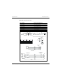
Docking Connector, J9
The docking interface connector provides the interface between the CPU Control module and
the Base Station or a Comm-Port. The main purpose of the Base Station or Comm-Port is to
provide interface connectors and some interface circuitry that is not part of the CPU Control
module. It is not feasible or practical to include all the connectors on the CPU Control module
itself. The signal groups that are part of the docking interface are shown in the table below:
2.1.23
3.3 Volt Power
The 3.3 Vdc is generated by Synchronous Step-Down Power Supply Controller U47
(MAX767) and associated discrete components. The input to the power supply controller is
+5 Vdc and its output is +3.3 Vdc +/-5% at 750ma. The controller operates a frequency of
300 Khz. The current sense resistor (R32) is connected to the controller using a Kelvin
connection (no current flow in sense lines). The current limit is controlled by current sense
resistor R32.
2.1.24
-12 Volts DC
There is a limited requirement for -12 Vdc @ 30 ma max. The supply voltage was created by
using power inverter U51 (LTC1144) operating at 10KHz. This device takes the +12V1 as
an input and generates -12 Vdc +/- 10% as an output. The -12 Vdc is used by RS-232
buffers U49 and U50 as well as Op-Amp U101.
2.1.25
Communications Processor and Support
The Communications Processor is U22, a Motorola MCF5282 microcontroller operating in
master mode. The board pulls CPRCON* low, which causes the processor to enter this mode
as it comes out of reset. The internal 64.0 MHz clock is generated by the internal synthesizer
from a 8.000 MHz reference crystal, Y600. The crystal operates with roughly sinusoidal
waveforms, and therefore generates less EMI than a square-wave oscillator module. To
further minimize EMI and avoid the need for external pull up resistors, all unneeded dynamic
I/O pins are set as outputs and disabled. This is performed at initial software boot up. This
also helps reduce power dissipation.
The purpose of the Communications Processor is to communicate with Passport 2
measurement modules such as NIBP, Front End, etc. The communications is handled over a
RS-485 module bus, where the Communications Processor is the master and everyone else is
a slave. This processor also handles scanning the front panel keypad, rotary knob, and
updating its LEDs.
Passport 2®/Passport 2 LT™ Service Manual
0070-10-0441
2-9
CPU Control Module
2.1.26
Theory of Operation
D/A Analog Outputs
There are two analog outputs for recreation of the ECG waveform and IBP measurement.
Both analog signals are created using a dual 12-bit D/A, U724 and Op-Amp, U701. The
required 4.096V reference is supplied by U638.
The ECG_OUT channel is composed of half of U701. The first stage is a low pass filter with
a gain of 2 and a level shift to allow a maximum output swing of ± 4.096V. The second
stage provides a gain of 1.25. The IBP_OUT channel is composed of half of U701. The first
stage is a low pass filter with a gain of 2 and a level shift to allow a maximum output swing
of ± 4.096V. The second stage provides a gain of 1.25 allowing the maximum amplitude to
be ± 5V. The dual 12 bit D/A converter gets its data from the Communications Processor's
SPI port qualified by PCS0. Clock and data to U724 are buffered by. The data is recreated
from measurement data received by the Communications Processor over the module bus.
2.1.27
Analog Inputs
The communications Processor has a 6 channel A/D converter, only 4 channel are used at
this time. The A/D converter is only for monitoring voltages and not for critical
measurements. AN0 and AN1 are assigned to external analog inputs. There is an attenuator
circuit provided to keep the input to the A/D within its limits. AN3 and AN4 are assigned to
measure the internal battery voltages. They also have an attenuator circuit which attenuates
the battery voltage by 1/4, to stay within the limits of the A/D converter (5 Vdc).
2.1.28
SRAM
There is 128K x 8 bytes SRAM which is used to store temporary variables and data required
by the Communications Processor.
2.1.29
Keypad and Rotary Knob
The front panel keypad is interfaced to the QSPI port qualified by PCS1. In order to read a
key, keypad scanning is used. The actual scanning logic is contained on the Interconnect
board, 0670-00-0686 and 0670-00-0714 in CPLD, U1. The keypad rows are exercised
with a Awalking zero pattern. This means that three out of four lines will always be at a logic
1 with one line driven low. In a complete cycle, each line will sequentially go low, driving a
different row on the keypad. This cycle is repeated continuously at a fast rate. The eight
columns are read, whenever a key is depressed, the coordinates of that key will be
determined by knowing which column line. The Communications Processor sends the scan
pattern on the QSPI port transmit output (MOSI) and receives the keypressed response on the
QSPI receive input (MISO). The QSPI signal are connected to the Interconnect board through
connector J5. The keypad connects to mating connectors on the Interconnect Board.
The front panel rotary selector is quadrature encoder with an integral switch. The purpose of
this device is for LCD menu scroll and selection. The quadrature signals CHA and CHB are
input from connector J5-70 and J5-71. The Communications Processor interprets the serial
data stream and sends it to the MPC860T through the Dual Port Ram, representing direction
and speed as well as the status of the integral switch.
2 - 10
0070-10-0441
Passport 2®/Passport 2 LT™ Service Manual
Theory of Operation
2.1.30
CPU Control Module
Control Functions
There is a DC/DC converter module, PS1 which provides isolated DC power to the front end
circuitry. The module can be turned on by a logic 1 on the Communications Processor port
pin PGP7.The Communications Processor reset input is controlled by a signal from the
MPC860T, port pin PA(6). The signal required for reset is a logic 1. The signal is inverted by
FET Q1 before being connected to the Communications Processor RESET* pin.
2.1.31
Module Bus
Communications with all measurement modules in the ECM is through a RS-485 module bus.
The Communications processor is the host and all modules are slave devices. The
Communications Processor UART connects to the module bus through RS-485 buffer/driver
U20. The direction of the data flow through the RS-485 buffer driver is controlled by two
different signals from port pins on the Communications Processor. Receive is controlled by an
logic 0 on port pin PGP6 and logic 0 on PGP0 Transmit is controlled by a logic 1 on PGP0
and a logic 1 on PGP6.There is a module bus connection from the isolated front end through
RS-485 buffer driver, U28. The isolation is provided by opto couplers. The front end transmit
data is provided by opto coupler U230 and receive data by opto coupler U231 along with
Q2 and part of U100. The direction of data flow is controlled by opto coupler U232 along
with part of U100.
Passport 2®/Passport 2 LT™ Service Manual
0070-10-0441
2 - 11
Front End Module
2.2
Theory of Operation
Front End Module
Overview
This document describes the theory of operation of the ECM Frontend module. This module is
responsible for acquisition of most of the patient-safety isolated signals, namely the ECG,
Respiration (by impedance), Temperature, and two channels of Invasive Blood Pressure.
The Front End Module consists of a common isolated power supply, data isolation,
microcontroller, and A/D converter, shared between the various patient signals.
2.2.1
Power Supply
The power supply takes a raw +12v DC supply voltage and generates the highly isolated
operating voltages required by the front end module. Since the input voltage varies over a +/
-5% range, some form of regulation is required. To preserve efficiency, a modular switching
supply is used.
This power supply requires sufficient isolation between the input and output to withstand the
open circuit voltage of a defibrillator, up to 5 kV. Further, it requires low capacitance
between the input and output, to minimize leakage currents which may flow should the
patient accidently contact line voltage.
2.2.2
Communication Isolation
The communication between the front end module and the host must be isolated to the same
degree as the power supply. The communications consist of an asynchronous bidirectional
serial data stream at 500 k baud. Since these signals are all digital, the isolation is
performed with optocouplers. All these devices are a special type which feature very high
isolation voltage.
2.2.3
Data Acquisition
The various signal processing blocks, such as ECG, IBP, etc., generate both analog
(waveform) and digital (status) signals. The purpose of the data acquisition system is to
capture these signals and to format them into a data stream suitable for transmission through
the communication isolation circuits. The system consists of a multiplexed analog to digital
converter, a single-chip microcontroller, and some digital level shifters. The microcontroller
serves the additional purpose of interpreting commands received from the host.
2 - 12
0070-10-0441
Passport 2®/Passport 2 LT™ Service Manual
Theory of Operation
2.2.4
Front End Module
Analog to Digital Converter
The MAX147 ADC is operated in the single ended bipolar mode, with external clock. The
control byte sent to the converter by the QSPI is %1mm, where mm is the ADC multiplexer
channel. Since the entire analog signal path is “floated” on the +2.5 volt reference, the ADC
analog common is referenced to this voltage also. The ADC therefore produces signed output
data for analog inputs corresponding to nominally ±1.25 volts around the +2.5 volt
reference. The ADC results are read into the QSPI receive RAM as words, and are leftjustified. That is, the sign bit of the ADC data is the msb of the word, and the 12 bit ADC
data is padded with 4 trailing zeros. The ADC regards the leading “1" in the command byte
as a synchronization bit. Therefore, the output data justification is controlled by the
justification of the command byte within the word transmitted by the QSPI.
2.2.5
Microcontroller and Data Processing
The Front End is controlled by U224, a Motorola MCF5282 microcontroller operating in the
single-chip mode. The board pulls RCON* high, which causes the processor to enter this
mode as it comes out of reset. The internal 64.0MHz clock is generated by the internal
synthesizer from a 8.000 MHz reference crystal. The crystal operates with roughly sinusoidal
waveforms, and therefore generates less EMI than a square-wave oscillator module. To
further minimize EMI and avoid the need for external pull up resistors, all unneeded dynamic
I/O pins are set as outputs and disabled. This is performed by programming all the unused
general purpose I/O pins as outputs at initial software boot up. This also helps reduce power
dissipation. The other default values that are set by RCON* high are: boot port size - internal
(32 bits); pad driver load - full drive strength; PLL reference - crystal; boot select - internal boot
device; PLL mode - normal.
Two SCI ports are used. The first SCI port is used to interface to the host communication
controller across the isolation barrier via the opto-couplers. The processor lies on the patient
isolated side of the barrier, and communicates using the serial module bus. The required SCI
baud rate is 500K baud. A second SCI is used to communicate to the SpO2 boards. The
third SCI is used for debugging purposes.
Power for the core is supplied by a +3.3VD switching power supply. Power for the internal
A/D converter is supplied by a +5V linear regulator. The processor is resetable by a hard
reset using several methods: 1) on power up; 2) generated locally by monitoring a voltage
supervisory chip; and 3) the provision is made to have the module bus reset from the CPU
side sent across the isolation barrier optocouplers, and then go to the microcontroller reset
pin causing a hard reset. The Communications Processor will reset all the modules on the
module bus at the beginning of its operation (after its own initialization).
A general purpose timer is used for several functions. One input capture channel is used for
the pacer detection edge capture. Two output compare channels are used to implement the
38.4KHz respiration clock. The real time ECG trigger pulse is used with a general purpose
I/O.
The periodic interrupt timer has the capability to be set to interrupt every 2ms and 0.5ms for
software ISRs.
Passport 2®/Passport 2 LT™ Service Manual
0070-10-0441
2 - 13
Front End Module
Theory of Operation
Emulation capabilities and high level debugging are included using a JTAG port configured
as a Background Debug Mode (BDM) connector. A 26-pin header connector, J204, is
provided.
Hardware multiply and accumulate (MAC) functionality for implementing the digital software
filters is provided.
No external hardware interrupts are required.
2.2.6
Memory
Since the processor operates in the single chip mode, only internal memory is used. The
device contains a ColdFire Flash Module (CFM), which is constructed with eight banks of
32K x 16-bit Flash to generate a 512-Kbyte, 32-bit wide electrically erasable and
programmable read-only memory array. The CFM is ideal for program and data storage for
single-chip applications and allows for field reprogramming without external high-voltage
sources. The voltage required to program and erase the Flash is generated internally by onchip charge pumps. Program and erase operations are performed under CPU control
through a command driven interface to an internal state machine. All Flash physical blocks
can be programmed or erased at the same time, however, it is not possible to read from a
Flash physical block while the same block is being programmed or erased. The array used in
the MCF5282 makes it possible to program or erase one pair of Flash physical blocks under
the control of software routines executing out of another pair.
Some of the requirements satisfied by the design are 8KB SRAM and 96KB Flash EEPROM.
The SRAM is used for the BOOT RAM, stack, and vector table. The Flash is used for the runtime code and satisfies the minimum of 64K, but expandable to at least 96K for ST/
Arrhythmia and future growth. The 96K is divided into 2 blocks: 8K minimum for the
bootloader code, and 88K minimum for the application code.
The Flash has a bulk erase mode. It is intended that the bootloader can be erased and
changed only at the factory, while the application code can be reloaded in the field. The
Flash has a security register, a protection register, and a lock control bit, all used to protect
the boot code from accidental erasure. For added protection, a separate external program/
erase jumper J7 is supplied, giving the capability to use jumpers for factory programming.
The jumper is connected to a general purpose I/O pin and is only read by software in order
to have permission to program the boot code. The application code is that which actually
runs the module, following initialization, and is field downloadable via the module bus. The
bootloader code performs basic initialization of the system, then passes control to the
application. The bootloader also contains support for module bus downloads of the
application code, in the event the application code is corrupted or is to be updated. The
system can always recover from a failed download, since the bootloader cannot be
accidentally erased or corrupted outside the factory.
2 - 14
0070-10-0441
Passport 2®/Passport 2 LT™ Service Manual
Theory of Operation
Front End Module
The processor is to be soldered to the board unprogrammed. Initial programming of the
bootloader is to be performed by the J204 BDM connector (Background Debug Mode). The
application code can also be installed by the BDM, or it can be downloaded via the module
bus once the bootloader is installed. Note that the BDM can also be used to facilitate board
testing, besides downloading code.
The RAM requirements are met by the internal SRAM array. The vector table lies within the
RAM. This allows the bootloader and application code to each install its own vectors at
runtime. Note that when a Flash module (in this case the bootloader module) is configured as
bootable, the initial PC, stack pointer, etc., are fetched from the module's shadow registers,
not the usual vector table. Therefore, the system is able to boot despite having undefined
RAM contents in the vector table at startup. One of the first tasks of the code is then to install
a valid vector table in the SRAM. This must be done before any exception processing can
occur.
2.2.7
I/O Ports and Software Register Programming
The interfaces to the processor are through the general purpose I/O ports, the QSPI, the SCI
(UART), and the timer ports. The internal ADC is also used for status monitoring.
General purpose I/O expansion is available principally on ports TA[2], TB[2:1], NQ,
SD[5:3], TD, TC[1:0], QS[6:4], QA[4].
Ports EL, EH, and AS[5:2] are used for microprocessor control signals and are configured as
outputs, except for Port EH bit 1, which is an input. The table below shows the bit
assignments for the ports. Port SD[2:0] is used for the SpO2 ID bits and is listed below. Ports
TA and TB are used for the general purpose timer signals and are listed below. Port QS is
used for the QSPI signals and is listed below. Ports UA, TC, and AS are used for the SCI
signals and are listed below. Port DD is used for the BDM signals, but is not listed below.
Several ports are reserved for future interfaces using external address and data bus lines.
These ports are A, B, C, D, E, F, G, H, and J. All of the unused I/O are all configured as
outputs to eliminate the need to terminate these pins to a valid logic level.
ADC inputs and general purpose I/O are provided by Port QA and QB. The ports can be
used for all the ADC signals, but have multiple functions. They can be configured with
external analog multiplexer chips to accept as many as 18 analog inputs, utilizing the
multiplexed signals MA1 and MA0 on port QA bits 1 and 0. This is used to extend the
capabilities of the internal ADC. In this design, we accept 7 ADC inputs and don't need an
external analog multiplexer chip.
The function and pin assignments of these ports are described in the tables below. The exact
function of each signal will be more fully described in the discussion of the individual signal
processing circuits. Each pin can be individually configured as an input or output. Software
performs this configuration during initialization, and no subsequent changes are made
during operation.
Passport 2®/Passport 2 LT™ Service Manual
0070-10-0441
2 - 15
Front End Module
2.2.8
Theory of Operation
Signal Acquisition
ECG
The ECG signal acquisition consists of three differential amplifier channels, which can be
configured to support either 3 lead or 5 lead operation. These are connected to channels 0
through 2 of the MAX147 ADC. In the 5 lead mode, a dedicated electrode (RL) is used for
patient drive. This allows all of the remaining electrodes (RA, LA, LL, and C) to be used for
signal acquisition. There are 7 standard vectors (“leads”) which can be obtained
simultaneously from these electrodes. However, these vectors contain much redundant
information. In fact, only 3 channels of data are required to allow derivation of any or all of
the 7 standard vectors. The ECM module bus therefore caries only lead I, Lead II, and V as
the requisite data channels. In three lead mode, only three electrodes are attached to the
patient. Further, one of these electrodes must be used for the patient drive, precluding its use
for signal acquisition. Therefore, only vectors Lead I, Lead II, and Lead III are available, with
only a single vector being available at a time. Two of the 3 differential amplifiers are
configured to acquire Lead I and Lead II. The third amplifier is reconfigurable, by means of
an analog switch, to acquire either the V lead or Lead III. The configuration of the amplifiers
and the driven lead is controlled by the two ECG lead select bits, LS0 and LS1.
2.2.9
Lead Fault Detection
Lead fault detection is performed by observing the voltage on the ECG amplifier inputs. Due
to the bias networks included in the lead buffers, an open circuited electrode will develop a
strong negative voltage. The lead fault signal is then generated by the microcontroller, which
is actively monitoring the voltage via its A/D converter.
In leads I, II, and III, the operation of the lead fault detection is very simple. When all leads
are attached, both ECG amplifier inputs are approximately at the value of the drive amplifier
bias voltage, which is about +2.5 volts nominal. This voltage is not sufficiently negative, so
no lead fault condition is indicated. If one of the active electrodes becomes detached, the
voltage on the corresponding amplifier input swings to about -5 volts. This is well beyond the
threshold, so a lead fault condition is indicated. The effect is the same if either active lead is
detached. If the drive electrode becomes detached, this is equivalent to both active leads
being open, so the operation is the same. Note that the margins between the common mode
voltage established by the drive amplifier and the lead fault threshold are large enough that
the possibility of a 300 mV electrode polarization offset does not affect lead fault detection.
Note also that this lead fault detection scheme only tests those electrodes which are
necessary to view a particular lead selection. Therefore, to view leads I, II, or III, only RA, LA,
and LL are needed. The lead fault detection is indifferent to the state of the unnecessary RL
and C electrodes.
2 - 16
0070-10-0441
Passport 2®/Passport 2 LT™ Service Manual
Theory of Operation
2.2.10
Front End Module
Pacer Pulse/Electrosurgical Interference Detection
It is necessary to detect pacer pulses so that the rate meter can be made unresponsive to
them, and so that enhancement of the pacer pulse can be indicated on the monitor display.
Electrosurgical interference is similar in nature to pacer pulses, but while a pacer pulse
occurs at a repetition rate related to the normal range of heart rates, electrosurgical noise
has much higher repetition rates, due to rapid sparking at the active electrode. Therefore, a
single circuit can detect both types of signal, and categorize the detected event as a pacer or
noise according to the repetition rate. The detection circuit processes the ECG signal present
at the I, II, and III/V outputs.
The basis for detection of the pacer pulses is frequency - the frequency content of a pacer
being assumed to be higher than any normal physiologic signal. The most difficult pacer to
discriminate would therefore be one with the lowest slew rate, that is, the slowest rise time
and smallest amplitude. From the range of pacers defined in AAMI EC13-1992, this is a
pulse amplitude of 2 mV and a duration of 2 ms. The means of performing the frequency
discrimination is shown in the figure below.
In order to identify the pacer or noise spike, a window comparator, U214, is used to detect
when the output of U212 has a moderately high frequency content signal. U212 provides
rejection of the Respiration excitation carrier, but permits passage of pacer signals. Positive
and negative input pins of this comparator are biased near half of the +5 rail voltages. The
threshold of the window is approximately 0.4 volts wide. The comparator output network
consisting of C246 and R261, provides stretching for narrow input pulses of variable width
to output pulses having a wider width. Since the window comparator is symmetrical, the
system works equally well for pacer/noise pulses of either polarity. The outputs (open
collectors tied together) are used as the pacer flag connected to the microcontroller.
2.2.11
Respiration
Respiration is obtained through the ECG electrodes by impedance pneumography, in which
the AC impedance between a pair of the ECG electrodes is monitored. This impedance
varies with the chest motions associated with breathing. The respiration signal consists of a
small modulation on the order of 1 ohm, superimposed on a much larger baseline
impedance. The baseline impedance measured at the patient has a typical value of 500
ohms, and may reach 2000 ohms. However, when AAMI connector ECG cables are used,
the cable contains 1000 ohm resistors in series with each leadwire. Since the respiration is
measured through a pair of leadwires, 2000 ohms are added to the patient impedance.
When the connector board is equipped with additional defibrillation protection provisions
(series ECG resistors and high voltage respiration coupling capacitors), the front end board
can be used with resistor less ECG cables. Therefore, the total range of baseline impedance
ranges from somewhat less than 500 to 4000 ohms.
Passport 2®/Passport 2 LT™ Service Manual
0070-10-0441
2 - 17
Front End Module
Theory of Operation
The respiration signal is isolated from the baseline by a fixed analog highpass filter at 0.1
Hz, and a lowpass at about 3 Hz. The signal is amplified and acquired by channel 3 of the
MAX147 ADC. Although the QSPI scans all channels every 2 ms, the respiration is to be
sampled at only 100 Hz. Therefore, the data processing software takes data from the QSPI
buffer in only 1 out of every 5 scans. The highpass filter is equipped with a reset function
activated by a control line in Port A. The respiration reset is controlled in a manner similar to
the ECG reset, in that it is activated whenever the respiration signal appears stuck offscale,
and must remain asserted for a settling period after the signal is brought back in range. The
baseline impedance is also monitored, by a channel in the 68HC16 internal ADC. When the
baseline impedance exceeds about 4000 ohms (patient plus cable resistors), a high
impedance flag must be set by the software. This flag indicates that the respiration signal is
no longer reliable.
When monitoring neonatal patients, it is desirable to raise the highpass corner frequency to
0.2 Hz. Since the analog filter is fixed, this is done by refiltering the signal with a digital filter
in software. In the adult mode, this digital filter remains active, but is set to a very low corner
frequency, 0.0125 Hz. Therefore, the analog 0.1 Hz filter dominates the response. This
relaxes the design constraints on the respiration filter and DC amplifier circuits, as any
residual offset voltage present in these stages is now removed by the digital filter, even in the
adult mode. In the neonatal mode, the digital filter is set to 0.155 Hz, which produces a 0.2
Hz 3 dB point when cascaded with the analog filter. A Mathcad document fully documents
the digital filter. Note that these filters are based on the 100Hz sampling rate. Whenever
software resets the analog filter, the cascaded digital filter must also be reset, or the baseline
will not settle properly. The assembler code shows the method of resetting the digital filter.
Note also that the detection of an offscale condition for reset generation must be done on the
raw ADC data, before the digital filter.
The respiration can be configured to sense impedance in either a lead I (RA/LA) or lead II
(RA/LL) axis, by means of the Respiration Lead Select bit in Port A. The respiration can be
disabled by the Respiration Enable bit in Port A. It is necessary to disable the respiration
when the carrier might cause interference with other electromedical devices. The table below
summarizes the respiration control bits in Port A.
2.2.12
Invasive Blood Pressure
An interface is provided for two standard 5mV/mmHg/V transducers. This consists of a
common excitation power source and a pair of differential amplifiers with lowpass filters,
one for each channel. The excitation source is monitored by the 68HC16 ADC, while the
pressure waveforms are acquired by the MAX147. The frequency response can be modified
by digital filters processing the acquired signals.
The excitation voltage is nominally +5 volts, but tracks the ADC reference. In this way, the
actual value of the ADC reference does not affect accuracy, since the transducer is a
ratiometric device. The excitation source has current limiting, which prevents the module
power supply from being disrupted if the transducer excitation becomes shorted. The
excitation regulator’s error amplifier output is monitored by the 68HC16 internal ADC. This
signal will abruptly jump to almost zero when the excitation source begins to current limit.
2 - 18
0070-10-0441
Passport 2®/Passport 2 LT™ Service Manual
Theory of Operation
2.2.13
Front End Module
Temperature
Patient temperature is monitored by a thermistor probe. Either YSI 400 series or 700 series
probes can be used, with autodetection of probe type. When the 400 series is used, the
temperature channel is accurate to 0.2 °C. Correct calibration is continuously verified, as is
required by European standards.
The YSI 400 series probes contain a single thermistor, wired between the tip and sleeve of a
two-circuit ¼ inch phone plug. The 700 series probes contain two thermistors, and use a
three-circuit plug. The sleeve of the plug is connected to the common of the two thermistors.
The primary thermistor is connected to the tip contact, and a secondary thermistor is
connected to the ring contact. However, only the primary thermistor is used for temperature
measurement. The secondary thermistor is used as the basis for probe type autodetection.
The ring contact of the probe socket is biased through a resistor from the +5 volt supply, and
has its voltage monitored by the 68HC16 internal ADC. When a series 400 probe is
connected, the solid metal sleeve of the plug shorts the socket’s ring contact to ground, so the
ADC reads essentially zero. If no probe is connected, the ADC reads near full scale.
However, if a series 700 probe is connected, a voltage divider is formed by the bias resistor
and the secondary thermistor. Therefore, the ADC reads an intermediate value which
depends on the probe temperature, but is easily distinguished from the readings obtained
when a 400 series probe or no probe is present.
2.2.14
Timers
The only digital input to the processor is Timer Input Compare 1 (Port GP 0), which is used for
pacer detection. This line exhibits a falling edge each time a pacer is detected. Therefore,
this input should be configured to generate an interrupt on falling edges, which invokes the
pacer handling ISR. A timer channel, rather than interrupt input, has been used so that the
exact time of arrival of the pacer is logged; this may prove helpful in generating some of the
timing based on the pacer, although it is not necessary to use this feature. The latency of the
pacer ISR must be minimized, a consideration which must be remembered when assigning
timer interrupt priorities. Timer Output Compare 1 (port GP 3) is the pacer blanking output.
When the monitor is used with patients having conventional implanted pacemakers, this
signal is not used, and is maintained at logic low. In the case of external pacemakers, a
much stronger pacer overload signal results, and the pacer blanking output is used to
activate a sample and hold of the ECG signal for the duration of the pacer overload. In
external pacer mode, TOC 1 is used to generate the pacer blanking pulse. The Pacer ISR sets
the TOC 1 output high, initiating the pulse. It further programs the TOC 1 register to
terminate the pulse after the requisite duration. Therefore, the TOC 1 function is set to drive
the pin low on timer match. Low ISR latency is necessary to ensure that the pulse starts
promptly upon pacer detection.
Timer Output Compare 2 (Port GP4) is used to define the E-trigger pulse sent to the module
bus. The E-trigger pulse is initiated by the R-wave detection software, which also programs
TOC 2 to terminate the pulse after the requisite width.
Passport 2®/Passport 2 LT™ Service Manual
0070-10-0441
2 - 19
Front End Module
Theory of Operation
The other timer channel pins (Port GP 5..7) are unused, and should be configured as outputs,
to eliminate the need for termination. However, the associated internal timer channels may
be used for software purposes, such as the 2 ms data acquisition interrupt, flash
programming timer, etc.
2.2.15
Data Packets
The data communications via the UART and communication isolation circuits are in the form
of bursts, or packets, of data.
The SCI is used to support the RS-485 module bus interface, operating at 500 kbaud. The
SCI is operated in the 9 bit mode. In the module bus protocol, ninth bits are set only when a
module address is transmitted. Most of the time, the SCI is operated in the Address Mark
Wake-Up mode. In this mode, it ignores all characters without the ninth bit set. Each time an
address is sent on the module bus, the receiver will generate an interrupt on this character.
Software must rapidly evaluate this character to determine if it matches the module address.
If it does not match, the SCI mode remains unchanged, and the bus continues to be
monitored for address characters only. However, if there is a match, the SCI must
immediately be placed in the normal receive mode, so that the rest of the poll packet can be
received and buffered. The CRC is evaluated during reception. If the poll packet CRC is
valid, the transmitter is enabled, and SCI is used to transmit a pre-buffered response packet.
Following this packet, the transmitter is disabled, and the SCI is returned to the Address Mark
Wake-Up mode. Control of the transmitter is by means of peripheral select 3 (Port PQS 6),
which is brought low to enable the RS-485 transmitter.
Because of the high data transmission speed, each of the phases of module bus
communications is best handled through a separate ISR, with the interrupt vector being
changed for each phase. This will result in faster response than could be achieved in a single
ISR with conditional code. The SCI must be the highest priority peripheral interrupt in the
system, due to the high communication speed.
2 - 20
0070-10-0441
Passport 2®/Passport 2 LT™ Service Manual
Theory of Operation
2.3
TFT Display / Monochrome Interface Board and Keypad Board (P/N 0670-00-0686 or 0670-00-0726)
TFT Display / Monochrome Interface Board and
Keypad Board (P/N 0670-00-0686 or 0670-00-0726)
Overview
This board provides interface and support for four different displays, an SPI interface to 4 X
8 matrix keypad, optical encoder and LED’s. It provides connections for an external speaker
and inverter for the display.
2.3.1
The EPLD Interface to the CPU Board VIA SPI
The purpose of the CPLD (U1) is to interface to and scan for key presses on the front panel
keypad. The method of communicating with the CPLD is the SPI port of the 68HC916X1
communications processor on the CPU control board, 0670-00-0674. The SPI interface is a
serial interface with separate serial data and clock. Data can flow in either direction using
the common clock. The communications processor is set as the master device and the CPLD
can only be a slave.
The method used to scan the keypad, which is a 4 row (J11) with up to 8 columns (J10), is a
“walking zero” pattern. This means that 3 of the 4 row/lines will always be a logic “1” with
one line driven low. In a complete cycle, each line will sequentially be driven low, driving a
different row on the keypad.
2.3.2
Video display connections
The J5 connector is the decoded video for the TFT color LCD / monochrome display based
on the board’s configuration. The 3.3 VDC input power requires additional filtering.
2.3.3
TFT Inverter Connection
The inverter for the monochrome or TFT display is connected to J3. This inverter uses the
filtered +12V2 voltage and is controlled via a 5V CMOS compatible signal.
2.3.4
Speaker connection
The system speaker is connected to J2. The Interconnect Board functions as a pass through
for this signal.
2.3.5
Encoder connection
The optical encoder for the keypad is connected to J4. Phase signals (CHA/CHB) and the
switch contact signal (SW) are passed through the interconnect board to ADC on the CPU
board.
Passport 2®/Passport 2 LT™ Service Manual
0070-10-0441
2 - 21
NIBP Module (P/N 0997-00-0501)
2.4
Theory of Operation
NIBP Module (P/N 0997-00-0501)
Overview
The NIBP PCB utilizes a Motorola MC68HC16Z1 microcontroller. This processor is
responsible for controlling a pump and two valves in the generation of the patient pressure
signal. This pressure signal is generated non-invasively using an inflatable cuff. A Fujikura
XFPM-050KPG-P2 pressure transducer converts the pressure signal in the cuff to an analog
voltage. The pressure signal is sampled by an AD7714 24-bit ADC which interfaces to the
microcontroller’s QSPI port. This data is processed by the HC16Z1 to determine the blood
pressure using the oscillometric principle. The results are then fed to the host via a RS-485
interface through the processor’s SCI port.
During a measurement, the HC16Z1 software inflates the cuff and then controls the pressure
bleed rate using a linear valve. The linear valve control allows the software to adjust the
valve orifice to arrive at a nominal linear bleed rate of 6mmHg per second. At the conclusion
of the measurement, a dump valve is opened by the software which allows the cuff pressure
to rapidly bleed down to atmosphere.
A separate Microchip PIC16C710 processor and Fujikura XFPM-050KPG-BP pressure
transducer are used to monitor the cuff pressure redundantly for safety purposes.
This document describes the details of the actual design implementation developed to meet
the specifications set forth in the PCB specification document. It provides theory of operation
and internal specification of this implementation.
2.4.1
Pneumatic System Control
The pneumatic control consists of a pressure transducer, ADC, microcontroller, DAC, and
drive circuitry. This circuitry controls a pump, a dump valve and a linear valve. The
pneumatics can also be disengaged by the over-pressure detection circuitry. The pump is
used to inflate the cuff at the beginning of each measurement cycle. Inflation pressure is
regulated by the HC16Z1 software monitoring the pressure transducer signal from PT1 via
the AD7714 ADC.
During the pump-up phase, the dump valve (V1) is closed and linear valve (V2) is modulated.
At the onset of the actual measurement phase, the linear valve is controlled to provide a
gradual reduction of the cuff pressure. The HC16Z1 software maintains the pressure bleed
rate at a nominal 6 mmHg per second, regardless of the cuff pressure or system volume.
During the measurement phase, the pressure signal acquired by the transducer PT1 is
digitized by the ADC (U2) and processed to extract the oscillometric blood pressure data. At
the conclusion of the measurement phase, the dump valve and linear valve are both fully
opened to rapidly exhaust the residual cuff pressure.
2 - 22
0070-10-0441
Passport 2®/Passport 2 LT™ Service Manual
Theory of Operation
2.4.2
NIBP Module (P/N 0997-00-0501)
Pressure Transducer, PT1
A Fujikura XFPM-050KPG-P2 transducer was selected for the measurement channel. It
provides a high level output signal which eliminates the need for an external amplifier circuit.
All that is required is a pull-up resistor and compensation capacitor. The -P2, is screened to
maximize performance in designs which will perform a zero cal before each measurement
and a yearly span cal at 150mmHg near room temperature. It also provides a nonlinearity
specification beyond the screening limits which enhances performance.
Adjusting trim pot R81 changes the attenuation factor of the transducer output signal (span
calibration). The nominal gain slope will correspond to the attenuation produced when the
wiper is at the midpoint of its range. With a 28.7kW value for R80 and a 2kW value for
R81, the nominal gain to be used by the software for the measurement channel is 11.29mV
per mmHg. The adjustment range is wide enough to cover the +/-50mV transducer set point
tolerance at the 150mmHg calibration pressure.
2.4.3
Pressure Transducer, PT2
The Fujikura XFPM-050KPG-BP transducer was selected for the over-pressure channel. Due to
a transducer accuracy of ±5.625mmHg over the entire pressure range, the overpressure
transducer must be zero calibrated at 0mmHg in order to operate the measurement duration
timer. This zero calibration must be performed at the time of manufacture, any time a
transducer is replaced, and as part of the yearly service routine for the NIBP module. The -BP
provides a high level output signal which eliminates the need for an external amplifier circuit.
All that is required is a pull-up resistor and compensation capacitor.
Adjusting trim pot R31 effectively zeros the transducer error. With 0mmHg pressure applied
to the transducer input port, R31 is adjusted until the output of the op-amp (U16) is
0.1V±1mV. With a 100kW value for R30, a 3.60kW value for R29, and a 10kW value for
R31, the nominal gain to be used by the software for the over-pressure channel is 12.44mV
per mmHg. The adjustment range is wide enough to cover the +/-67.5mV transducer set
point tolerance at the 0mmHg calibration pressure.
2.4.4
Over-Pressure Detection
There are two methods of keeping the pressure from getting too high. The first method is the
HC16Z1 software based monitoring of the pressure transducer, PT1. When the software
monitors pressure higher than, 295mmHg in Adult mode, 195mmHg in Pediatric or
145mmHg in Neonate mode, the measurement cycle will halt and dump valve, V1 and
bleed valve, V2 shall open to release the pressure in the cuff.
In the event of an over-pressure condition that is not corrected by the HC16Z1 software and
the measurement channel circuitry, the over-pressure channel serves as a fully redundant
backup system to disable the pump and valves, thus relieving the pressure in the cuff. The
hardware over pressure limit detect circuitry will deactivate the over pressure signal
12VEN*, cutting off power to the pump (M1) and valves (V1 and V2), reverting them to their
‘normally open’ state, independent of software. This action places the NIBP PCB in a
‘shutdown’ state that can be exited only by cycling the system power.
Passport 2®/Passport 2 LT™ Service Manual
0070-10-0441
2 - 23
NIBP Module (P/N 0997-00-0501)
Theory of Operation
To achieve this secondary over-pressure detection, the PCB uses a pressure transducer (PT2)
separate from the measurement channel, a secondary microprocessor (U4), and power-cut
circuitry (Q1, Q2). This circuit is also powered by a separate voltage (T5V) than used by the
AD7714 and measurement transducer.
2.4.5
Pump, M1
The pump control signal, M1EN, is provided via a PWM signal from the HC16Z1
microcontroller and is active high. This signal switches MOSFET Q3 (1/2), applying power
to the pump motor. Power to the pump (12VSW) is supplied from 12V2 via Q2. This allows
the pump to be disabled in case of a fault condition. (See section 1.1.1.3- Over-Pressure
Detection).
2.4.6
Dump Valve, V1
The dump valve, V1, is controlled by the V1EN signal provided by an active high signal from
the HC16Z1 microcontroller. This signal drives MOSFET Q3 (1/2), which switches power to
the valve coil. Power to the valve (12VSW) is supplied from 12V2 via Q2. This allows the
valve to be opened in case of a fault condition. This valve is a ‘normally open’ type, so coil
current must be supplied to cause the valve to close.
2.4.7
Linear Valve, V2
The bleed valve, V2, provides bleed down of the cuff pressure. The HC16Z1 software
maintains the pressure bleed rate at a nominal 6mmHg per second, for product specified
volumes and pressure ranges. The linear valvecan also be used to control the pump up rate
when small volume cuffs are used in the neonatal mode.
Note that this valve is a ‘normally open’ type, so coil current must be supplied to cause the
valve to close.
The linear valve’s bleed rate is current controlled by the HC16Z1 software by writing to a
Maxim MAX5352 12-bit DAC (U12) connected to a Burr-Brown OPA336 CMOS
operational amplifier (U13), in turn connected to an International Rectifier IRF7303 Power
MOSFET (Q6).
The DAC output voltage is divided by 5 (which results in a full-scale control voltage of 0.5V
nominal) which is applied to the opamp’s, U13, non-inverting input. A current sensing
resistor, R95, is used to generate a low voltage proportional to the linear valve current. This
voltage is fed back to the opamp’s inverting input. The opamp controls the Q6 FET gate
voltage to maintain the desired current setting and corresponding valve orifice. A5V is used
to generate a small offset voltage using R94 and R92 to insure the FET is fully off for a DAC
code of 0.
R95 is chosen to guarantee the full-scale current fully closes the valve under worst case
conditions, including coil winding tolerance.
2 - 24
0070-10-0441
Passport 2®/Passport 2 LT™ Service Manual
Theory of Operation
NIBP Module (P/N 0997-00-0501)
The IRF7303 MOSFET part (Q6), was chosen due to its lead-frame design which offers
superior power dissipation capabilities. As such, the maximum junction rise when driving the
0.526W, 274 ohm linear valve coil under the worst case conditions, does not warrant any
heat-sinking to achieve reasonable reliability.
2.4.8
Primary Microcontroller, U10
The NIBP PCB utilizes a Motorola MC68HC16Z1CPV16 microcontroller. This specifies a 5V,
16.78MHz, commercial temperature range part in a 144 pin TQFP package. This processor
is responsible for controlling a pump and two valves in the generation of the patient pressure
signal. This data is processed by the HC16Z1 and fed to the host via an RS-485 interface
through the processor’s SCI port.
A 32.768kHz crystal (Y1) is used for the HC16Z1 reference oscillator circuit. The HC16Z1
SYNCR (clock synthesizer control) register will be set with X=1, W=0 and Y=60. This
produces a nominal system clock frequency of 15.99MHz. The 32.768kHz crystal is
specified with a load capacitance of 20pF. To present this load, C20 and C21 are set to
33pF. The load capacitance is calculated as the series combination of C21 and C22 plus the
stray capacitance which is estimated to be less than 5pF.
At Power-On Reset, the state of the HC16Z1 pins controlling the pump and valves is such that
they are disabled (pump off / valves open).
The HC16Z1 has an internal ADC which will be used to monitor both pressure transducer
outputs, a 2.5V reference source, A5V, 12V and the switched 12V voltage, 12VSW.
Dividers are used where needed to insure the sampled voltage is within the usable ADC input
range. A filtered version of T5V is used as the ADC reference.
2.4.9
Secondary Microcontroller, U4
The PCB incorporates a Microchip Technologies PIC16LC710 to perform over-pressure
sensing.
A 2.45MHz ceramic resonator (Y2) with built-in capacitors is used for the PIC16 oscillator.
The PIC16 is informed of the desired measurement mode by reading the MODE2:0 signals
fed from the HC16Z1. It in turn sends back three signals, STATE2:0, to indicate that the
PIC16 has not encountered any faults, has set its over-pressure and measurement duration
limits to match the type of measurement indicated, and is ready for the measurement of the
type encoded on STATE2:0.
The over-pressure signal (PVO) is sampled by an ADC internal to the PIC16 at a rate of
1.196kHz. If it detects an abnormal condition, the PIC16 goes into an emergency shutdown
state. In this state, the PIC16 turns off the 12VSW power feeding the pump and valves by
toggling the 12VEN* signal line high. Since the valves are normally open, turning off their
power will vent any cuff pressure to atmosphere. The PIC16 then remains in the emergency
shutdown state until the system’s power is cycled. Note, a software reset issued from the
HC16Z1 and asserting RST* will have no effect on releasing the PIC16 from the shutdown
state.
Passport 2®/Passport 2 LT™ Service Manual
0070-10-0441
2 - 25
NIBP Module (P/N 0997-00-0501)
Theory of Operation
The ADC uses an external reference voltage (T5V). Since T5V is the same voltage source that
is powering the ratiometric transducer, direct ADC readings represent the pressure.
In addition to the input signals MODE2:0 and PVO, the PIC16 also has the 2.5V reference
voltage (25VR) applied to its A/D inputs. This signal is used as an ‘back-door’ verification of
the T5V reference voltage. Since 25VR is generated from a separate supply than T5V, and
since T5V is also used as the ADC reference voltage, if the T5V reference voltage were to
fail, the ADC would read full scale when comparing 25VR to the ADC reference (T5V).
The PIC16 device includes a brown-out reset circuit which guarantees the device is reset
when VCC is below 3.7V. As long as the PIC16LC version is used, the device is guaranteed
to be reset if its minimum allowed supply voltage is not present. This brown-out reset is
required since the PIC16 is not connected to the HC16Z1 RST*.
To increase the reliability of the PIC16 device’s function as an over-pressure detector, sleep
mode will not be utilized. This prevents the possibility of the part becoming stuck in the sleep
state.
2.4.10
Memory
Flash Memory
The program code will be stored in an Intel 28F400B5 4Mbit flash memory. The flash device
specified has the boot sector located at the bottom of the memory map at address 00000H
where the HC16Z1 expects to find the reset vectors.
Although the flash device requires additional power with CE* tied low, this prevents the need
for decoding logic where board real estate is limited.
Besides storing program code, other unprotected sectors of the flash memory may be used to
store less critical nonvolatile data if required. This would require dedicating an entire flash
sector for that purpose. However, due to small 8K byte parameter blocks in the flash, this is
not a gross waste of memory resources and prevents the need for an additional device.
2.4.11
CMOS Static RAM
The CMOS SRAM is composed of two Sony CXK58100AM 128k-word x 8-bit parts, each
with its own chip select signal, CSRAMLB* and CSRAMHB*, connected to the CS1* pins.
The HC16Z1 R/W* signal is used to activate the SRAM WE* pins while the OE* pins are
held low and the CS2 pins are held high to default the part to the read mode. Although this
much memory is unlikely to be needed during normal operation, it will help when updating
the flash in the field from the host. During this process, the HC16Z1 program code must
reside in the SRAM with additional room available for buffering data received from the host.
2 - 26
0070-10-0441
Passport 2®/Passport 2 LT™ Service Manual
Theory of Operation
2.4.12
NIBP Module (P/N 0997-00-0501)
CMOS EEPROM
The HC16Z1 also has access to a National Semiconductor NM25C020 2k-bit serial
EEPROM through its QSPI port. This EEPROM device may be used for storing PCB
identification codes or any other non-volatile information. Although a potentiometer is
currently included in the circuitry to allow span calibration of the measurement channel, the
EEPROM could optionally be used to store span calibration values for a software calibration
scheme.
The HC16Z1 software can detect bad sector data in the serial EEPROM by storing
checksums which can be verified during initialization.
2.4.13
Voltage Sources
The PCB is fed 12V and 5V (VCC) from the host through connector J1. VCC is used to power
the PCB’s digital circuitry. It is also used to generate a 2.5V reference signal (25VR) using a
Maxim MAX6125 2.5V reference (U11).
VCC can alternately be applied through J7 during in-circuit programming or debugging
procedures. VCC shall not be applied to both connectors simultaneously. VPP is applied
through J7 as the programming voltage for the PIC16.
A switched version of 12V2 (12VSW) is generated by Q2 and is used to drive the electromechanical components. This switch allows these components to be de-energized by the
PIC16 processor during an emergency shutdown. The 12V supply is also used to generate
separate, high tolerance 5 volt analog voltages, A5V and T5V, for powering the two
pressure transducer circuits. Each of these 5V voltages are generated using Maxim
MAX6250 5V references (U3 & U15).
A5V is used for the measurement channel pressure transducer and AD7714 ADC analog
supply and a divided version is used for the device reference. A5V is also used to power the
linear valve opamp control circuit.
T5V is used as the PIC16 ADC and HC16Z1 ADC reference voltages and the over-pressure
transducer supply. In addition, T5V is used as the HC16Z1 analog supply voltage (VDDA).
Passport 2®/Passport 2 LT™ Service Manual
0070-10-0441
2 - 27
NIBP Module (P/N 0997-00-0501)
2.4.14
Theory of Operation
Host Reset
The MODRESET* signal from J1 allows the host to reset the main processor (HC16Z1) on the
PCB. A NOR gate (U14) inverts the signal and the Q7 FET pulls RST* low when
MODRESET* is activated.
RST* is pulled up by R17. This resistor’s value was chosen in order to meet the RST* timing
requirements of the HC16Z1. If the RST* rise time is too slow, the HC16Z1 will assume there
is an external reset and repeatedly drive RST* low itself. This rise time is governed by the
capacitive loads on RST* as well.
VPP is pulled up to VCC by R44 during normal device operation which activates the PIC16
power-on-reset.
NOTE:
2 - 28
RST* is not connected to the PIC16 MCLR* input (VPP) in
order to prevent an HC16Z1 reset from bringing the PCB out
of the emergency shutdown state.
0070-10-0441
Passport 2®/Passport 2 LT™ Service Manual
Theory of Operation
2.5
Patient Connector Board AAMI
Patient Connector Board AAMI
The ECM Patient Connector board is intended for use with cables having integral 1k
resistors, which eliminate the possibility of harmful arc-over at the connector pins during
defibrillation.
2.5.1
Spark Gap Suppressor
The patient cable is attached to the patient connector board. The clamping of defibrillator
transients, consisting of a neon bulb with each electrode circuit which clamps the peak
voltage with respect to isolated ground in series with the coupling capacitors. The cable
resistors absorb the remaining defibrillator voltage.
2.5.2
Neon Bulbs
This board provides defibrillator overload protection in conjunction with the front-end board.
The neon bulbs has a breakdown voltage range 60 v to 75 Volts. The patient’s ECG and
Respiration signals pass through the neon bulbs, which suppresses the defibrillation pulses.
2.5.3
Low-Pass Filter
The patient cable is attached to the patient connector board. The ECG signal and the
respiration signal pass through the AAMI connector J1. This board contains 3 LC Low -Pass
Filters with a minimum roll-off frequency of 17 MHz. A cut-off frequency of 23 MHz
(-3dB)
2.5.4
EMI Suppressor
The temperature probe connects to a three-circuit phone jack connector on the Patient
Connector board. The temperature circuit provides high-precision measurements of the
thermistor resistance, while using a minimum of precise components. This module also
features electrosurgical interference suppression (ESIS) and EMI suppression. The Connector
cable is used to reduce Conducted Susceptibility and Radiated Susceptibility induced by the
high frequency fields. The module serves simply as a connector; the signals pass through
efficiently and with minimum loss.
2.5.5
Patient and Power Isolation
This power supply requires sufficient isolation between the input and output to withstand the
voltage of a defibrillator, up to 2.5 kVrms. Further, it requires low capacitance between the
input and output, to minimize leakage currents which may flow should the patient
accidentally contact line voltage. The patient’s signals in the Patient Connector board must be
isolated to the same degree as the power supply and the ground.
2.5.6
Provide mating for ECG, Temperature and two IBP connectors
The patient cable is attached to the monitor at the Patient Connector board. From the
connector board, the signal flows to the Front-End module, where the bulk of the ECG
processing is performed the transducers are plugged into the monitor via the Patient
Connector board. The Connector board bridges the excitation and ground of the transducers
together, then passes the signals to the main board.
Passport 2®/Passport 2 LT™ Service Manual
0070-10-0441
2 - 29
Patient Connector Board AAMI
2.5.7
Theory of Operation
0670-00-0682-01
This module is responsible for acquisition of most of the patient-safety-isolated signals,
namely the ECG, Temperature and two channels of Invasive Blood Pressure connectors IBP1
and IBP2. The Connector board collects all of the individual patient cables into a single
ribbon cable, then passes the signals to the main board.
2.5.8
0670-00-0682-02
This module is responsible for acquisition of the patient-safety signals, namely the ECG and
the Temperature. This module is without the dual 6 pin connectors for the IBP. The Connector
board collects all of the individual patient cables into a single ribbon cable, then passes the
signals to the main board.
2 - 30
0070-10-0441
Passport 2®/Passport 2 LT™ Service Manual
Theory of Operation
2.6
Patient Connector Board H.P.
Patient Connector Board H.P.
The ECM Patient Connector board is intended for use with cables having integral 1k
resistors, which eliminate the possibility of harmful arc-over at the connector pins during
defibrillation.
2.6.1
Spark Gap Suppressor
The patient cable is attached to the patient connector board. The clamping of defibrillator
transients, consisting of a neon bulb with each electrode circuit which clamps the peak
voltage with respect to isolated ground in series with the coupling capacitors. The cable
resistors absorb the remaining defibrillator voltage.
2.6.2
Neon Bulbs
This board provides defibrillator overload protection in conjunction with the front-end board.
The neon bulbs have a breakdown voltage range 60 v to 75 Volts. The patient’s ECG and
Respiration signals pass through the neon bulbs, which suppresses the defibrillation pulses.
2.6.3
Low-Pass Filter
The patient cable is attached to the patient connector board. The ECG signal and the
respiration signal pass through the HP connector J1. This board contains 3 LC Low -Pass
Filters with a minimum roll-off frequency of 17 MHz. A cut-off frequency of 23 MHz
(-3dB).
2.6.4
EMI Suppressor
The temperature probe connects to a three-circuit phone jack connector on the Patient
Connector board. The temperature circuit provides high-precision measurements of the
thermistor resistance, while using a minimum of precise components. This module also
features electrosurgical interference suppression (ESIS) and EMI suppression. The Connector
cable is used to reduce Conducted Susceptibility and Radiated Susceptibility induced by the
high frequency fields. The module serves simply as a connector; the signals pass through
efficiently and with minimum loss.
2.6.5
Patient and Power Isolation
This power supply requires sufficient isolation between the input and output to withstand the
voltage of a defibrillator, up to 2.5 kVrms. Further, it requires low capacitance between the
input and output, to minimize leakage currents which may flow should the patient
accidentally contact line voltage. The patient’s signals in the Patient Connector board must be
isolated to the same degree as the power supply and the ground.
2.6.6
Provide Mating for ECG, Temperature and two IBP connectors
The patient cable is attached to the monitor at the Patient Connector board. From the
connector board, the signal flows to the Front-End module, where the bulk of the ECG
processing is performed the transducers are plugged into the monitor via the Patient
Connector board. The Connector board bridges the excitation and ground of the transducers
together, then passes the signals to the main board.
Passport 2®/Passport 2 LT™ Service Manual
0070-10-0441
2 - 31
Patient Connector Board H.P.
2.6.7
Theory of Operation
0670-00-0680-01
This module is responsible for acquisition of most of the patient-safety-isolated signals,
namely the ECG, Temperature and two channels of Invasive Blood Pressure connectors IBP1
and IBP2. The Connector board collects all of the individual patient cables into a single
ribbon cable, then passes the signals to the main board.
2.6.8
0670-00-0680-02
This module is responsible for acquisition of the patient-safety signals, namely the ECG and
the Temperature. This module is without the dual 12- pin connectors for the IBP. The
Connector board collects all of the individual patient cables into a single ribbon cable, then
passes the signals to the main board.
2 - 32
0070-10-0441
Passport 2®/Passport 2 LT™ Service Manual
Theory of Operation
2.7
Nellcor/Interface Board
Nellcor/Interface Board
Overview
The Nellcor SpO2 Interface PCB provides the communication path for the two-way data flow
between the Nellcor MP-304 PCB and Passport 2 CPU Control Module. The MP-304
analyzes the analog input from the SpO2 sensor and outputs the data in digital format via a
serial digital interface. The purpose of this PCB is to control the power supplied by the control
module as well as to reassign pins for two connectors, serving as an adapter between the
two boards.
2.8
Recorder Interface Board (AR-42)
Overview
The function of this board is to provide power filtering for the recorder and suppress the
current spikes. The board also provide fan control and fan tach filtering and conversion to
logic levels that the 860T can accept.
2.8.1
Detailed Description
2.8.1.1
Power Filtering
Power filtering of the recorder logic 5VDC is provided by C5 and C6. This circuit provides a
low pass filter to reduce noise introduced into the system power. Since the load is digital
logic the current peaks are minimal.
The power filtering for the recorder motor and print head is provided by this board. It is this
board that must suppress the high current peaks from affecting the power supply and power
distribution within the system.
The suppression must reduce these peak loads to less than 1 Amp with a maximum voltage
ripple of 0.5VDC.
2.8.1.2
Fan Controller
The digital control provided by the 860T I/O pin operating as a output is conditioned by R5
& C7. This signal is then applied to the gate of Q1 which provides the drive control. The fan
is low line controlled with the fan return being connected to the FET source pin. In series with
the 12V2 is R1, 30 ohm resistor, that limits the fan voltage to approx. 9V and reduces the fan
noise. When fan operates on 12VDC it draws 100mA, typical.
2.8.1.3
Fan Sense
The Tach-generator, TG, generates two cycles of square wave per rotation of the fan motor.
The square wave is then converted to a Digital logic level, which turns on Q2 (FET). Q2’s
output is driven to Digital Logic low. The 860T uses this level to sense if the fan is functional.
If FTACH goes to Digital logic High The 860T will drive the FAN_CNTRL to Digital logic low
turning off Q1 FET removing Digital Ground from the Fan and turning it off.
Passport 2®/Passport 2 LT™ Service Manual
0070-10-0441
2 - 33
XE-50 Recorder Interface Board
Theory of Operation
2.9
XE-50 Recorder Interface Board
2.9.1
Cooling Fault
The Cooling Fault signal is driven by an FET (Q2), to the CPU to alert the CPU that a cooling
fault has occurred. A “Cooling Fan Failure” message will be displayed on the unit. The fault
can be cleared, if there is no obstruction in the fan, by cycling system power. In normal fan
operation, a pulse train is present at the SENSE pin. A missing pulse detector monitors this
pin during fan operation. A stalled, open or unconnected fan causes the TC646 to trigger its
startup timer once. If the fault persists, the FAULT output goes low, and the device is latched in
its shutdown mode. The Cooling Fault signal is also generated if there is an over-temperature
condition. That is, a temperature rise above the point where the fan's PWM control signal is
at 100%. A “Cooling Fan Failure” message will be displayed on the unit, but no action is
necessary if the temperature normalizes.
2.9.2
Fan-Fault Sense
The SENSE input (U2 pin 5) is connected to a resistor divider network (R5 & R30) to scale
down the tach pulses from the fan. During normal fan operation, a brief interruption in the
fan current generates pulses into the sense resistors network. If the device is not in Shutdown
mode, and pulses are not appearing at the SENSE input, a fault exists. The Sense Network
shall scale-down the pulses that will meet the requirements of the TC646 of 90mV minimum
at pin 5.
2.9.3
Power Filtering
Power filtering of the recorder logic 5VDC is provided by L1 together with C5 and C6. This
circuit provides a low pass filter to reduce noise introduced into the system power. Since the
load is digital logic, the current peaks are minimal. This board provides the power filtering
for the recorder motor and print head. It must suppress the high current peaks from affecting
the power supply and power distribution within the system. The suppression reduces these
peak loads to less than the recorder in-rush current with a maximum voltage ripple of
0.5VDC.
Capacitor C7 is for the purpose of reducing induced PWM switching noise. The value of this
capacitor depends on the fan current consumption. Therefore, this capacitor value may be
adjusted after lab measurements are analyzed. A provisional capacitor (C16) is included as
a placeholder with a different footprint to further aide in the elimination of the fan's
acoustical noise, if required.
2.9.4
XE-50 Interface
J4 Interfaces the XE-50 Recorder to this Module. Data is transferred serially to and from the
recorder when it gives the indication that it is ready to accept data. The signals SINEN* and
RDY* are ANDed together to produce the REC_CTS*, which is processed by the CPU for
data flow-control.
2 - 34
0070-10-0441
Passport 2®/Passport 2 LT™ Service Manual
Theory of Operation
2.9.5
XE-50 Recorder Interface Board
5V Regulator (U4)
The 5V Regulator circuit, comprised of the Micrel MIC2954 three terminal regulator, which
derives +5V from the incoming +12V (+12V2). The regulated +5V is referenced to the 12Vreturn in order to minimize the introduction motor noise generated by the fan.
Q2, Q3 and Q5 isolate the boundary between the CPU Module's circuit ground potential,
and the local ground potential. Since the two are referenced to different supply voltages,
they can be significantly different.
Passport 2®/Passport 2 LT™ Service Manual
0070-10-0441
2 - 35
Power Supply
Theory of Operation
2.10
Power Supply
2.10.1
Part Numbers 0014-00-0250 and 0014-00-0190-01
The isolated power supply takes a raw +12V2 DC supply voltage and generates the
operating voltages required by the Front End Module. Since the input voltage varies over a
+/-5% range, some form of regulation is required. To preserve efficiency, a modular
switching supply is used.
This power supply requires sufficient isolation between the input and output to withstand the
open circuit voltage of a defibrillator, up to 5 KV. Further, it requires low capacitance
between the input and output, to minimize leakage currents which may flow should the
patient accidently contact line voltage.
Operating power is to be derived from the partially regulated +12V2 supply (4.0 W max.,
including the SpO2 module interface), and output as +5.5V and -11V. Several voltages will
be generated locally on the isolated front end, including +2.5V, +3.3VD, +5V, -5V, and +5P.
Other voltages will be generated on the SpO2 interface board.
The +5.5V and -11V DC output voltages vary according to load. The major source of load
variation is the presence or absence of the invasive pressure transducers. Certain portions of
the system, such as the A/D converter, and devices interfaced to the microcontroller require a
well-regulated +5 volt supply. This is obtained from the +5.5V rail by a linear regulator,
U802, whose enable line is activated immediately upon power up. A dedicated voltage
reference device, U801, is used as the +2.5V reference voltage for the A/D converter and
other parts in the frontend. The tolerance of this regulator (0.1%) is fairly good. In the case of
the invasive pressure, the transducer excitation voltage must track the +2.5V supply.
However, because the transducer circuits are prone to being shorted (as by spilling saline
into a connector), it is not advisable to directly use the +5 volt supply to excite the
transducers. Therefore, a second power source, a very accurate voltage regulator (1.0%),
U228, has been added for the pressure excitation. A voltage comparison is performed by
U223A, and output as EXSTAT. A compensation network consisting of C289, R323, and
R957 is used. In the event that the pressure excitation should be shorted out or overloaded,
U228 will go into current limit or shutdown, disabling the IBP function, but the +5 volt supply
from U802 will not be affected, so other functions will continue to operate. The +3.3VD used
for the microcontroller power is supplied by U805, a high efficiency step down switching
power supply. The power is created from the unregulated +5.5V, and a soft start feature is
implemented to aid the microprocessor to power up smoothly. There is no enable capability
for the +3.3VD, since the microcontroller must be powered up once power is applied to the
front end. The -5V used in the patient analog section is supplied by a linear regulator, U803,
whose enable line is activated immediately upon power up.
Power being supplied to the SpO2 modules is created on the SpO2 interface board from
+5.5V and -11V, in order to eliminate any negative interaction resulting from shared
regulated power.
2 - 36
0070-10-0441
Passport 2®/Passport 2 LT™ Service Manual
Theory of Operation
Power Supply
On the Front End processor, it is crucial during power up that VDD never exceeds VDDH by
more than 0.3V. Within the processor, there are diode devices between the two voltage
domains, and violating this rule can lead to a latch-up condition. This is satisfied because it's
3.3V switching power supply runs off of +5.5V and has a slower startup, while VDDH, which
also runs off of +5.5V, is output from the voltage regulator, which comes up almost
immediately. So VDD will never exceed VDDH. Contingencies for enabling the +5V and -5V
by the microcontroller were removed to satisfy the power up sequencing on the VDDH line.
2.10.2
Part Number 0014-00-0251
The power supply can operate off of an AC line, a DC source from the Docking Station (DSDC), or two Batteries (either Sealed Lead Acid or Lithium-Ion). The power supply will
automatically select the available power source based on a specified priority.
The power supply provides 5V and 12V regulated DC output voltages. The outputs are
turned On/Off via a logic signal REMOTE-ON*.
Two independent multi-chemistry battery chargers are included in the power supply. The
chargers are capable of rapid charging up to two Sealed Lead Acid or Lithium-Ion batteries.
The chargers will be activated when AC or DS-DC power is applied.
The power supply constantly monitors various available power sources, which are selected in
the following priority order:
1. AC, or DS-DC
2. BATTERY
The total off-state current from both batteries must be less than 5 mA. During Battery
operation, the BATT-OP* output signal is set to a logic “0”. Otherwise, BATT-OP* is a logic
“1”. When operating on battery power, each battery will share the total load based on its
individual charge level.
The transfer from one source to another is seamless and occurs when the source providing
power is either disconnected or out of range.
An AC-PRESENT output signal that can drive an external LED at 10mA indicates the
presence of AC power. When AC power is applied, this output signal has an open-circuit
voltage of 20Vdc ±15%, with output equivalent impedance of 1.8k ±10%. When AC
power is not present, the AC-PRESENT output signal is 0V.
The power supply includes two independent chargers that are capable of charging 2 LithiumIon (Li-ion) batteries (P/N: 0146-00-0069) or 2 Sealed Lead Acid (SLA) batteries (P/N:
0146-00-0043).
The chargers are enabled upon application of AC, or DS-DC power and are independent of
the REMOTE-ON signal. The charger provides protection against shorted battery cells and
overly discharged batteries.
Passport 2®/Passport 2 LT™ Service Manual
0070-10-0441
2 - 37
Power Supply
Theory of Operation
The Power Supply also provides a BATT-CHARGE output signal that is a logic “1” when
either charger is active (i.e. batteries are actually being charged). Otherwise, BATTCHARGE will be a logic “0”. In addition, the signal will be logic “0” if there is a charger
fault, such as open/shorted cell(s). The BATT-CHARGE output is capable of driving an
external LED, sourcing a minimum of 10mA.
During BATTERY operation (i.e. AC and DS-DC powers are not present), the power supply
latches off when the BATTERY voltage drops below 10.3V for SLA and 9.2V for Li-Ion. The
power supply unlatches when any one of the following occurs:
• The REMOTE-ON* signal is toggled off and on, provided that valid input power (AC,
DS-DC, or BATTERY) is present.
• AC or DS-DC power is applied.
2 - 38
0070-10-0441
Passport 2®/Passport 2 LT™ Service Manual
Theory of Operation
2.11
Communication Isolation
Communication Isolation
The communication between the Front End Module and the host must be isolated to the same
degree as the power supply. The communications consist of an asynchronous bidirectional
serial data stream at 500K baud. Since these signals are all digital, the isolation is
performed with optocouplers. All these devices are a special type, which feature very high
isolation voltage.
Data is sent from the main part of the Passport 2 CPU to the Front End Module. It is
inverted twice by U100, and then buffered by Q2, so that it is capable of driving the LED
portion of optocoupler U231. The current applied to U231 is set by R47. Note that the
power for these devices is obtained from the non-isolated main +5V. The output side of U231
is connected to the isolated circuitry. Data at a +5.5V pullup level (IRXD) is obtained by the
use of pullup resistor R346. This data is connected to the UART receive data input of the
microcontroller, through a translation buffer.
The communication from the Front End Module to the CPU is very similar. The
microcontroller's UART transmit data output switches driver transistor Q204, which performs
an inversion while driving the LED portion of optocoupler U230, with the current being set by
R328. These components operate from the isolated +5.5V rails. Note that this supply is used
to power the LED, so that the current pulses do not create noise on the +3.3VD and +5V rails.
The output of the optocoupler is connected to the non-isolated circuits, where, with the
assistance of pullup resistor R48, a 5V CMOS level signal is obtained.
A transmit data enable signal is applied to Q206 so that it may drive the LED portion of
optocoupler U232, with the current being set by R354. The output of the optocoupler is
furnished with pullup resistor R58 to the non-isolated +5V supply, and drives the enable pin
of transceiver U28 through U100.
The data communication consists of brief data packets, which occur at low duty cycle.
Therefore, the communications lines spend much of the time in the idle state. Further, the
ETRIG signal is also active (only on) for very short periods. The ETRIG signal is applied
through a series resistor R864 to Q207 so that it may drive (on or off) the LED portion of
optocoupler U233, with the current being set by R65. The output of the optocoupler is
furnished with pullup resistor R72 to the non-isolated +5V supply, and directly drives two
inverters U100.
Passport 2®/Passport 2 LT™ Service Manual
0070-10-0441
2 - 39
El Display Interface Board
Theory of Operation
2.12
El Display Interface Board
2.12.1
Overview
This board provides interface and support for the EL display, an SPI interface to a 4x8 matrix
keypad, optical encoder and LED’s. It also provides connection for a speaker.
2.12.2
Detailed Description
CPLD Interface to the CPU Board Via SPI
The purpose of the CPLD (U1) is to interface to, and scan for, key presses on the front panel
keypad. The method of communicating with the CPLD is the SPI port of the 68HC916X1
communications processor on the CPU control board (0670-00-0674). The SPI interface is a
serial interface with separate serial data and clock. Data can flow either direction using a
common clock. The communications processor is set as the master device and the CPLD can
only be a slave.
Video Display Connections
The J5 connector is for the EL display. The EL display requires a 12V excitation voltage, 5V to
power the logic circuitry, and can recognize the 3.3V logic levels. Data lines LD0 through
LD7 are driven by 3.3V logic from the video processor, and filtered with 68pF capacitors to
3.3V ground to prevent ringing.
Speaker Connection
The system speaker is connected to J2. The EL Display/Keypad Interface Board functions as a
pass through for this signal.
Encoder Connection
The optical encoder for the keypad is connected to J4. Phase signals (CHA/CHB) and the
switch contact signal (SW) are passed through the EL Display/Keypad Interface Board to an
ADC on the CPU board.
VDD Control Circuit
The board employs a P-Channel FET together with a NPN Transistor to provide power
switching for the EL display’s 12V excitation. The FET is controlled by the transistor which is
switched on and off.
JTAG Connection
The board is equipped with JTAG Connector, J9, for in-circuit programming of the Keypad
Scanning CPLD.
2 - 40
0070-10-0441
Passport 2®/Passport 2 LT™ Service Manual
Theory of Operation
Passport 2 Passive Display/Keypad Interface Board
2.13
Passport 2 Passive Display/Keypad Interface Board
2.13.1
Overview
This board provides interface and support for the Passive Display, an SPI interface to a 4 x 8
matrix keypad, optical encoder and LED’s. It also provides connection for a speaker.
2.13.2
Detailed Description
CPLD Interface to the CPU Board VIA SPI
The purpose of the CPLD (U1) is to interface to, and scan for, key presses on the front panel
keypad. The method of communicating with the CPLD is the SPI port of the 68HC916X1
communications processor on the CPU control board (670-00-0674). The SPI interface is a
serial interface with separate serial data and clock. Data can flow in either direction using
the common clock. The communications processor is set as the master device and the CPLD
can only be a slave.
Video Display Connections
Connectors J12, J13 and J14 are for the passive display. J12 and Jl3 are connectors for the
display data lines and power, J14 is for the inverter. Data Lines LD0 through LD7 and UD0
through UD7 originate from the video processor and are driven by 5V logic from the
FCT162373T buffer line driver. The data lines are terminated with 61.9 ohm resistors and
filtered with 68pF capacitors to ground to prevent ringing.
Speaker Connection
The system speaker is connected to J2. The Passive Display/Keypad Interface Board
functions as a pass through for this signal.
Encoder Connection
The optical encoder for the keypad is connected to J4. Phase signals (CHA/CHB) and the
switch contact signal (SW) are passed through the Passive Display/7Keypad Interface Board
to an ADC on the CPU board.
VDD Control Circuit
The board employs a P-Channel FET together with a NPN Transistor to provide power
switching for the Passive Display’s 12V excitation. The FET is controlled by the transistor
which is switched on and off by the VIDPWR* signal from the CPU board. The circuit also
provides power filtering using an LC filter to reduce the in-rush current drawn by the display.
JTAG Connection
The board is equipped with JTAG Connector, J9 for in-circuit programming of the Keypad
Scanning CPLD.
Passport 2®/Passport 2 LT™ Service Manual
0070-10-0441
2 - 41
Passport 2 Passive Display/Keypad Interface Board
Theory of Operation
LCDBIAS Control Circuit
In order to properly turn on the passive display, the board employs a N-Channel FET which is
switched on and off by the LCDBIAS signal from the CPU board. The LCDBIAS signal is
connected to the CPLD for power sequencing. The contrast function is accomplished by
varying a 10K potentiometer.
LCDADJ Control Circuit
The contrast function is accomplished by varying a 10K potentiometer.
2 - 42
0070-10-0441
Passport 2®/Passport 2 LT™ Service Manual
Theory of Operation
2.14
NEC 10.4” Display/Keypad Interface Board
NEC 10.4” Display/Keypad Interface Board
Overview
This board provides interface and support for the 10.4” NEC Display, an SPI interface to a 4
X 8 matrix keypad, optical encoder and LED’s. It provides connections for an external
speaker and inverter for the display.
2.14.1
Video Display Interface
The video data, control signals, and display logic power are supplied to the display via the
J5 connector. The video data and control signals are generated by the video controller IC on
the CPU board (0670-00-0674) and input to buffer/line driver ICs (U7 & U8). These ICs
have 3.3V/5V logic compatible.
inputs, and 5V logic compatible outputs. These buffer/line drivers provide the proper logic
levels to the display regardless of the setting of the video processor’s LCD interface, and
ensure proper drive capability. Each video data and control signal line then passes through
an RC low pass filter designed to match line impedance and thus reduce ringing.
There are two display ID signals going to the CPU board connector, labeled VIDSEL1 and
VIDSEL2. This generates the bit pattern for the NEC 10.4” display per the following chart:
TYPE
VIDSEL1
VIDSEL2
NEC 10.4” Display
1
0
The 3.3V supply power to the display is filtered by a LC low pass filter made up of L4 and
C64. The goal of the low pass filter is to prevent the display’s operating frequency from
contaminating the 3.3V line. C59 was chosen for it’s low ESR and Ripple Current
characteristics with the capacitance value being a secondary consideration. C61 was
chosen for storing an amount of charge in order to maintain the voltage level for the LCD
logic.
2.14.2
TFT Inverter Interface
The inverter for the TFT display is connected to connector J3. The inverter is powered by
filtered +12V2 voltage and is turned on and off using the output of a monostable timer driven
from an astable timer. By varying the duty cycle of the monostable timer, the brightness of the
display is controlled. The higher the duty cycle, the brighter the display is, the lower the duty
cycle, the dimmer the display is.
The +12V2 voltage to the inverter is filtered by a LC low pass filter made up of L3 and C20.
The goal of the low pass filter is to prevent the inverter’s operating frequency from
contaminating the +12V2 line. Capacitors C57 and C58 were chosen for their low ESR and
ripple current characteristics, with the capacitance value being a secondary consideration.
Passport 2®/Passport 2 LT™ Service Manual
0070-10-0441
2 - 43
NEC 10.4” Display/Keypad Interface Board
Theory of Operation
Operation of both timers begins with both RESET lines held high. The first timer circuit
operates in an astable mode. The output of the first timer circuit is approximately 1.5ms with
a 67% duty cycle. The period and the duty cycle are determined by R58, R56 and C11. The
output of the first timer circuit is fed into the trigger input of the second timer circuit. The
second timer circuit begins it’s operation on the falling edge of the input signal. The duty
cycle is determined by the value of R59, R61 and C12. The amplitude of the output is
approximately 1.55 volts less than the power supply.
To obtain a 100% duty cycle, J8 is unjumpered. This disconnects the output of the monostable
circuit from U9 and ties the input of U9 to the voltage across R63, which is setup by the
voltage divider of R60, R62 and R63. In this configuration J6 and J7 are unjumpered. To
obtain a 50% duty cycle, J6 and J8 are jumpered, J7 is unjumpered. The combination of R59
and C12 produces the 50% duty cycle. To obtain a 75% duty cycle, J7 and J8 are jumpered
and J6 is unjumpered. The combination of R61 and C12 produces a 75% duty cycle.
The output of the monostable timer is used to drive a buffer with a 3 state output which is
controlled by VIDPWR*. In order to satisfy the input requirements of the buffer, U9, the output
of the monostable timer is stepped down by R62 and R63 for 50% and 75% duty cycles. For
the 100% duty cycle, the monostable timer is disabled and the input to U9 is stepped down
by R60, R62, R63 and +12V2. When VIDPWR* is low, U9 is turned on, providing the gate
voltage to Q1. Q1 turns on essentially shorting the gate on Q2 to ground. This turns on Q2,
providing current to flow to the control pin of the inverter, VCONT. R34 and C66 were
chosen to keep the Passport 2 CPU clock frequency (45 MHz) from contaminating the
VCONT signal and to permit a return to +12V_RET for the inverter frequency (41 KHz). R34
also provides a ground loop between 3VGND (VIDPWR*) and +12V_RET (VCONT). When
VIDPWR* is high, there is no output on U9.
R64 and C65 sustain the supply voltage for U9 as the input on U9 changes from high to low
and low to high.
CR1 provides ESD protection for the circuit from transients from the inverter.
2.14.3
Speaker Interface
The system speaker is connected to J2. The NEC 10.4” Display/Keypad Interface Board
functions as a pass through for audio signals.
2.14.4
Encoder Interface
The optical encoder for the keypad is connected to J4. Phase signals (CHA/CHB) and the
switch contact signal (SW) are passed through the NEC 10.4” Display/Keypad Interface
Board to an ADC on the CPU board.
2 - 44
0070-10-0441
Passport 2®/Passport 2 LT™ Service Manual
Theory of Operation
2.14.5
NEC 10.4” Display/Keypad Interface Board
The CPLD Interface to the CPU Board VIA SPI
The purpose of the CPLD (U1) is to interface to and scan for key presses on the front panel
keypad. The method of communicating with the CPLD is the SPI port of the 68HC916X1
communications processor on the CPU control board, 0670-00-0674-XX. The SPI interface is
a serial interface with separate serial data and clock. Data can flow in either direction using
the common clock. The communications processor is set as the master device and the CPLD
can only be a slave.
The serial input provides the keypad poll data (D0, D1, D2, D3) and LED data (XLED1-4) for
the charger and mute LED’s. This data is latched and is updated with each communication
packet and erased whenever the BRESET* is enabled. The output of the keypad Row Select is
sent to the keypad. The column selection is edge latched when a key is pressed. This data is
then serial encoded and transmitted to the Host.
The method used to scan the keypad, which is a matrix of 4 rows (J11, ROW1-4) with up to
8 columns (J10, COL1-8), is a “walking zero” pattern. This means that three out of the four
row lines will always be a logic “1” with one line driven low. In a complete cycle, each line
will sequentially be driven low, driving a different row on the keypad.
The CPLD has an 8-bit receive shift register with a latch to hold the row selection pattern
(walking zero). This completes the first part of the cycle. The next 8 bit serial data received
provides the next pattern for the row selection (walking zero) and simultaneously shifts back
the previous column pattern. If a key were pressed there would be a logic “0” in the data
shifted back for one of the columns. Since the communications processor knows which row
was a logic “0” and now has the column location, it can determine exactly which key was
pressed.
Since there are only four rows allocated to the keypad and eight select lines available, two
have been assigned to the alarm LED’s. The lines used are assigned to bits 4 and 5 of the
input serial data. Lines assigned to bits [0:3] are for the keypad and bits 6 and 7 are not
used. The LED’s can be turned on or off as well as flashed by changing the pattern of the bits
assigned.
Passive components between the CPLD and top and bottom tail connectors are needed as
follows: R15-22 are used to hold the signals high when the signal is low so that there is no
confusion about signal information. Furthermore, R7-14 as well as R23-30 are current
limiting resistors cleaning up the signal to the connectors.
The CPLD is programmed in-circuit by a cable connecting a computer to the 6 pin header, J9.
Passport 2®/Passport 2 LT™ Service Manual
0070-10-0441
2 - 45
Passport 2 NIBP Module (P/N 0670-00-0730 or 0670-00-0746-01)
2.15
Theory of Operation
Passport 2 NIBP Module (P/N 0670-00-0730 or
0670-00-0746-01)
Overview
The NIBP PCB utilizes a Motorola MC68HC16Z1 microcontroller. This processor is
responsible for controlling a pump and two valves in the generation of the patient pressure
signal. This pressure signal is generated non-invasively using an inflatable cuff. A Fujikura
XFPM-050KPG-P5 pressure transducer converts the pressure signal in the cuff to an analog
voltage. The pressure signal is sampled by an AD7714 24-bit ADC which interfaces to the
microcontroller’s QSPI port. This data is processed by the HC16Z1 to determine the blood
pressure using the oscillometric principle. The results are then fed to the host via a RS-485
interface through the processor’s SCI port.
During a measurement, the HC16Z1 software inflates the cuff and then controls the pressure
bleed rate using a linear valve. The linear valve control allows the software to adjust the
valve orifice to arrive at a nominal linear bleed rate of 6mmHg per second. At the conclusion
of the measurement, a dump valve is opened by the software which allows the cuff pressure
to rapidly bleed down to atmosphere.
A separate Atmel AVR microcontroller (AT90S4433-8AC) and Fujikura XFPM-050KPG-BP3
pressure transducer are used to monitor the cuff pressure redundantly for safety purposes.
This document describes the details of the actual design implementation developed to meet
the requirements set forth in the module requirements document. It provides theory of
operation and internal specification of this implementation.
2.15.1
Pneumatic System Control
The pneumatic control consists of a pressure transducer, ADC, microcontroller, DAC, and
drive circuitry. This circuitry controls a pump, a dump valve and a linear valve. The
pneumatics can also be disengaged by the over-pressure detection circuitry. (See section
2.15.8) The pump is used to inflate the cuff at the beginning of each measurement cycle.
Inflation pressure is regulated by the HC16Z1 software monitoring the pressure transducer
signal from PT1 via the AD7714 ADC.
During the pump-up phase, the dump valve (V1) is closed and linear valve (V2) is modulated.
At the onset of the actual measurement phase, the linear valve is controlled to provide a
gradual reduction of the cuff pressure. The HC16Z1 software maintains the pressure bleed
rate at a nominal 6mmHg per second, regardless of the cuff pressure or system volume.
During the measurement phase, the pressure signal acquired by the transducer PT1 is
digitized by the ADC (U2) and processed to extract the oscillometric blood pressure data. At
the conclusion of the measurement phase, the dump valve and linear valve are both fully
opened to rapidly exhaust the residual cuff pressure.
2 - 46
0070-10-0441
Passport 2®/Passport 2 LT™ Service Manual
Theory of Operation
2.15.2
Passport 2 NIBP Module (P/N 0670-00-0730 or 0670-00-0746-01)
Pressure Transducer, PT1
A Fujikura XFPM-050KPG-P5 transducer was selected for the measurement channel. It
provides a high level output signal which eliminates the need for an external amplifier circuit.
All that is required is a pull-up resistor and compensation capacitor. The PT1 is screened to
maximize performance in designs which will perform a zero cal before each measurement
and a yearly span cal at 150mmHg near room temperature. It also provides a nonlinearity
specification beyond the screening limits which enhances performance.
The transducer is not installed during the initial PCB manufacturing and cleaning processes,
avoiding exposure to moisture which may effect its performance, but will be soldered in
place during final module assembly.
The transducer has an output transfer characteristic of 11.667mV/mmHg. Adjusting trim pot
R81 changes the attenuation factor of the transducer output signal (span calibration), and
thus the slope of the transfer characteristic. The nominal slope will correspond to the
attenuation produced when the wiper is at the midpoint of its range. With a 28.7kW value
for R80 and a 2kW value for R81, the nominal slope to be used by the software for the
measurement channel is 11.29mV per mmHg. The adjustment range is wide enough to cover
the +/-50mV transducer set point tolerance at the 150mmHg calibration pressure.
2.15.3
ADC, U2
The pressure signal is sampled by an Analog Devices AD7714 24-bit ADC which interfaces
to the microcontroller’s QSPI port.
The device must first be configured by using the AD7714 zero-scale self-calibration mode
followed by the full-scale self-calibration mode. From this calibration process, offset and gain
coefficients are determined that will be applied automatically by the AD7714 hardware.
NOTE:
Several samples must be read before the new coefficients
are applied after a calibration.
The system zero cal is then performed. If in the span calibration diagnostic mode the system
zero cal is followed by the span cal.
NOTE:
A 90 second warm-up period shall elapse prior to span
calibration to account for transducer warm-up drift. It is also
necessary to calibrate the ADC prior to system span cal.,
otherwise the gain coefficient in the ADC will not be taken
into account during the span calibration.
The ADC is used in the bipolar mode which causes the ADC gain error to be of opposite sign
above and below the 2.5V nominal voltage appearing on AIN2. That is, the ADC gain error
pivots at 2.5V. The trim pot (R81), on the other hand, adjusts for gain error which pivots at
0V and will not correctly account for ADC gain error without a corresponding change in the
offset value. This leads to an iterative process for adjusting ADC gain error and offset.
The input buffer reduces the input range below what is required, so the BUFFER control pin is
tied low to short out the internal buffer.
Passport 2®/Passport 2 LT™ Service Manual
0070-10-0441
2 - 47
Passport 2 NIBP Module (P/N 0670-00-0730 or 0670-00-0746-01)
Theory of Operation
R15 and R27 are +/-0.1% tolerance, +/-25ppm/°C resistors which form a highly accurate
and stable voltage divider generating the AD7714 2.5V reference voltage from A5V. Since
the PT1 measurement channel transducer output is ratiometric with A5V, the AD7714
readings are directly proportional to the applied pressure after subtracting the zero offset.
The DRDY* signal is used to indicate to the HC16Z1 software that the converted data is
available. The AD7714’s POL input is tied low, so the HC16Z1 QSPI shall be configured in
the master mode with its CPOL bit set to 0 and its CPHA bit set to 1 for ADC data transfers.
The nominal ADC clock rate is 2MHz.
2.15.4
DAC
The linear valve’s bleed rate is current controlled by the HC16Z1 software by writing to a
Maxim MAX5352 12-bit DAC (U12) connected to a Burr-Brown OPA336 CMOS
operational amplifier (U13), in turn connected to an International Rectifier IRF7303 Power
MOSFET (Q6).
A DAC code of 0 will result in zero current flow in Q6, and a fully opened valve. A full-scale
DAC code results in the maximum DAC output voltage of 2.5V and thus maximum current
flow in Q6. This corresponds to a fully closed valve. Power-on-reset clears the DAC’s output
to 0 thus fully opening the valve. The DAC’s 2.5V reference voltage is derived from a Linear
Technology part, LT1790-2.5.
2.15.5
Pump, M1
The pump control signal, M1EN, is provided via a PWM signal from the HC16Z1
microcontroller and is active high. This signal switches MOSFET Q3 (1/2), applying power
to the pump motor. Power to the pump (12VSW) is supplied from 12V2 via Q2. This allows
the pump to be disabled in case of a fault condition.
2.15.6
Dump Valve, V1
The dump valve, V1, is controlled by the V1EN signal provided by an active high signal from
the HC16Z1 microcontroller. This signal drives MOSFET Q3 (1/2), which switches power to
the valve coil. Power to the valve (12VSW) is supplied from 12V2 via Q2. This allows the
valve to be opened in case of a fault condition. This valve is a ‘normally open’ type, so coil
current must be supplied to cause the valve to close.
2.15.7
Linear Valve, V2
The linear valve, V2, provides bleed down of the cuff pressure. The HC16Z1 software
maintains the pressure bleed rate at a nominal 6mmHg per second, for product specified
volumes and pressure ranges. The linear valve can also be used to control the pump up rate
when small volume cuffs are used in the neonatal mode.
Note that this valve is a ‘normally open’ type, so coil current must be supplied to cause the
valve to close.
2 - 48
0070-10-0441
Passport 2®/Passport 2 LT™ Service Manual
Theory of Operation
Passport 2 NIBP Module (P/N 0670-00-0730 or 0670-00-0746-01)
The linear valve’s bleed rate is current controlled by the HC16Z1 software by writing to a
Maxim MAX5352 12-bit DAC (U12) connected to a Burr-Brown OPA336 CMOS
operational amplifier (U13), in turn connected to an International Rectifier IRF7303 Power
MOSFET (Q6).
The DAC output voltage is divided by 5 (which results in a full-scale control voltage of 0.5V
nominal) which is applied to the opamp’s, U13, non-inverting input. A current sensing
resistor, R95, is used to generate a low voltage proportional to the linear valve current. This
voltage is fed back to the opamp’s inverting input. The opamp controls the Q6 FET gate
voltage to maintain the desired current setting and corresponding valve orifice. A5V is used
to generate a small offset voltage using R94 and R92 to insure the FET is fully off for a DAC
code of 0.
R95 is chosen to guarantee the full-scale current fully closes the valve under worst case
conditions, including coil winding tolerance.
The IRF7303 MOSFET part (Q6), was chosen due to its lead-frame design which offers
superior power dissipation capabilities. As such, the maximum junction rise when driving the
0.526W, 274 ohm linear valve coil under the worst case conditions, does not warrant any
heat-sinking to achieve reasonable reliability.
2.15.8
Over-Pressure Detection
There are two methods of keeping the pressure from getting too high. The first method is the
HC16Z1 software based monitoring of the pressure transducer, PT1. When the software
monitors pressure higher than, 300mmHg in Adult mode, 200mmHg in Pediatric or
150mmHg in Neonate mode, the measurement cycle will halt and dump valve, V1 and
bleed valve, V2 shall open to release the pressure in the cuff.
In the event of an over-pressure condition that is not corrected by the HC16Z1 software and
the measurement channel circuitry, the over-pressure channel serves as a fully redundant
backup system to disable the pump and valves, thus relieving the pressure in the cuff. The
hardware over pressure limit detect circuitry will deactivate the over pressure signal
12VEN*, cutting off power to the pump (M1) and valves (V1 and V2), reverting them to their
‘normally open’ state, independent of software. This action places the NIBP PCB in a
‘shutdown’ state that can be exited only by cycling the system power.
To achieve this secondary over-pressure detection, the PCB uses a pressure transducer (PT2)
separate from the measurement channel, a secondary microprocessor (U4), and power-cut
circuitry (Q1, Q2). This circuit is also powered by a separate voltage (T5V) than used by the
AD7714 and measurement transducer.
An over-pressure test shall be performed yearly through service diagnostics to verify the
circuit is operating within the prescribed parameters.
Passport 2®/Passport 2 LT™ Service Manual
0070-10-0441
2 - 49
Passport 2 NIBP Module (P/N 0670-00-0730 or 0670-00-0746-01)
2.15.9
Theory of Operation
Pressure Transducer, PT2
The Fujikura XFPM-050KPG-BP3 transducer was selected for the over-pressure channel. Due
to a transducer accuracy of ±5.625mmHg (+/-67.5mV set point tolerance at the 0mmHg)
over the entire pressure range, the overpressure transducer must be zero calibrated at
0mmHg in order to operate the measurement duration timer. This zero calibration is
automatically performed by the software resident in the secondary Atmel microcontroller
(U4). The PT2 provides a high level output signal which eliminates the need for an external
amplifier circuit. All that is required is a pull-up resistor and compensation capacitor.
The transducer has an output transfer characteristic of 12mV/mmHg, but due to a small gain
generated by a 100kW value for R30 and a 3.60kW value for R29 in the negative
feedback loop of the op-amp (U16), the transfer characteristic to be used by the software for
the over-pressure channel is 12.44mV/mmHg. With 0mmHg pressure applied to the
transducer input port, the output of the op-amp (U16) is approximately 100mV. Given the set
point tolerance of +/-67.5mVat 0mmHg, the main processor (U10) software tracking can be
off as much as 67.5mV * 3.6% or 69.93mV (5.62mmHg).
The transducer is not inserted until the end of the manufacturing and cleaning processes,
avoiding exposure to moisture which may effect its performance, but will be soldered in
place after final assembly.
2.15.10
12VSW Circuitry, Q1, Q2
Disabling the pump (M1) and valves (V1 and V2) is accomplished by cutting power to these
devices using a switched version of 12V2, 12VSW. This is done via the secondary
microcontroller’s 12VEN* signal which controls Q1. The 12VEN* signal turns the NPN
transistor Q1 on which allows current to flow through R36 and into the Q1 collector. The
voltage developed on R36 turns on Q2, a P-channel FET with high current capability,
supplying power to the pump and valves.
2.15.11
Primary Microcontroller, U10
The NIBP PCB utilizes a Motorola MC68HC16Z1CPV16 microcontroller. This specifies a 5V,
16.78MHz, commercial temperature range part in a 144 pin TQFP package. This processor
is responsible for controlling a pump and two valves in the generation of the patient pressure
signal. This data is processed by the HC16Z1 and fed to the host via an RS-485 interface
through the processor’s SCI port.
A 32.768kHz crystal (Y1) is used for the HC16Z1 reference oscillator circuit. The HC16Z1
SYNCR (clock synthesizer control) register will be set with X=1, W=0 and Y=60. This
produces a nominal system clock frequency of 15.99MHz. The 32.768kHz crystal is
specified with a load capacitance of 20pF. To present this load, C20 and C21 are set to
33pF. The load capacitance is calculated as the series combination of C21 and C22 plus the
stray capacitance which is estimated to be less than 5pF.
At Power-On Reset, the state of the HC16Z1 pins controlling the pump and valves is such that
they are disabled (pump off / valves open).
2 - 50
0070-10-0441
Passport 2®/Passport 2 LT™ Service Manual
Theory of Operation
Passport 2 NIBP Module (P/N 0670-00-0730 or 0670-00-0746-01)
The HC16Z1 has an internal ADC which will be used to monitor both pressure transducer
outputs, a 2.5V reference source, A5V, 12V and the switched 12V voltage, 12VSW.
Dividers are used where needed to insure the sampled voltage is within the usable ADC input
range. A filtered version of T5V is used as the ADC reference.
2.15.12
Secondary Microcontroller, U4
The PCB incorporates an Atmel AVR microcontroller to perform over-pressure sensing. The
Atmel AT90S4433-8AC is an 8-bit RISC architecture AVR microcontroller with 4Kbytes of insystem programmable FLASH, 128 bytes of RAM and 256 bytes of EEPROM. The device
contains 32 byte-wide general-purpose registers, two timer/counters, a 10-bit ADC with 6
input channels, programmable Watchdog, SPI Serial interface and 20 individually
programmable I/O lines. The device comes in a 32-pin TQFP package and operates
between 4 to 6 volts at speeds up to 8 MHz.
A 2.45MHz ceramic resonator (Y2) with built-in capacitors is used for the AVR’s oscillator.
The AT90S4433 is informed of the desired measurement mode by reading the MODE_IN3:0
signals fed from the HC16Z1. It in turn sends back four signals, STATE_OUT3:0, to indicate
that the AT90S4433 has not encountered any faults, has set its over-pressure and
measurement duration limits to match the type of measurement indicated, has completed the
offset reading (zero) and is ready for the measurement of the type encoded on
STATE_OUT3:0.
The over-pressure signal (PVO) is sampled by an ADC internal to the AT90S4433 at a rate of
153.125kHz. If it detects an over-pressure condition, the AT90S4433 goes into an
emergency shutdown state. In this state, the AT90S4433 turns off the 12VSW power feeding
the pump and valves by toggling the 12VEN* signal line high. Since the valves are normally
open, turning off their power will vent any cuff pressure to atmosphere. The AT90S4433 then
remains in the emergency shutdown state until the system’s power is cycled. Note, a software
reset issued from the HC16Z1 and asserting RST* will have no effect on releasing the
AT90S4433 from the shutdown state.
The ADC uses an external reference voltage (T5V). Since T5V is the same voltage source that
is powering the ratiometric transducer, direct ADC readings represent the pressure.
In addition to the input signals MODE_IN3:0 and PVO, the AT90S4433 also has the 2.5V
reference voltage (25VR) applied to its A/D inputs. This signal is used as a ‘back-door’
verification of the T5V reference voltage. Since 25VR is generated from a separate supply
than T5V, and since T5V is also used as the ADC reference voltage, if the T5V reference
voltage were to fail, the ADC would read full scale when comparing 25VR to the ADC
reference (T5V).
The AT90S4433 device includes a brown-out reset circuit which guarantees the device is
reset when VCC is below 4.0V +/-0.2V. This brown-out reset is required since the
AT90S4433 is not connected to the HC16Z1 RST*.
Passport 2®/Passport 2 LT™ Service Manual
0070-10-0441
2 - 51
Passport 2 NIBP Module (P/N 0670-00-0730 or 0670-00-0746-01)
Theory of Operation
To increase the reliability of the AT90S4433 device’s function as an over-pressure detector,
sleep mode will not be utilized. This prevents the possibility of the part becoming stuck in the
sleep state.
2.15.13
Memory
Flash Memory, U7
The program code will be stored in an Atmel AT49F4096A 4Mbit memory. The flash device
specified has the boot sector located at the bottom of the memory map at address 00000H
where the HC16Z1 expects to find the reset vectors.
Although the flash device requires additional power with CE* tied low, this prevents the need
for decoding logic where board real estate is limited.
Besides storing program code, other unprotected sectors of the flash memory may be used to
store less critical nonvolatile data if required. This would require dedicating an entire flash
sector for that purpose. However, due to small 8K byte parameter blocks in the flash, this is
not a gross waste of memory resources and prevents the need for an additional device.
Due to the fact that the flash reset input is held active low by the DS1811 until VCC is at a
valid level, inadvertent flash writes are avoided during power cycling and brown-outs. In
addition, the flash WE* signal defaults to the high state after reset and it is virtually
impossible for the flash write protocol to be reproduced due to random levels.
The HC16Z1 software can detect bad sector data in the flash by storing checksums which
can be verified during initialization.
2.15.14
CMOS Static RAM, U5
The SRAM is composed of one (U5) Samsung K6R1016C1C 64k-word x 16-bit part with two
separate chip select signals, CSRAMLB* and CSRAMHB*, connected to the LB* and UB*
pins respectively. The HC16Z1 R/W* signal is used to activate the SRAM WE* pins while
the OE* pin(s) are held low. The CS* signal is controlled by the UB* and LB* signals.
Although this much memory is unlikely to be needed during normal operation, it will help
when updating the flash in the field from the host. During this process, the HC16Z1 program
code must reside in the SRAM with additional room available for buffering data received
from the host.
2.15.15
CMOS EEPROM, U9
The HC16Z1 also has access to an Atmel AT25C020 2k-bit serial EEPROM through its QSPI
port. This EEPROM device will be used for storing an electronic serial number (ESN), NIBP
hardware version, and byte checksum. The ESN is a 32-bit long word, starting in memory
location 0. The hardware version information is one byte and follows immediately after the
ESN, in memory location 5. The checksum is also one byte, and follows immediately after the
hardware version info, in memory location 6. This information can be programmed via J7 or
off the board by removing the device from the socket.
This memory is hardware write protected by installing jumper J3 (JMODE*).
2 - 52
0070-10-0441
Passport 2®/Passport 2 LT™ Service Manual
Theory of Operation
Passport 2 NIBP Module (P/N 0670-00-0730 or 0670-00-0746-01)
The EEPROM will be programmed using a PC based program script to download hardware
and software revision history.
The HC16Z1 software can detect bad sector data in the serial EEPROM using checksums
which can be verified during initialization.
2.15.16
Hardware Locks
The EEPROM are hardware write protected by installing jumper J3 (JMODE* signal line).
Removing J3 will automatically remove the hardware write protection feature allowing the
device to be written while in one of the auxiliary modes.
2.15.17
Reset
Low Power Reset, U8
A Dallas Semiconductor DS1811 device monitors the PCB’s VCC voltage and activates RST*
before it falls below 4.5V. Since the HC16Z1 timing characteristics are specified with VCC
at 5V+/-10%, a valid VCC voltage is guaranteed while the device is out of reset. The flash is
also reset by RST*, which prevents spurious flash writes during power cycling.
2.15.18
Host Reset
The MODRESET* signal from J1 allows the host to reset the main processor (HC16Z1) on the
PCB. A NOR gate (U14) inverts the signal and the Q7 FET pulls RST* low when
MODRESET* is activated.
RST* is pulled up by R17. This resistor’s value was chosen in order to meet the RST* timing
requirements of the HC16Z1. If the RST* rise time is too slow, the HC16Z1 will assume there
is an external reset and repeatedly drive RST* low itself. This rise time is governed by the
capacitive loads on RST* as well.
Note, RST* is not connected to the AT90S4433 reset (PROGRAM*) in order to prevent an
HC16Z1 reset from bringing the PCB out of the emergency shutdown state.
Passport 2®/Passport 2 LT™ Service Manual
0070-10-0441
2 - 53
SpO2 Interface Board (Nellcor, Nell-3™ and Masimo)
2.16
Theory of Operation
SpO2 Interface Board (Nellcor, Nell-3™ and Masimo)
The SpO2 Interface board provides the communications path for the two-way data flow
between the SpO2 modules and the Passport 2 CPU Control Module. The SpO2 module
analyzes the analog input from the SpO2 sensor and outputs the data in digital format via a
serial digital interface.
The SpO2 Interface board addresses the different power requirements, as well as the
different connector pin assignments for each of the three SpO2 modules.
The SpO2 interface board provides SCI UART host communication to the SpO2 modules. It
serves simply as an adapter. The signals pass through unchanged.
The SpO2 interface board will be specifically configured for the SpO2 module it is
interfacing with. This may include different jumper settings, different feedback resistor
options, custom ribbon cables, etc.
Patient isolation is provided on the Passport 2 CPU Control Module, so it is not needed on
this SpO2 interface board.
2 - 54
0070-10-0441
Passport 2®/Passport 2 LT™ Service Manual
Theory of Operation
2.17
Power Supply
Power Supply
The board employs one switching regulator and several linear regulators that provide power
and eliminate ripple on the power supply lines. There are separate enable lines for each of
the power supplies. Depending on which of the three SpO2 modules is installed, this
provides the capability to sequence the supplies upon power up. It also allows the capability
to shutdown the supplies and conserve power when the voltages are not necessary for the
specified SpO2 module.
The input power is a semi-regulated +5.5Vand -11V source and is used for generating the
SpO2 power sources. Several voltages will be generated locally, including +5VAS (Analog),
+5VDS (Digital), +12VS, +15VS, -5VAS (Analog), -15VS. These will be used to power the
SpO2 connectors.
The +/-15VS and +12VS are created using U2, a high efficiency step up switching power
supply using a combined SEPIC and Cuk topology. The switching frequency is 500KHz. The
choice of +15VS or +12VS is provided by using a choice of 2 different feedback resistors for
R18, depending on the SpO2 module that the board is interfacing to. When the +12VS is
selected, the -12VS is not needed but is still available. The SpO2 module that uses the +12VS
does not have any connections to the -12VS. The +/-15VS and +12VS (-12VS as well) have
an enable capability using a digital signal from the microcontroller on the Passport 2
CPU/FE board. LC filters are provided on the positive rail with L808 and C42, and on the
negative rail with L807 and C841. The +5VDS is provided using a linear regulator U3, and
has an enable capability from the microcontroller. The +5VAS is provided using a linear
regulator U4, and has an enable capability from the microcontroller. The -5VAS is provided
using a linear regulator U5, and has an enable capability from the microcontroller. The
+5VDS and +5VAS are prefiltered using an LC filter, L809 and C812, on the source input
+5.5V, to reduce any noise and ripple.
Passport 2®/Passport 2 LT™ Service Manual
0070-10-0441
2 - 55
SpO2 UART Serial Interface
2.18
Theory of Operation
SpO2 UART Serial Interface
The SpO2 interface board provides SCI UART host communication to the SpO2 modules. It
serves simply as an adapter. The signals, (TX, RX, SpO2RST_PB5, CTS, ETRIG), pass through
unchanged.
The SpO2 interface board will be specifically configured for the SpO2 module it is
interfacing with. This may include different jumper settings, different feedback resistor
options, custom ribbon cables, different SpO2 ID resistors, etc.
The J4 (Nellcor MP506), J5 (Nellcor MP304), and J6 (Masimo MS-3) connectors are used for
these interfaces. To help the software decide which SpO2 module is under use, three SpO2
identification bits are available for reading on general purpose inputs by the Passport front
end microprocessor.
An ESD protection device, U1, is connected to the SpO2 communications signals. C1 to C4
are decoupling capacitors connected to the ground and shield. CR1 is a do not populate,
and is used as a contingency protection circuit for the U3 regulator. CR1's purpose is to
allow current to flow backwards from the output to the input of the linear regulator during
power-down to remove residual charge on the output capacitors.
2.18.1
Panel Interface Extension Connector
In order to physically and mechanically connect the Nellcor MP506 board to this SpO2
Interface board, a pass through or extension connection for the panel interface signals had
to be placed on the SpO2 Interface board. Therefore three connectors are used when
interfacing to a Nellcor MP506. One connector J4 is for the SpO2 signals. The second and
third connectors, J1 and J2, are the extension for the panel interface signals.
2 - 56
0070-10-0441
Passport 2®/Passport 2 LT™ Service Manual
3.0
Repair Information
3.1 Introduction ................................................................................ 3-1
3.2 Safety Precautions ...................................................................... 3-1
3.3 Troubleshooting Guidelines ......................................................... 3-7
3.4 Exchange Programs ................................................................... 3-7
3.5 Special Tools Required ................................................................ 3-7
3.6 Disassembly Instructions ............................................................. 3-8
3.1
Introduction
This chapter of the Service Manual provides the necessary technical information to perform
repairs to the instrument. The most important prerequisites for effective troubleshooting are
through understanding of the instrument functions as well as understanding the theory of
operation.
3.2
Safety Precautions
In the event the instrument covers are removed, observe the following warnings and
guidelines.
1. Do not short component leads together.
2. The instrument covers must not be removed by other than qualified technical personnel
who have received supplementary instructions regarding maintenance of medical
equipment or has equivalent experience in this area.
Passport 2®/Passport 2 LT™ Service Manual
0070-10-0441
3-1
Safety Precautions
Repair Information
Stationary Mount,
Bedrail Hook Mount,
Visa / PatientNet
Radio & 608 Radio
Mount
Stationary Mounting
Bracket and (4) Screws
P/N: 0040-00-0299-02
Retainer Left
P/N 0226-00-0031
Retainer Right
P/N 0226-00-0030
608MHz
Radio Assembly
P/N 0040-00-0361-01
Bed Rail Hook Mount
and (4) Screws
P/N: 0040-00-0293
Bracket & Screws
P/N 0040-00-0296
PatientNet Mounting Kit
(P/N: 0020-00-0458-01)
Transmitter
(P/N: 0992-00-0130-01)
Transmitter
P/N 0992-00-0115 (Visa I)
P/N 0992-00-0116 (Visa II)
Comm Port
P/N 0998-00-0178-05 or
P/N 0998-00-0178-06
FIGURE 3-1 Stationary Mount, Bedrail Hook Mount, Visa/Patient Net Radio and
608 Radio Mount
3-2
0070-10-0441
Passport 2®/Passport 2 LT™ Service Manual
Repair Information
Safety Precautions
Rolling Stand and Wall Mount
Rolling Stand Kit
P/N: 0040-00-0287-01
Wall Mount Kit
P/N: 0040-00-0287-02
Stationary Mounting Bracket
and Screws
P/N 0040-00-0299-02
(Optional)
(Quick Release)
Deluxe Mounting Plate
P/N 0040-00-0299-01
Channel Plate Assembly
P/N 0386-00-0264
Swivel Head Assembly
P/N 0376-00-0011
Stationary Mounting Bracket
and Screws
P/N 0040-00-0299-02
Handle
P/N 0367-00-0068
(Optional)
(Quick Release)
Deluxe Mounting Plate
P/N 0040-00-0299-01
Track and Arm Assembly
P/N 0436-00-0169
Cable Hook Assembly
P/N 0436-00-0132
Basket Assembly
P/N 0426-00-0073
Column
P/N 0009-00-0004
Passport 2
Specifications
Height
Rolling Stand
Dimensions
Height
Width
Max Load
44"
24.5"
50 lb
Base
P/N 0441-00-0168
Single Wall Mount Dimensions
Item
Height
Track
19"
Arm
Caster Locking
P/N 0401-00-0027-02
Max. Load
per Arm
Width
lbs.
3.5"
12"
3.5"
80 lbs
7.4"
Width
11.9"
lbs.
13.9 lbs
Watts
Max.
72.0
BTU's
245
Notes:
1. It is recommended all AC Power be 120/.6amps,or 240/.3amps.
Emergency power and a dedicated circuit be provided.
2. it is recommended minimum distance from finished floor to
bottom of wall mount be 54 inches.
3. Location of wall mount is recommended to be to the left or
right of the patients head for best visual.
Revised 12/01/08
Caster Non-Locking
P/N 0401-00-0027-01
Passport 2®/Passport 2 LT™ Service Manual
Depth
9.5"
Depth
0070-10-0441
3-3
Safety Precautions
Repair Information
RCD Wall Mount
CRT Mounting Plate
P/N 0386-00-0220
CRT Mounting Plate
P/N 0386-00-0220
Arm Mounting Plate
P/N 0406-00-0631
Arm Mounting Plate
P/N 0406-00-0631
Screws (4)
P/N 0212-00-0806
Screws (4)
P/N 0212-00-0806
Note: Westbrook Engineering
Wall Mount is used for this kit
Note: Westbrook Engineering
Wall Mount is used for this kit
Single Remote Color Display
Wall Mount Kit
P/N 0020-00-0108
Dual Remote Color Display
Wall Mount Kit
P/N 0020-00-0109
Note: This kit includes mounting accessories for
the Passport 3L, 5L and XG monitors.
See the wall mount kit on previous page for
accessories when used with a Passport 2.
4-4
3-4
0070-10-0441
Passport 2®/Passport 2 LT™ Service Manual
Repair Information
Safety Precautions
Basic Passport 2 Accessories
Filterline Nasal Canula (Adult)
P/N 0683-00-0467-25
Co2 Scavenging Assembly
P/N 0008-00-0332-01
Connects to
Co2 Exhaust Port
Connects to
Co2 Input Port
Filterline Set Short Term (Adult/Ped)
P/N 0683-00-0470-25
400 Series Instrument cable
P/N 0012-00-0975
Recorder
Paper
P/N 0683-00-0422-02
or
P/N 0683-00-0505-02
Connects to
Temperature
Input Port
Invasive Pressure
Ports 1 & 2
(See Note:)
400 Series Skin Temp Sensor
P/N 0206-03-0300-02
NIBP Adult Cuff
P/N 0998-00-0003-54
Connects to
Spo2 Input Port
Masimo Adult / Ped Spo2 Kit
P/N 0020-00-0130
ECG Cable Assembly 10'
P/N 0012-00-1255-01
Connects to
ECG Input Port
Connects to
NIBP Port
Battery
3 Lead Wire Set (USA)
(Snap 18")
P/N 0012-00-1261-07
3 Lead Wire Set (International)
(Snap 18")
P/N 0012-00-1261-10
5 Lead Wire Set(USA)
(Snap 18")
P/N 0012-00-1261-01
5 Lead Wire Set (International)
(Snap 18")
P/N 0012-00-1261-04
NIBP Hose 3.5 Meters
P/N 0683-04-0004
Battery
P/N 0146-00-0043
Passport 2
Installation Guide
Revised 03/07/02
Note: Refer to the Pressure Transducer
Manufacturer for the proper IBP Instrument Cable
Passport 2®/Passport 2 LT™ Service Manual
0070-10-0441
3-5
Safety Precautions
Repair Information
This page intentionally left blank.
3-6
0070-10-0441
Passport 2®/Passport 2 LT™ Service Manual
Repair Information
3.3
Troubleshooting Guidelines
Troubleshooting Guidelines
1. Identify the problem - Due to the wide variety of potential symptoms certain
problems may be more subtle than others. One approach to trouble shooting is to set up
the instrument as described in Chapter 7. Following the guidelines of the tests will help
determine the problem if one exists.
2. Avoid shorting component leads together - During repair procedures, it can
become tempting to make a series of quick measurements. Always turn the power off
before connecting and disconnecting the test leads and probes. The accidental shorting
of leads can easily stress the components and cause a second failure (aside from the
safety risk).
3. Use the Proper equipment - This equipment listed below is suggested to fulfill a
wide range of troubleshooting requirements. It is imperative to use the designated
equipment in order to ensure proper results of any and all test procedures.
4. Clean up the repair area - After any repair especially after any soldering or
desoldering clean off the repair area with alcohol and a stiff hairbrush. This will remove
any residual solder flux inturn allowing the instrument to return to its original neat
appearance.
3.4
Exchange Programs
An exchange program for certain assemblies in the instrument is available. In many cases
replacement of the complete assembly will result in the most expedient repairs.
3.5
Special Tools Required
• DVM
• Digital Mercury Manometer - 0 to 300 mmHg
• Safety Analyzer - Dempsey model or Equivalent
• Patient Simulator
• Flow Meter
• Test Chamber / Dummy Cuff – P/N 0138-00-0001-01 (700 cc) or -03
(500 cc)
Passport 2®/Passport 2 LT™ Service Manual
0070-10-0441
3-7
Disassembly Instructions
3.6
Repair Information
Disassembly Instructions
Before disassembling the unit, perform the following:
• Power down the unit and remove the line cord.
• Remove all cable assemblies from the left side, right side and rear of the unit.
• Remove any batteries that were installed.
• Perform all work on a properly grounded station.
A. Removal of the Front Housing
1. Place the unit face down on a protective surface.
2. Loosen the screw from the Comm Port or filler Port. Remove the Comm Port or filler port
from the rear of the unit. Remove the eight screws from the rear of the unit.
3. Turn the unit over and carefully remove the front housing assembly.
4. Disconnect the 80 pin ribbon cable from the J1 of the Display / Keypad board mount
in the front housing.
5. Disconnect the ground strap
B. Removal of the TFT Panel/EL Panel/Passive Panel/Keypad Panel Board
1. Remove the Encoder cable assembly from connector J4.
2. Unlatch the connectors and remove the Keypad Cable assemblies from connectors J10
and J11 (EL or LCD), J11 and J12 (Passive).
3. Remove the Speaker cable assembly from connector J2.
4. Remove the inverter cable assembly from connector J8 (LCD only).
5. Remove the screw that secures the LCD cable assembly cover on J3 (LCD only).
6. Remove the cable assembly from the connector J3 (LCD only).
7. Remove the EL Cable Assembly from connector J6 (EL only).
8. Remove the 5 screws that secure the panel board the front housing.
9. Remove the 2 screws that secure the ferrite clip to the Panel / Keypad Board.
10.Lift the panel board up and out from the front housing.
C. Removal of the LCD Display / EL Display
1. Remove the TFT / EL Keypad Board as stated in Paragraph B.
2. Remove the high voltage cable assembly from the high voltage board at connector
CN2 (LCD only).
3. Remove the inverter cable assembly from the high voltage board at connector CN1
(LCD only).
4. Remove the two screws that secure the high voltage assembly to the left rail (LCD only).
5. Remove the two screws that secure the display driver cable bracket to the right side
rail (LCD only).
6. Lift display driver cable assembly cable carefully from the LCD display / EL Display.
7. Remove the four screws that secure the LCD/EL display to the left and right rails.
8. Lift the LCD/EL display up and out to remove.
D. Removal of the Passive Display
1. Remove the Passive Panel/Keypad Panel Board as stated in Paragraph B.
3-8
0070-10-0441
Passport 2®/Passport 2 LT™ Service Manual
Repair Information
Disassembly Instructions
2. Remove the 2 screws that secure the Inverter bracket assembly.
3. Remove the 2 screws that secure the right mounting rail.
4. Remove the screw that secures the choke mounting bracket.
5. Remove the screw that secures the left mounting rail.
6. Remove the screw that secures the lower mounting bracket.
7. Lift the Passive display up and out and remove.
E.
Removal of the Main CPU board (Main Frame).
1. Remove the front housing assembly as stated in Paragraph A.
2. Remove the NIBP Pump assembly and bracket as stated in Paragraph F.
3. Remove the 8 screws that secures the metal shield to the back housing.
4. Remove the Power Supply assembly from the rear of the unit as stated in Paragraph M.
Once the Power Supply is removed carefully lift the Main CPU assembly up (about one
inch).
5. Disconnect the Recorder cable from J8.
6. Disconnect the connector J13 (power switch).
7. Disconnect the CO2 connector from J 23 (CO2 module)
8. Disconnect the SpO2 connector from the SpO2 board assembly (Masimo® or
Nellcor®).
9. Disconnect the connector J203. (Panel board).
10.Carefully lift the CPU board assembly from the back housing.
11.Carefully angle and lift the CPU board assembly from the back housing.
12.Disconnect the connector from J202 and remove the SpO2 assembly.
13.Remove the ten screws that secure the CPU board to the metal frame.
F.
Removal of the NIBP Pump.
1. Remove the Front housing assembly as stated in Paragraph A.
2. Disconnect the tubing from the inline pump filter.
3. Disconnect the connector from J8.
4. Remove Pump assembly from holding bracket.
G. Removal of the NIBP Module
1. Remove the Front housing assembly as stated in Paragraph A.
2. Remove the NIBP Pump as stated Paragraph F.
3. Disconnect the cable from J1.
4. Unfasten the NIBP fitting on the side of the back housing with a 1/4 inch nut driver
5. Slide the NIBP module from the rear of the unit carefully and remove.
H.
Removal of the Masimo SpO2 Module
1. Remove the Front Housing assembly as stated Paragraph A.
2. Remove the Main frame assembly as stated Paragraph E.
3. Remove the three screws that secure the Masimo SpO2 module to the standoffs.
4. Remove the Cable assembly from J3 of the SpO2 Module.
5. Lift the Masimo SpO2 Module up and remove.
I.
Removal of the CO2 Module
1. Remove the front housing assembly as stated Paragraph A.
Passport 2®/Passport 2 LT™ Service Manual
0070-10-0441
3-9
Disassembly Instructions
Repair Information
2. Remove the Main frame assembly as stated Paragraph E.
3. Remove the Patient Connector Panel as stated in Paragraph J.
4. Remove the two screws that secure the CO2 module to the back housing assembly.
5. Slide the CO2 Module to the left and lift the Module up and out of the back housing.
J.
Removal of the Patient Connector Panel
1. Remove the two screws that secure the Patient Connector Panel housing the back
housing.
2. Slide the Patient Connector housing toward the back.
3. Swing the housing open and remove the CO2 exhaust tubing, connector and input
connector retainer clip. (optional).
4. Disconnect the Ribbon cable assembly from the module.
5. Remove the two screws that secure the SpO2 connector to the Panel assembly.
K. Removal of the Recorder Assembly
1. Open the recorder door and locate the captive screws in the rear of the recorder.
2. Slide the recorder from the opening and remove.
L.
Removal of Recorder Interface Board
1. Remove the Front Housing as stated in Paragraph A
2. Remove the Main frame as stated in Paragraph E.
3. Remove the recorder assembly as stated in Paragraph K.
4. Remove the Cable assembly from J3.
5. Remove the three screws and pull the board from the unit.
M. Removal of the Power Supply
1. Insert a narrow flat blade into each of the four slots and release each tab.
2. Ensure not to damage each tab. Remove the plastic cover.
3. Remove the four screws from the corners of the metal housing.
4. For units with Li-ion batteries only, a control cable is connected to the power
supply as shown in Figure 5-5 on page 5 - 13. The power supply cannot be
completely removed without first disconnecting this cable. Slide the power supply out
of the rear of the monitor until the control cable connector is exposed. Disconnect the
control cable.
5. Slide the power supply out of the rear of the monitor and remove.
N. Removal of the Battery Holder Assembly
1. Be sure the batteries are removed from the battery holder assembly.
2. Remove front housing assembly as stated in Paragraph A
3. Remove the main frame assembly as stated in Paragraph E.
4. Remove the five screws that secure the housing to the back housing. Be sure not to
bend the ground plate.
5. Lift and remove the battery holder assembly.
3 - 10
0070-10-0441
Passport 2®/Passport 2 LT™ Service Manual
Repair Information
Disassembly Instructions
VGA Ext. Male 15 Pin D-Sub to Female 15 Pin D-Sub
PART NUMBER
LENGTH
0012-00-0852-01
6 feet
Length +/- 6"
Open Ended to Female 15 Pin D-Sub
PART NUMBER
LENGTH
0012-00-0852-02
25 feet
0012-00-0852-03
50 feet
0012-00-0852-04
100 feet
0012-00-0852-05
200 feet
0012-00-0852-06
300 feet
0012-00-0852-07
450 feet
0012-00-0852-08
600 feet
0012-00-0852-09
175 feet
Passport 2®/Passport 2 LT™ Service Manual
0070-10-0441
3 - 11
Disassembly Instructions
Repair Information
VGA Ext. Male 15 Pin D-Sub to Male 15 Pin D-Sub
3 - 12
PART NUMBER
LENGTH
0012-00-0994-01
10 feet
0012-00-0994-02
25 feet
0012-00-0994-03
50 feet
0012-00-0994-04
75 feet
0070-10-0441
Passport 2®/Passport 2 LT™ Service Manual
Repair Information
Disassembly Instructions
ECG Cable ESIS and Non ESIS
PART NUMBER
LENGTH AND DESCRIPTION
0012-00-1255-01
10 feet Straight Non ESIS
0012-00-1255-02
20 feet Straight Non ESIS
0012-00-1255-03
10 feet Rt Angle Non ESIS
0012-00-1255-04
20 feet Rt Angle Non ESIS
0012-00-1255-05
10 feet Straight ESIS
0012-00-1255-06
20 feet Straight ESIS
0012-00-1255-07
10 feet Rt Angle ESIS
0012-00-1255-08
20 feet Rt Angle ESIS
USE LUDLOW CONNECTOR #22 STRAIGHT FOR -01, -02, -05, -06
L' +/- 4"
R
F
L
N
brown
white
red
black
green
1
RL LA LL RA V
C
white
red
green
yellow
black
6
2
5
3
4
Opposite Side
USE LUDLOW CONNECTOR #95 RIGHT ANGLE FOR -03, -04, -07, -08
1.38"+/- .10"
ANSI/AAMI EC53-1995 STANDARD
IEC CONVENTIONAL STANDARD
LEAD
COLOR
LEAD
COLOR
V
Brown
Chest (C)
White
Right Arm (RA)
White
Right Arm (R)
.5"+/- .10"
Red
Left Leg (LL)
Red
Left Leg (F)
Green
Left Arm (LA)
Black
Left Arm (L)
Yellow
Right Leg (RL)
Green
Right Leg (N)
Black
5
6
1
4
3
2
5 X 1k , 1W, 5%
Resistor in
Connector
brown V
white RA
LL
red
LA
black RL
green
4
1
3
2
5
SHIELD
6
Non ESIS
brown
white
red
black
green
5 X 1k , 1W, 5%
Resistor in
Connector
6 X 100mH Choke
in Yoke
V
RA
LL
LA
RL
4
1
3
2
5
SHIELD
6
ESIS
Passport 2®/Passport 2 LT™ Service Manual
0070-10-0441
3 - 13
Disassembly Instructions
Repair Information
Panorama Mobility Cable (ESIS and Non ESIS)
P/N 0012-00-1502-XX
DESCRIPTION
DASH #
Non ESIS, 10’, USA
-01
Non ESIS, 20’, USA
-02
ESIS, 10’, USA
-03
ESIS, 20’, USA
-04
Non ESIS, 10’, International
-05
Non ESIS, 20’, International
-06
ESIS, 10’, International
-07
ESIS, 20’, International
-08
E (RL/N)
E (RL/N)
B (LA/L)
B (LA/L)
C (LL/F)
C (LL/F)
A (RA/R)
A (RA/R)
D (V/C)
D (V/C)
F
F
ESIS
Non ESIS
FIGURE 3-2 Panorama Mobility Cable (ESIS and Non ESIS)
ANSI/AAMI EC53-1995
3 - 14
IEC CONVENTIONAL STANDARD
LEAD
COLOR
LEAD
COLOR
V
Brown
Chest (C)
White
Right Arm (RA)
White
Right Arm (R)
Red
Left Leg (LL)
Red
Left Leg (F)
Green
Left Arm (LA)
Black
Left Arm (L)
Yellow
Right Leg (RL)
Green
Right Leg (N)
Black
0070-10-0441
Passport 2®/Passport 2 LT™ Service Manual
Repair Information
Disassembly Instructions
IABP Cable (ECG/IBP)
(only for serial numbers TSXXXXX-J5 and higher)
5
1
5
2
1
P2
3 5
3
4
2
4 6
P1
P3
5
See Note
P2, ECG
P1
AOUT1 (ECG)
AOUT2 (PRESS)
GNDA
AIN
GND
DOUT
1
2
3
4
5
6
BRN
WHT
RED
BLK
BLK
N.C.
N.C.
N.C.
Connector shell
TIP
RING
SLV
P3, PRESS
BRN
Shield drain wire
BLK
TIP
RING
SLV
FIGURE 3-3 IABP Cable (ECG/IBP) (P/N 0012-00-1650-01)
Passport 2®/Passport 2 LT™ Service Manual
0070-10-0441
3 - 15
Disassembly Instructions
Repair Information
ECG Shielded Lead Wires
PART NUMBER
LENGTH AND DESCRIPTION
0012-00-1261-01
18” snap lead set USA
0012-00-1261-02
24” snap lead set USA
0012-00-1261-03
40” snap lead set USA
0012-00-1261-04
18” snap lead set International
0012-00-1261-05
24” snap lead set International
0012-00-1261-06
40” snap lead set International
0012-00-1261-07
18” snap lead set USA
0012-00-1261-08
24” snap lead set USA
0012-00-1261-09
40” snap lead set USA
0012-00-1261-10
18” snap lead set International
0012-00-1261-11
24” snap lead set International
0012-00-1261-12
40” snap lead set International
0012-00-1261-13
3/40” 2/60” snap lead set USA
0012-00-1261-14
3/40” 2/60” snap lead set International
PATIENT END
TERMINATION
LEAD
CONNECTOR
SHIELD
5 Lead USA
3 Lead USA
L" +/- 1.00"
L" +/- 1.00"
KEYING BLOCKS
ARE TO BE THE SAME
COLOR AS LEAD WIRE
GREEN
GREEN
BLACK
TWO PINS
SHORTED
BLACK
BLACK
GREEN
BLACK
RED
RED
RED
RED
GREEN
WHITE
WHITE
TWO PINS
SHORTED
BROWN
WHITE
WHITE
BROWN
5 Lead International
3 Lead International
L" +/- 1.00"
L" +/- 1.00"
KEYING BLOCKS
ARE TO BE THE SAME
COLOR AS LEAD WIRE
BLACK
BLACK
YELLOW
YELLOW
TWO PINS
SHORTED
GREEN
RED
GREEN
GREEN
GREEN
YELLOW
YELLOW
WHITE
GREEN
GREEN
RED
RED
TWO PINS
SHORTED
WHITE
3 - 16
0070-10-0441
RED
Passport 2®/Passport 2 LT™ Service Manual
Repair Information
Disassembly Instructions
ECG Shielded Lead Wires
PART NUMBER
LENGTH AND DESCRIPTION
0012-00-1262-01
18” pinch 5 lead set USA
0012-00-1262-02
24” pinch 5 lead set USA
0012-00-1262-03
40” pinch 5 lead set USA
0012-00-1262-04
18” pinch 5 lead set International
0012-00-1262-05
24” pinch 5 lead set International
0012-00-1262-06
40” pinch 5 lead set International
0012-00-1262-07
18” pinch 3 lead set USA
0012-00-1262-08
24” pinch 3 lead set USA
0012-00-1262-09
40” pinch 3 lead set USA
0012-00-1262-10
18” pinch 3 lead set International
0012-00-1262-11
24” pinch 3 lead set International
0012-00-1262-12
40” pinch 3 lead set International
0012-00-1262-13
3/40” 2/60” pinch 5 lead set USA
0012-00-1262-14
3/40” 2/60” pinch 5 lead set International
PATIENT END
TERMINATION
LEAD
CONNECTOR
SHIELD
5 Lead USA
3 Lead USA
L" +/- 1.00"
L" +/- 1.00"
GREEN
KEYING BLOCKS
ARE TO BE THE SAME
COLOR AS LEAD WIRE
BLACK
GREEN
BLACK
BLACK
TWO PINS
SHORTED
RED
RED
BLACK
RED
WHITE
RED
WHITE
BROWN
WHITE
TWO PINS
SHORTED
WHITE
BROWN
5 Lead International
3 Lead International
L" +/- 1.00"
BLACK
YELLOW
BLACK
YELLOW
GREEN
GREEN
RED
RED
WHITE
WHITE
Passport 2®/Passport 2 LT™ Service Manual
0070-10-0441
3 - 17
Disassembly Instructions
Repair Information
Panorama Mobility Lead Wires
P/N 0012-00-1503-XX
DESCRIPTION
DASH #
24", snap, 5 lead set, Domestic
-02
24", snap, 3 lead set, Domestic
-05
24", snap, 5 lead set, International
-11
24", snap, 3 lead set, International
-14
FIGURE 3-4 Panorama Mobility Lead Wires
3 - 18
0070-10-0441
Passport 2®/Passport 2 LT™ Service Manual
Repair Information
Disassembly Instructions
Category 5 Ethernet Cable
PART NUMBER
LENGTH AND DESCRIPTION
0012-00-1274-01
6 feet Cat 5 Ethernet Cable
0012-00-1274-02
25 feet Cat 5 Ethernet Cable
0012-00-1274-03
50 feet Cat 5 Ethernet Cable
RJ - 45
RJ - 45
P1
P2
Pin 1
Pin 1
L
P2
P1
N.C.
1-2
N.C.
1-2
3
3
4
4
5
5
6-8
N.C.
N.C.
6-8
Serial Port to Serial Port Cable P/N 0012-00-1275-01
P1
P2
Female
Female
10 ft +/-1 in.
Connector Shield
N.C.
Passport 2®/Passport 2 LT™ Service Manual
Cable shield
N.C.
N.C.
N.C.
N.C.
N.C.
0070-10-0441
Connector Shield
3 - 19
Disassembly Instructions
Repair Information
Serial Port to Gas Module Cable
PART NUMBER
LENGTH AND DESCRIPTION
0012-00-1276-01
12 inch 9 pin mini D serial to 25 pin D shell
0012-00-1276-02
72 inch 9 pin mini D serial to 25 pin D shell
L
2X 1.00 +/-.13
P1
9
5
6
1
P2
SEE DETAIL
A
7
16 17 18 19 20
22 23
7
16 17 18 19 20
DETAIL
P1
3 - 20
A
P2
1
24-25
2
3
23
22
4
8-21
5
7
6-9
1-6
0070-10-0441
22 23
Passport 2®/Passport 2 LT™ Service Manual
Repair Information
Disassembly Instructions
Nurse Call Cable (3 pin circular to unterminated)
P/N 0012-00-1277-02
cable
shield
E8
3
RED
E1
E5
E6
WHT
2
Blk
NC
Red
No
White
Common
cable
shield
E2
E3
1
BLK
E4
connector
shield
Passport 2®/Passport 2 LT™ Service Manual
E7
circuit board
0070-10-0441
3 - 21
Disassembly Instructions
Repair Information
Serial Port to RJ 45 Cable (VISA) P/N 0012-00-1299-01
Connector shield
P1
1
P2
Cable shield
N.C.
N.C.
6-9
2
5
3
4
4
N.C.
5
6-9
3
N.C.
N.C.
1-2
Serial Port to Corometrics Fetal Monitor Cable P/N 0012-00-1300-01
P1
P2
5
1
9
6
1
6
9
5
10 ft+/-1 in
Female
Male
P2
P1
1
N.C.
N.C.
3
4
3
N.C.
N.C.
N.C.
N.C.
5
6-9
3 - 22
1
2
2
4
5
0070-10-0441
6-9
Passport 2®/Passport 2 LT™ Service Manual
Repair Information
Disassembly Instructions
26 pin Molex to Mini Din Cable (DPD sync Cable)
PART NUMBER
LENGTH
0012-00-1301-01
8 inches ± 1 inch
0012-00-1301-02
10 feet ± 6 inches
P1
2
1
P2
26
25
L
Connector shield
P1
1
2
3
4
5
6
Cable shield
7
8
P2
9
10
GND
TIP
RSV'd
RING
SYNC
SLV
11
12
13
14
15
16
17
18
19
20
21
22
23
24
25
26
Passport 2®/Passport 2 LT™ Service Manual
0070-10-0441
3 - 23
Disassembly Instructions
Repair Information
12 Lead PCMCIA Card and Cable Assembly P/N 0992-00-0155-01
P/N 0996-00-0065-01
12 Lead Processor Card
P/N 0012-00-1441-02
P/N 0040-00-0324
12 Lead Cable Assembly Kit
P/N 0012-00-1441-03
3 - 24
Cable Assembly Lead Set, 12 Lead
AAMI/ ANSI
P/N 0380-00-0398
Cover Ecg Processor
Card 12 Lead
P/N 0212-12-0203
Screws, Pan Head #2 x 3/16 (Quantity 2 req.)
P/N 0380-00-0397
Extender Cover Ecg Processor
Card 12 Lead
0070-10-0441
Cable Assembly Lead Set, 12 Lead
IEC/ International
Passport 2®/Passport 2 LT™ Service Manual
4.0
Assembly and Schematic Diagrams
Detail Parts Lists, Assembly and Schematic Drawings are available upon request. Contact
Customer Service: 1-800-288-2121 (x7130).
Detail Parts Lists, Assembly and Schematic Drawings Part Number 0070-00-0441-01.
Passport 2®/Passport 2 LT™ Service Manual
0070-10-0441
4-1
Assembly and Schematic Diagrams
Co2 Module
P/N 0671-00-0164-03
J2
Pump
Lead Wire Set
P/N 0012-00-1411-02 (Domestic)
and P/N 0012-00-1411-03 (International)
To Co2 Exhaust Connector
Flow
Co2 Input Connector
Xducer
Flow
J1
608MHz Radio Assembly
P/N 0040-00-0361-01
Optical Bench
P23
Solenoid Valve
Spo2 Interface
Board P/N 0670-00-0696
12 Lead Card and Cable Assembly
P/N 0992-00-0155-01
or P/N 0670-00-0785-01, 02
Nellcor Cable
P/N 0012-00-1356
To Spo2 Connector
Nellcor
Nellcor
Spo2 Module
Recorder
Interface
Board (AR-42)
P/N0670-00-0695
J2
P4
XE-50 Recorder
AR42 Recorder
P/N 0683-00-0501-01
P/N 0683-00-0465-01
Recorder
Interface
Board (XE-50)
P/N0670-00-1153
J2
P4
Co2 Cable
P/N 0012-00-1200
Masimo - P/N 0671-00-0055 or
P/N 0040-00-0383 w /Co2
DPD Interface Cable
P/N 0012-00-1301-01
Slot A
Slot B
CO2
J13
J12
Input /Output Port
J5
Speaker
Panel Board Cable
P/N 0012-00-1210
0012-00-0257-06
Connect to J12
J1
J9
J6
ECG
NIBP Cable
P/N 0012-00-1211
CO2
P6
NIBP Module
NIBP Hose
P/N 0997-00-0501
P/N 0670-00-0730
P/N 0670-00-0746-01
P/N 0670-00-0798-01
NIBP Pump
P/N 0012-00-1249
J2
TFT/ MC Keypad Panel Board
IABP Interface Cable
(ECG ONLY)
P/N 0012-00-1459-01
(Use only with CPU Bd.
Temperature
P/N 0670-00-0686 or P/N 0670-00-0726
EL/ Keypad Panel Board
P/N 0670-00-0714
Passive Color /
Keypad Panel Board
P/N 0670-00-1137
J10
J11
J4
Encoder/Cable
P/N 0311-00-0132
ECG
NIBP
IBP
DISPLAY
ALARM S PRINT
Keypad
0331-00-0107
0331-00-0117-01
NIBP Cuff
J5
(EL)
J5
(LCD) J8
+ -
P/N 0014-00-0250
or P/N 0014-00-0251
ECG
NIBP
P/N 0670-00-0674-01
"
"-02(TFT Color / MC Display)
"
"-03(EL Display)
"
"-04(Passive Display)
J21 Battery Charge P/N 0670-00-0739-01 (12Lead Option - TFT Only)
P/N 0670-00-0739-03 Available for all units
P/N 0670-00-0782-03 (Use on P/N 0998-00-0900-XXXXX)
Front Panel
Power Supply
IBP 2
Temp
Patient
Interconnect
CPU Board Assembly
Power
Supply
Control Cable from Li-Ion
Battery Holder to 0014-00-0251
Power Supply
(ECG/IBP)
P/N 0012-00-1650-01
(Use only with CPU Bd.
P/N 0670-00-0782-XX)
IBP 1
Patient
Interconnect Bd.
Cable
P/N 0012-00-1206
SPO2
J 22
IABP
Out
AC Input
CO2 Exhaust
J 23
Defb
Sync
P/N 0670-00-0739-03 or higher )
CO2 Input
P/N 0670-00-0680-xx (HP)
P/N 0670-00-0682-xx
Isolated
Front End
Section
J24
Equipotential
Lug
LNOP - DCI Adult Sensor
P/N 0600-00-0047-01
Patient Connector Panel
J14
On / Off
Switch
0012-00-1231
DPD Defib
Masimo
PC 12 Cable
P/N 0012-00-1099-02
P/N 0670-00-0785-03
Spo2
Dual PCMCIA
PCMCIA
Dummy Card
P/N 0380-00-0372
Fan
0012-00-1622-01
Masimo
Masimo Cable
P/N 0012-00-1308
Spo2 Interface
Board
J15
J8
PCMCIA
Dummy Card
P/N 0380-00-0372
To Spo2 Connector
Spo2 Module
Connect to J8
P/N 0161-00-0024
Nellcor
DS 100A
or
Masimo
Interface
Cable
P/N 0012-00-1201
or
MR Recorder
Line Cord
P/N 0012-25-0001
Nellcor
P/N 0671-00-0162
or 0671-00-0242
Nellcor
Interface
Cable
P/N 0012-00-1233
Inline Filter
P/N 0378-02-0004
NIBP
DC /AC
Inverter
Cable
P/N 0012-00-1221
or
P/N 0012-00-xxxx
Spo2 Cable and
Sensor
Overlay
0330-00-0029-XX
0331-00-0129
(Includes View Key)
LCD Cable
P/N 0012-00-1208
or
P/N 0012-00-xxxx
DC /AC
Inverter
0671-00-0222
or
0671-00-0230
IBP Pressure
Xducer
Lith- Ion Batteries
Battery 1
0146-00-0069
Battery 2
To Battery Charge
Connector J21
LCD Color Matrix Display
EL Display (Planar)
Or
0160-00-0044
Monochrome Display
For P/N 0160-00-0049
Use P/N 0040-00-0331
P/N 0160-00-0071-01 (Anti-Glare)
P/N 0160-00-0112-01 (Bonded Anti-Glare)
0146-00-0069
SLA Batteries
Battery 1
0146-00-0043
Battery 2
To Battery Charge
Connector J21
0146-00-0043
Comm. Ports
Comm. Ports
P/N 0198-00-0037 - Blank
P/N 0998-00-0178-03 - CS1 / MB1 / RD1
P/N 0998-00-0178-05 - RD1 / NC1 / SP1
P/N 0998-00-0178-06 - SP1 / NC1 / SP2
P/N 0998-00-0178-04 - CS1 / MB1 / SP1
LCD Passive Color Display
P/N 0160-00-0058
FIGURE 4-5 Detail Parts Lists and Assembly Schematic Drawing
4-2
0070-10-0441
Passport 2®/Passport 2 LT™ Service Manual
5.0
Replacement Parts
5.1 Parts List Front Housing .............................................................. 5-5
5.2 Parts List Rear Housing ............................................................... 5-15
5.3 Communication Ports Parts List ................................................... 5-25
Passport 2®/Passport 2 LT™ Service Manual
0070-10-0441
5-1
Replacement Parts
NEC TFT LCD Display Assembly
&
Monochrome Display
54
59
58
6A
6B
8
56
57
55
Isometric Drawing
5-2
0070-10-0441
Passport 2®/Passport 2 LT™ Service Manual
Replacement Parts
(EL DISPLAY)
ATTACH GROUND STRAP
CONDUCTIVE SURFACE
IS TO CONTACT RAIL
GROUND STRAP IS PART OF
THE KEYPAD (ITEM 6)
SERIAL NUMBER LABEL
LOCATE APPROX AS
SHOWN
11
9
6
22
REF
17
2 PLACES
4
REF
36
6A
14
6B
5
15
START KEYPAD INSTALLATION
AT ENCODER END
4 PLACES
8
7
2 PLACES
MOUNTING HARDWARE
(LOCKWASHER AND NUT)
SUPPLIED WITH ITEM 5
TORQUE: 13IN - LB
2 PLACES
13
35
10
1
40
3
2 PLACES
2
32
2 PLACES
7
16
33
2 PLACES
22
DO NOT CREASE
24
36
Passport 2®/Passport 2 LT™ Service Manual
0070-10-0441
42
37
39
2
4
6 PLACES
2 PLACES
Isometric Drawing
FRONT ASSEMBLY EL
Added 03/10/00
5-3
Replacement Parts
(Passive Display)
51
46
48
6A
6B
START KEYPAD INSTALLATION
AT ENCODER END
44
50
53
8
47
45
49
52
Isometric Drawing
PASSIVE DISPLAY ASSEMBLY
Added 09/29/00
5-4
0070-10-0441
Passport 2®/Passport 2 LT™ Service Manual
Replacement Parts
5.1
Parts List Front Housing
Parts List Front Housing
ITEM NO.
DESCRIPTION
PART NO.
1.
Speaker w/ cable assembly
0012-00-0257-06
2.
Screw Pan Hd 4-40 x 3/16
0212-12-0403
3.
Screw Pan Hd 4-40 x 5/16
0212-12-0405
4.
Screw Pan Hd 6-32 x 5/16
0212-12-0605
5.
(Navigator) Encoder w / nut & washer
0311-00-0132
6.
Keypad Membrane
0331-00-0117-01
6.
Keypad Membrane
0331-00-0129
6a.
Keypad Overlay w/ IBP
0330-00-0029-XX
6b.
Keypad Overlay w/o IBP
0330-00-0029-XX (See
“Keypad Overlay Table
P/N 0330-00-0029-XX”
on page 5-7.)
7.
Foot (4 required)
0348-00-0190
8.
Knob, Rotary
0366-00-0101
9.
Front Housing
0380-00-0338-01
9.
Front Housing (LT)
0380-00-0338-02
10.
Speaker Holder
0380-00-0352
11.
Serial Number Label (Front Housing)
0334-00-1560
12.
PCB Interconnect Panel Bd. (LCD Display)
0670-00-0686
13.
Cable EL, (display to Interconnect Bd.)
0012-00-1005
14.
EL Display Assembly
0160-00-0044
15.
Screw Flat Head
0212-17-0807
16.
(EL) Gasket
0348-00-0189
17.
Mount Rail (EL Right Side)
0436-00-0138
18.
Cable LCD Color (display to Interconnect Bd)
0012-00-1208
19.
Cable LCD Color (DC/AC Inverter)
0012-00-1221
20.
LCD Color Display Kit
0040-00-0331
20.
LCD Color Display with Anti-Glare
0160-00-0071-01
20.
LCD Color Display NEC Bonded/Anti-Glare
For use in units with serial number TSXXXX-E8 and below.
0160-00-0087-01
20.
LCD Color Display NEC Bonded/Anti-Glare
For use in units with serial number TSXXXX-E8 and above.
0160-00-0112-01
21.
Screw Pan Hd 2-56 x 3/16
0212-12-0203
22.
Screw Pan Hd 4-40 x ¼
0212-12-0404
23.
Screw Flat Hd 4-40 x ¼
0212-14-0404
24.
Screw Flat Hd 4-40 x ½
0212-14-0408
25.
Washer flat #4
0221-00-0004
26.
Gasket
0348-00-0204
27.
N/A
28.
Bracket
0406-00-0794
29.
Bracket Cable Retainer
0406-00-0795
30.
Mount Rail (LCD Left side)
0436-00-0178
Passport 2®/Passport 2 LT™ Service Manual
0070-10-0441
5-5
Parts List Front Housing
5-6
Replacement Parts
ITEM NO.
DESCRIPTION
PART NO.
31.
Mount Rail (LCD Right side)
0436-00-0177
32.
Washer flat large (2 required)
0210-10-0004
33.
Ferrite, Split Flat Cable
0108-00-0097-01
34.
Stand Off, Hex M/F 4-40 X 0.312 Long
0361-30-0312
35.
Screw, Flat Head 100° 4-40 X 0.187 Long
0212-17-0403
36.
Strap, Ground
0346-00-0046-02
37.
Retainer - Cable
0380-00-0375
38.
Clip, Ferrite
0344-00-0246
39.
Mount Rail (EL Left Side)
0436-00-0139
40.
Rubber Retainer
0354-00-0081
41.
Backlite Assembly
0149-00-0009
42.
PCB Interconnect Panel Bd. (EL)
0670-00-0714
43.
Screw, pan head, cross recessed, 4-40x 1/8
0212-12-0402
44.
PCB Interconnect Panel Bd. (Passive Display)
0670-00-1137
45.
Cable Assembly, 14 pin (Passive Display)
0012-00-1358
46.
Display, 10.4 Passive Color (Passive Display)
0160-00-0058
47.
Cable Assembly, 15 pin (Passive Display)
0012-00-1359
48.
Bracket Inverter Board (Passive Display)
0406-00-0790
49.
Bracket Choke Mounting (Passive Display)
0406-00-0791
50.
Mounting Rail, Left (Passive Display)
0436-00-0173
51.
Mounting Rail, Right (Passive Display)
0436-00-0174
52.
Mounting Block, Lower (Passive Display)
0436-00-0175
53.
PCB Inverter Bd., K2340, Kyocera (Passive Display)
0671-00-0222
54.
Bracket (TFT LCD 0160-00-0069)
0406-00-0820
55.
PCB Interconnect Panel Bd. (0331-00-0117-01 Keypad)
0670-00-0726
55.
PCB Interconnect Panel Bd. (0331-00-0129 Keypad)
0670-00-0793
56.
Cable Inverter
0012-00-1423
57.
Cable Interconnect to LCD assembly
0012-00-1424
58.
PCB Inverter Bd. - 46 Display
0671-00-0230
59.
Clamp, Cable
0343-00-0108
0070-10-0441
Passport 2®/Passport 2 LT™ Service Manual
Replacement Parts
Parts List Front Housing
Keypad Overlay Table P/N 0330-00-0029-XX
Languages
IBP
*
ENGLISH
GERMAN
FRENCH
SPANISH
ITALIAN
DUTCH
*JAPANESE
DANISH
W/
IBP
01
03
05
07
09
11
13
15
W/O
IBP
02
04
06
08
10
12
14
16
Options with an asterisk (*) are not released at this time.
Languages w/ ECG View
IBP
*
ENGLISH
GERMAN
FRENCH
SPANISH
ITALIAN
DUTCH
*JAPANESE
DANISH
W/
IBP
51
53
55
57
59
61
63
65
W/O
IBP
52
54
56
58
60
62
64
66
Options with an asterisk (*) are not released at this time.
Passport 2®/Passport 2 LT™ Service Manual
0070-10-0441
5-7
Parts List Front Housing
Replacement Parts
This page intentionally left blank.
5-8
0070-10-0441
Passport 2®/Passport 2 LT™ Service Manual
Replacement Parts
Parts List Front Housing
56
2 PLACES
57
62
60
58
59
50
55
NOTE: Standoffs are only
required on units with
Nellcor SPO2. Use item
#24 screw to secure.
NOTE: Bracket is
only required on units
with Masimo SPO2
44
2 PLACES
3
78
51
2 PLACES
48
41
2 PLACES
4
1
2 PLACES
52
10
49
10A
2 PLACES
25
72
43
6 PLACES
22
64
67
66
47
2 PLACES 77
53
5 PLACES
61
54
44
65
69
7
8
11
20
19
68
3 PLACES
24
XE-50 Recorder
6 PLACES
25
24
67
4 PLACES
28
71
45
6
2 PLACES
25
17
16
23
28
4 PLACES
5 PLACES
24
39
38
46
14
28
63
15
75
76
26
2 PLACES
25
2
18
21
SNAP FITTING
UNDER CLIP
5
Top View
9
Optional 12lead PCMCIA card
bracket and screws
74
73
15
FIGURE 5-1 Rear Panel Assembly (Sealed Lead Acid battery configuration)
Passport 2®/Passport 2 LT™ Service Manual
0070-10-0441
5-9
Parts List Front Housing
Replacement Parts
FIGURE 5-2 Rear Panel Assembly (Lithium-Ion battery configuration)
5 - 10
0070-10-0441
Passport 2®/Passport 2 LT™ Service Manual
Replacement Parts
Parts List Front Housing
Use In P/N 0998-00-0170-XXXXX
(NELLCOR SPO2)
(MASIMO SPO2)
12
11
11
12
40
42
40
32
3 PLACES
29
36
31
3 PLACES
34
30
29
70
3 PLACES
35
33
13
37
2 PLACES
41
13
41
TO FRONT
ASSEMBLY
25
REMOVE POLARIZING KEY
TO FRONT
ASSEMBLY
27
8 PLACES
27
8 PLACES
18
18
TO NIBP
ISO VIEW EXPLODED
ISO VIEW EXPLODED
SCALE
SCALE
0.750
TO NIBP
0.750
FIGURE 5-3 Main/Rear Assembly (P/N 0998-00-0170-XXXX)
Passport 2®/Passport 2 LT™ Service Manual
0070-10-0441
5 - 11
Parts List Front Housing
Replacement Parts
Use In P/N 0998-00-0900-XXXXX
-05 NELLCOR (OXI-SMART) SPO2
-07 (MASIMO) SPO2
79
83
80
81
82
83
25
ISO VIEW EXPLODED
SCALE
ISO VIEW EXPLODED
0.750
SCALE
0.750
-05 NELLCOR (OXIMAX) SPO2
84
25
30
33
FIGURE 5-4 Main/Rear Assembly (P/N 0998-00-0900-XXXX)
5 - 12
0070-10-0441
Passport 2®/Passport 2 LT™ Service Manual
Replacement Parts
Parts List Front Housing
FIGURE 5-5 Rear View (Lithium-Ion battery configuration)
Passport 2®/Passport 2 LT™ Service Manual
0070-10-0441
5 - 13
Parts List Front Housing
Replacement Parts
This page intentionally left blank.
5 - 14
0070-10-0441
Passport 2®/Passport 2 LT™ Service Manual
Replacement Parts
5.2
Parts List Rear Housing
Parts List Rear Housing
ITEM NO.
DESCRIPTION
PART NUMBER
1.
Rear Housing Assembly (S/N - TM06075-G3 or higher)
0380-00-0339-01
1.
Rear Housing Assembly (for 0683-00-0501-01 recorders)
0380-00-0339-02
1.
Rear Housing Assembly (for 0161-00-0024 recorders)
0380-00-0339-07
2.
Foot
0348-00-0190
3.
Handle
0367-00-0061
4.
Pin, Handle (2 required)
0226-00-0017
5.
Cover/Docking Connector
0198-00-0037
6.
Recorder Mount Bracket (AR-42)
0406-00-0741
6.
Bracket Recorder Mount (XE-50)
0406-00-0745
7.
PCB Recorder Interface Board (AR-42)
0670-00-0695
7.
PCB Recorder Interface Board (XE-50)
0670-00-1153
8.
Batteries, 12 Volt Sealed Lead Acid
0146-00-0043
9.
Fitting NIBP Connector
0103-00-0503
10.
Fan w/ cable assembly 9.89 CFM
0012-00-1622-01
10a.
Screw Pan Hd 6-32 x 9/16
0212-12-0609
11.
Shield, Ground Plate
0386-00-0243
12a.
PCB Main CPU Board (12 lead option)
S/N CM 20000/TM1000-X or higher
0670-00-0739-01
12b.
PCB Main CPU Board (12 lead option)
0670-00-0739-03
12c.
PCB Main CPU Board
(use with S/N TS XXXX-J5 or higher)
0670-00-0782-03
13.
Cable Interconnect Panel Bd to Main CPU Bd
0012-00-1210
14.
Switch w/ cable assembly
0012-00-1231
15.
NIBP Module Assembly
0670-00-0746-01
15.
NIBP Module Assembly
0670-00-0798-01
16.
Pump Assembly w / cable (NIBP)
0012-00-1249
17.
NIBP Pump Bracket
0406-00-0750
18.
Cable Assembly NIBP to Main CPU Bd
0012-00-1211
19.
Cover, Power Supply (with DC connector)
0198-00-0028
19.
Cover, Power Supply (w/o DC connector)
0198-00-0050
20.
Battery Door
0380-00-0349
21.
Grounding bracket/ strap (metal)
0346-00-0044
21.
Grounding bracket/ strap (plastic)
0346-00-0049
22.
Snap Cover, Blank
0198-00-0027
23.
Screw Pan Hd 6-32 x 5/16
0212-12-0605
24.
Screw Pan Hd 6-32 x 7/16
0212-12-0607
25.
Screw Pan Hd 4-40 x 3/16
0212-12-0404
25a.
Screw Pan Hd 4-40 x 3/16
0212-12-0403
26.
Screw Pan Hd 4-40 x 11/16
0212-12-0412
27.
Screw Pan Hd 4-40 x 11/16
0212-12-0407
28.
Screw Pan Hd 4-40 x 3/16
0212-12-0603
N/A - Not available
Passport 2®/Passport 2 LT™ Service Manual
0070-10-0441
5 - 15
Parts List Rear Housing
Replacement Parts
ITEM NO.
DESCRIPTION
PART NUMBER
29.
Screw Pan Hd 4-40 x 1/2
0212-10-0408
30.
PCB Nellcor SpO2 Module with OxiSmart
0671-00-0162
30.
PCB Nellcor SpO2 Module with Oximax (Nell3)
0671-00-0066
31.
PCB Nellcor Interface
0670-00-0696
31.
SPO2 Interface Board
0670-00-0785-01
-02 or -03
32.
Cable, Nellcor Interface to Main CPU Board
0012-00-1233
32.
Cable, Interface to Main CPU Board for
0998-00-0900-XXXX
0012-00-1596
33.
Cable Assembly Nellcor SpO2
0012-00-1356
34.
PCB Masimo (MS-3) SpO2 Module
0671-00-0055
35.
Cable Masimo Module to Main CPU
0012-00-1201
36.
Spacer
0361-45-0403
37.
Cable Assembly Masimo SpO2
0012-00-1308
38.
Battery Holder Assembly (metal, SLA)
0997-00-0502
38.
Battery Holder Assembly (plastic, SLA)
0997-00-0972-01
38.
Battery Holder Assembly (plastic, Li-ion)
0997-00-0972-02
39.
Power Supply/ Charger Assembly, SLA
0014-00-0190E
39.
Power Supply/ Charge Assembly, SLA
0014-00-0250
39.
Power Supply/ Charge Assembly, Li-ion/SLA
0014-00-0251
40.
Button/PCMCIA Slot B
41.
Cable CO2 Module to Main CPU Bd (MediCO2)
0012-00-1200
41.
Cable CO2 Module to Main CPU Bd (miniMediCO2)
0012-00-1683-01
NS
Double Sided Tape
0215-00-0115
42.
Screw Pan Hd Nylon 4-40 x ¼
0212-01-0404
43.
Screw Pan Hd # 6 x 1 ¼
0212-12-0620
44.
Screw Pan Hd # 6 x 5/16
0212-12-0405
45.
Paper Holder Recorder Door
0352-00-0051
46.
Recorder Assembly (AR-42 special)
0683-00-0465E01
46.
Recorder Assembly (XE-50)
0683-00-0501-01
46.
Recorder Assembly (XE-50)
0998-00-0170-XXXXX (S/N TM20000-XX or higher)
0998-00-0900-XXXXX (S/N TS03000-XX or higher)
0683-00-0501-02
46.
MR Recorder
0161-00-0024
47.
Recorder Plate, Blank
0370-00-0017-03
48.
Recorder Plate, Blank (XE-50)
0380-00-0482-02
49.
MediCO2 Module Assembly (Oridion)
0671-00-0164-03
49.
miniMediCO2 Module Assembly (Oridion)
0671-00-0089-01
50.
Retainer C-Clip
0226-00-0018
51.
Screw Pan Head 6-32 x ¼
0212-12-0604
52.
Standoff Male / Female 6-32 x 0.250 long
0361-27-0250
53.
Cable, Patient Connector to Main CPU Bd
0012-00-1206-01
54.
Strap, Battery Door
0346-00-0047
N/A - Not available
5 - 16
0070-10-0441
Passport 2®/Passport 2 LT™ Service Manual
Replacement Parts
Parts List Rear Housing
ITEM NO.
DESCRIPTION
PART NUMBER
55.
Connector Panel (Masimo w/ CO2)
0380-00-0348-01
55.
Connector Panel (Masimo w/o CO2)
0380-00-0348-02
55.
Connector Panel (Nellcor w/CO2)
0380-00-0348-03
55.
Connector Panel (Nellcor w/o CO2)
0380-00-0348-04
55.
Connector Panel (Nellcor Oximax w/ CO2)
0380-00-0348-05
55.
Connector Panel (Nellcor Oximax w/o CO2)
0380-00-0348-06
56.
CO2 Exhaust Connector w/nut
0103-00-0489
57.
CO2 Input Connector Door
0380-00-0355
58.
Spring
0214-00-0236
59.
Screw Self Tapping #4 x 3/16
0213-09-0403
60.
Washer Flat 0.470 OD 0.119 ID
0221-00-1014
61.
PCB Patient Connector Bd AAMI w/ IBP
0670-00-0682-01
61.
PCB Patient Connector Bd AAMI w/o IBP
0670-00-0682-02
61.
PCB Patient Connector Bd HP w/ IBP or w/o IBP
0670-00-0680-01
62.
Label, Patient Connector
0334-00-1501-XX
(See Table 6-2)
63.
Label, Right Side
0334-00-1528
64.
Label, Information Passport2
0334-00-1500
65.
Label, Part Number / Serial Number
N/A
66.
Label, Software Part Number
N/A
67.
Label, Loading Recorder Paper (AR-42)
0334-00-1431
67.
Label, Loading Recorder Paper (XE-50)
0334-00-2674
68.
Bracket Plastic Slotted (MediCO2)
0406-00-0805
68.
Bracket Plastic Lower (miniMediCO2)
0406-00-0885
69.
Bracket Plastic Thru-Hole (MediCO2)
0406-00-0783
69.
Bracket Plastic Upper (miniMediCO2)
0406-00-0879
NS
PCMCIA Extended Trend Card
0996-00-0052-01
NS
PCMCIA Transfer Card
0996-00-0051-01
NS
PCMCIA Filler Card (Blank)
0380-00-0372
70.
Insulator, Nellcor SpO2 Interface Board
0349-00-0322
71.
Clamp, Cable
0343-00-0007
72.
CO2 Input Assembly
0012-00-1400
73.
Nut, Hex 1/4 x 32 (use on NIBP fitting)
0220-00-0004
74.
Washer, Flat 0.473 OD - 0.260 ID
use on NIBP fitting)
0221-00-1023
75.
Mounting Bracket, 12 Lead
0380-00-0399-01
76.
Screw Pan Head #6 - 32 x 1 1/2
0212-12-0624
77.
Screw Pan Head #6 - 32 x 3/4
0212-12-0612
78.
Bracket Magnetic Shield
0406-00-0833
79.
Standoff Plastic
0361-08-0017
80.
Cable Tie Anchor
0125-00-0023
81.
Washer Shoulder .140 OD, -115 ID
0221-00-1026
82.
Screw Pan Head
0212-12-0418
N/A - Not available
Passport 2®/Passport 2 LT™ Service Manual
0070-10-0441
5 - 17
Parts List Rear Housing
Replacement Parts
ITEM NO.
DESCRIPTION
PART NUMBER
83.
Cable Tie
0125-01-0001
84.
Standoff Plastic
0361-30-0375
85.
Clip, Plastic
0343-05-0001
N/A - Not available
MASIMO
NELLCOR OXIMAX®
(NELL3)
W/IBP
NELLCOR
W/O
CO2
MASIMO
NELLCOR OXIMAX®
(NELL3)
NELLCOR
W/CO2
MASIMO
NELLCOR OXIMAX®
(NELL3)
W/O IBP
NELLCOR
W/O
CO2
MASIMO
NELLCOR OXIMAX®
(NELL3)
5 - 18
0070-10-0441
DUTCH
W/CO2
ITALIAN
NELLCOR
SPANISH
SPO2
001
011
021
031
041
051
002
012
022
032
042
052
101
111
121
131
141
151
003
013
023
023
003
053
004
014
024
024
004
054
103
113
123
123
103
153
005
015
025
035
045
055
006
016
026
036
046
056
105
115
125
135
145
155
007
017
007
007
007
007
008
018
008
008
008
008
107
117
107
107
107
107
FRENCH
CO2
GERMAN
IBP
-XXX
ENGLISH
CONNECTOR PANEL LABEL P/N 0334-00-1501
Passport 2®/Passport 2 LT™ Service Manual
Replacement Parts
Parts List Rear Housing
The following charts will help identify the proper hardware and software in each Passport 2.
These part numbers are required before an CPU exchange board (P/N 0670-00-0674EXX) or
(P/N 0670-00-0739E01) can be ordered from the National Repair Center.
Example: Unit P/N - 0998-00-0170-0002A
S/W P/N 0996-00-0045-002
Serial Number - CM12233-K1
0670-00-0674E02 = CPU Bd. (TFT Active Color Display or Monochrome)
0670-00-0674E03 = CPU Bd. (EL Display)
0670-00-0674E04 = CPU Bd. (Passive Color Display- PP2 LT)
0670-00-0739E01 = CPU Bd. (12 Lead ECG capable unit - TFT Only)
= CPU P/N 0670-00-0674E02
Passport 2 Part Number
0998-00-0170-XXXXL
PASSPORT2
BATTERY
EXTENDED
LEAD ACID
PASSPORT2
WITH CO2 FOR
VIEWPOINT TELEMETRY
PASSPORT2 LT
LEAD ACID
EXTENDED
LEAD ACID
RECORDER w/ RECORDERw/o RECORDER
w/ RECORDERw/o RECORDER
w/ RECORDERw/o RECORDER
w/ RECORDERw/o RECORDER
w/ RECORDERw/o RECORDER
CONN TYPE
IBP
CO2
DISPLAY
COLOR
EL
w/ CO2
MC
w/ IBP
COLOR
w/o CO2
EL
MC
COLOR
w/ CO2
EL
w/o IBP
MC
COLOR
w/o CO2
EL
MC
AAMI
HP
AAMI
HP
AAMI
HP
AAMI
HP
SPO2
AAMI
HP
AAMI
HP
AAMI
HP
AAMI
HP
AAMI
HP
AAMI
HP
NELLCOR
0001
0017
0033
0049
0065
0081
0097
0113
4001
4017
4033
4049
MASIMO
0002
0018
0034
0050
0066
0082
0098
0114
4002
4018
4034
4050
NELLCOR
0003
0019
0035
0051
0067
0083
0099
0115
MASIMO
0004
0020
0036
0052
0068
0084
0100
0116
NELLCOR
0129
0137
0145
0153
0161
0169
0177
0185
4129
4137
4145
4153
MASIMO
0130
0138
0146
0154
0162
0170
0178
0186
4130
4138
4146
4154
NELLCOR
0005
0021
0037
0053
0069
0085
0101
0117
3005
3037
3069
3101
MASIMO
0006
0022
0038
0054
0070
0086
0102
0118
3006
3038
3070
3102
0996-00-0045-XXX
NELLCOR
0007
0023
0039
0055
0071
0087
0103
0119
3007
3039
3071
3103
0998-00-0170-XXXXL
MASIMO
0008
0024
0040
0056
0072
0088
0104
0120
3008
3040
3072
3104
NELLCOR
0131
0139
0147
0155
0163
0171
0179
0187
3131
3147
3163
3179
MASIMO
0132
0140
0148
0156
0164
0172
0180
0188
3132
3148
3164
3180
NELLCOR
0009
0025
0041
0057
0073
0089
0105
0121
4009
4025
4041
4057
MASIMO
0010
0026
0042
0058
0074
0090
0106
0122
4010
4026
4042
4058
NELLCOR
0011
0027
0043
0059
0075
0091
0107
0123
MASIMO
0012
0028
0044
0060
0076
0092
0108
0124
NELLCOR
0133
0141
0149
0157
0165
0173
0181
0189
4133
4141
4149
4157
MASIMO
0134
0142
0150
0158
0166
0174
0182
0190
4134
4142
4150
4158
NELLCOR
0013
0029
0045
0061
0077
0093
0109
0125
3013
3045
3077
3109
MASIMO
0014
0030
0046
0062
0078
0094
0110
0126
3014
3046
3078
3110
NELLCOR
0015
0031
0047
0063
0079
0095
0111
0127
3015
3047
3079
3111
MASIMO
0016
0032
0048
0064
0080
0096
0112
0128
3016
3048
3080
3112
NELLCOR
0135
0143
0151
0159
0167
0175
0183
0191
3135
3151
3167
3183
MASIMO
0136
0144
0152
0160
0168
0176
0184
0192
3136
3152
3168
3184
Label on rear of
Passport 2
0996-00-0045-XXX
SOFTWARE OPTIONS
0996-00-0045-XXX
-001
-002
-003
-004
*
-005
-006
Example:
L = LANGUAGE CODE
Passport 2®/Passport 2 LT™ Service Manual
A
= ENGLISH
G
= GERMAN
F
=
P
= SPANISH
T
= ITALIAN
With IBP
With CO2
= DUTCH
N
= DANISH
J
= JAPANESE
-007
*
-008
*
0996-00-0045-XXX
DESCRIPTION
S/W, PP2, Default
-101
S/W, PP2 LT, USA, DEFAULT
S/W, PP2, 3-Lead ST Analysis
-201
S/W, PP2 LT, INTERNATIONAL, DEFAULT
S/W, PP2, Arrhythmia Analysis
-202
S/W, PP2 LT, INTERNATIONAL, 4-TRACE
S/W, PP2, Drug Calcs
-203
S/W, PP2 LT, INTERNATIONAL, 4-TRACE ST ANALYSIS W/MULTI-VECTOR ECG
S/W, PP2, 3-Lead ST & Arrhythmia Analyses
-204
S/W, PP2 LT, INTERNATIONAL, ARRHYTHMIA ANALYSIS
S/W, PP2, 3 Lead ST Analysis & Drug Calcs
-205
S/W, PP2 LT, INTERNATIONAL, 4-TRACE & ARRHYTHMIA ANALYSIS
S/W, PP2, Arrhythmia Analysis & Drug Calcs
-206
S/W, PP2 LT, INTERNATIONAL, 4-TRACE ST ANALYSIS W/MULTI-VECTOR ECG & ARRHYTHMIA ANALYSIS
S/W, PP2, Drug Calcs, 3 Lead ST & Arrhythmia Analyses
NOTE: Passport2 (-0XXXL) units may be loaded withSoftWare Packages -001 thru -008. Passport2 LT USA units may be loaded with SoftWare Package -101 only. Passport2 lt International units may be loaded with
SoftWare Packages -201 thru -206.
* OPTIONS WITH AN ASTERISK (*) ARE NOT RELEASED AT THIS TIME
LCD Display
FRENCH
D
*
DESCRIPTION
Masimo SpO2
0998-00-0170-0002A
Lead Acid Batteries
With Recorder
AAMI Connector Type
English Language
0070-10-0441
5 - 19
Parts List Rear Housing
5 - 20
Replacement Parts
0070-10-0441
Passport 2®/Passport 2 LT™ Service Manual
Replacement Parts
Parts List Rear Housing
6
2
5
1
4
3
16
17
18
0998-00-0178-05
(RD1/NC1/SP1)
Passport 2®/Passport 2 LT™ Service Manual
0070-10-0441
5 - 21
Parts List Rear Housing
Replacement Parts
6
2
5
1
4
3
19
17
20
0998-00-0178-06
(SP1/NC1/SP2)
5 - 22
0070-10-0441
Passport 2®/Passport 2 LT™ Service Manual
Replacement Parts
Parts List Rear Housing
6
2
5
1
4
3
13
14
15
0998-00-0178-03
(CS1 / MB1 / RD1)
Passport 2®/Passport 2 LT™ Service Manual
0070-10-0441
5 - 23
Parts List Rear Housing
Replacement Parts
6
2
5
1
3
4
12
11
5 - 24
14
0070-10-0441
Passport 2®/Passport 2 LT™ Service Manual
Replacement Parts
5.3
Parts List Rear Housing
Communication Ports Parts List
ITEM NO.
DESCRIPTION
PART NUMBER
1.
Housing, Top
0380-00-0346
2.
Screw, Pan Head, #4.25 length
0212-12-0405
3.
Screw, Captive Pan Head
0217-02-0004
4.
Socket Guide, Docking Connector
0132-00-0077
5.
Label, Information
0334-00-1533
6.
Label
N/A
7.
TBD
8.
TBD
9.
TBD
10.
TBD
11.
Label, CS1, MB1, RD1, Comm Port
0334-00-1541
12.
PCB Assy, Comm Port, CS1, MB1, SP1
0670-00-0684-01
13.
PCB Assy CS1/MB1/RD1
0670-00-0690
14.
Housing, Bottom, CS1/MB1/RD1
0380-00-0347-03
15.
Label, CS1/MB1/RD1
0334-00-1541
16.
PCB Assy, RD1/NC1/SP1
0670-00-0692
17.
Housing, Bottom, RD1/NC1/SP1
0380-00-0347-04
18.
Label, RD1/NC1/SP1
0334-00-1573
19.
PCB Assy. SPI/NCI/SP2
0670-00-1140
20.
Label, SP1/NC1/SP2
0334-00-2521
Passport 2®/Passport 2 LT™ Service Manual
0070-10-0441
5 - 25
Replacement Parts
FIGURE 5-6 Base Station
35
Communication Ports Parts List
5 - 26
0070-10-0441
Passport 2®/Passport 2 LT™ Service Manual
Communication Ports Parts List
FIGURE 5-7 Base Station Assembly
Detail B
36
Replacement Parts
Passport 2®/Passport 2 LT™ Service Manual
0070-10-0441
5 - 27
Parts List Rear Housing
Replacement Parts
ITEM NO
DESCRIPTION
PART NUMBER
1
Housing Top Base Station
0380-00-0340
2
Housing Bottom Base Station
0380-00-0341
3
Latch Base Station
0380-00-0342
4
Lever Base Station
0380-00-0343
5
Carriage Base Station
0380-00-0344
6
Bezel Base Station
0380-00-0345
7
Connector Panel Rear
0386-00-0323
8
Slide Dashpot (Plastic Part)
0406-00-0737
9
PCB Assy Main Board
0670-00-0758-01
10
PCB Assy Daughter Board
0670-00-0759-01
11
Standoff Hex Male/Female (4-40 x .748 Lg)
0361-00-0182
12
Dashpot
0103-00-0466
13
Bracket Mounting Dashpot Base Station
0406-00-0738
14
Bracket Main Connector Ground
0406-00-0841
15
Pin Monitor Guide
0226-00-0016
16
Tubing Silicone Rubber 3/8 I.D. X 1/16 Wall
0008-00-0321
17
Spring Extension .375 Dia. 1.5 Length
0214-00-0235
18
Spring Compression .296 Dia. 1.281 Length
0214-00-0234
19
Socket Guide Docking Connector
0132-00-0077
20
Screw Pan Hd 4-40 x .25 Lg
0212-12-0404
21
Screw Pan Hd 4-40 x .75 Lg
0212-12-0412
22
Screw Pan Hd 6-32 x .50 Lg
0212-12-0608
23
Screw Pan Hd 6-32 x .31 Lg
0212-12-0605
24
Screw Shoulder #6 Thread .156 Dia x 0.187 Height
0217-00-0012
25
Nut Plain Hex #4 Small Pattern
0223-02-0004
26
Washer Snubbing Mylar
0221-00-1016
27
Washer Flat Large O.D. #4
0221-00-1010
28
Label Function Diagram Base Station
0334-00-1511
29
Label Information Base Station
0334-00-1497
30
Label Dashpot Adjustment
0334-00-1618
31
Label,Latch,Locked/Unlocked
0334-00-2514
32
Bumper (Feet Base Station)
0348-03-0001
33
Standoff Hex Male/Female With Lock Washer
0361-00-0164
34
Label Part Number Serial Number
N/A
35
Power Supply Assembly
0014-00-0070
36
Dashpot Assembly
0103-00-0465
NS
MB1 Connector Shroud
0334-00-1668
N.A. Not Available
5 - 28
0070-10-0441
Passport 2®/Passport 2 LT™ Service Manual
6.0
Calibration Procedure
6.1 Calibration Introduction .............................................................. 6-2
6.2 Warning and Guidelines ............................................................. 6-2
6.3 Test Equipment and Special Tools Required ................................. 6-2
6.3.1 Description ....................................................................... 6-2
6.4 Diagnostics ................................................................................. 6-3
6.4.1
6.4.2
6.4.3
6.4.4
6.4.5
6.4.6
6.4.7
Diagnostic Test Menu ........................................................
Keypad / Control Knob Test ..............................................
Recorder Test ....................................................................
Display Tests ....................................................................
Pixel Test ..........................................................................
Color Test .........................................................................
NIBP Tests ........................................................................
6-3
6-4
6-5
6-6
6-6
6-7
6-8
6.5 Verification ................................................................................. 6-17
6.5.1
6.5.2
6.5.3
6.5.4
6.5.5
Initial Set-up .....................................................................
ECG Tests ..........................................................................
IBP 1 and IBP 2 Verification ..............................................
Temperature Verification ...................................................
SpO2 Verification ..............................................................
6-17
6-18
6-20
6-20
6-20
6.5.6 NIBP Verification .............................................................. 6-21
6.5.7 Battery Operation Verification .......................................... 6-21
6.5.9 CO2 Operation Verification ............................................... 6-21
6.5.10 Leakage Current Tests ..................................................... 6-21
Passport 2®/Passport 2 LT™ Service Manual
0070-10-0441
6-1
Calibration Introduction
6.1
Calibration Procedure
Calibration Introduction
The following procedures are provided to verify the proper operation of the Passport 2
Monitor. Service Diagnostics provide the capabilities of diagnosing problems within the
Passport 2 hardware. A menu driven interface with the same “look and feel” as that of the
Passport 2 User Interface, is used to execute all tests.
CAUTION:
6.2
Calibration is not to be performed while monitoring a
patient.
Warning and Guidelines
In the event that the instrument covers are removed, observe these following warnings and
general guidelines:
1. Do not short component leads together.
2. Perform all steps in the exact order given.
3. Use extreme care when reaching inside the opened instrument. Do not contact exposed
metal parts which may become live.
4. Read through each step in the procedure so it is understood prior to beginning the step.
6.3
Test Equipment and Special Tools Required
6.3.1
Description
• Digital Mercury manometer w/bulb and valve 0-500 mmHg - Netech Digimano Accuracy 0.25% Full Range
• Test Chamber/Dummy Cuff - P/N 0138-00-0001-01 (700cc) or -03 (500cc)
• DVM
• Patient Simulator
• Digital Flow Meter
• Calibration Gas - P/N 0075-00-0033
• Calibration Gas Regulator - P/N 0119-00-0166
• Safety Analyzer - Dempsy Model or equivalent
• Flow Meter - Sierra Instruments or equivalent
6-2
0070-10-0441
Passport 2®/Passport 2 LT™ Service Manual
Calibration Procedure
6.4
Diagnostics
Diagnostics
To enter the diagnostic mode:
1. Turn the power off.
2. Press and hold the FREEZE key and turn the unit on. The Diagnostics Main Menu
will appear on screen. Release the FREEZE key.
3. Rotate the Control Knob to move the cursor up and down to the Diagnostics Main
Menu. Pressing the control knob will select the desired test and open the second menu
for testing.
FIGURE 6-1
6.4.1
Diagnostic Test Menu
FIGURE 6-2
Passport 2®/Passport 2 LT™ Service Manual
0070-10-0441
6-3
Diagnostics
6.4.2
Calibration Procedure
Keypad / Control Knob Test
When this menu is selected the unit will perform an echo test by displaying the name of the
key that was pressed.
1. A blank key name will appear on screen
2. When a key is pressed the name of that key will be displayed in the key name window.
3. Exercise each key to verify proper operation.
4. A second window with blank boxes will be displayed on screen.
5. When rotating the control knob the blank boxes will illuminate with each active detent.
6. Press the PRINT key to print the test result on the local recorder.
7. Press the NORMAL key and hold to return to the Diagnostics Test Menu.
Keypad / Control Knob Test
Control Knob Detent:
Key Pressed: None
Press keys and the text will appear on screen. Rotate the control knob to move the cursor. Press and hold the Normal Screen to exit.
FIGURE 6-3
6-4
0070-10-0441
Passport 2®/Passport 2 LT™ Service Manual
Calibration Procedure
6.4.3
Diagnostics
Recorder Test
Select the Chart Grid ASCII Characters menu. The printer will print the Recorder Test pattern
as shown in Figure 1 or Figure 2.
FIGURE 6-4
FIGURE 6-5 AR-42 Test Strip
FIGURE 6-6 XE-50 Test Strip
Passport 2®/Passport 2 LT™ Service Manual
0070-10-0441
6-5
Diagnostics
6.4.4
Calibration Procedure
Display Tests
The display test offers the choice of a Pixel test or a Color test. The color tests will only be
available on units with a color display.
FIGURE 6-7
6.4.5
Pixel Test
The pixel test will verify the proper operation the display. On screen one half of the screen
will be illuminated while the second half is off. Pressing the control knob will illuminate the
second half of the screen while the first half is turned off. Pressing the control knob a third
time will activate the display test menu screen.
FIGURE 6-8
6-6
0070-10-0441
Passport 2®/Passport 2 LT™ Service Manual
Calibration Procedure
6.4.6
Diagnostics
Color Test
The color test will verify the four basic colors of the display. Press the control knob to view the
selected color screens in full illumination. The colors are Red, Blue, Green and White.
White
Red
Blue
Green
FIGURE 6-9
Passport 2®/Passport 2 LT™ Service Manual
0070-10-0441
6-7
Diagnostics
6.4.7
Calibration Procedure
NIBP Tests
The following tests requires an approved 700 cc Test Chamber P/N 0138-00-0001-01 or
500 cc Test Chamber P/N 0138-00-0001-03 to ensure proper test results.
6.4.7.1
Overpressure Voltage Test
A. Specification with P/N 0997-00-0501 only.
The purpose of this test is to verify the Zero Point of the Over Pressure Transducer is set to
0.100 ± 0.010 volts.
1. Verify on screen that the Overpressure zero point is 0.100 volts ± 0.010.
FIGURE 6-10
2. If the Overpressure zero point is out of specification follow the following procedure:
a. Turn Unit off. Remove the eight screws that secure the front and rear housing
together. Separate the front and rear housing. Disconnect the interconnect cable
from the TFT/display board and remove the ground strap.
b. Place the front housing to the side for future use.
c.
Remove the NIBP Pump assembly and bracket from the Main Assembly by removing
the two screws and placing the NIBP pump to the side.
d. Remove the Rectus fitting from the left side of the monitor with a 0.25 hex nut driver.
e. Remove the NIBP Cable assembly from the J1 connector of the NIBP module.
f. Slide NIBP Module from the rear of the unit.
g. Reattach the NIBP Cable to connector of the NIBP module J1 and place it on a
protective surface.
h. Reattach the Front Housing Assembly via the Interconnect cable. Repower unit and
enter NIBP Diagnostics.
6-8
0070-10-0441
Passport 2®/Passport 2 LT™ Service Manual
Calibration Procedure
Diagnostics
i. Select down to NIBP Overpressure Voltage. Adjust potentiometer R 31 on the NIBP
Module and verify on screen the Overpressure Voltage is 0.100 volts.
FIGURE 6-11
j. Reassemble unit and verify proper operation.
B. Specification with P/N 0670-00-0730/0670-00-0746-01
No manual adjustment is required. The voltage setpoint is controlled by software. If “Check
Calibration/Cuff Overpressure” appears on the screen in message area, replace the NIBP
module accordingly.
C. Specification: .030 to .170 volts
Passport 2®/Passport 2 LT™ Service Manual
0070-10-0441
6-9
Diagnostics
6.4.7.2
Calibration Procedure
Static Pressure Calibration
The purpose of this test is to verify the pressure transducer sensitivity for optimal accuracy.
FIGURE 6-12
1. Connect the dummy cuff / test chamber to the side panel fitting.
2. Rotate the control knob to highlight the static pressure calibration. Once the static
pressure calibration test is highlighted press the control knob to activate the test.
3. Using a bulb and valve manually inflate the chamber to 150mmHg. (150mmHg is the
middle of the specified range)
4. Verify the pressure displayed on screen matches the pressure viewed on a Digital
Mercury Manometer.
Specification: 0 to 300mmHg +/- 3mmHg
If the readings do not match follow the following procedure.
1. Turn unit off.
2. Remove the eight screws from the rear of the unit and separate the front and rear
housing.
3. Remove the NIBP Pump assembly and bracket from the Main Assembly. Be sure to
reattach NIBP pump cable to module before next step.
4. Locate R81 on the NIBP Module. Turn unit on and enter the Diagnostics as stated in
section 6.4. Reenter the diagnostics menu and select the Static Pressure Calibration
menu.
5. Manually inflate the chamber to 150mmHg.
6 - 10
0070-10-0441
Passport 2®/Passport 2 LT™ Service Manual
Calibration Procedure
Diagnostics
6. Adjust R81 potentiometer and verify the linearity accordingly. See figure below.
Static Calibration Setup
Passport2
NIBP Test
Digital Mercury Manometer
Previous Menu
Overpressure Voltage Setpoint Static Pressure Calibration
Static Pressure Calibration
Motor Pump Test
Transducer: 150.0 mmHg
Leak Test
Dump Test
Bleed Rate Test
Overpressure Test
Abort Test
150 mmHg
T - Fitting
Select to return to previous menu.
NIBP Module
VR 81
Bulb
Valve
Bulb
A djust
Manually
Squeeze
Bulb
693cc
Test Chamber
P/N 0138-00-0001-01
VR 81
Here
NIBP Front
Detail View
FIGURE 6-13
Specification: = 150mmHg +/- 0.1%
7. Reassemble unit and verify the following static pressure points to ensure proper
calibration.
Specification: 30 mmHg, 100 mmHg, 150 mmHg, 190 mmHg and 250
mmHg. +/-3 mmHg.
Passport 2®/Passport 2 LT™ Service Manual
0070-10-0441
6 - 11
Diagnostics
6.4.7.3
Calibration Procedure
Motor Pump Test
1. Connect the dummy cuff / test chamber to the side panel fitting.
2. Rotate the control knob to highlight the motor pump test. Once the motor pump test is
highlighted press the control knob to activate the test.
3. On screen the target pressure of 300mmHg will be view on screen. The time required to
pump to 300mmHg will be viewed on screen.
FIGURE 6-14
Specification: Pump to 300mmHg in < 35.0 seconds. – 500cc test chamber
Specification: Pump to 300mmHg in < 49.0 seconds – 700cc test chamber
6 - 12
0070-10-0441
Passport 2®/Passport 2 LT™ Service Manual
Calibration Procedure
6.4.7.4
Diagnostics
Leak Test (250mmHg, 150mmHg, 50mmHg)
The purpose of the leak test is to verify the leak rate of the pneumatic components.
1. Connect the dummy cuff / test chamber to the side panel fitting.
2. Rotate the control knob to highlight the leak test. Once the leak test is highlighted press
the control knob to activate the test.
3. The chamber will inflated to 250, 150 or 50 mmHg of pressure. After ten seconds the
pressure on screen the pressure is released. During this ten second period the monitor
will determine the leak rate and display the total drop in pressure for that period.
FIGURE 6-15
Specification: Leak rate should not exceed 10 mmHg / 10 seconds for the
target values of 250, 150 and 50 mmHg. – 500 cc test chamber
Specification: Leak rate should not exceed 10 mmHg / 14 seconds for the
target values of 250, 150 and 50 mmHg. – 700 cc test chamber
Passport 2®/Passport 2 LT™ Service Manual
0070-10-0441
6 - 13
Diagnostics
6.4.7.5
Calibration Procedure
Dump Test (Adult, Neonate)
The purpose of this test is to verify the valve that control the and dump rate is functioning
properly.
1. Connect the dummy cuff / test chamber to the side panel fitting.
2. Rotate the control knob to highlight the dump test. Once the dump test is highlighted
press the control knob to activate the test.
3. The chamber will inflate to 270mmHg of pressure (Adult) 170mmHg (Neonate). The
dump valve will start to deflate at 260 (Adult) 150 (Neonate) after 10 seconds (Adult) 5
seconds (Neonate) the unit will dump the pressure to approximately 15mmHg (Adult)
5mmHg (Neonate). On screen the result of the test will be viewed.
FIGURE 6-16
Specification: Dump Rate – 260 to 15mmHg / 10sec or less – Adult – 500cc
test chamber
Dump Rate – 150 to 5mmHg / 5sec or less - Neonate – 500cc test chamber
Specification: Dump Rate – 260 to 15mmHg / 14sec or less – Adult – 700cc
test chamber
Dump Rate – 150 to 5mmHg / 7sec or less - Neonate – 700cc test chamber
6 - 14
0070-10-0441
Passport 2®/Passport 2 LT™ Service Manual
Calibration Procedure
6.4.7.6
Diagnostics
Bleed Rate Test
The purpose of this test is to verify the valves that control the bleed rate is functioning
properly.
1. Connect the dummy cuff / test chamber to the side panel fitting.
2. Rotate the control knob to highlight the bleed rate. Once the bleed rate test is
highlighted press the control knob to activate the test.
3. The chamber will inflate to 220mmHg of pressure. The bleed rate valve will open and
deflate the pressure for 10 seconds. On screen the result of the test will be viewed.
FIGURE 6-17
Specification: Bleed Rate = 6.0mmHg / sec ± 20% - 500cc test chamber
Specification: Bleed Rate = 6.0mmHg / sec ± 20% - 700cc test chamber
Passport 2®/Passport 2 LT™ Service Manual
0070-10-0441
6 - 15
Diagnostics
6.4.7.7
Calibration Procedure
Overpressure Test (Adult, Pediatric, Neonate)
The purpose of this test is to verify the hardware overpressure sensor is functioning properly.
1. Connect the dummy cuff / test chamber to the side panel fitting.
2. Rotate the control knob to highlight the specified overpressure test. Once the
overpressure test is highlighted press the control knob to activate the test.
NOTE:
Due to safety conditions the unit must be reset after each
Overpressure Size as been tested.
FIGURE 6-18
Software Trip points
Specifications: Adult < or = 300 mmHg
Pediatric < or = 200 mmHg
Neonate < or = 150.0 mmHg
Hardware Trip points
Specifications: Adult < or = 330 mmHg
Pediatric < or = 220 mmHg
Neonate < or = 165 mmHg
3. Press the PRINT key to record the test result on the local printer.
6 - 16
0070-10-0441
Passport 2®/Passport 2 LT™ Service Manual
Calibration Procedure
Verification
6.5
Verification
6.5.1
Initial Set-up
1. Using a patient simulator, connect the ECG, IBP1, IBP2 and temperature cables to the
left side connector panel. Set the ECG simulator for 60 bpms, 1mv QRS signal.
2. Set up the Passport 2 as follows:
• Patient Menu - Adult mode (patient size)
• Monitor Setup a. Display Setup - 3 Waveforms / 6 Waveforms (12Leads)
b. ECG Speed - 25 mm/sec
c. IBP Speed - 25mm/sec (optional)
d. Respiration / Gas Speed - 12.5 mm/sec
• Print Setup a. Waveform 1 - ECG 1
b. Waveform 2 - ECG 2
c. Select Printer - Local
• Parameters a. ECG
ECG1 - II
ECG 2 - I
ECG 3 - III
ECG 1 through 6 Size - 1cm/mV
(12 Lead) Page 1
ECG 1 - I
ECG 2 - II
ECG 3 - III
ECG 4 - AVR
ECG 5 - AVL
ECG 6 - AVF
(12 Lead) Page 2
ECG 1 - V1
ECG 2 - V2
ECG 3 - V3
ECG 4 - V4
ECG 5 - V5
ECG 6 - V6
Passport 2®/Passport 2 LT™ Service Manual
0070-10-0441
6 - 17
Verification
Calibration Procedure
b. NIBP
Set Start Pressure - 180 mmHg
Interval - 5 minutes
IBP1 - Scale 0 to 160mmHg
IBP2 - Scale 0 to 80mmHg
c. SpO2
Averaging mode - 2
Sensor Off Audio - off
d. CO2 - (optional)
Apnea Delay - 30
Scale 40 mmHg
e. Respiration Resp lead - II
Apnea Delay - 30
Resp source - Auto
Scale - 3
f. Gases - (optional)
Select agent - Auto
O2 scale - 100%
N20 Scale - 10%
6.5.2
ECG Tests
6.5.2.1
Initialization
1. Observe that the trace display sweeps across the waveform 1 screen in five seconds.
There should be five complete ECG cycles. The same display and timing should be seen
in the Waveform 2 screen.
2. Check the following sweep speeds for the appropriate displays:
12.5 mm/sec – 10 second sweep/window.
6.5.2.2
Leads OFF
1. Disconnect one lead at a time RA, RL, LL, LA, and C from the simulator and observe that
the message “Lead OFF” appears on the display.
2. Set the ECG simulator to Short Leads. Verify the resolution does not exceed one pixel
resolution.
6 - 18
0070-10-0441
Passport 2®/Passport 2 LT™ Service Manual
Calibration Procedure
6.5.2.3
Verification
Pacer Detect
1. Set the Pacer Enhancement feature “on” in the ECG Setup menu.
2. Set the ECG simulator to Ventricular Pacer.
3. Verify the pacer pulse (yellow line) is displayed before the R wave of the QRS signal.
4/22/99
Patient / ADT Monitor Setup Printer Setup Parameters Functions
14:33
Adult
Doe, John
Message Area A
E HR
C
G
Insp
1
BPM
mm
+0.2
-0.1
-0.3
Lead
II
V2
V3
S
T
C
O
2
80
Source - R
Exp
/ 38
mmHg
RR (CO2) 14 bpm
S
P
O
2
T T1
E
M
P
36.7
Sys
o
C
P
1
Dia
125 / 82
Mean (94)
N
I
B
P
PR
Spo2
97
%
Sys
81bpm
Dia
120 / 80
Mean (93)
Interval : Off ET: 13 min
Message Area B
Expanded View with
Pacer Enhancement On
FIGURE 6-19
6.5.2.4
Heart Rate
1. Set the ECG simulator to ECG QRS waveform. Set the rate to 251 bpm.
2. Verify the Rate display is 251 ± 5 bpm.
3. Decrease the rate to 30 bpm and allow signal to stabilize. Verify that the rate display is
30 bpm ± 3 bpm.
Passport 2®/Passport 2 LT™ Service Manual
0070-10-0441
6 - 19
Verification
6.5.2.5
Calibration Procedure
Alarms
1. Set the simulator to 1mv ECG QRS signal, rate set to 60 bpm.
2. Set the Passport 2 to Print on Alarm, install paper in the recorder, and set the Low HR
alarm to 50 bpm, and Hi alarm to 120 bpm.
3. Increase the HR to 125 and verify the following:
• The high alarm violates with an audio tone and red led active on keypad
• The recorder is initiated and prints the ECG strip showing the ECG information
4. Measure the Grid and verify the overall width of 40 mm ± 2 cm.
5. Mute the alarm by pressing the MUTE ALL key.
6. Verify that the mute alarms message is displayed in the Message Area “A” and the
alarm is silent.
7. Press the MARK EVENT key. Press the TREND key and examine the trend data. The
high HR rate should be red (LCD) or normal brightness (EL) indicating the High HR was
violated.
6.5.3
IBP 1 and IBP 2 Verification
1. Set the simulator to 0 mmHg for both IBP 1 and IBP2.
2. Press the ZERO ALL key. Verify the Systolic, diastolic and mean displays “0” ±
1 mmHg.
3. Apply 50,150, and 300 mmHg and verify that the following parameters Sys/ Dia /
Mean agree.
4. Apply a 120/80/mmHg signal into IBP 1 and a 60 / 20/ mmHg signal into IBP 2 and
verify the correct waveforms are displayed in the window.
6.5.4
Temperature Verification
1. Set the Simulator to 37° C 400 series probe
2. Verify the temperature is 37° +/- 0.3°
3. Repeat same test for 700 series probe.
6.5.5
SpO2 Verification
1. Set the Passport 2 to display waveform 4 as pleth. Set the HR source to Auto.
2. Verify that the SpO2 message is displaying SpO2 No Sensor in Message area “B”.
3. Connect the SpO2 sensor to the Panel connector. Verify the SpO2 message changes to
Sensor off or SpO2 initializing.
4. Apply sensor to finger.
5. Verify window 4 displays the pleth waveform, and the SpO2 indicates a valid reading.
Verify the HR is from SpO2 and a beep tone is present.
6 - 20
0070-10-0441
Passport 2®/Passport 2 LT™ Service Manual
Calibration Procedure
6.5.6
Verification
NIBP Verification
1. Connect the Adult cuff connector to the NIBP hose. Attach the NIBP hose to the Cuff
connection the left side on the monitor.
2. Apply cuff and press the start key on the Passport 2.
3. Verify the pump motor starts to pump and inflates the cuff to 180 mmhg (Adult). The cuff
will begin to deflate and obtain a blood pressure reading of Sys/ Dia/ Mean in about
20 to 30 seconds after peak pressure is obtained.
4. Verify the reading on screen.
6.5.7
Battery Operation Verification
1. If batteries are installed in the unit, remove them.
2. Verify the unit functions on Line power correctly.
3. Install the two batteries in the appropriate slots located on the left side of the monitor.
4. Remove the line cord from the unit. Verify the unit operation is not interrupted.
5. Remove one of the batteries and verify the unit still operates. Verify the second battery
operates in the same manner by reinstalling the first battery and removing the second
battery.
6.5.8
Battery Back-up Verification
1. Select Monitor Setup menu
2. Select Advanced Setup
3. Set Date and Time
4. Select Save Current settings
5. Select Normal Screen
6. Verify correct Date and Time is displayed
7. Power unit OFF
8. Remove AC power cord and 12V (11.1V Li) batteries if installed
9. After 2 minutes plug unit back in, reinstall batteries, and power ON
10. Verify that correct Date and Time is retained
6.5.9
CO2 Operation Verification
1. Connect the Filterline Short Term assembly to the input port of the CO2 connector on the
left side of the monitor.
2. Attach a can of Calibration Gas P/N 0075-00-0033-01 to the Filterline Short Term
assembly. Feed gas into monitor and verify the ETCO2, Inspired CO2 and respiration
readings occur on the screen.
6.5.10
Leakage Current Tests
1. Plug the line cord of the unit into the safety analyzer. Connect the case ground lead of
the analyzer to the equipotential lug of the monitor on the rear of the monitor.
Passport 2®/Passport 2 LT™ Service Manual
0070-10-0441
6 - 21
Verification
Calibration Procedure
2. Perform the tests under the following conditions:
a. Case Grounded:
Normal polarity
Normal polarity with open neutral
b. Case ungrounded:
Normal polarity
Normal polarity with open neutral
Reverse polarity
Specs: Verify the current reading of the test is less than 100 µA under normal operating
conditions.
Less than 300 µA under a single fault condition for 120 VAC and less than 500 µA under a
single fault condition for 230 VAC.
6.5.10.1
Patient Leakage
1. Lead to ground: Sink Current Patient circuit (Test V Model 431 Dempsey; patient leakage
with line voltage on leads).
2. Connect the ground wire from the safety analyzer to the equipotential lug of the monitor.
3. Connect the ECG cable from the Analyzer to the monitor.
4. On the safety analyzer depress the “Apply 115 VAC” button and note the reading.
5. Repeat the test for normal and open ground polarity combinations.
Specs: Verify the current readings of the test are below 50uA under a single fault condition.
NOTE:
6 - 22
Including 12 Lead.
0070-10-0441
Passport 2®/Passport 2 LT™ Service Manual
7.0
Preventive Maintenance
7.1 Preventive Maintenance Schedule ............................................... 7-2
7.2 Mechanical / Physical / Visual Inspection ................................... 7-2
7.2.1 Perform at Twelve Month Intervals ................................... 7-2
7.3 Preventive Maintenance Kit ........................................................ 7-2
7.4 Perform Verification and NIBP Calibration – Annually ................. 7-2
7.5 Perform Verification and CO2 Calibration – Annually .................. 7-2
7.6 User Preventive Maintenance Introduction .................................. 7-2
7.7 Care And Cleaning Of The Monitor .............................................. 7-4
7.8 Care and Cleaning of SpO2 Sensor ............................................. 7-4
7.9 Cleaning CO2 Sensors, Adapters And Sampling Components ....... 7-4
7.10 Sterilization and Cleaning of Reusable Cuffs ............................. 7-5
7.11 Battery Replacement and Maintenance ..................................... 7-5
7.11.1 Battery Replacement ...................................................... 7-5
7.11.2 Battery Maintenance ...................................................... 7-5
7.12 Recorder Paper Replacement .................................................... 7-6
7.13 Care and Storage of Thermal Chart Paper ................................. 7-6
7.14 How to Get Help ....................................................................... 7-7
7.15 References ................................................................................ 7-8
7.16 Warranty ................................................................................. 7-10
7.16.1 USA, Canada, Mexico, and Puerto Rico ........................... 7-10
7.16.2 International (excluding North America) ......................... 7-11
7.17 Manufacturer’s Responsibility ................................................... 7-12
7.18 Extended Warranty .................................................................. 7-12
Passport 2®/Passport 2 LT™ Service Manual
0070-10-0441
7-1
Preventive Maintenance Schedule
7.1
Preventive Maintenance
Preventive Maintenance Schedule
The following is a list of activities required for periodic maintenance of the Passport 2
monitor. The physical inspection, replacement of consumable items and performance checks
should be performed at the recommended intervals stated below. Mindray DS USA, Inc. is
not responsible for component failure or loss resulting from the use of stated consumable
items beyond their recommended replacement interval.
7.2
7.2.1
Mechanical / Physical / Visual Inspection
Perform at Twelve Month Intervals
Suggested Inspections for Wear and Abuse:
1. Outer case, Line Cords, Rolling Stands, Wall Mounts, Modular Accessories and
Interconnecting Cables.
2. Patient Interface Connections (ECG, IBP, SpO2, Temp, CO2 and NIBP).
7.3
Preventive Maintenance Kit
1. N/A
7.4
Perform Verification and NIBP Calibration –
Annually
1. See section 6.5., “Verification”.
2. See section 6.4.7.2, “Static Pressure Calibration”.
3. In order to minimize unexpected failure of the NIBP assembly, consider proactively
replacing the pump assembly, P/N 0012-00-1249 after seven years of regular
operation (see “Disassembly Instructions” on page 3-8 and see “Disassembly
Instructions” on page 3-8 letter F. for instructions to remove and replace the NIBP Pump
assembly).
7.5
Perform Verification and CO2 Calibration – Annually
1. See Test Outline in Service Manual.
2. In order to provide accuracy verification of the Microstream CO2, calibration is required
every 4000 operating hours or once a year, whichever comes first. In addition, to
achieve the most accurate CO2 readings possible, it is advised that the first calibration
be performed after 1200 operating hours.
3. Replace Pump and Scrubber after 20,000 Operating Hours or as Required.
4. Replace the CO2 Sensor Assembly after 20,000 Operating Hours or as required.
7.6
User Preventive Maintenance Introduction
This section of the manual outlines routine maintenance that should be performed by the user.
The Passport 2 Monitor is designed for stable operation over long periods of time and
under normal circumstances should not require technical maintenance
7-2
0070-10-0441
Passport 2®/Passport 2 LT™ Service Manual
Preventive Maintenance
User Preventive Maintenance Introduction
beyond that described in this section. However, it is recommended that routine maintenance
calibration and safety checks be performed at least once a year, or more often as required
by local statutory or hospital administration practice.
Passport 2®/Passport 2 LT™ Service Manual
0070-10-0441
7-3
Care And Cleaning Of The Monitor
7.7
Preventive Maintenance
Care And Cleaning Of The Monitor
The monitor enclosure may be cleaned with a mild soap and water solution, isopropyl
alcohol, 10% bleach and water solution or ammoniated window cleaner. Apply cleaning
solution to the cloth, not directly onto the monitor. DO NOT apply large amounts of liquid.
DO NOT use abrasive cleaning agents or organic solvents.
WARNING: Do not clean the monitor while it is on and/or plugged in.
To prevent scratches on the front panel display screen, blow or carefully brush dust and dirt
particles with a soft sponge moistened with cleaner solution or a fine, soft-hair brush. DO
NOT use abrasive cleaning materials. Fingerprints and stains may be removed by using a
liquid lens cleaner and a soft cloth. DO NOT wipe a dry screen or use alcohol or chlorinated
hydrocarbon solvents.
7.8
Care and Cleaning of SpO2 Sensor
NOTE:
Refer to the individual instruction sheets packaged with
each sensor.
1. Check sensors and cables for wear or damage daily. Replace as required.
2. Check for proper operation of the spring mechanism on reusable adult sensors.
3. Sensors should be cleaned before and after use on each patient.
4. Clean and disinfect the sensors by wiping the patient contact area with a soft cloth
dampened with a mild soap and water solution or isopropyl alcohol. Hydrogen
peroxide can be used to remove dried blood on all accessible surfaces.
5. DO NOT immerse sensors. Let sensors dry completely before using.
CAUTION:
7.9
When cleaning sensors do not use excessive amounts of
liquid. Wipe the sensor with a soft cloth, dampened with the
cleaning solution.
Cleaning CO2 Sensors, Adapters And Sampling
Components
Oridion CO2 patient monitoring accessories are designed for single patient use and should
not be cleaned or reused.
7-4
0070-10-0441
Passport 2®/Passport 2 LT™ Service Manual
Preventive Maintenance
7.10
Sterilization and Cleaning of Reusable Cuffs
Sterilization and Cleaning of Reusable Cuffs
Remove the latex bladder from the cuff. The cuff and latex bladder may be cleaned with
isopropyl alcohol, a disinfectant wipe, or by sponging with a damp cloth. Both may be
sterilized with commercially available disinfectant soaks.
CAUTION:
Using dark colored soaks may stain the cuffs. Test a single
cuff to ensure that no damage will occur.
ETO sterilization may also be used. Hand washing will enhance the service life of the cuff.
Remove the latex bladder and hand wash the cuff in warm, soapy water; then rinse
thoroughly. Allow the cuff to air dry, then insert the latex bladder.
CAUTION:
When ironing or pressing the cuffs, be aware that the velcro
fasteners can melt at temperatures above 325 °F, 162 °C.
7.11
Battery Replacement and Maintenance
7.11.1
Battery Replacement
1. Open battery compartment door, on left side of unit, by pressing the finger grip area
and sliding the door to the left.
2. Press the release button, located on the right side of the installed battery. This will eject
the battery. Slide out old battery.
3. Slide in replacement battery until it clicks into place.
4. Close battery compartment door by sliding the door to the right until it firmly clicks into
place.
CAUTION:
7.11.2
Replace sealed lead acid batteries with P/N 0146-00-0043
ONLY. Replace lithium-ion batteries with P/N 0146-00-0069
ONLY.
Battery Maintenance
The batteries may be subject to local regulations regarding disposal. At the end of the
battery life, dispose of the batteries in accordance with any local regulations.
CAUTION:
Recharge batteries in the Passport 2/Passport 2 LT.
CAUTION:
Remove the batteries if the Passport 2/Passport 2 LT is not
likely to be used for an extended period of time.
Sealed Lead Acid
Due to the self-discharge characteristics of sealed lead acid batteries, it is imperative that
they are charged after 3 months of storage (or unit not in use). If not, permanent loss of
capacity may occur as a result of sulfation. Charge retention at 20oC is 6 months to 83%.
Lithium-Ion
Storage of the lithium-ion batteries depends on temperature, time period and the degree of
cell charging state. After 6 months of storage at 23oC, fully charged lithium-ion batteries
have a retention capacity of 93%.
Passport 2®/Passport 2 LT™ Service Manual
0070-10-0441
7-5
Recorder Paper Replacement
7.12
Preventive Maintenance
Recorder Paper Replacement
The instructions below describe the replacement of recorder paper. For best results, use only
the specified recorder paper in your Passport 2 Monitor.
1. Open the recorder door by pressing the door release button in the upper right corner of
the recorder.
NOTE:
If the recorder’s door does not open fully, carefully pull
down on door until it is completely open.
2. Remove the empty paper spool by pulling it out gently.
3. Insert a new roll of paper between the two rounded tabs of the paper holder with the
coated (shiny) side of the paper facing the print head at the top of the recorder (the
paper should be feeding off of the bottom of the roll).
4. Unroll approximately 4 inches of paper.
5. Align the paper across the top the metal bar.
6. Holding the paper in place, close the recorder door.
7. To ensure that the paper is aligned properly and has not been pinched in the door, pull
the loose end of the paper out several inches. If the paper jams, open the door and
return to step 5.
7.13
Care and Storage of Thermal Chart Paper
Thermal Chart Paper is chemically treated and the permanency of a recording is affected by
storage and handling conditions. These conditions are:
1. Ultraviolet Light - We recommend storing the recordings in a filing cabinet within a
few days of printing. Long term exposure to natural or artificial U.V. sources may be
detrimental.
2. Storage Temperature and Humidity - Keep the recordings in a cool and dry area
for a longer lasting image. Extreme temperature and humidity (above 80 °F and 80%
humidity) should be avoided.
3. Solvent Reactions - Do not store the recordings in plastic bags, acetate sheet
protectors, or similar items made from petroleum products. These products emit a small
amount of vapor which will, over a period of time, deteriorate the image on the chart
paper.
4. Adhesive Tape - Never place adhesive tape over recordings. The reaction between
the adhesive compound and the Chemical/Thermal paper can destroy the image within
hours.
5. Archives - We recommend that if long term archives are required, make a photocopy
of the recordings as back-up. Under normal office filing conditions, the recordings
should retain acceptable image quality for about five years.
7-6
0070-10-0441
Passport 2®/Passport 2 LT™ Service Manual
Preventive Maintenance
7.14
How to Get Help
How to Get Help
Prior to requesting service, perform a complete operational check of the instrument to verify
proper control settings. If operational problems continue to exist, contact the Service
Department (800) 288-2121 for assistance in determining the nearest field service location.
Please include the instrument model number, software part numbers, the serial number, and a
description of the problem with all requests for service.
Any questions regarding the warranty should be directed to the closest authorized location.
A list of international offices, along with their phone numbers, is provided at the end of this
manual.
Passport 2®/Passport 2 LT™ Service Manual
0070-10-0441
7-7
References
7.15
Preventive Maintenance
References
The following bibliography provides several articles and books of interest on pulse oximetry
and issues affecting SpO2 accuracy (carboxyhemoglobin, methemoglobin, yes, variation in
calibration of algorithms between manufacturers, and excessive sensor pressure).
Recommendations for Human Blood Pressure Determination by Sphygmomanometers.
American Heart Association.
Adams, Jose A. M.D. Respiratory Monitoring in Infants and Newborns. The Journal for
Respiratory Care Practitioners.
Clancy, Fred. Factors Affecting Correlation Between Direct and Indirect Arterial Blood
Pressure Measurements. Journal of Clinical Engineering, 3:49, 1978.
Hazard of Automatic Non-Invasive Blood Pressure Monitoring. Anesthesiology 55:717-718,
1981.
Sy, W.P. Ulnar Nerve Palsy Possibly Related to Use of Automatically Cycled Blood Pressure
Cuff. Anesthesia and Analgesia 60:687-688, September 1981.
Harrison, G., G. Roth, and E. Hines. Bilateral Indirect and Direct Arterial Pressure.
Circulation, 22:419, September 1960.
Harrington, D. Disparities Between Direct and Indirect Arterial Systolic Blood Pressure
Measurements., CVP, pg. 40-44, August/September 1978.
Hanning, C.D. Oximetry and Anesthetic Practice (Pre-Operative, Intra-Operative, Post-
Operative, and Critical Care). Ohmeda, BOC Health Care, 1985, Form #8601M.
Hay, William W. Jr. Application of Pulse Oximetry in Neonatal Medicine. Ohmeda, BOC
Health Care, 1986, 1-13 pp.
Jennis, Michael S. and Joyce L. Peabody. Pulse Oximetry: An Alternative Method for the
Assessment of Oxygenation in Newborn Infants. Pediatrics. 79:4, April 1987, 524-28 pp.
Nelson, Cynthia M., Everett N. Murphy, James K. Bradley, and Robert H. Durie. Clinical Use
of Pulse Oximetry to Determine Oxygen Prescriptions for Patients with Hypoxemia.
Respiratory Care, 31:8, August 1986, 673-80 pp.
Payne, J.P., and J.W. Severinghaus, editors. Pulse Oximetry. London: Springer-Verlag. 1986.
Rasanen, Jukka, John B. Downs, Donald J. Malec, Kenneth J. Oates. Oxygen Tensions and
Oxyhemoglobin Saturations in the Assessment of Pulmonary Gas Exchange. Critical Care
Medicine, 15:11, 1058-51 pp.
Scheller, MS and R.J. Unger. The Influence of Intravenously Administered Dyes on Pulse
Oximetry Readings. Anesthesiology, 65:3A, September 1986, A161 pp.
Sidi, A., W.R. Rush, D.A. Paulis, N. Gravenstein, R.F. Davis. The Effect of Fluorescein,
Indocyanine Green, and Methylene Blue of the Measurement of Oxygen Saturation by Pulse
Oximetry. Anesthesiology, 65:3A, September 1986, A132 pp.
7-8
0070-10-0441
Passport 2®/Passport 2 LT™ Service Manual
Preventive Maintenance
References
Staewen, William CCE. “Apnea Monitoring Basics”. Biomedical Instrumentation and
Technology, July/August 1991.
Toledo, Laura Worthington. Pulse Oximetry: Clinical Implications in the PACU. Journal of Post
Anesthesia Nursing, 2:1, February 1987, 12-17 pp.
Yount, John E. M.D. Optimal Detection Sensitivity: A Clinical Perspective. AAMI 1984.
Passport 2®/Passport 2 LT™ Service Manual
0070-10-0441
7-9
Warranty
Preventive Maintenance
7.16
Warranty
7.16.1
USA, Canada, Mexico, and Puerto Rico
Mindray DS USA, Inc. warrants that its products will be free from defects in workmanship
and materials for a period of one (1) year from the date of purchase except that disposable
or one-time use products are warranted to be free from defects in workmanship and materials
up to a date one year from the date of purchase or the date of first use, whichever is sooner.
This warranty does not cover consumable items such as, but not limited to, batteries, external
cables, sensors, cuffs, hoses, or mounts.
Mindray DS USA, Inc. shall not be liable for any incidental, special, or consequential loss,
damage, or expense directly or indirectly arising from the use of its products, liability under
this warranty and the buyer’s exclusive remedy under this warranty is limited to servicing or
replacing at Mindray DS USA, Inc.’s option at the factory or at an authorized Distributor, any
product which shall under normal use and service appear to the Company to have been
defective in material or workmanship.
No agent, employee, or representative of Mindray DS USA, Inc. has any authority to bind
Mindray DS USA, Inc. to any affirmation, representation, or warranty concerning its
products, and any affirmation, representation or warranty made by any agent, employee, or
representative shall not be enforceable by buyer.
This warranty is expressly in lieu of any other express or implied warranties, including any
implied warranty or merchantability or fitness, and of any other obligation on the part of the
seller.
Damage to any product or parts through misuse, neglect, accident, or by affixing any nonstandard accessory attachments or by any customer modification voids this warranty.
Mindray DS USA, Inc. makes no warranty whatever in regard to trade accessories, such
being subject to the warranty of their respective manufacturers.
A condition of this warranty is that this equipment or any accessories which are claimed to
be defective be returned when authorized by Mindray DS USA, Inc., freight prepaid to
Mindray DS USA, Inc., Mahwah, New Jersey 07430. Mindray DS USA, Inc. shall not have
any responsibility in the event of loss or damage in transit.
Calibration may be performed without the need to disassemble the instrument. It is the
responsibility of the purchaser to perform calibration as necessary, in accordance with the
instructions provided in this manual.
7 - 10
0070-10-0441
Passport 2®/Passport 2 LT™ Service Manual
Preventive Maintenance
7.16.2
Warranty
International (excluding North America)
Mindray DS USA, Inc. warrants that its products will be free from defects in workmanship
and materials for a period of two (2) years from the date of purchase except that disposable
or one-time use products are warranted to be free from defects in workmanship and materials
up to a date one year from the date of purchase or the date of first use, whichever is sooner.
This warranty does not cover consumable items such as, but not limited to, batteries, external
cables, sensors, cuffs, hoses, or mounts.
Mindray DS USA, Inc. shall not be liable for any incidental, special, or consequential loss,
damage, or expense directly or indirectly arising from the use of its products, liability under
this warranty and the buyer’s exclusive remedy under this warranty is limited to servicing or
replacing at Mindray DS USA, Inc.’s option at the factory or at an authorized Distributor, any
product which shall under normal use and service appear to the Company to have been
defective in material or workmanship.
No agent, employee, or representative of Mindray DS USA, Inc. has any authority to bind
Mindray DS USA, Inc. to any affirmation, representation, or warranty concerning its
products, and any affirmation, representation or warranty made by any agent, employee, or
representative shall not be enforceable by buyer.
This warranty is expressly in lieu of any other express or implied warranties, including any
implied warranty or merchantability or fitness, and of any other obligation on the part of the
seller.
Damage to any product or parts through misuse, neglect, accident, or by affixing any nonstandard accessory attachments or by any customer modification voids this warranty.
Mindray DS USA, Inc. makes no warranty whatever in regard to trade accessories, such
being subject to the warranty of their respective manufacturers.
A condition of this warranty is that this equipment or any accessories which are claimed to
be defective be returned when authorized by Mindray DS USA, Inc., freight prepaid to
Mindray DS USA, Inc., Mahwah, New Jersey 07430. Mindray DS USA, Inc. shall not have
any responsibility in the event of loss or damage in transit.
Calibration may be performed without the need to disassemble the instrument. It is the
responsibility of the purchaser to perform calibration as necessary, in accordance with the
instructions provided in this manual.
Passport 2®/Passport 2 LT™ Service Manual
0070-10-0441
7 - 11
7.17
Manufacturer’s Responsibility
Mindray DS USA, Inc. is responsible for the effects on safety, reliability and performance of
the equipment only if:
A. assembly operations, extensions, readjustments, modifications or repairs are carried out
by persons authorized by Mindray DS USA, Inc.; and
B. the electrical installation of the relevant room complies with the appropriate
requirements; and
C. the equipment is used in accordance with the instructions for use.
7.18
Extended Warranty
Mindray DS USA, Inc. warrants that components within the monitor unit will be free from
defects in workmanship and materials for the number of years shown on the invoice. Under
this extended warranty, Mindray DS USA, Inc. will repair or replace any defective
component at no charge for labor and/or materials. This extended warranty does not cover
consumable items such as, but not limited to batteries, displays, external cables and sensors.
Recommended preventative maintenance, as prescribed in the service manual, is the
responsibility of the user, and is not covered by this warranty.
Except as otherwise provided herein, the terms, conditions and limitations of Mindray DS
USA, Inc.’s standard warranty shall remain in effect.
Preventive Maintenance
Extended Warranty
This page intentionally left blank.
Passport 2®/Passport 2 LT™ Service Manual
0070-10-0441
7 - 13
0070-10-0441 / 0070-00-0441
Rev AK
February 10, 2014
Mindray DS USA, Inc. • 800 MacArthur Boulevard • Mahwah, NJ 07430 • USA •
Dom. Customer Service: 1.800.288.2121 • Intl. Customer Service: +1.201.995.8000 •
Dom. Fax: 1.800.926.4275 • Intl. Fax: +1.201.995.8680 • www.mindray.com
Mindray Medical Netherlands B.V.• Drs. W. van Royenstraat 8 • P.O. Box 26 • 3870 CA
Hoevelaken • The Netherlands • Tel: +31 33 25 44 911 • Fax: +31 33 25 37 621
Mindray (UK) Limited • 3 Percy Road • St. John’s Park • Huntingdon • Cambridgeshire PE29 6SZ •
United Kingdom • Tel: 01480 416840 • Fax: 01480 436588
Mindray Medical France SARL • Europarc Créteil •123, Chemin des Bassins •
94035 Créteil Cedex • France • Tel: (0)1.45.13.91.50 • Fax: (0)1.45.13.91.51
Mindray Medical Germany GmbH • Zwischen den Bächen 4 • 64625 Bensheim • Deutschland •
Tel: +49.6251.17524-0 • Fax: +49.6251.17524-20
Mindray Medical International Ltd. • 2813 Office Tower, Convention Plaza • No 1 Harbour Road •
Wanchai • Hong Kong • Tel: +852 2793 5596 • Fax: +852 2344 8824
Medstar Importação e Exportação Ltda • Av. Vereador José Diniz, 3300 • São Paulo, SP • CEP
04804-000 • Brazil • Tel: 55 11 2872-3385 • Fax: 55 11 2872-3385
0002-08-8918