1
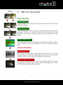
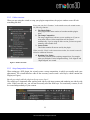
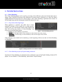
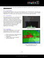
SSX3.0 USER MANUAL (Do not print this page) Last Update: April 23, 2013 1 2013 © emotion3D. All rights reserved. SSX3.0 User manual Product Description The SSX is a suite of After Effects plugins for manipulating stereoscopic 3D (S3D) footage in post. It enables fixing of stereoscopic-3D (S3D) shots, e.g. re-aligning geometry, colour matching between two views or reducing excessive parallax burnt-in during filming. Independent convergence and parallax modification also allow footage to be adjusted to the depth budget of the intended viewing conditions. The sophisticated visualization tools included in the SSX facilitate these processes. The most common uses of the SSX are listed below: Colour matching automatically, providing a choice of which eye to match to. Expert tools support region-based matching (e.g. lens flares, reflection differences due to camera polarizations). Geometry alignment to automatically remove pan/tilt/roll, vertical misalignments, keystone and zoom mismatch between stereo cameras. Depth grading for smooth depth transitions at shot boundaries and tailoring the depth script to the narrative. Remastering S3D for different viewing conditions, e.g. converting from TV to mobile version. Converting S3D content to multiview formats for viewing on auto-stereoscopic displays. Depth Map generation and exporting for depth-based compositing and VFX work. (N.B. we use the terms “depth” and “disparity” interchangeably.) Depth LUT manipulation, giving artists the ability to change the depth of individual objects within a scene. 2D to 3D conversion from available left images + corresponding depth maps Quality Control monitoring and analysis of geometry and depth to meet broadcasters’ specifications. 2 2013 © emotion3D. All rights reserved. Contents 1 2 3 Technical Requirements ........................................................................................................................ 5 Installation ............................................................................................................................................. 5 Licensing ............................................................................................................................................... 5 3.1 Product Activation/License Retrieval ............................................................................................. 6 4 SSX 3.0 - Overview............................................................................................................................... 7 5 Workflow Essentials.............................................................................................................................. 9 5.1 Importing Content into After Effects .............................................................................................. 9 5.2 SSX Setup Wizard .......................................................................................................................... 9 5.2.1 The Wizard Interface ............................................................................................................... 9 5.2.2 Folder structure...................................................................................................................... 11 5.2.3 Setup Composition Structure................................................................................................. 11 5.3 Nested Composition Setup ........................................................................................................... 12 6 Detailed Instructions............................................................................................................................ 13 6.1 Colour Matching ........................................................................................................................... 13 6.1.1 Setup Colour Matching Plugin .............................................................................................. 13 6.1.2 Colour Matching as part of Depth Grading Advanced.......................................................... 13 6.2 Vertical Alignment ....................................................................................................................... 14 6.2.1 Scene Cut Setup..................................................................................................................... 14 6.2.2 Data Export............................................................................................................................ 14 6.3 Depth Grading Basic 3D ............................................................................................................... 15 6.3.1 Disparity Range Setup ........................................................................................................... 15 6.3.2 Left / Right Image Check ...................................................................................................... 16 6.3.3 Depth Visualizer .................................................................................................................... 17 6.3.4 External Display .................................................................................................................... 18 6.3.5 Depth Analysis ...................................................................................................................... 18 6.3.6 Depth Budget ......................................................................................................................... 18 6.4 Disparity Generator ...................................................................................................................... 19 6.4.1 Rendering Disparity .............................................................................................................. 19 6.4.2 Technical Information: the SSX Disparity Format ............................................................... 20 6.4.3 Transform Disparity with After Effects „Levels“ Filter ....................................................... 20 6.5 Depth Grading Advanced 3D ....................................................................................................... 21 6.5.1 Scene Adjustment Setup ........................................................................................................ 21 6.5.2 Disparity Manipulator ........................................................................................................... 22 6.5.3 Depth Transitions .................................................................................................................. 22 6.5.4 Output Mode.......................................................................................................................... 23 6.5.5 Rendering Multiview ............................................................................................................. 23 6.5.6 Expert Settings ...................................................................................................................... 23 6.5.7 Rendering .............................................................................................................................. 27 6.6 Depth Grading Advanced 2D ....................................................................................................... 27 3 2013 © emotion3D. All rights reserved. 6.7 Disparity Tools ............................................................................................................................. 28 6.7.1 Disparity Structure ................................................................................................................ 28 6.7.2 Disparity Smoothing.............................................................................................................. 28 6.7.3 Disparity Clipping ................................................................................................................. 28 6.8 Depth Map Correction Workflow ................................................................................................. 29 7 Troubleshooting................................................................................................................................... 30 8 Appendix A: 3rd Party Software .......................................................................................................... 32 4 2013 © emotion3D. All rights reserved. 1 Technical Requirements 1) Hardware a. PC with a minimum of 8 GB memory (recommended: 12+ GB). b. NVIDIA graphics card with 1+ GB memory and CUDA Compute Capability 1.2 support or above (see if your graphics card is supported at http://developer.nvidia.com/cuda-gpus). 2) Software a. Windows 7/Vista, 64-bit b. After Effects CS5, CS5.5 or CS6.0 c. NVIDIA drivers version 266.58 or above (Jan 18, 2011 and later) and supported by AE (see http://www.adobe.com/products/aftereffects/tech-specs.html). 2 Installation 1) Download SSX installer software via customer portal: http://www.emotion3d.tv/customers/login (Customer login required) 2) Start the installer and follow the instructions 3) Start After Effects. The SSX plugins will be available in the “emotion3D” > “SSX” sub-folder within your After Effects “Plug-ins” folder. 4) Set AE to 32 bit mode to exploit the full depth-accuracy of the SSX plugins. 3 Licensing Every time the plugin is used in AE, it is checked for a valid license. If the license is not available or expired, the user is prompted to activate/reactivate the product in order to retrieve a valid license. Note: Please check your PC’s date and clock settings before activation in order to avoid any licensing issues. 5 2013 © emotion3D. All rights reserved. Figure 1. Security Error on first use 3.1 Product Activation/License Retrieval The product activation process (license retrieval) uses emotion3D License Manager (Figure 2) to retrieve a license. It starts automatically while using the plugin without valid license or it can be run from Windows Context Menu at Programs → emotion3D → SSX [version] → emotion3D License Manager Figure 2. emotion3D License Manager The license manager displays product and license information, activation buttons and contact references. Please click on the “Contact Support” or “Contact Sales” links to report any difficulty experienced while activating or using the software. Proxy Server: If you are using a proxy server, you will have to enable the “Proxy Settings” (5) option and enter your connection settings. 6 2013 © emotion3D. All rights reserved. 4 SSX 3.0 - Overview Simple Workflow Colour Matching Colour Matching can be used for correcting colour differences between left and right camera images. Vertical Alignment Camera misalignments, such as camera roll, pan or tilt differences between two stereoscopic cameras, are among the most common stereoscopic issues and should be corrected prior to generating disparity maps or adjusting the depth budget. Depth Grading Basic 3D This plugin provides tools for analyzing your stereoscopic footage as well as tools for making simple depth adjustments which do not need any disparity maps. Advanced Workflow Disparity Generator The Disparity Generator plugin renders disparity maps from stereo content. Disparity maps are needed to perform depth correction on your stereoscopic content and will be needed in the Depth Grading Advanced plugins. Depth Grading Advanced 3D Use the SSX's depth adjustment features to stay within the comfort zone of your 3D displaying environment and to achieve optimal depth impression, with the ability to stretch, clamp and scale effortlessly. 7 2013 © emotion3D. All rights reserved. Conversion Workflow Depth Grading Advanced 2D The Depth Grading Advanced 2D plugin allows you to convert your 2D content into 3D content. All you need is a camera image and the corresponding disparity map. Once converted, you will be able to perform all of the SSX’s depth adjustments in this plugin alone. Disparity Correction Tools Disparity Smoothing The Disparity Smoothing filter helps you to control the edge sharpness versus smoothness of disparity maps. Applying this plugin to your disparity maps and optimizing the settings can improve subsequent the results of depth grading. Disparity Clipping In disparity map correction of disparity maps, it is often necessary to rotoscope some objects and modify the disparity values where certain areas of the object have not been assigned correctly. The Disparity Clipping tool helps you to assign a certain depth range to an object so that as much depth information as possible is preserved. Disparity Structure An effective way to correct edges of foreground objects that have been “cut-off” (e.g. hairy objects or semi-transparent regions between foreground and background) is to use the Disparity Structure plugin to dilate or erode your disparity maps. This tool is especially helpful when performing corrections on rendered disparity maps (e.g. when your rotoscoped region is not accurate enough). 8 2013 © emotion3D. All rights reserved. 5 Workflow Essentials 5.1 Importing Content into After Effects Before using the SSX plugins, video content has to be imported into After Effects (AE). The input will be stereoscopic content, unless using the “Depth Grading Advanced 2D” plugin. You can import your footage into AE by going to “File” > “Import” and choosing the preferred import option. Alternatively you can also drag and drop your content from windows explorer directly into AE’s project window. 5.2 SSX Setup Wizard A wizard helps to guide through the steps required in each plugin. To reveal the wizard, select the “SSXWizard_[version]” script from the After Effects “Window” dropdown menu and follow the instructions. 5.2.1 The Wizard Interface 1. Plugin Choose the plugin you would like to use. Based on your previous selection, the SSX-Wizard will suggest which plugin to use as next. 2. Source Settings Source Type: Choose the Source Type of your Footage. Depending on the plugin you’ve chosen, this can be: Separate (individual files) Side-by-Side Top-Bottom 3. Copy settings from You can copy your settings from any existing plugin composition. If you don’t want to copy any settings, select the unlabeled option. The checkboxes indicate which settings can be copied. If an option is disabled, then the setting cannot be copied by the script. [Note: Currently Disparity Manipulator keyframes cannot be copied by the script and therefore have to be copied manually] 4. Options Show all sources: the wizard hides some specific compositions that are created during the setup process. If you need to see all compositions, just enable this option. Figure 3. SSX Wizard: plugin selection 9 2013 © emotion3D. All rights reserved. Side-by-side content with the SSX Advanced Plugins Currently importing side-by-side video content into the “advanced” plugins is not possible. Alternatively you can use our SplitScript to convert your SBS content into two separate compositions. Therefore: 1. select your SBS content in the Project window 2. go to “File > Scripts > SplitScript.jsxbin” Now, two new compositions “Split Left” and “Split Right” have been created. When you have set up the plugin the instructions interface is shown, depending on which plugin you have chosen: 1. Reset You can reset the wizard at any time. This will bring you back to the initial screen. 2. Steps To get the best results using the SSX plugins, you should follow the recommended workflow steps listed in the Wizard. 3. Help When you move your mouse over areas showing a question mark, a help tip is shown with some extra information regarding the step. 4. Important Message Important message fields are displayed in red and should not be ignored. 5. Finish Settings When you’re done with all the steps, you can chose if you would like to continue by rendering the results, or just continue without rendering. When you click ‘Finish’, the setup will be finalized and the wizard will return to the initial screen. Figure 4. SSX Wizard: instructions Window Location We recommend putting the wizard next to the project window, so that you can always see what the wizard has done. It is also recommended to allow enough horizontal space so that no information is hidden. 10 2013 © emotion3D. All rights reserved. 5.2.2 Folder structure When you are using the wizard to setup your plugin compositions, the project window soon will look something like this: Every time you click “Continue” in the initial screen, the wizard creates the following elements: 1. The Plugin Folder Each plugin folder name consists of a number and the plugins name 2. The Setup Composition The setup composition is the one you are working on. If you are using After Effects 6.0 the composition will be opened automatically, if you’re using an older version, you have to open it manually with a double click. 3. Source Folder This folder contains all sources used by the plugin When you click ‘Finish’ in the instructions window, the wizard creates the following additional elements: 4. Resulting View Folder This Folder contains all the resulting compositions. For example: when you finish the Vertical Alignment Setup, “Left Aligned” and “Right Aligned” are created. Figure 5. Folder Structure 5.2.3 Setup Composition Structure When setting up a SSX plugin, the wizard creates a setup composition, in which you usually make your adjustments. The wizard therefore adds all the necessary sources and a solid layer, which contains the Plugin (see Figure). But why not simply add the plugin to the top source layer? The solid layer is important when working with side-by-side input content and rendering out side-by-side video. If that’s not the case, you will not necessarily need the solid layer. For consistency reasons, it will be created independently of your content. Figure 6. Composition Structure 11 2013 © emotion3D. All rights reserved. 5.3 Nested Composition Setup The SSX workflow usually requires the use of multiple plugins. For example you start with Colour Matching then directly continue with the Vertical Alignment and then set up the Disparity Generator plugin with the resulting compositions. Often, you would like to perform all these steps without rendering out your video material. We call this a nested composition setup. Unfortunately, nested compositions have drawbacks: When setting up nested compositions, every plugin has to check out the frames from the preceding plugin, which can slow down the project, especially when using multiple compositions in a row. When using the resulting views of the Disparity Generator as input for the Advanced plugins, additional memory needs to be allocated, which leads to a very high memory consumption. To overcome these drawbacks we generally recommend rendering the intermediate results before continuing with another plugin (especially after Disparity Generation). 12 2013 © emotion3D. All rights reserved. 6 Detailed Instructions 6.1 Colour Matching The Colour Matching plugin can be used for correcting colour differences between left and right camera images. Due to physical occurrences like differences in camera lenses, reflections, etc., there are almost (slight) differences between the two camera images. After colour matching is performed, the colours of left and right image and their histograms should look almost the same. 6.1.1 Setup Colour Matching Plugin When applied to a sequence, the whole clip is colour matched by default. If you would like to colour match a certain scene, go to the desired location in the timeline and then click on the stop watch at “Colour Matching” and select one of the following options: Figure 7. Colour Matching Interface Disable: No colour matching is performed Match Left: The right image is colour matched, so that it fits the left colour scheme. Match Right: The left image is colour matched, so that it fits the right colour scheme. If the following scene should not be matched, go to the beginning of this scene and set Colour Matching to “Disabled”. Figure 8. Setting keyframes in After Effects Timeline 6.1.2 Colour Matching as part of Depth Grading Advanced If preferred, Colour Matching can alternatively be performed as part of the Depth Grading Advanced 3D plugin. You can find the “Colour Matching” option under “Expert Settings”. 13 2013 © emotion3D. All rights reserved. 6.2 Vertical Alignment The Vertical Alignment plugin can be used for correcting vertical misalignments as well as pan/tilt/roll and keystone effects between the left and right camera images. After the correction, each point in the left image is located on the same horizontal line as the corresponding point in the right image. Vertical alignment of the images is normally done as a second step and will improve the results of the depth map generation and any further depth-based processing. 6.2.1 Scene Cut Setup The whole clip in the composition needs to be split into individual shots/scenes. We recommend working on one shot at a time as the software is designed to take all the frames of the shot into consideration; this is particularly important to get the best, correct results in the final rendered output. In the SSX for After Effects, Shot Boundaries are keyframes of the Layer, on which the SSX plugin is Figure 9. Automatic Scene Setup applied. The SSX automatically detects the boundaries and sets the keyframes if the following steps are followed: a) Select the Work Area in the Timeline panel. Shots will only be detected using range of the frames within the Work Area. NOTE: All Shots overlapping with Work Area will be affected. b) Select “Automatic” Scene Setup mode. c) Click Process (under the “Setup Work Area” dropdown) to generate shot/scene cut Boundaries. d) Once the keyframes have been placed, review their positions manually in the viewing window and remove any redundant keyframes. You may create, move or delete existing keyframes in case the real shot cuts differ from the detected ones. 6.2.2 Data Export On pressing the ‘Process’ button in the Setup Work Area section, the Vertical Alignment plugin analyses the footage within the work area regarding scene cuts, minimal and maximal disparities and geometric alignment differences between left and right camera views such as rotational, vertical and zoom offsets. After the analysis step has been finished, the summarized results of this analysis can be exported and used for quality control of your stereo footage. The data can be exported into a .csv file via the ‘Export’ button in the ‘Export Data’ section and viewed in any text editor or program with .csv import support such as Microsoft Excel. 14 2013 © emotion3D. All rights reserved. 6.3 Depth Grading Basic 3D This plugin allows you to perform simple Depth Grading tasks and provides powerful tools for analyzing your stereo content. 6.3.1 Disparity Range Setup For disparity analysis you will first need to setup the disparity range for every shot of the original content with the correct min/max parallax, which correspond to the nearest and furthest objects in the scene. In SSX for AE, this depth information is stored as keyframes for foreground and background disparity parameters. These values can be set automatically by clicking the “Process” button under the “Setup Work Area” heading. Review the depth maps in each shot and manually correct any incorrect range settings, as described below (or they may already be imported by the SSX-Wizard. Manual Scene Setup a) In the timeline go to a frame with either closest foreground or furthest background objects (corresponding to extremities in the parallax) within the shot you want to work on. Make sure the “Preview Popup” box is ticked. b) Drag the "Background Disparity" slider. This brings up a window with the left & right images superimposed (see Figure). As you slide the mouse to the side, the images move relative to each other. Find the position where the background objects appear to be aligned (it’s safer to overshoot to the right rather than undershoot). The resulting value indicates the maximum positive parallax in the shot. c) Repeat the step above for the "Foreground Disparity". This time align the foreground objects. The resulting value indicates the maximum negative parallax in the shot. d) Look at the Disparity Preview parameter window, which shows a small depth map automatically generated by the software. Objects closer to the cameras should appear brighter than those far away. Readjust the sliders if necessary to obtain a grayscale image that corresponds to the distances in the scene. e) Repeat this process for other frames to check that the foreground/background extremes within the shot have been covered. Apply the largest values in each case to the keyframe at the start of the shot and remove any other keyframes within the shot that were introduced during this process. Figure 10. Manual Disparity Range Popup Overlay 15 2013 © emotion3D. All rights reserved. 6.3.2 Left / Right Image Check There is always the danger that the image sources may be flipped (left = right, right = left). In general flipped input sources can be detected in either of the following ways: (i) (ii) Checking the Depth Map Preview: white represents close objects, dark represents more distant objects and this guarantees (i) that left image really represents the left image and right image and (ii) that the background (BG) disparity is larger than the foreground (FG) disparity. This should always be the case. If it appears the other way round (close regions are dark), the images are flipped and the “Left/Right Source” dropdown selections should be swapped. In the Preview Popup mode: after aligning the Background, the Foreground Disparity slider does not allow the images to move in the correct direction and align the foreground. Figure 11. Depth Map Preview 16 2013 © emotion3D. All rights reserved. 6.3.3 Depth Visualizer Figure 12. Depth Visualizer The Depth Visualizer provides various controls to pre-visualize the depth impression on a target display. A target display can be defined by its screen size, distance from viewer to screen and the interocular distance between the viewer’s left and right eyes. These settings can be defined either directly via the individual controls or indirectly by choosing a displaying environment preset via the Environment selection. For visualizing markers for the screen plane and the disparity limits within the 3D Visualizer, the checkbox “Markers” must be enabled. Alternatively, a depth colourization of the scene can be achieved by enabling Depth Colouring. Apart from the 3D representation, the amount of your scene that is inside/outside your target display’s comfort zone is displayed at the bottom of the control window. Navigation within the Visualizer: Use left and right mouse button to rotate and move your 3D scene and the middle button to get distance information for individual points. Scrolling via the middle mouse wheel enables zooms in/out. 17 2013 © emotion3D. All rights reserved. Export 3D screen to file: Click on the export button in the top menu to export a .bmp / .jpg image of your current 3D scene. 6.3.4 External Display For displaying your content in 3D on an external 3D display: select “External Preview” and choose the appropriate output options. The 3D mode on the monitor must be set to match the selected "External Output Mode” (e.g. Side-by-side). N.B. External Preview slows down the plugin significantly. 6.3.5 Depth Analysis The depth characteristics of the current frame are illustrated in histogram form under the Depth Analysis tab. The green vertical line depicts the screen plane, i.e. point of zero parallax. The red and blue vertical lines mark the user-defined background and foreground disparity values set in the Max/Min Disparity Limit section above. N.B. changing these values only modifies the appearance of the histogram and does not affect the depth characteristics of the footage. 6.3.6 Depth Budget Enable “Show Depth Budget” to view a colourcoded impression of the scene relative to the Min/Max Disparity Limit positions set above: Figure 13. Depth Analysis RED: too much positive depth (background) BLUE: too much negative depth (foreground) GREEN: indicates regions within the specified comfort zone Figure 14. Depth Budget Preview (blue indicates too close; red too far) 18 2013 © emotion3D. All rights reserved. 6.4 Disparity Generator The Disparity Map Generator renders depth maps from stereo content. The input to this plugin is always a left and right input stream. Note that it is recommended to use the Vertical Alignment plugin before the Depth Generator plugin since this can significantly improve the quality of the resulting depth maps. 6.4.1 Rendering Disparity Depth maps can be exported via rendering for further processing in many other software programs (e.g. Photoshop, 3DS Max). The most common use is in conjunction with compositing and VFX tools, such as Autodesk Smoke and Nuke. Alternatively the depth maps can be modified in After Effects or other software and re-imported into the SSX plugin for rendering (see following sections). Common modifications include: (i) manual improvement of the depth maps with edge correction, sharpening or softening; (ii) re-colouring the depth map for artistic 3D effect, such as moving individual objects or regions forward or backwards in relation to the rest of the scene. N.B. modified depth maps should only be imported into the SSX in the “Depth Grading Advanced 2D” mode, because the correspondence between original left and right images is no longer represented by the modified depth map. When rendering multiple times from the same source images (e.g. with multiple parameter settings), speed improvements can be achieved if the depth maps are rendered once (as this is a relatively slow process) then re-imported and used multiple times in separate compositions that can be added to the render queue. As the depth maps have not been modified in this case, the “Depth Grading Advanced 3D” mode is recommended. To render a sequence of Depth Maps: i) Select “Left Depth” or “Right Depth” from the Output Mode dropdown menu. ii) Set the output format within the render settings (“Output Module”) of the depth maps to a 32-bit floating point precision format such as OpenEXR (N.B. store uncompressed, e.g. with Zip16). Note that the left and right depth maps are different and correspond to the depths in the left and right source material, respectively. 19 2013 © emotion3D. All rights reserved. 6.4.2 Technical Information: the SSX Disparity Format Disparities generated by SSX are relative disparities. The disparity range values [-10%, 10%] are mapped to [0, 1] when exporting OpenEXR files, i.e.: "-10%" is mapped to "0", "0%" is mapped to "0.5" and "+10%" is mapped to "1". Disparities outside this range are also mapped correctly, but cannot be seen when watching the disparity map. In addition, SSX inverts the relative disparities of the "left" disparity image before a mapping to [0, 1] is performed (for inverting back, use the After Effects “Invert” effect). 6.4.3 Transform Disparity with After Effects „Levels“ Filter Depth maps calculated by SSX usually do not use the whole image range, but just a part of it, because with 32 bit unlimited depth levels are possible within this range. Since some tools require 8 bit maps and therefore are limited in depth levels (255) it you may want to convert those disparity maps to the whole image range before converting them to 8 bit, so that as less depth information as possible is lost. For this purpose, we recommend using the After Effects “Levels” filter. Short Explanation: For every scene you will have to adjust the “black” and “white” values so that the histogram fits into this border. Leaving some buffer is recommended, since most scenes are likely to change slightly from frame to frame, otherwise some depth precision is lost. 20 2013 © emotion3D. All rights reserved. 6.5 Depth Grading Advanced 3D Use the controls in the Scene Adjustment group to modify the volume and position of your content in 3Dspace. This plugin requires as input the source footage plus corresponding left and right depth maps (as rendered by the Disparity Generator plugin). The configuration is depicted in Figure 15. N.B. The left and right disparities have to be consistent for correct results. Figure 15. Rendering from Stereo3D + Z 6.5.1 Scene Adjustment Setup Goal: Modify the parallax of the content to fit the desired depth budget. The plugin creates 2 virtual cameras from the input left/right images, whose parallax can be adjusted via the controls and visualized in several ways. (N.B. this is not a simple H.I.T!) Steps: a) Specify under “Min Disparity” and “Max Disparity” the disparity limits for your target display (e.g. Sky TV’s budget is between -1% and +2%). b) Look at the parallax visualization tools and move the sliders “Convergence Shift”, “Disparity Scale” and “Zoom” to fit your depth budget specified in the previous step. c) View the results: i) in 3D on an external 3D display (select “External Preview” and choose the appropriate option). The 3D mode on the monitor must be set to match the selected "External Output Mode” (e.g. Side-by-side). N.B. External Preview slows down the plugin significantly. ii) in 2D (e.g. side-by-side, delta anaglyph etc) – either on the working monitor (depending on the Output Mode) or on an external 2D monitor or TV (depending on External Preview settings). Other controls: - Disable Camera Fusion: use a different method for generating the new camera perspectives; use this if the image rectification is imperfect, or if there are colour difference between the original left and right cameras. - Zoom: the edges of the generated new camera views sometimes show artifacts or distortions, which can easily be removed by zooming-in the final composition. This zooming is done in the center of the frame. If you would like to see a specific part of the zoomed image, you can set the “Translation X” and “Translation Y” sliders. 21 2013 © emotion3D. All rights reserved. 6.5.2 Disparity Manipulator This tool helps you to easily stretch and compress certain disparity ranges. In contrast to complicated lookup tables, this tool allows powerful depth manipulations based on the disparity histogram directly. A common use case is changing the disparity scale for positive or negative disparities only. Figure 16. Disparity Manipulation 1. At the top of the histogram a yellow line can be seen. This yellow line indicates that the disparity has the original scale. 2. Click on the line to create a new keypoint. The numbers beneath the keypoint are showing the scaling factor between the keypoint and its left / right neighbors. 3. Hold the mouse button and move to another position. The scaling factor as well as the line colour are changed according to the direction you are moving: red indicates that the scaling factor is less than 1.0, i.e. the region is being compressed. blue indicates that scaling greater than 1.0, i.e. the region is being stretched. 4. After releasing the mouse button, the keypoint will be activated in the new position. In general, the Disparity Manipulator allows the following interactions: Insert a new keypoint by clicking into the grey area at the top of the histogram Change the position of an existing keypoint by simply dragging it See the current scaling factor by clicking on a keypoint and by not releasing the mouse button Delete a keypoint by dragging it over the top border of the histogram Interpolation between keyframes: Since scenes will often contain movement, it is important to interpolate disparity manipulations within a scene. Therefore the manipulations will be interpolated linearly between every created keyframe. Nevertheless interpolation can also be deactivated by setting keyframes to “hold”. 6.5.3 Depth Transitions This feature facilitates smooth handovers in depth between one shot and the next. Simply move the time cursor to the first scene of the incoming shot and the handover frames 22 Figure 17. Selecting Point of Interest in the Depth Transition Window 2013 © emotion3D. All rights reserved. will appear in the window. Click on the Point of Interest (POI) in the outgoing shot (top) and then the POI in the incoming (bottom) shot. This will apply a Horizontal Image Translation (HIT) to the first frame of the incoming shot so that its POI is at the same position in depth as the outgoing POI. By default this HIT is gradually relaxed over the first 5 frames of the incoming shot, but this can be modified in the timeline by moving the Convergence Shift keyframes appropriately. Figure 18. Convergence Shift Applied to Incoming Shot 6.5.4 Output Mode Numerous Output Modes are supported, such as side-by-side, top-bottom, crosseye, multiview (see below), etc. The selected choice is visible in the AE composition panel and also used for rendering. 6.5.5 Rendering Multiview Multiview mode is used to render additional camera views for autostereoscopic displays that require more than two views. In order to obtain all the views it is necessary to render multiple times with different output camera view numbers. a) In Output Mode parameter select “Multiview” b) Open View Adjustment group; a new section Figure 19. Multiview Settings “Multiview” appears c) Set Number Of Cameras (8 by default) slider d) Drag Camera ID slider to preview each camera position. e) (optionally) Adjust Camera Position for finer virtual camera control. 6.5.6 Expert Settings A number of additional controls are provided for finetuning the results of the depth map and new perspective generation algorithms. 23 Figure 20. Expert Settings 2013 © emotion3D. All rights reserved. Clicking Disable Fusion is recommended if there is considerable colour or lens distortion mismatch between cameras. The other controls are described in the following sections. 6.5.6.1 Colour Matching Equal to the stand-alone Color Matching plugin, this feature enables global color matching between left and right image. The colour matching takes place before a new perspective is generated and performs a global histogram matching between both views. Option: Match left: The colour histogram of the right image are matched to fit the color histograms of the left image. Match right: The colour histogram of the left image are matched to fit the color histograms of the right image. Note: It is recommended to perform colour matching as a separate pre-processing stage using the Colour Matching plugin. 6.5.6.2 Fusion When working with stereo footage, information from left and right view can be exploited for generating a new perspective. This feature allows you to prefer a certain source for the creation of the resulting views. This is especially useful, when your video material contains disturbing artifacts (like lens flare) or blurred objects in just one camera image or when your camera images contain local colour differences which cannot be matched by a global colour matcher. Off: Automatic: On: 6.5.6.3 Disable fusion in case the new perspective shall only be created based on one source view. See 6.5.6.3 Preferred Source for source view selection. Fusion is only used for creating internal perspective (0% - 100% Disparity Scale). Fusion is always enabled. In contrast to Automatic, also external perspectives are created based on both input views. Preferred Source One of the following options can be chosen: Prefer Closest (default): Prefer Left: Prefer Right: This mode will always pick the spatial closest pixel for the creation of the resulting view. This typically is the recommended setup if fusion is enabled. The resulting view is mainly composed of pixels of the left image, only areas which cannot be filled with the information of the left image will contain pixels of the right image. The resulting view is mainly composed of pixels of the right image. For setting this feature to “Prefer Left” or “Prefer Right” it is very important, that the disparity maps between the images match. Otherwise visual artifacts may occur in the resulting views due to fusion. 24 2013 © emotion3D. All rights reserved. 6.5.6.4 Fill In Holes In case no information is available for generating a region in a new perspective (e.g. disoccluded regions that are not available in both source camera views), an inpainting algorithm aims to fill in missing holes. Disable: Disables infilling of missing regions. Use this feature in case you want to fill in the missing regions yourself using for example Adobe Photoshop’s context-aware region filling. Occlusions: Only holes that were generated by disoccluding regions in the source camera images are filled. This is the recommended setup for most use cases such as parallax adjustment or generation of stereo perspectives from 2D footage. Occlusions+Alpha: Fill all disoccluded regions and also all pixel regions with alpha values smaller/equal 0.0. This option can be used in combination with 6.5.6.5 Clipping of small regions. 6.5.6.5 Clipping Function The Clipping Function uses the depth map information to selectively hide regions from the foreground and/or background: move the Foreground Clipping value closer to zero in order to increasingly hide the foreground; conversely, move the Background Clipping value closer to zero in order to increasingly hide parts of the background. Figure 21. Clipping Function Isolating Foreground 25 2013 © emotion3D. All rights reserved. 6.5.6.6 Dilation Figure 22. Dilation Applied to Clipped Image An effective way to correct edges of foreground objects that have been “cut-off” (e.g. hairy objects or semi-transparent regions between foreground and background) is dilation of the depth maps. The SSX provides dilation sliders in the expert settings for extending the objects in the depth map horizontally (X) or vertically (Y). For example, if a part of a foreground object in the depth map is wrongly labeled as background than this part would be cut off in the virtual perspective views. For example, in Figure 23, the right part of the roof is wrongly labeled as background and therefore cut-off. By increasing the horizontal dilation from 0 to 6 we extend the foreground object in the depth map. In the novel view this removes the cut-off region. (a) Dilation X = 0 (b) Dilation X = 3 Figure 23. Dilation for correcting foreground object edges. 26 2013 © emotion3D. All rights reserved. (c) Dilation X = 6 6.5.7 Rendering If you use the Wizard for setting up your projects, this will automatically add appropriate compositions to the render queue if you allow it. Alternatively you may set up renders manually as follows: Verify that the “Output mode” is set to your desired format (side-by-side, top-bottom etc). Switch off “Show Depth Budget”. Add the composition to the render queue. In the “Render Queue” tab, review the output filenames and location Click the setting in the ‘Output Module’ and change the Format in the pop-up window to OpenEXR. Click on ‘Format Options’ and check the ’32-float’ box. Select a non-lossy compression format such as Zip16. f) Then click render to generate a video sequence (Figure 24). (N.B. the first image in a sequence always takes longer to render than the remaining ones.) a) b) c) d) e) Figure 24. Render Queue 6.6 Depth Grading Advanced 2D This mode allows rendering of 2 or more views from a single view plus depth maps. This is particularly useful in 2D-to-3D conversions for automating the generation of new camera perspectives where depth maps have been created for each frame by a rotoscope/paint team. This contains the same controls as the Depth Grading Advanced 3D plugin. Figure 25. Converting 2D to 3D content 27 2013 © emotion3D. All rights reserved. 6.7 Disparity Tools 6.7.1 Disparity Structure This tool allows you to Dilate (Extend Foreground), or Erode (Extend Background) your disparity maps. The advantages of dilation have already been highlighted in Chapter 6.5.6.6 - Dilation. With this tool it is possible to dilate/erode the whole disparity map, or to dilate/erode previously selected sub regions of an image, which is useful for disparity map correction (see chapter Dilation 6.5.6.6 for further explanation). 6.7.2 Disparity Smoothing The Disparity Smoothing plugin helps to achieve smoother and structure-aware disparity maps, based on the corresponding colour images. The disparity smoothing filter is assigned to the depth map composition and needs the definition of the guidance images. By moving the “Radius” slider you can control the amount of spatial information that is taken for smoothing. The “Threshold” slider controls the ratio between noise and blurriness. 6.7.3 Disparity Clipping When correcting rendered disparity maps, it is often necessary to rotoscope some objects and assigning new pixel gray values where the automatically-generated values do not produce optimal results in the final colour image renderings. The Disparity Clipping tool helps you assigning a certain depth to an object without losing its depth structure. Therefore choose the minimal allowed value (background) and the maximal value (foreground) by choosing the colours in a colour-picker window, or by selecting the colour directly by clicking into the image using the eyedropper tool. You can also use the “Tolerance” slider to relax your colour selection. Figure 26. Disparity Clipping Interpolation: By default, the min and max values are interpolated linearly between multiple keyframes. If you don’t want them to interpolate, set the keyframes to “hold”. Select a colour by clicking into the image itself. Figure 27. The eyedropper tool in AE. 28 2013 © emotion3D. All rights reserved. 6.8 Depth Map Correction Workflow This section describes the disparity map correction possibilities of the SSX plugins and suggests a way to perform disparity map correction on stereo content. If the results you’ve received during Depth Grading Advanced are not accurate enough you will have to perform manual corrections on the disparity maps. At this point After Effects in combination with the SSX Disparity Tools can be a powerful tool to achieve better results. Now, we are presenting a sample workflow, which shows you how disparity map correction with SSX Disparity Tools could look like. In the following, it is assumed, that you’ve already rendered your disparity maps. 1. First of all open your depth maps. 2. To see how your changes affect the result, we recommend setting up the Depth Grading Advanced 3D Plugin as the next step. Please, configure your plugin as follows: Go to Expert Settings and set Preferred Source to Prefer Left. This will save you considerable effort, since you will mostly have to correct the left disparity map only. When now working on your disparity maps you will be able to immediately see the impact of your changes. 3. Now, try to achieve better results by using the Disparity Smoothing plugin. Experimenting with the slider values may increase the visual quality of the results. 4. Assign the Disparity Structure plugin on the disparity map and experiment with the dilation slider. If you see no improvement, remove it. 5. Artifacts on objects must be corrected; the easiest way is to use AE’s rotoscoping functionality: a. Take the original colour image and mark the desired object with the Roto Brush Tool. b. When finished, click “Freeze” to fix your selection. c. Now duplicate your disparity layer d. Copy the frozen Roto Brush to it. 6. Now use the clipping tool and assign min / max values. Sometimes you will have to perform steps 3 – 7 multiple times on different objects until the result looks like desired. 29 2013 © emotion3D. All rights reserved. 7 Troubleshooting The Foreground/Background Sliders are “locked” and won’t let me align the Images The left/right cameras are swapped. Reselect the Left and Right sources the other way around. Visual Artifacts Here are some techniques to reduce these: - Keep baseline adjustments small, and ideally reductions rather than increases. This translates to keeping “Disparity Scale” at 100% or less. N.B. You can also use “Zoom” to effect a baseline increase. - Run the source footage through the Vertical Alignment plugin before other plugins. - Avoid strong colour differences between the two cameras (or colour match first). - Try selecting/deselecting “Disable Camera Fusion”. - Setting up the Disparity Range manually. Look carefully at the depth map and aim for an image that corresponds to your perception of depth within the scene, with closer objects appearing brighter than more distant objects. (It’s safer to set the disparity range too large than too small.) - Experiment with the Dilation sliders under Expert Settings. The edges of the images are missing or not clean This is because some information is missing from the scene. Use the Zoom slider to move these edges outside the viewable range of the frame. Slow Performance Check that a CUDA-compatible graphics card is available and the appropriate drivers are installed. External Preview External Preview functionality currently only works properly when used as a single window on a separate screen display (e.g. on a second 3d-capable monitor). It is intended for real-time preview of the generated views. If you put other windows on top of it on a single monitor it may not redraw – if so, navigate back to AE main window (Alt-Tab) and refresh it. Error message “OpenCL not available” This may appear when the plugin is applied to a layer. CUDA support has not been found and consequently the rendering takes very long. Make sure that appropriate CUDA drivers are installed. http://www.nvidia.com/Download/index.aspx Error message „invalid Filter“ Symptoms: An "invalid effect" error pop-up shows up in After Effects when applying a plugin to a composition/layer. Cause: This problem occurs in case of a missing .dll library file. Possible solutions: 30 2013 © emotion3D. All rights reserved. 1) If the error only shows up for the "Vertical Alignment" plugin but not for the other plugins, "C:\windows\system32\opencl.dll" is probably missing. This library typically comes with your graphics card drivers and for solving this issue, install the latest version of your graphics card driver on your system. Please make sure the newest graphics card drivers are installed and your graphics card fits the SSX requirements. 2) Please assure you (i) have Admin rights when installing the SSX - so all .dll files can be copied to your system directories and (ii) use "setup.exe" for installing the SSX. Using the .msi file will install the plugin, but not install C-runtime. After Effects runs out of memory when trying to render When rendering with high resolution footage, like 4K content (ultra HD), the memory consumption of the SSX plugins can get very high. Make sure you have enough memory installed. For minimal memory requirements see Section 1- Technical Requirements. For other questions contact: [email protected] 31 2013 © emotion3D. All rights reserved. 8 Appendix A: 3rd Party Software The SSX uses the following 3rd party software libraries and their licenses: Name Description License Boost Templates Boost Software License - Version 1.0 - August 17th, 2003 Permission is hereby granted, free of charge, to any person or organization obtaining a copy of the software and accompanying documentation covered by this license (the "Software") to use, reproduce, display, distribute, execute, and transmit the Software, and to prepare derivative works of the Software, and to permit third-parties to whom the Software is furnished to do so, all subject to the following: The copyright notices in the Software and this entire statement, including the above license grant, this restriction and the following disclaimer, must be included in all copies of the Software, in whole or in part, and all derivative works of the Software, unless such copies or derivative works are solely in the form of machine-executable object code generated by a source language processor. THE SOFTWARE IS PROVIDED "AS IS", WITHOUT WARRANTY OF ANY KIND, EXPRESS OR IMPLIED, INCLUDING BUT NOT LIMITED TO THE WARRANTIES OF MERCHANTABILITY, FITNESS FOR A PARTICULAR PURPOSE, TITLE AND NONINFRINGEMENT. IN NO EVENT SHALL THE COPYRIGHT HOLDERS OR ANYONE DISTRIBUTING THE SOFTWARE BE LIABLE FOR ANY DAMAGES OR OTHER LIABILITY, WHETHER IN CONTRACT, TORT OR OTHERWISE, ARISING FROM, OUT OF OR IN CONNECTION WITH THE SOFTWARE OR THE USE OR OTHER DEALINGS IN THE SOFTWARE. OpenCV Computer vision License Agreement For Open Source Computer Vision Library Copyright (C) 2000-2008, Intel Corporation, all rights reserved. Copyright (C) 2008-2010, Willow Garage Inc., all rights reserved. Third party copyrights are property of their respective owners. Redistribution and use in source and binary forms, with or without modification, are permitted provided that the following conditions are met: * Redistribution's of source code must retain the above copyright notice, this list of conditions and the following disclaimer. * Redistribution's in binary form must reproduce the above copyright notice, this list of conditions and the following disclaimer in the documentation and/or other materials provided with the distribution. * The name of the copyright holders may not be used to endorse or promote products derived from this software without specific prior written permission. This software is provided by the copyright holders and contributors "as is" and any express or implied warranties, including, but not limited to, the implied warranties of merchantability and fitness for a particular purpose are disclaimed. In no event shall the Intel Corporation or contributors be liable for any direct, indirect, incidental, special, exemplary, or consequential damages (including, but not limited to, procurement of substitute goods or services; loss of use, data, or profits; or business interruption) however caused and on any theory of liability, whether in contract, strict liability, or tort (including negligence or otherwise) arising in any way out of the use of this software, even if advised of the possibility of such damage. 32 2013 © emotion3D. All rights reserved.