1
PANIC
PRELIMINARY DESIGN REPORT
Code:
Iss/Rv:
Date:
Page:
PANIC-GEN-SP-01
0/1
22 October 2007
124 of 183
3.4.1.3.4 BP6 - 6 slot backplane
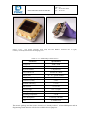
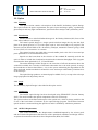
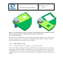
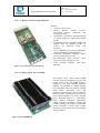
The BP6 connects the above three boards. There are 4 slots for AD36 boards, 1 slot for 1
ROCon and 1 for the H2RG_CB board. The backplane also connects to the power supplies and
delivers the power to the different boards.
The BP6 is layouted impedance controlled and has termination circuitry onboard. This provides
optimum signal integrity for high speed signals.
3.4.1.3.5 OPTPCI - fiberlink interface
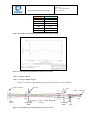
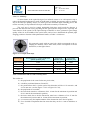
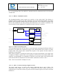
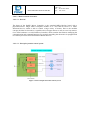
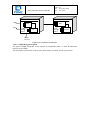
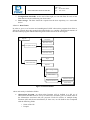
The OPTPCI board receives the data sent by the ROCon. Receiver 1 and 2 parallelizes the data
stream and writes it to the corresponding FIFOs. If an adjustable threshold is reached a DMA
request is produced and the data is written to the memory of the PANIC workstation.
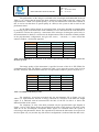
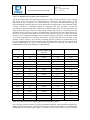
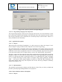
OPTPCI
Fiber 1
Receiver 1
FIFO 1
Fiber 2
Receiver 2
FIFO 2
FPGA
PLX9656
PCI 64 bit @ 66MHz
Figure 3.4.1-5 OPTPCI block diagram
The OPTPCI should be installed in a PCI slot with 64 bits @ 66MHz to reach the maximum
data rate of approximately 250 Mbytes per second. However the OPTPCI can be run in a PCI
slot with 32 bits @ 33 MHz. This will reduce the achievable data rate to approximately 100
Mbytes per second.