1
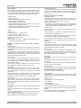
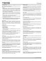
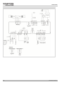
®
flexotron 800
PDS 46.300
flexotron®800
en product data sheet
flexotron®800: Electronic ventilation, air-conditioning and heating controller
Areas of use
Used universally in ventilation, air-conditioning and heating systems, or in similar applications
Features
•
•
•
•
•
•
•
Configurable controllers for a wide range of applications for ventilation, air-conditioning and heating
Many functions for sequences and monitoring
Clear operation due to large, illuminated LCD and buttons
Menus in 20 languages
Weekly and calendar switching programmes with summertime/wintertime change-over
Configuration using display or PC tool
RS485 interfaces with Modbus or TCP/IP and integrated Web server
Product
Type
Description
RDT808F211
Universal controller, 24 V~, 8 inputs/outputs, with LCD, with Modbus
RDT815F011
Universal controller, 24 V~, 15 inputs/outputs, without LCD, with Modbus
RDT815F211
Universal controller, 24 V~, 15 inputs/outputs, with LCD, with Modbus
RDT815F221
Universal controller, 24 V~, 15 inputs/outputs, with LCD, with integrated Web server
RDT828F011
Universal controller, 24 V~, 28 inputs/outputs, without LCD, with Modbus
RDT828F211
Universal controller, 24 V~, 28 inputs/outputs, with LCD, with Modbus
RDT828F221
Universal controller, 24 V~, 28 inputs/outputs, with LCD, with integrated Web server
Technical data
Power supply
Power supply
24 V~, ±15%, 50...60 Hz
21…36 V=
Approx. 9.8 VA, 3.5 W
Approx. 11.5 VA, 4.2 W Web models
Inputs and outputs
Universal inputs
Digital inputs
Analogue inputs
Analogue outputs
Start-up current
20 A (2 ms)
Digital outputs
Parameters
Control characteristics
P-band Xp
Integral action time
P, P/PI
0...300 K
0…600 s
Structural design
Dimensions W x H x D
Screw terminals
Dissipated power
Setting and measuring ranges
Fitting
Measuring range for normal tempera- -50...115 °C
ture
Reduced temperature
-50...115 °C
Setpoint and actual value auxiliary -50...115 °C
controller
Humidity
0...100% rh
Pressure sensor
-500...5000 Pa
CO2
0...5000 ppm
Ambient conditions
Admissible ambient temperature
Storage and transport temperature
Admissible ambient humidity
www.sauter-controls.com
0…50 °C
-20…70 °C
5…95% rh
No condensation
Standards and directives
Type of protection
Ni1000 (DIN 43760)
Potential-free contacts
Ni 1000, 0…10V
0...10 V, 2 mA, protected against
short circuit
Mosfet each 2 A, 24 V~/V=, not
protected against short circuit, max.
8 A total
148 × 123 × 60 mm (with terminal)
Pluggable terminals, for connecting
cables
2
up to 1.5 mm
Top-hat rail, switch panel (with accessories)
IP 20
(when installed)
CE conformity as per
EMC Directive 2004/108/EC
EN 61000-6-1, EN 61000-6-3
Additional information
Fitting instructions
Declaration of materials used
Wiring diagram
Dimension drawing
Ventilation user manual
Ventilation short manual
Modbus variables for ventilation
Heating user manual
Heating short manual
Modbus variables for heating
User manual for CASE flexotron®
P100011437
MD 46.300
A10707, A10708, A10709
M11510
P100012082
P100012091
P100012094
P100013115
P100013121
P100013118
P100012097
1/14
flexotron®800
Accessories
Type
Description
XYE460F002
Demo case for flexotron®800
0460240001
Pluggable terminal strips for flexotron®400/800
0460240011
Cabinet fitting kit for flexotron®800
RDB800F001
Operating unit for RDT800 (11.5 × 9.5 cm)
EGT338F102
External setpoint adjuster, room operating unit with potentiometer
Abbreviations/symbols
Configuration and parameterisation
The configuration and parameterisation of devices is performed via
the integrated display and the buttons, or via a separate module
that contains the same display and operating elements as the
device.
• SAV: supply air ventilator
• RAV: return air ventilator
• HW: Domestic hot water
Definition
The flexotron®800 devices are digital controllers for the airconditioning, heating and boiler control in building automation. The
controllers are freely configurable - the configuration and parameterisation are easily performed using the integrated display with 20
languages, a separate display, or a configuration tool.
The controllers are available as models with or without a display,
and depending on the model they can be used in networks by
means of a Modbus or using the integrated Web server. For controllers without an integrated display, a separate display can be
connected.
The flexotron®800 controllers are equipped with 8, 15 or 28 inputs
and outputs in order to meet the widest range of requirements.
Engineering notes
3-point activation of the valves:
• With 24 V= power supply for the controllers, the closing/opening
commands are passed on to the actuators via coupling relays.
• For actuators and devices with 24 V~, the LS terminal (24V) of
the RDT is connected to the MM terminal (ground in SAUTER
devices) of the actuators. If additional components are connected in the system, you must be sure to avoid ground faults. If required, coupling relays are used to activate the actuators.
0...10 V sensor signals on the analogue inputs for controlling CO2
and pressure must not fall below –0.5 V or exceed 10.5 V, as
otherwise the control function is stopped.
The voltage of +24 V at the terminal may only be used for controlling the digital inputs.
The ground wiring for the analogue inputs and outputs and the
universal inputs must be performed according to the diagram and
separately in order to avoid measurement errors.
SAUTER CASE flexotron®
One variant is to perform the configuration and the settings using
the CASE flexotron® PC tool.
This PC-based software can be used to perform all the settings on
the computer and then load them to the controller. Configurations
can be saved for later use.
If required, these configuration files can simply be sent by e-mail,
for example, or printed out.
This configuration program provides access to all inputs and outputs, as well as to setpoints and alarms. Setpoints can be adjusted, and alarms confirmed or even blocked or deactivated.
In manual mode, the program also allows the user to change
output signals directly. Another feature is the representation of
actual values for up to four signals as data points in a diagram.
This data can also be exported.
In the CASE flexotron® program, the operating times and holiday
times can also be set.
The program is also used to configure the settings for the communication via TCP/IP.
For the ventilation and heating/boiler control, you must carry out
separate installations of the CASE flexotron® - CASE flexotron®
ventilation and CASE flexotron® heating. However, the two programs are very similar as regards how they are used and their
functionality.
Display
The display is illuminated and has four lines of 20 characters each.
The illumination is activated when the buttons are pressed.
The user can select from 20 languages for displaying the menus
and the parameter names.
Inputs and outputs
Type
Analogue inputs Digital inputs
Universal inputs
Analogue
puts
out- Digital outputs
Display
Web server
RDT808F211
2
3
–
1
2
•
–
RDT815F011
4
4
–
3
4
–
–
RDT815F211
4
4
–
3
4
•
–
RDT815F221
4
4
–
3
4
•
•
RDT828F011
4
8
4
5
7
–
–
RDT828F211
4
8
4
5
7
•
–
RDT828F221
4
8
4
5
7
•
•
2/14
www.sauter-controls.com
flexotron®800
Control models
The flexotron®800 controllers have two operating modes: ventilation and heating. The heating mode also includes various functions
for the domestic-water treatment and the boiler control. Depending
on the devices selected, they have the following control models:
Manual/automatic mode
To check individual functions of the controller, the configurable
outputs can be adjusted manually. Controller and analogue outputs can be set to values between 0% and 100%, and digital outputs to ON or OFF.
•
•
•
•
•
Supply-air control
Outside-temperature-based supply-air control
Room supply-air cascade control
Return-air/supply-air cascade control
Outside-temperature-based switching between room supply-air
cascade control and supply-air control
• Outside-temperature-based switching between return-air/supplyair cascade control and supply-air control
Summary of functions for ventilation
Temperature control
The temperature control can be performed with sequences for
heating/cooling/heat recovery dampers. Here the individual elements for various model variants can be configured:
• Heater: water, electric
• Heat recovery: plate heat exchanger, rotation heat exchanger,
circuit compound system, mixed-air dampers. The heat recovery
can also be controlled in an outside temperature function.
• Cooler: water
Heating:
The control signals of a sequence can be divided between two
different outputs.
Ventilation control:
Heating control:
• Heating control for 1...3 heating circuits
• Cooling control for 1 cooling circuit
• Domestic-hot-water control, 1...2 systems
• Control for storage tank pump
Boiler control:
• Boiler control circuit with 1...4 boilers, each controlled with oneor two-level or modulating burners.
• Extra sequences: These are two additional independent sequences for the temperature control.
Summary of functions for all control models (ventilation,
heating)
Communication
All flexotron®800 controllers have a serial interface. In the versions
with RS485. This can be used to communicate with the devices via
Modbus/RTU.
For devices with a TCP/IP interface, this RS485 connection is
omitted, but these devices can be connected to a network via the
integrated Web server. This Web server can also be set up and
configured using the configuration tool.
Frost protection function
If the controller is set to OFF or manual control and the outside
temperature is below the set value, a minimum supply temperature
is maintained and the pump is in operation.
Alarm handling
If there is an alarm, the alarm LED flashes on the front of devices
with a display. The LED keeps flashing as long as there are
unacknowledged alarms. Alarms are logged in the alarm list, which
shows the last 40 alarms.
Three classes of alarms are available, two of which have to be
acknowledged and reset before operation can continue.
Time program
Flexotron®800 controllers have a year function in which weekly
plans, including days off and holidays, for a whole year can be set.
The switch between summertime and wintertime is performed
automatically.
Every day has up to two separate periods of use. For two-level
ventilators and pressure-controlled ventilators, daily schedules are
available for two levels, each with up to two periods of use.
Timer outputs
Up to 5 digital outputs can be used as time-controlled outputs.
Each of the 5 clock channels has a separate schedule with two
periods of use for each weekday. These can be used to control
lighting, doors, etc.
Access rights
The devices have various access rights, which are activated using
passwords.
Admin – for all read/write access for all settings and parameters in
all menus.
Service – access to all menus apart from the configuration of the
inputs/outputs and the system.
User – read access for all settings and parameters and write access for settings and parameters apart from the configuration.
www.sauter-controls.com
In the sequence setting the user can define how and in which area
the controller output affects the existing sequences.
The temperature control for heaters or coolers can also be controlled in levels. Up to four heater and three cooler levels can be
configured.
Back-up mode
For cascade control with an activated room-temperature sensor,
the back-up mode is activated for heating and cooling. The minimum running time for back-up mode can be set, along with the
switching-on and switching-off temperature.
Free cooling
This function is used in the summer to cool the building with the
cold night air.
The starting and stopping values and the running time can be set.
Cold recovery
If the return-air temperature is lower than the outside temperature,
the cold recovery can be activated.
Enthalpy control
If the enthalpy value of the outside air is greater than the enthalpy
value of the inside air, the mix damper signal to increase the recirculated air proportion can be disabled.
This function is not active for free cooling.
External setpoint
It is possible to use an external setpoint transmitter with Ni1000
characteristic for the temperature setpoint. Minimum and maximum
values can be set.
Humidity control
The humidity control can be configured as
• Humidification
• Dehumidification
• Humidification/dehumidification
Two humidity sensors can be connected: one sensor for the room
humidity and one sensor for the channel humidity for the maximum
limitation.
The control is by means of a PI controller and controls the humidifier via an analogue signal or a digital signal.
3/14
flexotron®800
Ventilator control
The control of the ventilators can be configured on one or two
levels, or via frequency converters.
When frequency converters are used, the following options are
available:
• Constant pressure: The pressure signal of a pressure transmitter
is kept constant by means of the frequency-controlled ventilator.
• Constant volume flow: The volume flow is calculated using a
signal from the pressure transmitter and kept constant by means
of the frequency-controlled ventilator.
• Output manually set to defined values: The output signal of the
frequency converter is set to a fixed value or is set using the
measured value of a CO2/VOC sensor for demand-led ventilation.
• External control signal: Direct control using external 0...10V
control signals for incorporation in VAV systems.
• SAV frequency control with RAV slave: The output of the RAV
follows the output of the SAV.
• SAV frequency control with volume flow-controlled RAV: Frequency- and pressure-controlled SAV. The volume flow of the
RAV is controlled by means of the volume flow of the SAV.
Pump control
Digital inputs and outputs can be configured for the pump control:
heaters, heat control, coolers. For all pumps, operating or fault
indicators can be connected by means of a digital input, and an
anti-jamming function can also be configured. The switch-off delay
can also be set.
Damper control
The following control options can be configured:
• Shut-off dampers
• Exhaust-air damper
• Return-air damper
• Fire-protection dampers, and activating the test run of the fireprotection dampers
The shut-off damper can be controlled individually or together with
the exhaust-air/return-air dampers; it is also possible to set a
minimum position for the dampers during operation.
Recirculated air control to distribute the room air using the SAV
can also be configured, with or without temperature control.
Heating circuits
The flexotron®800 controller can control between 1 and 3 heating
circuits. The controllers are PI-controllers with an adjustable Pband and I-time.
The controllers have individual heating characteristics and room
temperature sensors can be used to adapt the characteristics. The
heating systems have individually adjustable minimum and maximum temperatures for the flow and return.
The valves are actuated by 3-point or continuous 0-10 V signals.
Pump control
Each system can have one or two pumps. Twin pumps operate
alternately by automatically switching over once a week and starting the reserve pump automatically if the active pump fails. The
pump can be configured to stop depending on the outside temperature.
Frost-protection facility
If the controller is set to OFF or manual control and the outside
temperature is below the set value, a minimum supply temperature
is maintained and the pump is in operation.
Corrections and limitations
A wind sensor can be connected which can offset the influence of
wind using a setpoint shift.
Building inertia can be set in order to adapt to the effect of the
outside temperature.
A digital input can temporarily limit the power to the heating circuits. To do this, the setpoint is lowered.
Night reduction
The night set-back mode is set using the room temperature. The
controller has individual time programmes for each heating circuit
with two periods of use per day.
Switch-on optimisation
This function automatically calculates the end of night reduction.
This ensures that the desired temperature is reached at the starting time (comfort) set in the timer channel. A room temperature
sensor is required to use this function.
A minimum position for the dampers can be set.
Changeover
The changeover function enables the user to change between
heating and cooling control in 2-pipe systems. A digital input signal
is used to change over the function.
Additional control loop
The controller has a separate, additional control loop with a PI
characteristic, with both a sensor input and an analogue and digital
output signal for controlling, for example, a post-treatment device.
Fire alarm
In the fire alarm function, the controller has various options. It can
be activated via a digital input; the ventilators can be switched off
individually or collectively, as required; the direction of operation of
the fire protection damper can be set.
Blocking the automatic restart when the power is restored
The restart after a power failure can be blocked. The standard
setting is set to automatic start.
Summary of functions for heating (heating/cooling/domestic
hot water/boiler control)
The flexotron®800 controller can be used for heating, cooling and
domestic hot water control. Boiler control functions can also be
used simultaneously. However, the user must consider the available number of inputs and outputs for each model.
4/14
Cooling circuit
The controller has a cooling circuit which can also be used for dew
point control.
The setpoint is either fixed, outside temperature-led or demandled.
The valve is actuated by 3-point or continuous 0-10 V signals. It is
possible to set an upper limit for the supply temperature and both
upper and lower limits for the return temperature.
Dew point control
The cooling control has dew point control for the coolant circuit.
This control operates with the aid of a room temperature sensor
and humidity sensor. Depending on the current dew point, the
supply temperature is increased.
Pump control
The cooling system can have one or two pumps. Twin pumps
operate alternately by automatically switching over once a week
and starting the reserve pump automatically if the active pump
fails. The pump can be configured to stop depending on the outside temperature.
Eco/comfort function
The eco function increases the flow setpoint. The increase can be
adjusted. The controller has a time programme for the cooling
circuit with two comfort periods per day.
www.sauter-controls.com
flexotron®800
Domestic hot water
The function can be configured for one or two HW systems. These
have a constant flow-temperature control.
The controllers for the domestic hot water systems are PID controllers with relevant variable control parameters.
Night reduction
The devices have individual time programmes for each HW system
with two normal temperature periods per day.
Pump control (only for HW circuit 1)
A digital output signal is used to control the circulation pump.
Anti-Legionella function (only for HW circuit 1)
The temperature setpoint can be raised to 62°C once a day in
order to prevent the growth of Legionella bacteria. The running
time and the start time are adjustable.
Special controls
Storage tank
A storage tank function can be activated. The charging pump
starts and stops depending on the flow and return temperatures.
Pressure control
The flexotron®800 controller can regulate a frequency-controlled
pump using an analogue output signal in order to keep the pressure constant.
Differential temperature control
Using a differential thermostat function, a water tank, for example,
can be heated using solar panels. A digital output starts the additional control loop pump.
Boiler control
The device allows configuration of a boiler control loop (a control
sensor) with between 1 and 4 boilers, each with one/two-speed or
modulating burners.
Two control modes are available: PI control (modulating) or twopoint control (determined starting and stopping points for each
boiler).
A fixed temperature, an outside temperature-led setpoint (curve) or
a demand-led setpoint (heating circuit, domestic hot water, storage
tank) can be configured as a setpoint.
The boiler control has an automatic release for malfunctions, and
with multiple boilers the start sequence can be changed in order to
balance the operating times.
Shared boiler pumps or individual pumps for each boiler with
start/stop and adjustable automatic pump actuation can be configured.
Consumption measurements
Cold water consumption
The following values are calculated when monitoring cold water
consumption:
• 24 hour consumption in litres, today (current day)
• 24 hour consumption in litres, yesterday (previous day)
• 24 hour consumption in litres, day before yesterday
• Lowest hourly consumption in litres, today
• Lowest hourly consumption in litres, yesterday
• Total consumption in m3. It is possible to reset the value.
• Water consumption (litres/min.)
Energy consumption
A digital pulse function can be configured for monitoring the heating energy consumption. The pulse constant can be adjusted.
The following consumption values are calculated:
• 24 hour consumption in kWh, today
• 24 hour consumption in kWh, yesterday
• 24 hour consumption in kWh, day before yesterday
• Total consumption in kWh/MWh; it is possible to reset the value.
Performance values
The heating performance is calculated by measuring the time
between energy pulses. The following performance values are
calculated:
• Instant value for a certain time or according to a certain number
of pulses
• Average of the above instant value
• Max. value of the above instant value
Leakage monitoring
Once a week the regulating valves are closed and the energy
consumption during a preset time is measured. If the energy loss is
larger than the value set, a notification is issued.
Energy consumption values
Recording the heating energy consumption for monitoring. The
total consumption is specified in MWh. This value can be reset.
Special functions (for ventilation and heating)
Devices without a display
The device models without an integrated display can be connected
to an external RDB800F001 display via an RJ12 connector. The
functions of this module are identical to those of the integrated
display. Only one controller can be operated using an external
display.
Web server
The devices are available with a serial RS485 interface or an
Ethernet interface. In the latter case, the devices have an integrated Web server. This can be used to easily integrate the devices
into networks, and all the device functions are available apart from
the configuration.
The CASE flexotron® configuration software can also access the
device with its full range of functions via the Ethernet interface.
The boiler return temperature can be limited to prevent the risk of
condensation due to low temperatures. The limit affects a shared
or individual return temperature sensor.
www.sauter-controls.com
5/14
flexotron®800
RDB800F001 accessory: External display for flexotron®800
Dimension drawing for RDB800F001
Ambient conditions
Admissible ambient temperature:
0…50 °C
Storage and transport
temperature:
-20…70°C
Admissible ambient humidity: 5...95% rh, no condensation
M11513
Features
• Display: 4 lines of 20 characters each
• Illumination and character height 4.75 mm
• Clear operation using buttons
• Menus in 20 languages
• Functions identical to the integrated display/buttons of the flexotron®800
• Electrical power supply internally via communication cable
Structural design
Dimensions W × H × D
Connection cable
115 × 95 × 25 mm
3m long with fixed connected
RJ12 connector to flexotron®800
Installation
Wall installation on UP socket (hole
spacing 60 mm) or on cabinet
Protection class
IP 30
Dimension drawing
Note:
To connect the digital outputs with 24 V= power supply, see manuals.
6/14
www.sauter-controls.com
flexotron®800
Connection diagrams with power supply 24 V~
RDT808
www.sauter-controls.com
7/14
flexotron®800
RDT815
8/14
www.sauter-controls.com
flexotron®800
RDT828
www.sauter-controls.com
9/14
flexotron®800
Application examples for ventilation
When the controllers are switched on for the first time, the basic function for ventilation or heating must be selected. Depending on the model,
one or two basic configurations are prepared for the ventilation:
RDT808: Fixed-value controller with heater
PD
PD
FO
AB
AB
T
PD
PD
T
ZU ZU
AU
T
Plant switch
T
A
B
AB
AI1
AI2
DI1
DI2
DI3
A10737
AI
DI
AO
DO
AO1
DO2
DO1
RDT815: Fixed-value controller with heater, cooler and heat exchanger
PD
PD
PD
FO
AB
AB
T
PD
PD
T
ZU ZU
AU
T
sum alarm
plant switch
T
A
B
AB
10/14
AI1
AI3
DI1
DI4
AI2
DI2
AO2
DO4
AO1
DO1
AI4
DI3
AO3
DO2 DO3
A10738
AI
DI
AO
DO
www.sauter-controls.com
flexotron®800
RDT815: Cascade controller with heater, cooler and heat exchanger
PD
PD
PD
T
FO
AB
AB
T
PD
PD
T
ZU ZU
AU
T
sum alarm
plant switch
T
A
B
AB
AI
AO
DI
DO
AI1
AI3
AO2
DI1
AI2
AO1
AI4
AO3
DI4
DI2
DI3
D01
DO4
D02
D03
RDT828: Cascade controller with heater, cooler. Heat exchanger and with CO2 control
PD
PD
PD
CO2
T
FO
AB
FU
AB
T
PD
PD
T
AU
ZU ZU
FU
T
A
cool
sum alarm
plant switch
T
B
AB
AI1
AI3
DI1
DI6
DI4 DI5
AI2
DI2
DI8
AI4
DI3
UI1
AO2
DO4
AO1
DO5
AO3
DO1
UI2
A10741
AI
DI
UI
AO
DO
AO4
AO5
DO3
DO2
RDT828: Cascade control with heater, cooler, recirculation air dampers and humidity control
PD
PD
rH%
T
FO
AB
AB
T
PD
PD
T
ZU ZU
AU
rH%
T
heat
A
cool
sum alarm
plant switch
T
B
AB
AI1
AI3
DI1
DI6 DI5
AI2
DI2
DI8
UI3
DO4
DO6 DO5
DO1
AO2
www.sauter-controls.com
DO2 DO3
AO1
AO3
AO5
AI4
DI3
UI1
UI2
A10740
AI
DI
UI
DO
AO
11/14
flexotron®800
Application examples for heating
For the heating, the possible functions for heating circuit, cooling, domestic hot water and boiler are shown separately. The images contain the
maximum possible elements supported by the software. However, the number of available I/O on the controller must be considered, as not all
functions are possible at the same time.
Heating circuits:
Cooling:
T
T
VL
VL
RL
RL
AI
AO
DI
DO
CI
12/14
1
1
1
2
1
2
2
AI
AO
DI
DO
CI
www.sauter-controls.com
flexotron®800
Domestic hot water:
Boiler control:
www.sauter-controls.com
13/14
© Fr. Sauter AG
Im Surinam 55
CH-4016 Basel
Tel. +41 61 - 695 55 55
Fax +41 61 - 695 55 10
www.sauter-controls.com
[email protected]
14/14
Printed in Switzerland
flexotron®800
02
www.sauter-controls.com