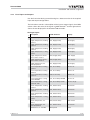
1
SAUTER flexotron®800
heating
Manual
P100013115 A
Sachnummer
flexotron®800

2/125
P100013115 A
flexotron®800
Content
Content
1 Generell notes
1.1Disclaimer
1.2Trademarks
2 About the manual
2.1
Further information
9
9
9
11
11
3 About flexotron®80013
3.1
Selecting the application
13
3.2
Select language
14
3.3
Heating application program
14
®
3.4flexotron 800 hardware overview
16
3.5flexotron®800 model overview
16
3.6
Technical data
17
3.6.1
Terminal positions on flexotron® 800
18
P100013115 A
4 Installation and terminal assignment
4.1Installation
4.2
Terminal assignment
4.2.1
Power supply
4.2.2
Inputs and outputs
4.2.3
List of inputs and outputs
19
19
20
20
20
23
5Commissioning
5.1
Step-by-step guide
35
35
6Functions
6.1
Heating control
6.1.1
General information
6.1.2Controllers
6.1.3
Control characteristics
6.1.4
Adjusting the characteristics
6.1.5
Temperature limits
6.1.6
Priority of heating over hot water
6.1.7
Pump control
6.1.8
Frost protection
6.1.9
Wind compensation
6.1.10
Building inertia and Boost
6.1.11
Night reduction
6.1.12
Start time optimisation
6.1.13
Power limitation
6.1.14
M-bus power limitation
6.2
Cooling system
6.2.1
General information
6.2.2Controller
6.2.3
Dew point control
6.2.4
Pump control
39
39
39
39
39
39
40
40
41
41
41
41
42
42
43
43
44
44
44
44
44
3/125
flexotron®800
Content
6.2.5
Starting the cooling unit
6.2.6
Eco/comfort function
6.2.7
Temperature limiter
6.2.8
Bypass valve (frost protection in the primary cooling system)
6.3
Domestic hot water
6.3.1
General information
6.3.2Controller
6.3.3
Night reduction
6.3.4
Pump control (HW1 only)
6.3.5
Anti-legionellae function (HW1 only)
6.3.6
Priority of hot water over heating
6.4
Hot water preparation function
6.4.1
Priority of HP over HS
6.5
Pressure control
6.6
Boiler control
6.6.1
General information
6.6.2
Type of boiler control
6.6.3Setpoint
6.6.4
Minimum running time and stop time
6.6.5
Starting sequence
6.6.6
Boiler test operation
6.6.7
Boiler alarm
6.6.8
Boiler pump
6.6.9
Transport pump
6.6.10
Boiler return temperature
6.7
Extra control loop
6.8
Cold water consumption
6.8.1Values
6.8.2
Alarm
6.9
Energy consumption
6.9.1
Consumption values
6.9.2
Performance values
6.9.3
Leakage monitoring
6.9.4Alarm
6.10
Electricity meter
6.10.1
Consumption values
6.11
Extra timer outputs
6.12Alarm
6.12.1
Alarm handling
6.12.2
Alarm priority
6.12.3
Alarm text
7 Display, LEDs and buttons
7.1Display
7.2
Light-emitting diode (LED)
7.3Buttons
7.4
Menu navigation
4/125
44
44
45
45
45
45
45
45
45
45
46
46
46
46
47
47
47
50
50
50
51
51
51
51
51
52
52
52
53
53
53
53
53
54
54
54
54
54
54
54
55
57
57
57
57
58
P100013115 A
flexotron®800
Content
P100013115 A
8 Access rights
8.1
Logging in
8.2
Logging out
8.3
Changing the code
8.4
Forgotten password
8.5
Changing the password to deactivate automatic logout 61
61
62
62
63
63
9Configuration
9.1
Alarm settings
9.1.1
Alarm limits
9.1.2
Alarm delay
9.2
Inputs and outputs
9.2.1
General information
9.2.2
Analogue inputs (AI)
9.2.3
Digital inputs (DI)
9.2.4
Universal inputs (UI)
9.2.5
Analogue outputs
9.2.6
Digital outputs
9.3
Sensor settings
9.4Supply
9.4.1
Parallel shift 9.4.2
Maximum limitation
9.4.3
Minimum limitation
9.4.4
Setpoint auto-correction
9.4.5
Wind compensation
9.4.6Optimisation
9.4.7
Power limitation
9.4.8
Dew point control
9.5
Return temperature limitation
9.5.1
Maximum return temperature
9.5.2
Max delta-T HP/HS
9.5.3
Minimum return temperature
9.5.4
Return limitation factor
9.6
Boiler control
9.6.1
General information
9.6.2
Boilers 1-4
9.6.3Pumps
9.7
Pump stop
9.8
Twin/single pump
9.9
Run indication/motor protection
9.10
Actuator type
9.11
Actuator run time, 3-point actuators
9.12
Actuator test run
9.13
Leakage monitoring
9.14
Pulse inputs
9.15
Alarm configuration
9.16Communication
9.16.1
Modbus communication
9.16.2
Communication port 2
65
65
65
67
68
68
68
69
69
70
70
70
71
72
72
72
72
73
74
75
75
76
76
76
77
77
77
77
78
79
80
81
82
83
83
84
84
85
85
91
91
92
5/125
flexotron®800
Content
9.16.3
Dial-up modem
9.16.4
Alarm forwarding via SMS 9.17
Other parameters
9.17.1
General information
9.17.2HW1
9.17.3HP1
9.18System
9.18.1
Changing the language
9.18.2
Selecting the start display – text normally shown
9.18.3
Automatic summer/winter time change-over
9.18.4
Controller bus address 9.18.5
Remote operation using the display 9.18.6
Automatic logout
10Settings
10.1
Actual value / setpoint
10.1.1
HS1, HS2 and HS3
10.1.2CS1
10.1.3
HW1 and HW2
10.1.4HP1
10.1.5Boiler
10.1.6
Additional control loop
10.2
Temperature control
10.2.1
General information
10.2.2
HS1, HS2 and HS3
10.2.3CS1
10.2.4
HW1 and HW2
10.2.5Boiler
10.3Manual/auto
10.3.1
General information
10.3.2
HS1, HS2 and HS3
10.3.3CS1
10.3.4
HW1 and HW2
10.3.5HP1
10.3.6Boiler
10.3.7
Additional control loop
10.4
ECO / comfort function
10.4.1
General information
10.4.2
HS1, HS2, HS3, HW1, HW2 and CS1
10.5
Clock / timer outputs
10.5.1
General information
10.5.2
Time / date
10.5.3
Timer outputs
10.6Holidays
10.7
Energy / cold water
10.7.1
Heating meter
10.7.2
Cold water meters CW1 and CW2
10.7.3
Electricity meter
10.7.4
Leakage monitoring
6/125
94
94
94
94
96
96
97
97
97
98
98
99
99
101
102
102
103
105
106
106
108
108
108
108
109
109
109
110
110
110
111
112
112
112
114
114
114
114
116
116
116
116
117
117
117
118
118
118
P100013115 A
flexotron®800
Content
P100013115 A
10.8
Running mode
10.8.1Alarms
10.8.2
Inputs / outputs
10.8.3
Extra sensors
119
119
119
120
11Expansion units
11.1
Port 1
11.2
Port 2
11.3Connection
11.3.1
M-bus meters
11.3.2
Expansion units
121
121
121
122
122
122
12Other functions
12.1
Alarm handling
12.2
Individual text field 12.3
Version number
123
123
124
124
7/125
flexotron®800
8/125
P100013115 A
flexotron®800
Generell notes
1
Generell notes
1.1
Disclaimer
The information in this user manual has been carefully checked and judged to be
correct. Fr. Sauter AG makes no guarantee regarding the content of this manual
and requests the reader to report any errors, inaccuracies or unclear formulations
so that they can be corrected. The information in this document is subject to
change without notice.
The software described in this document is supplied under licence and may
be used or copied only in accordance with the terms of the licence. No part of
this document may be reproduced or transmitted in any form, in any fashion,
electronically or mechanically, without the express, written permission of Fr.
Sauter AG.
1.2
Trademarks
flexotron® is a registered trademark of Fr. Sauter AG.
Windows, Windows 2000, Windows XP, and Windows Server 2003 are registered
trademarks of Microsoft Corporation.
Some product names mentioned in this document are used for identification
purposes only and may be the registered trademarks of their respective
companies.
Version A, March 2014
Software version: 3.2
P100013115 A
9/125
flexotron®800
10/125
P100013115 A
flexotron®800
About the manual
2
About the manual
This manual covers all the models in the flexotron®800 series used for heating
control. This revised version contains program functions for software version 3.2.
2.1
Further information
More information about flexotron®800 can be found in:
• SAUTER CASE flexotron® manual – Manual on configuration of the controllers
using the SAUTER CASE flexotron® PC software.
• Modbus network variables – List of variables for Modbus communication
• CE declaration of conformity, flexotron®800
The information can be downloaded from www.sauter-controls.com/en.
P100013115 A
11/125
flexotron®800
12/125
P100013115 A
flexotron®800
About flexotron®800
3
About flexotron®800
The flexotron®800 series comprises three sizes of model, with 8, 15 or 28 inputs
and outputs.
In each model of flexotron®800, all applications are loaded in a separate memory
area. All functions and configurations can be performed using the displays and
buttons or using the CASE flexotron® configuration tool, installed on a PC and
connected via a communication cable.
The controllers are available with or without a display and buttons. For units
without a display and buttons a separate, RDB800 display with buttons can be
connected via a cable.
The number of inputs and outputs can be increased by connecting either one
or two expansion units to port 2. The flexotron®800 models with two ports are
available only on request.
3.1
Selecting the application
On delivery, the main memory of the flexotron®800 controller is empty. All the
application programs are located in a separate memory area.
On the first start-up, the controller starts a special program for downloading the
required application to the main memory.
flexotron®800 Controller
08:01:01 00:00
Select application
with down arrow
First press OK to set the date and time. Use the Up and Down buttons to change
the parameters and the Right and Left buttons to move between fields. Then
press OK to confirm the date. The cursor automatically skips to the time. Set the
time in the same way as the date. Press OK to confirm.
Press the down arrow to go to “Select application”. Confirm your selection with
the Right button.
→
Ventilation
Heating
Expansion Unit 1
Expansion Unit 2
Press the down arrow to go to “Select application”. Confirm your selection with
the Right button.
P100013115 A
13/125
flexotron®800
About flexotron®800
3.2
Select language
In the basic display, press the Right button three times to go to the language
selection.
Heating
Choose language
English
Accept changes:No
Press OK to choose the language. Use the Up and Down buttons to select the
language. Press OK to confirm.
After a few seconds, the start display for the selected application appears in
English. If you selected a language other than English, the display then appears
in the selected language.
Heating controller
08:06:03 09:32
HS1
Sp: 19.5 IW: 20.1°C
3.3
Heating application program
The temperature controllers are PI controllers for regulating heating circuits,
cooling circuits and boilers, as well as PID controllers for regulating domestic
hot water. These controllers can be linked to various control functions and to
analogue and digital inputs and outputs. The user can freely select the functions
and the inputs and outputs. The only restriction to this is the number of physical
inputs and outputs on the various models.
The flexotron®800 is designed for mounting on a DIN rail.
Heating control includes the following functions among others:
Heating
Controlling 1 to 3 heating systems with weather-dependent flow and control
options using room sensors and/or return sensors.
Optimisation function
Optimisation of the starting time for reaching the comfort temperature after
lowering in ECO mode.
Cooling
Controlling a cooling system with dew point control. The setpoint can be fixed or
weather-dependent.
14/125
P100013115 A
flexotron®800
About flexotron®800
Domestic hot water
Either one or two domestic hot water circuits and a hot water preparation control
unit.
Additional control loop
Differential thermostat function for moving fluids between two points depending
on the temperature difference.
Pump differential pressure control
A control loop for constant pressure.
Boiler control
For sequential control of 1 to 4 boilers: 1-step, 2-step or modulating vessels.
You can choose between a fixed setpoint, a weather-dependent setpoint or the
highest of the other setpoints configured for the heating system.
Timer outputs
Up to 5 individually configurable clock channel outputs for controlling functions
such as door locks and lighting.
Timer
Individual day programmes, holiday schedules, year-long clock.
Water consumption
Digital input for displaying water consumption
Energy consumption
Digital input for displaying energy consumption
P100013115 A
15/125
flexotron®800
About flexotron®800
3.4
flexotron®800 hardware overview
Model
RDT808 RDT815 RDT815 RDT815 RDT828 RDT828 RDT828
F211
F011
F211
F221
F011
F211
F221
Analogue inputs
2
4
4
4
4
4
4
Digital inputs
3
4
4
4
8
8
8
Universal inputs
(UI)
-
-
-
-
4
4
4
Analogue outputs
1
3
3
3
5
5
5
Digital Outputs
(DO)
2
4
4
4
7
7
7
RS485*
Yes
Yes
Yes
No
Yes
Yes
No
WEB (TCP/IP)
No
No
No
Yes
No
No
Yes
Display
Yes
No
Yes
Yes
No
Yes
Yes
Ext. display
No
Optional No
No
Optional No
No
* RS485 communication port not available for versions with WEB (TCP/IP).
However, a 2-port flexotron®800 with TCP/IP and RS485 can be selected on
request, with the RS485 port used for expansion units etc.
3.5
16/125
flexotron®800 model overview
Model with display
Model without display
Description
RDT808F211,
RDT815F211,
RDT828F211
RDT815F011, RDT828F011 Standard controller with RS485
port
RDT815F221,
RDT828F221
Controller with TCP/IP port and
built-in webserver
P100013115 A
flexotron®800
About flexotron®800
3.6
Technical data
Protection class
IP 20 when installed
Display
4 lines of 20 characters Illumination
LEDs
Yellow
Adjustable parameter
Red
Alarm indicator
Clock
24-hour system clock with battery backup,
automatic summer/winter changeover
Power supply
24 V AC ±15%, 50…60 Hz or 21…36 V DC
Power consumption
10 VA, 4 W (DC), WEB model: 12 VA, 5 W (DC)
Start-up current
20 A (2 ms)
Dimensions
148x123x58 (WxHxD including terminals)
Housing
Euronorm (8.5 modules wide)
Mounting
On DIN rail
Operation
Environmental conditions according to IEC 721-3-3
Class 3k5
Ambient temperature
0...50°C
Ambient humidity
max. 95% rh
Mechanical requirements according to IEC721-3-3
Class 3M3
Vibration
IEC60068-2-6, Test FC, sinusoidal vibration
Shock
IEC60068-2-27, Test Ea
Transport
Ambient conditions according to IEC 721-3-2
Class 2k3
Ambient temperature
-20...70°C
Ambient humidity
max. 95% rh
Mechanical requirements according to IEC721-3-2
Class 2M2
Vibration
IEC60068-2-6, Test FC, sinusoidal vibration
Shock
IEC60068-2-27, Test Ea
Free fall
IEC60068-2-27, Test Ed
Storage
Ambient conditions according to IEC 721-3-1
Class 1k3
Ambient temperature
-20...70°C
Ambient humidity
max. 95% rh
Battery
Type
Replaceable lithium cell, CR2032
Battery life
More than 5 years
Warning
Low battery warning
Battery backup
Memory and clock
Communication
The basic version of flexotron®800 can communicate with Modbus. You do not need an activation
code.
The flexotron®800 controller is available with a communication port for TCP/IP.
CE label
Conforms with the EMC standards: CENELEC EN61000-6-3:2001, CENELEC EN61000-6-1:2001.
Inputs
Analogue inputs AI
Configurable as 0…10 V DC or Ni1000, 12 bit A/D
Digital inputs DI
Potential-free connection
Universal inputs UI
Can be used as either analogue or digital input (see information above)
P100013115 A
17/125
flexotron®800
About flexotron®800
Outputs
Analogue outputs AO
Digital outputs DO
Optional
WEB (TCP/IP port)
With 2 ports
External operating unit, RDB800
Configurable as 0…10 V DC; 2…10 V DC;
10…0 V DC or 10…2 V DC
8 bit D/A, short-circuit protected
Mosfet outputs, 24 V AC/DC, constant 2 A. Max. 8 A total.
Replaces the RS485 port for flexotron®800
Two serial ports or one serial port and a TCP/IP port
Used with flexotron®800 without display
3.6.1 Terminal positions on flexotron® 800
18/125
P100013115 A
flexotron®800
Installation and terminal assignment
4
Installation and terminal assignment
4.1
Installation
The flexotron®800 controller can be mounted in a DIN-standard housing
(minimum 9 modules), on a DIN rail in a cabinet or, using a suitable mounting kit,
in a cabinet door or control panel.
Ambient temperature: 0…50 °C.
Humidity: Max: 95 % rh, non-condensing.
Example of terminal assignment on RDT828.
LS
MM
+24 V
0...10 V
Actuator
0...10 V
AO1
AO2
AO3
AO4
AO5
Modbus
DI1
DI2
DI3
DI4
DI5
DI6
DI7
DI8
RJ45
1
D+
2
D3
C
4
E
9
10
11
12
13
14
15
16
17
18
19
20
21
22
Contact
AO1 - 5
DI1 - 8
TCP/IP
A10709
28
27
UI1
26
UI2
25
24
UI3
23
UI4
AI3
AI4
AI1
AI2
RJ12
UI1 - 4
AI1 - 4
34
33
32
31
30
29
42
41
40
39
38
37
36
35
+
Ext.
disp.
LS
DO1
DO2
DO3
DO4
DO5
DO6
DO7
24 V
LS
MM
FET
DO1 - 7
MM
+24 V
DI contacts
24V~
P100013115 A
Relay
24V~
Temp. sensors
Ni1000
RJ12
RDT828F011
RJ45
Options:
RDT828F221
Lamp
24V~
Transmitter
0...10 V
LS
2...10 A
TCP/IP
Ext.
disp.
19/125
flexotron®800
Installation and terminal assignment
4.2
Terminal assignment
At the end of this section there are terminal assignment plans that show the
available factory-set configurations as well as blank wiring diagrams.
Because most functions of the inputs and outputs depend on the programming
of the device, the definitive wiring diagram cannot be completed until the installer
has assigned the inputs and outputs.
It is important to make sure that the wiring is correctly carried out in accordance
with the instructions in this manual.
4.2.1 Power supply
24 V~ ±15%, 50…60 Hz or 21…36 V DC
If the flexotron®800 controller and the connected actuators are supplied by the
same transformer, the same transformer pole must be used as reference earth
for the entire installation. If the reference earth is not the same, the equipment will
not function properly and serious damage may occur.
4.2.2 Inputs and outputs
The list of inputs and outputs in section 4.2.3 gives an overview and helps you
configure them.
Analogue inputs
Analogue inputs must be connected to an earth terminal in the same terminal
block as the input.
Depending on the configuration, analogue inputs can be used either for Ni1000
temperature sensors or for 0…10 V DC analogue input signals, for example from
a pressure transmitter.
Digital inputs
Digital inputs must be connected to the +24V terminal. Digital inputs may only
be connected with voltageless contacts. Any external voltage applied to a digital
input may harm the unit.
Universal inputs
A universal input can be configured to act as either an analogue input or as a
digital input.
Depending on the configuration, a universal input acting as an analogue input
can be used for either Ni1000 temperature sensors or for 0…10 V DC analogue
input signals, for example from a pressure transmitter.
Universal inputs configured as analogue inputs must be connected to an earth
terminal in the same terminal block as the input.
20/125
P100013115 A
flexotron®800
Installation and terminal assignment
A universal input configured as a digital input must be connected to terminal
+24V just like other digital inputs and may only be connected using voltageless
contacts.
Analogue outputs
Analogue outputs must be connected to the earth terminal in the AO terminal
block.
All analogue outputs can be individually configured for the following signals:
• 0…10 V DC
• 2…10 V DC
• 10…0 V DC
• 10…2 V DC
If the flexotron®800 controller and the connected actuators are supplied by the
same transformer, the same transformer pole must be used as reference earth
for the entire installation. If the reference earth is not the same, the equipment will
not function properly and serious damage may occur.
Digital outputs
Digital outputs should normally be connected to terminal 42 LS. Terminal 42 LS is
internally connected to LS and supplies 24 V ~ or 24 V = depending on the power
supply.
All the digital outputs are Mosfet transistors. The outputs are connected internally
to LS and are restricted to not more than 2 A per output. However, the total load
for all the digital outputs may not exceed 8 A.
A number of alternative terminal assignments are possible depending on the
relay type and the power supply to the flexotron®800 controller.
24 V~ power supply and 24 V~ relay
P100013115 A
21/125
flexotron®800
Installation and terminal assignment
24 V= power supply and 24 V= relay
24 V~ power supply and 24 V= relay
24 V= power supply and 24 V~ relay
22/125
P100013115 A
flexotron®800
Installation and terminal assignment
4.2.3 List of inputs and outputs
Use the lists below during commissioning for a better overview of the required
input and output configurations.
The left column contains a description of the input or output signal, the middle
column shows the name of the signal in CASE flexotron® and the right column
shows the text displayed in the flexotron®800 controller.
Analogue inputs
P Description
P100013115 A
CASE flexotron®
Display
Outdoor-temperature sensor
Outdoor Temp
Outd Temp
Supply temperature, heating
system 1
HS1, Supply Temp
HS1 Supply
Supply temperature, heating
system 2
HS2, Supply Temp
HS2 Supply
Supply temperature, heating
system 3
HS3, Supply Temp
HS3 Supply
Supply temperature, cooling
system
CS1, Supply Temp
CS1 Supply
Supply temperature, domestic hot water circuit 1
HW1, Supply Temp
HW1 Supply
Supply temperature, domestic hot water circuit 2
HW2, Supply Temp
HW2 Supply
Supply temperature, hot
water preparation
HP1, Supply Temp
HP1 Supply
Room temperature, heating
system 1
HS1, Room Temp
HS1 Room
Room temperature, heating
system 2
HS2, Room Temp
HS2 Room
Room temperature, heating
system 3
HS3 Room Temp
HS3 Room
Room temperature, cooling
system Ni1000
CS1, Room Temp Ni1000
CS1 Room
Room temperature, cooling
system 0...10V
CS1, Room Temp 0-10V
CS1 Room (V)
Return temperature, heating
system 1
HS1, Return Temp
HS1 Return
Return temperature, heating
system 2
HS2, Return Temp
HS2 Return
Return temperature, heating
system 3
HS3, Return Temp
HS3 Return
Return temperature, cooling
system
CS1, Return Temp
CS1 Return
Return temperature, hot
water 1
HW1, Return Temp
HW1 Return
Return temperature, hot
water preparation
HP1, Return Temp
HP1 Return
Wind sensor, 0…10 V DC
Wind speed
Wind
23/125
flexotron®800
Installation and terminal assignment
P Description
CASE flexotron®
Display
Differential pressure sensor,
0…10 V DC
DP
Pressure
Humidity sensor, 0...10 V
RH
RH
Primary heating circuit, supply temperature
HP Supply Temp
HP Supply
Primary heating circuit, return HP Return Temp
temperature
HP Return
Primary cooling circuit, supply temperature
CP Supply Temp
CP Supply
Primary cooling circuit, return CP Return Temp
temperature
CP Return
Extra temperature sensor 1
Extra Sensor Temp 1
Ext.sensor1
Extra temperature sensor 2
Extra Sensor Temp 2
Ext.sensor2
Extra temperature sensor 3
Extra Sensor Temp 3
Ext.sensor3
Extra temperature sensor 4
Extra Sensor Temp 4
Ext.sensor4
Extra temperature sensor 5
Extra Sensor Temp 5
Ext.sensor5
Boiler temperature return
Boiler Return Temp
HB Return
Boiler temperature
Boiler Temp
HB-supply
Return temperature for
boiler 1
Boiler 1, return Temp
HB1-return
Return temperature for
boiler 2
Boiler 2, return Temp
HB2-return
Return temperature for
boiler 3
Boiler 3, return Temp
HB3-return
Return temperature for
boiler 4
Boiler 4, return Temp
HB4-return
Temperature for differential
thermostat function
Extra Circuit Sensor 1
Ext circS1
Temperature for differential
thermostat function
Extra Circuit Sensor 2
Ext circS2
CASE flexotron®
Display
Operating mode/alarm circulation pump, P1A-HS1
HS1, Pump A Indication
HS1-PumpA
Operating mode/alarm circulation pump, P1B-HS1
HS1, Pump B Indication
HS1-PumpB
Operating mode/alarm circulation pump, P1A-HS2
HS2, Pump A Indication
HS2-PumpA
Operating mode/alarm circulation pump, P1B-HS2
HS2, Pump B Indication
HS2-PumpB
Operating mode/alarm circulation pump, P1A-HS3
HS3, Pump A Indication
HS3-PumpA
Digital inputs
P Description
24/125
P100013115 A
flexotron®800
Installation and terminal assignment
P Description
P100013115 A
CASE flexotron®
Display
Operating mode/alarm circulation pump, P1B-HS3
HS3, Pump B Indication
HS3-PumpB
Operating mode/alarm circulation pump, P1A-CS1
CS1, Pump A Indication
CS1-PumpA
Operating mode/alarm circulation pump, P1B-CS1
CS1, Pump B Indication
CS1-PumpB
Operating mode/alarm circulation pump, P1-HW1
HW1, Pump Indication
HW1-Pump
Charge pump P1-HP1
HP1, Pump Indication
HP1-Pump
Operating mode/alarm, frequency converter for pressure control
Frequency
Frequencer
Pressure switch, expansion
vessel
Expansion vessel
Exp. vessel
External alarm
External alarm
External alarm
External power limitation
External power limit
Effect limiter
Volume pulse, hot water
consumption
Water pulse
Heating pulse
Energy pulse, heating consumption
Energy pulse
Energy pulse
Volume pulse, cold water
consumption 1
CW1 pulse
CW1 pulse
Volume pulse, cold water
consumption 2
CW2 pulse
CW2 pulse
Energy pulse, electricity
meter
Electric pulse
Electric pulse
CS1 start
CS1, Start
CS1-start
Boiler alarm
Boiler alarm
Boiler alarm
Operating mode/alarm for
boiler 1
Boiler 1 Indication
HB1-ind
Operating mode/alarm for
boiler 2
Boiler 2 Indication
HB2-ind
Operating mode/alarm for
boiler 3
Boiler 3 Indication
HB3-ind
Operating mode/alarm for
boiler 4
Boiler 4 Indication
HB4-ind
Operating mode/alarm for
boiler pump 1
Boiler 1 Pump Indication
HB1-pump
Operating mode/alarm for
boiler pump 2
Boiler 2 Pump Indication
HB2-pump
Operating mode/alarm for
boiler pump 3
Boiler 3 Pump Indication
HB3-pump
Operating mode/alarm for
boiler pump 4
Boiler 4 Pump Indication
HB4-pump
Operating mode/alarm for
transport pump
Transport Pump Indication
Transp pump
25/125
flexotron®800
Installation and terminal assignment
P Description
External stop for boiler
control
CASE flexotron®
Display
External Stop Boiler 1-4
External stop
Pressure/flow alarm for boiler HB Pressure/Flow error
circuit
HB flow/pressure
Extra Circuit pump IndicaOperating mode/alarm for
extra control circuit (thermos- tion
tat function)
Ext circ pump
The universal inputs on the RDT828 can each be configured as either analogue
or digital inputs and used for any of the analogue input signals above.
Analogue outputs
CASE flexotron®
Display
Actuator, heating system 1,
HS1
HS1, Valve
HS1 Actuator
Actuator, heating system 2,
HS2
HS2, Valve
HS2 Actuator
Actuator, heating system 3,
HS3
HS3, Valve
HS3 Actuator
Actuator, cooling system 1, CS1 CS1, Valve
CS1 Actuator
Actuator, domestic hot water
circuit 1, HW1
HW1, Valve
HW1 Actuator
Actuator, domestic hot water
circuit 2, HW2
HW2, Valve
HW2 Actuator
Frequency converter, pressure
control
DP, Valve
Pressure Act.
P Description
26/125
Split of one of the above circuits Seq control of valve
HS1 - HP1
(not differential pressure)
Seq control
Boiler 1 vessel
Boiler 1, Modulating vessel
HB1 mod vessel
Boiler 2 vessel
Boiler 2, Modulating vessel
HB2 mod vessel
Boiler 3 vessel
Boiler 3, Modulating vessel
HB3 mod vessel
Boiler 4 vessel
Boiler 4, Modulating vessel
HB4 mod vessel
Boiler 1 return valve actuator
Boiler 1, Returntemp Valve
HB1 ret temp valve
Boiler 2 return valve actuator
Boiler 2, Returntemp Valve
HB2 ret temp valve
Boiler 3 return valve actuator
Boiler 3, Returntemp Valve
HB3 ret temp valve
Boiler 4 return valve actuator
Boiler 4, Returntemp Valve
HB4 ret temp valve
P100013115 A
flexotron®800
Installation and terminal assignment
Digital outputs
P Description
P100013115 A
CASE flexotron®
Display
Start/stop pump, P1A-HS1
HS1, Pump A Start
HS1-PumpA
Start/stop pump, P1B-HS1
HS1, Pump B Start
HS1-PumpB
Start/stop pump, P1A-HS2
HS2, Pump A Start
HS2-PumpA
Start/stop pump, P1B-HS2
HS2, Pump B Start
HS2-PumpB
Start/stop pump, P1A-HS3
HS3, Pump A Start
HS3-PumpA
Start/stop pump, P1B-HS3
HS3, Pump B Start
HS3-PumpB
Start/stop pump, P1A, CS1
CS1, Pump A Start
CS1-PumpA
Start/stop pump, P1B, CS1
CS1, Pump B Start
CS1-PumpB
Start/stop pump, P1-HW1
HW1, Pump Start
HW1-Pump
Start/stop water preparation
pump, P1-HP1
HP1, Pump Start
HP1-Pump
Start/stop frequency converter,
pressure control
Frequencer Start
Frequencer
Sum alarm A + B
Sum alarm
Sum alarm
Sum alarm A
Sum alarm A
A-sum alarm
Sum alarm B
Sum alarm B
B-sum alarm
Extra timer output 1
Timer Channel 1
Timer1
Extra timer output 2
Timer Channel 2
Timer2
Extra timer output 3
Timer Channel 3
Timer3
Extra timer output 4
Timer Channel 4
Timer4
Extra timer output 5
Timer Channel 5
Timer5
Increase 3-point actuator HS1
HS1, Valve Increase
Inc HS1-Act.
Reduce 3-point actuator HS1
HS1, Valve Decrease
Dec HS1-Act.
Increase 3-point actuator HS2
HS2, Valve Increase
Inc HS2-Act.
Reduce 3-point actuator HS2
HS2, Valve Decrease
Dec HS2-Act.
Increase 3-point actuator HS3
HS3, Valve Increase
Inc HS3-Act.
Reduce 3-point actuator HS3
HS3, Valve Decrease
Dec HS3-Act.
Increase 3-point actuator CS1
CS1, Valve Increase
Inc CS1-Act.
Reduce 3-point actuator CS1
CS1, Valve Decrease
Dec CS1-Act.
Increase 3-point actuator HW1
HW1, Valve Increase
Inc HW1-Act.
27/125
flexotron®800
Installation and terminal assignment
CASE flexotron®
Display
Reduce 3-point actuator HW1
HW1, Valve Decrease
Dec HW1-Act.
Increase 3-point actuator HW2
HW2, Valve Increase
Inc HW2-Act.
Reduce 3-point actuator HW2
HW2, Valve Decrease
Dec HW2-Act.
Bypass valve, CS1
CS1, Bypass Valve
CS1 bypass valve
CS1, start cooling unit
CS1, Cool unit start
CS1 Cooling unit
Start/stop vessel 1
Boiler 1, vessel
HB1-start1
Start/stop vessel 1 high power
Boiler 1, vessel (High effect) HB1-start2
Start/stop vessel 2
Boiler 2, vessel
Start/stop vessel 2 high power
Boiler 2, vessel (High effect) HB2-start2
Start/stop vessel 3
Boiler 3, vessel
Start/stop vessel 3 high power
Boiler 3, vessel (High effect) HB3-start2
Start/stop vessel 4
Boiler 4, vessel
Start/stop vessel 4 high power
Boiler 4, vessel (High effect) HB4-start2
Start/stop pump, boiler 1
Boiler 1, Pump Start
HB1-pump
Start/stop pump, boiler 2
Boiler 2, Pump Start
HB2-pump
Start/stop pump, boiler 3
Boiler 3, Pump Start
HB3-pump
Start/stop pump, boiler 4
Boiler 4, Pump Start
HB4-pump
Start/stop transport pump
Transport Pump, Start
Transp pump
Start/stop pump, extra control
circuit
Extra Circuit Pump
Ext circ pump
P Description
28/125
HB2-start1
HB3-start1
HB4-start1
P100013115 A
flexotron®800
Installation and terminal assignment
Factory setting for RDT828 terminal assignment
(See also: terminal assignment diagram, 3.6.1)
-
LS
-
MM
-
Power supply 24 V AC ±15%. 50/60 Hz,
or 24 V DC
1
D+
2
D-
Earth conductor
3
C
4
E
+24 V +24 V DC. Reference point for digital inputs DI
RS485 Modbus (not with web (TCP/
IP) models)
42 LS
Reference point for digital outputs DO
-
-
41 DO1
Start/stop pump, P1A-HS1
-
-
40 DO2
Start/stop pump, P1B-HS1
-
-
39 DO3
Increase 3-point actuator HS1
38 DO4
Reduce 3-point actuator HS1
9
DI1
Operating mode/alarm circulation
pump, P1A-HS1
37 DO5
Start/stop pump, P1-HW1
10
DI2
Operating mode/alarm circulation
pump, P1B-HS1
36 DO6
Start/stop pump, P1A-HS2
11
DI3
Operating mode/alarm circulation
pump, P1A-HS2
35 DO7
Sum alarm
12
DI4
Operating mode/alarm circulation
pump, P1-HW1
13
DI5
Water pulse, hot water consumption
34
Reference potential for analogue inputs AI
14
DI6
Energy pulse, heating consumption
33 AI1
Outdoor temperature sensor
15
DI7
Volume pulse, cold water consumption 1
32 AI2
Supply temperature, heating system 1
16
DI8
Pressure switch, expansion vessel
31
Reference potential for analogue inputs AI
30 AI3
Supply temperature, domestic hot water circuit 1
17
29 AI4
Return temperature, heating system 1
18
AO1
Actuator, heating system 1, HS1
19
AO2
Actuator, domestic hot water circuit 1,
HW1
Reference potential for analogue
outputs AO
28
Reference potential for universal inputs UI
20
AO3
Actuator, heating system 2, HS2
27 UI1
Supply temperature, heating system 2
21
AO4
not used
26 UI2
Return temperature, heating system 2
22
AO5
not used
25
Reference potential for universal inputs UI
24 UI3
Room temperature, heating system 1
23 UI4
Room temperature, heating system 2
P100013115 A
29/125
flexotron®800
Installation and terminal assignment
Factory setting for RDT815 terminal assignment
(See also: terminal assignment diagram, 3.6.1)
LS
MM
Power supply 24 V AC ±15%. 50/60 Hz
or 24 V DC
1
D+
2
D-
Earth conductor
3
C
4
E
+24V +24 V DC. Reference point for digital inputs DI
RS485 Modbus (not with web (TCP/IP)
models)
42 LS
Reference point for digital outputs DO
-
-
41 DO1
Start/stop pump, P1A-HS1
-
-
-
-
9
DI1
Operating mode/alarm circulation pump,
P1A-HS1
10
DI2
Operating mode/alarm circulation pump,
P1B-HS1
40 DO2
Start/stop pump, P1B-HS1
39 DO3
Start/stop pump, P1-HW1
38 DO4
Sum alarm
34
Reference potential for analogue inputs AI
11
DI3
Operating mode/alarm circulation pump,
P1-HW1
33 AI1
Outdoor temperature sensor
12
DI4
Pressure switch, expansion vessel
32 AI2
Supply temperature, heating system 1
31
Reference potential for analogue inputs AI
17
30 AI3
Supply temperature, domestic hot water circuit 1
18
AO1
Actuator, heating system 1, HS1
29 AI4
Return temperature, heating system 1
19
AO2
Actuator, domestic hot water circuit 1,
HW1
20
AO3
Not used
30/125
Reference potential for analogue outputs
AO
P100013115 A
flexotron®800
Installation and terminal assignment
Factory setting for RDT808 terminal assignment
(See also: terminal assignment diagram, 3.6.1)
LS
Power supply 24 V AC ±15%. 50/60 Hz
or 24 V DC
1
D+
2
D-
Earth conductor
3
C
+24 V DC. Reference point for digital inputs DI
4
E
42 LS
Reference point for digital outputs DO
-
41 DO1
Start/stop pump, P1A-HS1
-
40 DO2
Start/stop pump, P1B-HS1
-
34
Reference potential for analogue inputs AI
9
DI1
Operating mode/alarm circulation pump,
P1A-HS1
33 AI1
Outdoor-temperature sensor
10
DI2
Operating mode/alarm circulation pump,
P1B-HS1
32 AI2
Supply temperature, heating system 1
11
DI3
Not used
MM
+24V
Reference potential for analogue outputs
AO
17
18
P100013115 A
RS485 Modbus (not with web (TCP/IP)
models)
AO1
Actuator, heating system 1, HS1
31/125
flexotron®800
Installation and terminal assignment
Blank wiring diagram for RDT828
-
LS
Power supply 24 V AC or 24 V DC,
±15%. 50/60 Hz
1
D+
-
MM
2
D-
Earth conductor
3
C
4
E
42 LS
-
-
41 DO1
-
-
40 DO2
-
-
38 DO4
9
DI1
37 DO5
10
DI2
36 DO6
11
DI3
35 DO7
12
DI4
13
DI5
14
DI6
33 AI1
15
DI7
32 AI2
16
DI8
-
+24 V +24 V DC. Reference point for digital inputs DI
RS485 Modbus (not with web (TCP/
IP) models)
39 DO3
34
31
Reference potential for analogue inputs AI
Reference potential for analogue inputs AI
30 AI3
17
29 AI4
18
AO1
19
AO2
20
AO3
27 UI1
21
AO4
26 UI2
22
AO5
28
25
Reference potential for universal inputs UI
Reference potential for analogue
outputs AO
Reference potential for universal inputs UI
24 UI3
23 UI4
32/125
P100013115 A
flexotron®800
Installation and terminal assignment
Blank wiring diagram for RDT815
LS
Power supply 24 V AC or 24 V DC,
±15%. 50/60 Hz
1
D+
2
D-
Earth conductor
3
C
+24 V DC. Reference point for digital inputs DI
4
E
Reference point for digital outputs DO
-
-
41 DO1
-
-
40 DO2
-
-
9
DI1
10
DI2
11
DI3
12
DI4
MM
+24V
42 LS
RS485 Modbus (not with web (TCP/IP)
models)
39 DO3
38 DO4
Reference potential for analogue inputs AI
34
33 AI1
32 AI2
Reference potential for analogue inputs AI
31
17
Reference potential for analogue outputs
AO
30 AI3
18
AO1
29 AI4
19
AO2
20
AO3
Blank wiring diagram for RDT808
LS
MM
+24V
42 LS
Supply voltage 24 V AC or 24 V DC
±15%. 50/60 Hz
1
D+
2
D-
Protective earth
3
C
+24 V DC. Reference for digital inputs DI.
4
E
Reference for digital outputs DO.
-
41 DO1
-
40 DO2
9
DI1
33 AI1
10
DI2
32 AI2
11
DI3
34
Reference pole for analogue inputs AI
Reference pole for analogue outputs AO
17
18
P100013115 A
RS485 Modbus (not in WEB (TCP/IP)
models)
AO1
33/125
flexotron®800
34/125
P100013115 A
flexotron®800
Commissioning
5
Commissioning
General information
The flexotron®800 controller must be configured before use. The inputs and
outputs must be assigned and all important parameters must be set.
All commissioning can be done either using the flexotron®800 controller display or
an external RDB800 display unit.
CASE flexotron®
However, the best method is to configure the controller using CASE flexotron®.
CASE flexotron® is a PC configuration program specially developed to simplify
commissioning of the flexotron®800 series.
Using CASE flexotron®, the entire configuration and all settings can be prepared
on the computer and then loaded to the controller. Any number or configurations
can be saved on the computer for later use.
A communication cable is required in order to configure flexotron®800 with CASE
flexotron®.
Before it is configured, the flexotron®800 controller must be connected to the
power supply and the application program selected.
5.1
Step-by-step guide
For configuration using CASE flexotron®, see the CASE flexotron® manual.
For configuration using the controller display there are options, depending on the
user’s skill.
Option 1:
1. Go straight to sections 7 and 8, Display, LEDs and buttons and Access rights.
2. Once you are familiar with the buttons and menu system, connect the
controller to the power supply. Log in as administrator and go to the
“Configuration” menu.
3. For the time being, skip the configuration menu for the inputs and outputs and
start by configuring the control functions.
4. Go through the configuration menus in order and set all the required functions
and parameters. Use section 6 of the manual for reference. The list of input
and output functions in section 4.2.3 helps you keep track of the required
inputs and outputs.
5. Finally, configure the inputs and outputs.
P100013115 A
35/125
flexotron®800
Commissioning
6. Exit the “Configuration” menu and continue by making the settings within the
activated controller systems.
7. Set the control parameters in “Temperature control”.
8. Set the running times in the “ECO/Comf. mode” menu.
ÂÂ The flexotron®800 controller should now be ready for operation.
Option 2:
Read this manual in the order given below: The manual provides a step-by-step
guide to commissioning. The last sections of the manual describe menus and
functions that are not required during commissioning. For this reason, they are
not included in the following sections.
Functions
First read section 6, Functions. Some functions are essential for the controller
to operate correctly and must be set. Others are additional functions and do not
necessarily need to be set.
Section 4.2.3 contains a list of all analogue and digital inputs and outputs. Mark
all the inputs and outputs in the list that you will be using for the application.
Remember that the universal inputs on the RDT828 can each be configured as
either analogue or digital.
Display, buttons and LEDs
Section 7 describes how to use the controller buttons to navigate the
flexotron®800 menu system.
Access rights
See section 8: Logging into the flexotron®800.
Configuration
See Section 9: Configuration.
Connect the power supply to the controller. Use the buttons and menu system to
select the required functions in the configuration menu.
The unit is delivered preconfigured and all the inputs and outputs are assigned
to various functions, which you can change later. Section 4, Installation and
terminal assignment, includes two terminal assignment diagrams – one with
the preconfigured inputs and outputs and where you can put in your own
configurations.
Settings
Set the control parameters, P-band and I-time for temperature control. These
settings can be found in the temperature control menu of the controller system.
To set the alarm parameters, alarm levels and alarm delays, see section 9.1,
Alarm settings.
36/125
P100013115 A
flexotron®800
Commissioning
Time settings
See Section 10.5:
Setting the clock and calendar functions.
Setpoints
See Section 10.1:
Entering the setpoints for all active control loops.
Manual/automatic
See Section 10.3:
Description of manual operating mode. This is useful for testing the system.
Other functions
See section 12.1: Alarm handling etc.
P100013115 A
37/125
flexotron®800
38/125
P100013115 A
flexotron®800
Functions
6
Functions
6.1
Heating control
6.1.1 General information
The flexotron®800 can be configured for up to three heating systems: HS1, HS2
and HS3.
6.1.2 Controllers
The heating systems are controlled using PI controllers with an adjustable
P-band and I-time.
6.1.3 Control characteristics
The controllers have individual control characteristics for the relationship between
the supply temperature and the outdoor temperature.
Each characteristic has 8 schedule start points. The factory settings are the
Outdoor temperature values -20, -15, -10, -5, ±0, +5, +10, +15. These outdoor
temperature values cannot be changed using the buttons on the flexotron®800,
but only using CASE flexotron®. The corresponding supply temperatures,
however, can be set both on the flexotron®800 and using CASE flexotron®.
6.1.4 Adjusting the characteristics
Room temperature sensors can be used to correct the set control characteristics.
The average temperatures over a defined period of time are calculated. After this,
a parallel shift of the entire curve upward or downward is carried out, depending
on whether the difference between the room setpoint and the actual room value is
positive or negative. After comparison, the deviation is multiplied by the correction
factor and the sum is added to the current shift according to the following formula:
Shift = (room setpoint - average temp)*factor + current
shift
You can set how often this calculation takes place (0...24 h), as well as the
correction factor (0...100). The shift is limited to a maximum of ± 20 degrees.
P100013115 A
39/125
flexotron®800
Functions
6.1.5 Temperature limits
The heating systems have individually adjustable minimum and maximum
temperature limits for the supply and return. If the return temperature is not
within the set limits, the supply temperature is adjusted by a configurable factor
to eliminate the error. However, the supply setpoint may never be above or below
the set minimum or maximum setpoint.
The minimum limit is calculated as follows:
Supply shift = (minimum limit - return temp)
*limiting factor
The minimum limit can only result in a positive shift, otherwise the shift = 0
The maximum limit is calculated as follows:
Supply shift = (maximum limit - return temp)
*limiting factor
The maximum limit can only result in a negative shift, otherwise the shift = 0
Primary and secondary return temperature limits
The primary return temperature may not be more than 3 degrees (adjustable)
higher than the secondary return temperature. If the difference exceeds the set
value, the valve control signal is overridden in order to close the valve and thus
reduce the flow. This lowers the return temperature.
Inputs and outputs
AI
Return temperature HS1 and/or HS2
AI
Primary heating return temperature
6.1.6 Priority of heating over hot water
It is possible to give the heating circuits priority over the hot water circuits by
activating the corresponding function. If one of the heating circuits is a certain
(adjustable) number of degrees below the setpoint for an adjustable period of
time, the actuators of the hot water circuits are forced to close.
40/125
P100013115 A
flexotron®800
Functions
6.1.7 Pump control
Each circuit can be equipped with single or twin pumps. With twin pumps, only
one of the pumps is operated at a time. They automatically switch over once a
week. If the active pump fails, the inactive pump is automatically started up.
Pumps can be configured to stop according to the outdoor temperature, and
individual pump start and stop delays can be configured.
The pumps are moved for 5 minutes every day at 3 p.m.
6.1.8 Frost protection
If a controller is in Off or Manual mode and the outdoor temperature falls below
a set value, an adjustable minimum supply temperature is maintained and the
pump starts up.
6.1.9 Wind compensation
In order to compensate for cooling due to wind, a wind sensor can be connected
and a wind-based setpoint shift can be generated. The function provides an
adjustable shift factor (°C per m/s).
6.1.10Building inertia and Boost
The building inertia in relation to the heat storage capacity of the building
envelope can be set in hours (0-24).
The set inertia is used to control the effect of the outdoor temperature on the
control characteristics.
The outdoor temperature used to calculate the current supply temperature is an
average over the set time period. If the current outdoor temperature is to be used,
the period must be set to 0. For the daily average, set the period to 24.
Boost: At low outdoor temperatures, it is possible to temporarily shift the control
characteristic when changing from the night-time temperature to the comfort
temperature. This speeds up heating to the daytime temperature. The following
conditions apply:
• The daily average outdoor temperature is less than 17°C.
• The supply temperature must be above 25°C.
• The night reduction must be more than 2°C.
P100013115 A
41/125
flexotron®800
Functions
If these conditions are met, the starting time delay is calculated as follows:
Shift=factor*(17-outdoor temp)* night reduction
The factor can be set from 0…10. 0 means no start delay and 10 is the maximum
shift.
The running time in minutes for the shift is calculated as follows:
Running time = 1.6*(17-outdoor temp)
The running time is limited to a maximum of 60 minutes.
6.1.11Night reduction
The night reduction is set using the room temperature. To calculate the reduction
of the supply temperature, the set room temperature is multiplied by 3. The
flexotron®800 has individual time programmes for each heating system with two
comfort periods per day.
6.1.12Start time optimisation
This function is used to achieve the required room temperature if the comfort
period is activated after a night reduction. How early the supply temperature is
increased is calculated as follows:
Optimisation time = (room setpoint - room actual value) /
heating capacity
The heating capacity has a minimum and a maximum value (preset minimum
value: 0.02°C/min, maximum value: 0.1°C/min). The start value for the function
is the mean value of the minimum and maximum capacity. The capacity value is
thus calculated as follows:
Heating capacity = (heating capacity + temperature increase / optimisation time) / 2
The temperature boost corresponds here to the difference in room temperature
between the time when optimisation was stopped and the time when it was
started.
42/125
P100013115 A
flexotron®800
Functions
Weather-dependent start time optimisation
If weather-dependent start time optimisation is activated, the compensated
capacity is calculated as follows:
Weather-dependent capacity = capacity * (1 + weather compensation / 100 * outer temp diff)
The weather compensation is an adjustable percentage between 0...100 % (0 %=
no weather compensation). The default setting is 3 %.
The outdoor temperature difference is the difference between the current outdoor
temperature and the outdoor temperature at the last optimisation.
Inputs and outputs
AI
Room temperature sensor
6.1.13Power limitation
The digital input signal External power limitation can be used to temporarily limit
the power available to the heating circuits. When the input closes, the setpoint
is lowered by an adjustable factor (in relation to 20°C). The limitation affects all
configured heating systems.
The limitation is calculated as follows:
Limited setpoint = 20+(setpoint-20)*factor/100
Factor 100 means no setpoint reduction, 0 means complete reduction to 20°C.
6.1.14M-bus power limitation
By connecting a district heating meter to port 2, the maximum power for HS1
can be restricted using the power limitation function. This function can be used,
for example, if the power is not sufficient to cater for all users. Certain customers
such as care homes can then be given priority of supply. If this function is active,
the actuator is regulated by two controllers at the same time. The controller that
supplies the lower output signal regulates the actuator.
P100013115 A
43/125
flexotron®800
Functions
6.2
Cooling system
6.2.1 General information
A cooling system can be configured using the controller. The setpoint for the
cooling system can be fixed or weather-dependent.
6.2.2 Controller
The cooling system is controlled using a PI controller with an adjustable P-band
and I-time. The controller uses a temperature sensor input for the supply
temperature of the cooling system and an analogue output for the cooling control
valve.
6.2.3 Dew point control
Dew point control is designed to prevent condensation in the cooling pipe system,
particularly when cooling convectors are connected. This function increases the
supply temperature of the cooling circuit according to the current dew point in the
room. A combined humidity and temperature sensor (such as an EGH111 from
SAUTER) is connected and configured for this.
The dew point function calculates the current dew point temperature and adds it
to an adjustable setpoint shift (default setting 1°C). The total is then compared to
the current setpoint. The higher value is then used as a setpoint for the cooling
system supply temperature.
6.2.4 Pump control
A digital output can be used in the cooling system to control the pump. The pump
can be configured either for continuous operation or with pump stops. The pump
stops are activated via the outdoor temperature sensor. It is also possible to set
up pump stop and start delay times. Alternatively, the digital input “CS1-start” can
be used to start and stop the pump. When the pump is stopped, an output signal
of 0V is present at the actuator.
6.2.5 Starting the cooling unit
A digital output can be configured for starting and stopping the cooling unit. The
output is subject to the pump settings. However, pump test operation does not
affect this output.
6.2.6 Eco/comfort function
The flexotron®800 has a time programme for the cooling system with two comfort
periods per day. Outdoor the comfort periods the (adjustable) supply setpoint is
increased in order to reduce energy consumption.
44/125
P100013115 A
flexotron®800
Functions
6.2.7 Temperature limiter
The supply temperature assigned a value as a fixed upper limit. It is also possible
to set upper and lower limits for the return temperature. If the return temperature
falls below the minimum or exceeds the maximum value, the supply setpoint is
regulated using an adjustable factor.
6.2.8 Bypass valve (frost protection in the primary cooling system)
A digital output can be used in the cooling system to control a bypass valve.
The CS1 bypass valve opens on the condition that the outdoor temperature falls
below 3°C and the CS1 valve is closed (0 %). If this condition is not met, the CS1
bypass valve remains closed.
6.3
Domestic hot water
6.3.1 General information
The flexotron®800 can be configured for either one or two domestic hot
water circuits, HW1 and HW2. These are regulated using a constant supply
temperature.
6.3.2 Controller
The domestic hot water systems are controlled using PID controllers with an
adjustable P-band, I-time and D-time.
6.3.3 Night reduction
The flexotron®800 has individual time programmes for each domestic hot water
circuit with two comfort periods per day.
6.3.4 Pump control (HW1 only)
The flexotron®800 has a digital output signal which can be used to control
the circulation pump in HW1. The pump function is controlled using a time
programme for the hot water circuit. It operates when the program is in a normal
temperature period and stops during the night reduction.
6.3.5 Anti-legionellae function (HW1 only)
To prevent the risk of legionella bacteria, the anti-legionellae function can be
activated. This heating can take place once a day or once a week. The running
time and the start time are adjustable. If there is a return temperature sensor, the
function is stopped when the return temperature exceeds 62°C. The minimum
running time is 1 minute.
P100013115 A
45/125
flexotron®800
Functions
6.3.6 Priority of hot water over heating
It is possible to give the hot water circuits priority over the heating circuits by
activating the corresponding function. If one of the hot water circuits is a certain
(adjustable) number of degrees below the setpoint for an adjustable period of
time, the actuators of the heating circuits are forced to close.
6.4
Hot water preparation function
A hot water preparation function, HP1, can be configured.
The hot water preparation pump, P1-HP1, is started and stopped according to the
supply and return temperature of the water tank. The return temperature sensor
is positioned in the water tank and the supply temperature sensor is on the tank
supply pipe.
Supply sensor
Heat source
Return sensor
Accumulator tank
The pump starts up when the return temperature falls below the set starting
temperature.
The pump switches off when the supply temperature is higher than the set cut-off
temperature and the return temperature is the set difference higher than the set
starting temperature.
6.4.1 Priority of HP over HS
It is possible to give HP priority over the heating circuits by activating the
corresponding function (the same function as for hot water). If the HP circuit is
a certain (adjustable) number of degrees below the setpoint for an adjustable
period of time, the actuators of the heating circuits are forced to close.
6.5
Pressure control
The flexotron®800 can use an analogue signal to control a variable-speed pump
in order to maintain a constant pressure in the system.
A digital output signal is available as a start signal for the frequency converter.
This signal is activated when the analogue control signal of the frequency
converter exceeds 0.1 V.
46/125
P100013115 A
flexotron®800
Functions
6.6
Boiler control
6.6.1 General information
The flexotron®800 can be configured to control up to 4 boilers. The vessels for
each boiler can be set to 1-step, 2-step or modulating regulation, depending on
the type of boiler control. The vessels are controlled either by a PI controller with
adjustable P-band and I-time, or by a thermostat function.
6.6.2 Type of boiler control
Boiler control can be configured as “Off/On”, as “Off/On/modulating control” or
“Modulating control”.
Off/On control
In this case, the vessels are controlled using a thermostat function. The vessels
for each boiler can be configured as 1-step or 2-step vessels with adjustable
hysteresis (starting point 1 (SD1) and starting point 2 (SD2)) and an offset for
step 2 (maximum power).
Starting and stopping take place using the following formulae, as illustrated:
Start low power = SP – SD1
Start high power = SP – SD2 – offset
Stop low power = SP
Stop high power = SP - offset
supply temp.
Start low
Power
Start high power
P100013115 A
SP Stop low
power
Stop high power
47/125
flexotron®800
Functions
Off/On/modulating control
If the boiler is set to “Off/On/modulating control”, the boilers are regulated using a
PI controller with adjustable P-band and I-time.
• The first boiler can be set to either modulating (0…10V), Off/On (1-step) or
Off/On/high power (2-step).
• Boilers 2-4 can be either 1-step or 2-step.
If boiler 1 is configured to modulating control, when there is an increased
heat requirement the analogue output is first activated with 0…10V. If the heat
requirement increases so that the first vessel is no longer sufficient, the first
digital output is activated as well.
The analogue output is kept at 0V for an adjustable period of time and the
controller is blocked.
After this, the analogue output is activated at 0…10V according to the heat
requirement. When the heat requirement decreases, the function operates in
reverse (see the figure below). The increase and decrease in the controller take
place in increments and each time digital outputs are switched on or off, the
controller is blocked for the set time.
Power
Boiler 1
modulating control 0...100%
controller
outputsignal
start
Boiler 2
48/125
start
Boiler 3
start
Boiler 4
P100013115 A
flexotron®800
Functions
If boiler 1 is configured for the digital function (1-step or 2-step), the digital
outputs are activated one after the other and every time they are switched on or
off, the controller is blocked for the set time (see the figure below).
Power
controller
outputsignal
start
Boiler 1
start
Boiler 2
Start
Boiler 3
start
Boiler 4
Modulating control
In this case the vessels can only be configured as modulating vessels (0…10V).
The vessels are controlled using a PI controller with adjustable P-band and
I-time. If there is a heat requirement, the vessels are regulated sequentially at
0…10V and each time they are switched on or off, the controller is blocked for the
set time (see the figure below).
Power
Boiler 1
P100013115 A
Boiler 2
Boiler 3
Boiler 4
controller
outputsignal
49/125
flexotron®800
Functions
6.6.3 Setpoint
The setpoint for boiler control can be configured with one of the following
alternatives:
• Constant setpoint = adjustable fixed setpoint
• Control loop setpoint
The control loop setpoint can be configured with one of the following
alternatives:
• HS-dependent
• HS- and HW-dependent
• HS- and HWP-dependent
• HS-, HW- and HWP-dependent
When configuring the control loop setpoint, the boiler control setpoint depends
on the setpoints for the other circuits. The highest of the setpoints for the other
circuits, plus an offset (preset to 5 degrees), then becomes the boiler setpoint.
Weather-dependent setpoint = the setpoint varies according
to the outdoor temperature
6.6.4 Minimum running time and stop time
The minimum running time and stop time can be individually set for each
boiler. If the heat requirement increases, the next boiler cannot start until the
previous boiler has been running for a set minimum time. If the heat requirement
decreases, a boiler is not switched off until it has been running for a set minimum
time. A boiler that has been stopped cannot start up again until it has been
switched off for the set stop time.
The two values are preset to 180 seconds for all boilers.
6.6.5 Starting sequence
The starting sequence of the boilers can be individually set:
• Fixed starting sequence: The boilers always start in the same sequence:
Defined first boiler, defined second boiler, defined third boiler and defined
fourth boiler.
• According to operating time: The boilers start successively in order of the
shortest operating time.
• Alternating: The starting sequence of the boilers is changed once a week,
or every day. The time this takes place can be set. During the change, the
starting sequence shifts by one step, in other words, the boiler which started
first before the change now starts second, and so on. Then the starting
sequence is changed, all boilers are switched off and then start up again
when there is a heat requirement.
50/125
P100013115 A
flexotron®800
Functions
6.6.6 Boiler test operation
The boilers can be operated for a set period on a set time and day. You can also
define the number of weeks between test operations.
6.6.7 Boiler alarm
If a boiler alarm occurs, the currently active boiler is switched off. The boiler that
is second in the starting sequence starts up in its place.
6.6.8 Boiler pump
Each boiler has its own circulation pump. When there is a heat requirement,
the circulation pump starts up before the vessel. After a period of 30 seconds
(adjustable), the vessel can start up. When the boiler is stopped, the vessel
switches off first, followed by the pump after a set delay.
The pumps are moved for 5 minutes every day at 3 p.m.
6.6.9 Transport pump
The boiler control system includes a shared transport pump. The pump starts
up when a vessel is operating or when the outdoor temperature fall below
18°C (adjustable). If an alarm occurs on the transport pump, all the vessels are
stopped and disabled until the alarm is acknowledged and reset.
It is also possible to use a digital input to display the pressure and flow rate. If
there is no signal when the transport pump is running, an alarm is generated and
all boilers are stopped.
The pump is operated for 5 minutes every day at 3 p.m.
6.6.10Boiler return temperature
To minimise the risk of condensation in the boiler, it is important that the
temperature is above the condensation temperature. There are two ways to
ensure this:
• Uniform return temperature
The risk of condensation can be reduced by using a shared return
temperature sensor. If the temperature at the sensor falls below an adjustable
value (preset at 30 °C), all the valves of the HS circuits are closed. The valves
remain closed as long as the boiler return temperature remains below that
value + hysteresis (5 °C, adjustable).
P100013115 A
51/125
flexotron®800
Functions
• Individual return temperatures
Each boiler has a return temperature sensor that actuates a control valve. If
the return temperature falls below an adjustable temperature (default: 40 °C),
the control valve is actuated for increased recirculation. The valve is controlled
using a PI controller with an adjustable P-band (10 °C).
6.7
Extra control loop
This is a differential thermostat function that can be used, for example, to heat a
water tank using solar panels. This function is connected to two analogue inputs
(Extra control loop temp 1 and Extra control loop temp 2) and a digital output
(Extra control loop pump). If Extra control loop temp 1 is a certain (adjustable)
number of degrees higher (preset at 5 degrees) than Extra control loop temp 2,
the pump starts up. The pump runs until Extra control loop temp 1 = Extra control
loop temp 2.
6.8
Cold water consumption
Either one or two functions can be configured for monitoring cold water
consumption, each with a digital pulse input for connection to a water meter. Each
pulse constant can be adjusted. The maximum pulse rate is 2 Hz.
6.8.1 Values
The following values are calculated:
•
•
•
•
•
•
•
52/125
Daily consumption in litres, today
Daily consumption in litres, yesterday
Daily consumption in litres, the day before yesterday
Lowest hourly consumption in litres, today
Lowest hourly consumption in litres, yesterday
Total consumption in m3. This value can be reset.
Water flow rate (litres/min)
P100013115 A
flexotron®800
Functions
6.8.2 Alarm
Pulse error
If no pulses are received during the set time, a pulse error alarm is activated. If
the time is set to 0, the alarm function is disabled.
High consumption
If the daily consumption is higher than the set value, an alarm is triggered.
Leakage
If the lowest hourly consumption on the previous day is higher than the set value,
an alarm is triggered.
6.9
Energy consumption
A digital pulse function can be configured for monitoring heating energy
consumption. The pulse constant can be adjusted.
6.9.1 Consumption values
The following consumption values are calculated:
•
•
•
•
Daily consumption in kWh, today
Daily consumption in kWh, yesterday
Daily consumption in kWh, the day before yesterday
Total consumption in kWh or MWh. This value can be reset.
6.9.2 Performance values
The heating performance is calculated by measuring the time between energy
pulses. The following performance values are calculated:
• Instant value for a certain time span or a certain number of pulses.
• Average of the above instant values for the past hour.
• Maximum value of the above instant values.
6.9.3 Leakage monitoring
Once a week the control valves are closed and the energy consumption during
a preset time is measured. If the energy leakage exceeds a preset value (default
3000 W), an alarm is triggered. The starting time and the duration of leakage
monitoring are adjustable. The default setting is Sundays at 2:00 a.m. for a
duration of 30 minutes.
P100013115 A
53/125
flexotron®800
Functions
6.9.4 Alarm
Pulse error
If no pulses are received during the set time, a pulse error alarm is activated. If
the time is set to 0, the alarm function is disabled.
High consumption
If the daily consumption is higher than the set value, an alarm is triggered.
6.10 Electricity meter
A digital pulse function can be configured for monitoring heating energy
consumption. The pulse constant can be adjusted.
6.10.1Consumption values
Total consumption in MWh. This value can be reset.
6.11 Extra timer outputs
Up to five separate digital timer outputs can be configured. Each has a weekly
programme with two activation periods per day. Each channel has 8 separate
setting menus – one for every day of the week and an additional one for
the holiday programme. The holiday programme has priority over the other
programmes.
6.12 Alarm
6.12.1Alarm handling
Alarms are indicated by the alarm LED on the front of the housing or the alarm
LED on the RDB800. The alarms are also indicated by the red alarm LED on the
controller or on the external display.
All alarms can be monitored, acknowledged and blocked using the display and
buttons.
6.12.2Alarm priority
The alarms can be assigned different priorities: A-alarm, B-alarm, C-alarm or
inactive. Digital outputs can be configured as collective outputs for A-alarms or
B-alarms, or for both A- and B-alarms. C-alarms are internal alarms which are
not forwarded. A- and B-alarms must be acknowledged before they are reset.
C-alarms automatically reset as soon as the cause is no longer present.
54/125
P100013115 A
flexotron®800
Functions
6.12.3Alarm text
You can edit the alarm text that is displayed using CASE flexotron®. For more
information, see the CASE flexotron® manual.
Inputs and outputs
P100013115 A
DO
Sum alarm A- & B-alarm
DO
Sum alarm A
DO
Sum alarm B
55/125
flexotron®800
56/125
P100013115 A
flexotron®800
Display, LEDs and buttons
7
Display, LEDs and buttons
This section applies to flexotron®800 controllers with display and buttons, as well
as to RDB800 external displays which can be connected to flexotron®800 units
without display and buttons.
7.1
Display
The display has four rows of 20 characters and is backlit. The illumination is
normally off, but is activated as soon as a button is pressed. It is switched off
again after a long period of inactivity.
7.2
Light-emitting diode (LED)
There are two LEDs on the front: The alarm LED is indicated by the
The “Edit mode” LED is indicated by the
symbol.
symbol.
The four LEDs beside the upper terminal strip will be described later.
7.3
Buttons
The flexotron®800 has 7 buttons. Four of them are arrow buttons: Up, Down,
Right and Left. The menus in the flexotron®800 are organised in a horizontal tree
structure. Use the Up and Down buttons to move between menus at the present
menu level. Use the Right and Left buttons to move between menu levels. When
changing parameters, use the Up and Down buttons to increase or decrease the
parameter value and the Right and Left buttons to move between the digits within
the parameter.
• Use the OK button to confirm the parameter setting. For more information see
the “Editing parameters” section below.
• Use the C button to cancel an edited parameter change and restore the
original value.
• To see the alarm list, use the red ALARM button.
P100013115 A
57/125
flexotron®800
Display, LEDs and buttons
7.4
Menu navigation
The menus which appear depend on your access level.
The start display, which is normally shown, is at the root of the menu tree.
Heating controller
2010-01-01 00:00
HS1
Sp: 52.0 Act: 52.5
Press the Down button to go to the menus at this, the lowest level. Press Up to
go back to the selection. Depending on your access level, various menus are
displayed (see section 8 for more information on logging into a higher access
level). When using the normal access level, which does not normally require a
login, only a few basic menus are displayed:
HS1
HS2
HW1
Time / Extra timers
Holiday
Energy/Cold water
Running mode
Access Rights
Use the Up or Down button to select a higher menu level. Press the Right button
to confirm. On each level there may be several new menus, which you can view
using the Up and Down buttons.
Sometimes there are further submenus linked to a menu or menu item. Additional
menus are indicated by an arrow symbol in the right corner of the display. Use the
Right button again to select them. Use the Left button to go back one menu level.
Editing parameters
Some menus contain parameters that can be set. This is indicated by the flashing
yellow LED
.
Rapid flashing (twice per second) indicates that the parameter can be edited
using the current access level. Slower flashing (once per second) indicates that a
higher access level is required to edit the parameter.
To edit a parameter, first press the OK button. If you need a higher access level to
edit the parameter, a login menu appears (see section 8). Otherwise, the cursor
appears at the first editable value. Press the Up and Down buttons to edit the
value.
58/125
P100013115 A
flexotron®800
Display, LEDs and buttons
In numbers containing several digits you can move between the digits using the
Left and Right buttons.
When the required value is displayed, press OK.
If there are other editable values, the cursor automatically moves to the next one.
To skip a value without editing it, press the Right button.
To reverse a change and return to the original setting, press and hold the C
button until the cursor disappears.
P100013115 A
59/125
flexotron®800
60/125
P100013115 A
flexotron®800
Access rights
8
Access rights
There are three different access levels: Admin, which has the highest access
rights, Operator, and the basic access level which does not require a login. The
access level determines which menus and editable parameters are displayed.
Admin level gives full read/write access to all settings and parameters in all
menus.
Operator level gives access to all menus except ”Configuration”.
The basic level only permits changes in the operating mode and read-only access
to a limited number of menus.
To log into the various access levels, repeatedly press the Down button in the
start display until the arrow in the left of the display points to “Access rights”.
Press the Right button.
Log on
Log off
Change password
8.1
Logging in
Log on
Enter password:****
Actual level: None
In this menu it is possible to log into any access level by entering the appropriate
4-digit password (code).
The menu is also displayed if you try to access a menu or carry out a function
that requires a higher access level.
When you press the OK button, the cursor jumps to the first digit. Repeatedly
press the Up button to set the digit. Press the Right button to go to the next digit.
Repeat the procedure for all four digits of the code. Press OK to confirm. An info
text with the current menu level appears in the display. Use the 1 button to quit
this menu.
P100013115 A
61/125
flexotron®800
Access rights
8.2
Logging out
Use this menu to log out from the current access level to the basic level that
does not require a login.
Log off?
No
Actual level:Admin
Automatic logout
If the access level is Operator, Service or Admin, the user is automatically logged
out and returned to Basic level after a period of inactivity. For more information,
see the “Automatic logout” section. This function can also be disabled (see
section 8.5).
8.3
Changing the code
The flexotron®800 is supplied with the following default passwords for the different
levels:
• Admin 1111
• Operator
3333
• Basic 5555
You can only change the password for the access level you are currently in, or
for lower ones. For example, if you are logged in as Admin, you can change
all the passwords. If you are logged in as Operator, on the other hand, you
can only change the Operator and Basic passwords. However, there is no
point in changing the Basic password since access to that level is granted
automatically to all users.
Change password
for:Operator
New password: ****
The Admin password may not be the same as the password for a lower level,
because this would prevent access to the Admin level.
62/125
P100013115 A
flexotron®800
Access rights
8.4
Forgotten password
If the Admin password has been changed and then forgotten, a temporary
password can be obtained from SAUTER. This is only valid for one day and must
be changed within this time.
8.5
Changing the password to deactivate automatic logout
If you want to deactivate the automatic logout function, change the password of
the required level to 0000. This level then remains always active.
Remember that there is no alarm that indicates that a particular level is activated.
However, this function can be very useful if the unit will be used by trained
operators or during commissioning.
P100013115 A
63/125
flexotron®800
64/125
P100013115 A
flexotron®800
Configuration
9
Configuration
Log in as Admin. See section 8.
Press the Down button until the cursor is in front of “Configuration”, then press
the Right button.
The main configuration menu appears.
Alarm settings
Inputs/Outputs
Sensor settings
Supply
Return temp
Boiler control
Pump stop
Twin/Single pump
Run ind/Motor prot
Actuator type
Actuator run time
Actuator exercise
Leakage monitoring
Pulse inputs
Alarm config.
Communication
Other params
System
9.1
Alarm settings
Alarm limits →
Alarm delay →
9.1.1 Alarm limits
Control deviation HS1, HS2, HS3
Control deviation
HS1: 20.0 °C
HS2: 20.0 °C
HS3: 20.0 °C
P100013115 A
65/125
flexotron®800
Configuration
Control deviation CS1, HW1 and HW2
Control deviation
CS1: 20.0 °C
HW1: 20.0 °C
HW2: 20.0 °C
High temperature HW1 and HW2
Scalding temp.
HW1: 65.0 °C
HW2: 65.0 °C
Low return temperature
Low return temp
HW1: 10 °C
Boiler temperatures
High boiler temp
70.0 °C
Low boiler temp
30.0 °C
High water consumption
High 24h water usage
10000.0 litres
High 1h water usage
10000.0 litres
High energy consumption
High 24h energy
usage
10000.0kWh
Maximum time between pulses
Max between Vpulse
0 min
Max between Epulse
0 min
66/125
P100013115 A
flexotron®800
Configuration
Max between CW1pulse
0 min
Max between CW2pulse
0 min
Maximum permitted leakage
Permitted leakage
3.00 kw
9.1.2 Alarm delay
Control deviation HS1, HS2, HS3
Control
HS1: 60
HS2: 60
HS3: 60
deviation
min
min
min
Control deviation CS1, HW1 and HW2
Control deviation
CS1: 0 min
HW1: 60 min
HW2: 60 min
High temperature
Scalding temp.
HW1: 300 s
HW2: 300 s
Low return temperature
Low return temp
HW1: 20 s
P100013115 A
67/125
flexotron®800
Configuration
Boiler temperatures
High boiler temp
0 s
Low boiler temp
0 s
Expansion vessel / external alarm
Expansion vessel
60 s
External alarm 1
0 s
9.2
Inputs and outputs
AI
DI
UI
AO
DO
9.2.1 General information
Free configuration
Any signal can be connected to any input or output, the only restriction being
that digital signals cannot be connected to analogue inputs or vice versa. It is the
user’s responsibility to make sure that the activated functions are connected to
the right inputs and outputs.
Factory setting
On delivery all the inputs and outputs have already assigned signals.
These are suggestions only and can easily be changed.
9.2.2 Analogue inputs (AI)
AI1
Signal: Outdoor temp
Raw value: 18.4
Compensation:0.0°C
All analogue inputs are suitable for Ni1000 or 0…10 V.
Corrections can be made for input signals, for example for electrical resistance.
The raw value shows the actual, uncompensated input value.
68/125
P100013115 A
flexotron®800
Configuration
9.2.3 Digital inputs (DI)
DI1
NO/NC: NO Signal:
HS1-PumpA
Status: Off
To make them easier to adapt to external functions, all digital inputs can be
configured either as normally open (NO) or normally closed (NC).
By default, the inputs normally open, which means if the input is closed, the
function linked to the input in the flexotron®800 is activated.
9.2.4 Universal inputs (UI)
Unlike the other models, the largest models, RDT828Fxxx, have universal inputs.
These can be individually configured as either analogue or digital inputs. If an
input is configured as analogue, it can be assigned any analogue signal in the
“Analogue input signals” list.
If an input is configured as digital, it can be assigned any analogue signal in the
“Digital input signals” list.
UI1 →
Choose AI or DI signal
AI Signal: HS2 Supply
DI Signal: Not Active
Once the AI or DI signal has been specified (the unused alternative must be
set to not active), submenus with settings appear. Press the Right button to
access these menus.
UAI1
Sign: HS2 Supply
Raw value: 38.5
Compensation: 0.0°C
The input signals can be compensated, for example as regards line resistance.
The raw value is the actual, uncompensated value.
If the input is configured as digital, a submenu is available, which you can access
by pressing the Right button:
P100013115 A
69/125
flexotron®800
Configuration
DI1
NO/NC: NO Signal:
HS2-PumpA
Status: Off
To simplify adaptation to external functions, all universal inputs configured as
digital inputs can be set to be either normally open, NO, or normally closed, NC.
By default, the inputs normally open, which means if the input is closed, the
function linked to the input in the flexotron®800 is activated.
9.2.5 Analogue outputs
Analogue outputs are suitable for 0…10 V DC.
AO1
Sign: HS1 Actuator
Auto
Value: 2.3 V
Analogue outputs can be set to “Auto”, “Manual” or “Off” mode.
9.2.6 Digital outputs
DO1
Signal: HS1-PumpA
Auto
Status: On
Digital outputs can be set to “Auto”, “Manual On“ or “Manual Off” mode.
9.3
Sensor settings
In this menu you can set the type of sensors that are connected. The room
temperature sensors for HS1-HS3 and CS1 are the only temperature sensors
that can be set as either Ni1000 or 0…10V. All other temperature sensors must
be Ni1000.
When Ni1000 is selected, no scaling of the input is required.
HS1 Room sensor
Type:Ni-1000
70/125
P100013115 A
flexotron®800
Configuration
If HS1-HS3 are set to 0-10V, the measuring range of the sensor can be scaled.
HS1 Room sensor
Type:0-10V →
HS1 Room sensor
0V = 0 °C
10V = 100 °C
To scale the CS1 room temperature sensor input
Room sensor CS1
0V = 0 °C
10V = 50 °C
To scale the differential pressure input
Pressure at
0V: 0.0 kPa
10V: 10.0 kPa
Filter factor: 0.2
9.4
Supply
Parallel displace.
Maximum limit
Minimum limit
Auto-correct. Setp
Wind compensation
Optimizer
Power limitation
Control function
DewPoint Temp.
P100013115 A
71/125
flexotron®800
Configuration
9.4.1 Parallel shift
The control characteristics for the supply temperatures can be individually
parallel-shifted.
Parallel
HS1: 0.0
HS2: 0.0
HS3: 0.0
CS1: 0.0
displace.
°C
°C
°C
°C
9.4.2 Maximum limitation
The maximum supply temperature can be individually set for the various systems.
Maximum limit
HS1: 1000°C
HS2: 1000°C
HS3: 1000°C
CS1: 1000°C
9.4.3 Minimum limitation
The minimum supply temperature can be individually set for the various systems.
Minimum limit
HS1: 0 °C
HS2: 0 °C
HS3: 0 °C
9.4.4 Setpoint auto-correction
Room temperature sensors can be used to correct the set control characteristics.
The average temperatures over a defined period of time are calculated. After this,
a parallel shift of the entire curve upward or downward is carried out, depending
on whether the difference between the room setpoint and the actual room value is
positive or negative. After comparison, the deviation is multiplied by the correction
factor and the sum is added to the current shift according to the following formula:
Shift = (room setpoint - average temp)*factor
The frequency of this calculation can be set between 0...24 h. At 0 h, a
calculation is performed every minute, at 24 h the calculation takes place once a
day. The correction factor can be set from 0…100. The present shift is limited to a
maximum of ±20°C. The present room temperature must be between 10....30°C
72/125
P100013115 A
flexotron®800
Configuration
so that the function is activated and the outdoor temperature must move between
the X coordinates of the weather-dependent characteristic (i.e. an outdoor
temperature of FI 20...+15°C).
Auto-correction
Setpoint HS1:
On →
Correction factor HS1
2.0
Present correction
0.6°C
Correction time
(0=direct): 1 h
The shorter the correction time, the lower the correction factor should be. If the
correction factor is set too high in relation to the time, the present correction
changes very quickly.
9.4.5 Wind compensation
The wind compensation factor can be used to compensate the supply
temperature setpoint according to the current measured wind speed. A wind
sensor with a 0...10 V output signal can be connected to an analogue input on
the flexotron®800. The input signal is scalable.
Wind speed
Actual value: 2.3 m/s
Scale factor: 1.0 m/s/v
Wind
HS1:
HS2:
HS3:
P100013115 A
compensation
1.00 °C/m/s
0.00 °C/m/s
0.00 °C/m/s
73/125
flexotron®800
Configuration
9.4.6 Optimisation
The optimisation function is used for reaching the set comfort temperature if the
comfort period is activated after an ECO increase or reduction. For more detailed
information see section 6.2.6.
Optimizer function
Min capacity
Max capacity
Outdoor comp. fact.
Optimisation function
Activate or deactivate the function.
Optimizer function
HS1: No
HS2: No
HS3: No
Minimum capacity
Set the minimum value of the capacity variables.
Min capacity
HS1: 0.02 °C/min
HS2: 0.02 °C/min
HS3: 0.02 °C/min
Maximum capacity
Set the maximum value of the capacity variables.
Max capacity
HS1: 0.10 °C/min
HS2: 0.10 °C/min
HS3: 0.10 °C/min
Weather-compensating factor
Set the effect of the outdoor temperature on the function.
Outdoor comp. fact.
HS1: 3.0 %
HS2: 3.0 %
HS3: 3.0 %
74/125
P100013115 A
flexotron®800
Configuration
9.4.7 Power limitation
The power for HS1 can be restricted by connecting a district heating meter to
port 2. In this case the control valve is regulated using two PI-controllers. The
controller with the lowest output signal controls the valve.
Effect limiter M-bus
HS1: Yes
9.4.8 Dew point control
The dew point function calculates the current dew point temperature, taking
the room temperature (cooling) and the relative air humidity into account. The
calculated dew point temperature is added to the current setpoint offset (the
default setting is 1°C) and then compared to the current setpoint. The higher
of the two values is used as the current cooling setpoint. In order not to use up
all the processor capacity for calculating the dew point temperature, there is a
hysteresis for the temperature (0.1°C) and the relative air humidity (1%). This
means that the current dew point temperature is updated at close intervals.
DewPoint function
CS1: Not Active →
Submenus when dew point control is activated:
Max. setpoint limit
1000.0
The setpoint shift is added to the calculated dew point.
Parallel setpoint
offset = 1.0
P100013115 A
75/125
flexotron®800
Configuration
9.5
Return temperature limitation
Individual minimum and maximum temperature limits can be set for the various
temperature systems. If the return temperature is not within the set limits, the
supply temperature is adjusted to eliminate the error. The correction is made at
the level of the temperature error, which is multiplied by the set limitation factor.
Max. return temp.
Max delta-T HP/HS
Min. return temp.
Return limit factor
9.5.1 Maximum return temperature
Max. return temp.
HS1:Active →
HS2:Not active
HS3:Not active
CS1:Not active
Max.
HS1:
HS2:
HS3:
CS1:
return temp.
1000 °C
1000 °C
1000 °C
1000 °C
9.5.2 Max delta-T HP/HS
The return temperature in the primary heating circuit can be limited so that the
HP/HS primary circuit is not more than 3 degrees (adjustable) higher than the
return in the secondary circuit. If the function is active and the primary heating
circuit exceeds the return of the secondary circuit by more than the set number of
degrees, the valve closes in order to lower the return function.
Max delta-T HP/HS
HS1:Active →
HS2:Not active
Max delta-T HP/HS
HS1: 3 °C
HS2: 3 °C
76/125
P100013115 A
flexotron®800
Configuration
9.5.3 Minimum return temperature
Min. return temp.
HS1:Active →
HS2:Not active
HS3:Not active
CS1:Not active
Min.
HS1:
HS2:
HS3:
CS1:
return temp.
0 °C
0 °C
0 °C
0 °C
9.5.4 Return limitation factor
Return limit factor
HS1: 1.00
HS2: 1.00
HS3: 1.00
CS1: 1.00
9.6
Boiler control
For configuring and setting boiler control.
General
Boiler1
Boiler2
Boiler3
Boiler4
Boiler pumps
9.6.1 General information
Set the type of boiler control. Boiler control can be configured as “Off/On”, as
“Off/On/modulating control” or “Modulating control”. For more information on the
various types of boiler control, see section 6.6.2.
Type of boiler
Off/On
P100013115 A
77/125
flexotron®800
Configuration
If the boiler control is set to either “Off/On/modulating control”, it is possible to
activate the boiler change function. The setting of each boiler is described in
9.6.
Boiler Exchange
Weekday: No exchange
Hour: 10
The setpoint type can be set to constant setpoint, weather-dependent setpoint or
control loop setpoint. See also section 6.6.3.
Type of setpoint
Constant setpoint
The number of boilers can be set from 1-4.
Number of boilers
4
If the shared return temperature sensor “Boiler return temp” falls below the set
temperature, activation of the HS valves is disabled. It is enabled when the return
temperature rises above the set temperature + 5 °C again.
Block valves at low boiler return
temp: 30.0 °C
Hyst: 5.0 °C
9.6.2 Boilers 1-4
The boilers can have 1-step, 2-step or modulating vessels.
Boiler1
1-step
For setting the starting sequence and the admissible minimum running time and
stop time. The starting sequence can be set to “Fixed boiler 1-4”, according to the
78/125
P100013115 A
flexotron®800
Configuration
operating time or alternating. See also section 6.6.5.
Operating mode:
Fixed 1st boiler:
Min run time: 180 s
Min stop time: 180 s
With modulating vessels the control signal can be 0-10V, 2-10V, 10-2V or 10-0V.
Boiler 1
Control Signal:0-10V
Set the boiler test operation.
Exercise:Off
No of weeks:4
Day: Sun Hour: 15
Exercise time: 5 min
9.6.3 Pumps
A shared transport pump and an individual pump for each boiler are available for
controlling the boilers.
Transport pump
Boiler pump(s)
The shared transport pump starts and stops partially according to the
outdoor temperature and partially according to requirements. If the outdoor
temperature is below 18 °C, the pump operates constantly. If the outdoor
temperature rises above 18 °C, the pump starts when there is a heat
requirement, i.e. when the boiler is running.
Outd temp. for
start of pump: 18 °C
Hyst. for start/stop
of pump: 1.0 °C
P100013115 A
79/125
flexotron®800
Configuration
Before a boiler can start, its circulation pump must have been running for 30
seconds. During a stop, the boiler first switches off, followed by the pump 30
seconds later.
Run time
before HB: 30 s
Run time after stop of
HB : 30 s
To set the test operation and deactivate the function, set the time to 0.
Pump exercise:
Hour: 15
Time: 5 min
9.7
Pump stop
Each heating system has individual start and stop delays. If the outdoor
temperature exceeds the set cut-off temperature for more than the set stop delay,
the circulation pump switches off and the signal at the valve actuator is set to
0. If the outdoor temperature falls below the set cut-off temperature for longer
than the start delay by more than the set hysteresis, the pump starts again. For
information on setting the hysteresis and the start and cut-off temperatures, see
10.1.1.
Pump stop HS1:On
Stop delay: 1 min
Start delay: 0 min
The cooling system also has individual start and stop delays. If the outdoor
temperature falls below the set cut-off temperature for more than the set stop
delay, the pump switches off and the signal at the valve actuator is set to 0. If the
outdoor temperature exceeds the set start temperature for longer than the start
delay by more than the set hysteresis, the pump starts again. For information on
setting the hysteresis and the start and cut-off temperatures, see 10.1.1.
Alternatively to the outdoor temperature-dependent pump stop, the digital input
“CS1-start” can be used to start and stop the pump and for regulation. The signal
at the valve actuator is set to 0V if the input is off. When configuring “CS1 start”,
this input must be active so that the pump can be allowed to start and the valve
can open when required.
80/125
P100013115 A
flexotron®800
Configuration
Pump stop CS1:Yes
Stop delay: 1 min
Start delay: 1 min
The domestic hot water system HW1 does not have a temperature-dependent
pump stop function, but is based on the timer channel. HW1 stops when the time
is no longer in the timer channel for the comfort temperature. The pump starts
again when the time is within the configured comfort period.
Pump stop HW1: Off
The daily test operation for the heating systems and the cooling system takes
place at 3 p.m. (adjustable).
Hour
HS1:
HS2:
HS3:
for exercise
15 h
15 h
15 h
Hour for exercise
CS1: 15 h
9.8
Twin/single pump
Each system can be configured with either a single or a twin pump.
With twin pumps, only one of the pumps operates at a time. An automatic change
takes place once a week at 10:00 am on Tuesday. If the active pump fails, the
inactive pump starts up automatically.
Twin/Single pump
HS1: Twin pumps
HS2: Single pump
HS3: Single pump
Twin/Single pump
CS1: Single pump
P100013115 A
81/125
flexotron®800
Configuration
9.9
Run indication/motor protection
Digital inputs can be used for run indication signals or for monitoring the motor
protection switches of the pumps. The inputs can be either normally open (NO)
or normally closed (NC) (see section 9.2.3). If the pump is configured for run
indication, the input must be normally open. This means that the digital input must
be ON when the pump is running and OFF when the pump is stopped. An alarm
is generated if this is not the case with the pump in question for longer than the
set alarm delay.
If the pump is configured for motor protection and the input is normally open,
a pump alarm is triggered when the input is ON. If the input is configured as
normally closed, a pump alarm is generated if the input is OFF.
Run ind/Motor prot
HS1: Motor prot
HS2: Motor prot
HS3: Motor prot
Run ind/Motor prot
CS1: Motor prot
Ext.Circ.:Motor prot
Run ind/Motor prot
HW1: Motor prot
HP1: Motor prot
Freq con: Motor prot
Boiler
Boiler
Boiler
Boiler
B
B
B
B
1:
2:
3:
4:
pump1:
pump2:
pump3:
pump4:
Motor
Motor
Motor
Motor
Motor
Motor
Motor
Motor
prot
prot
prot
prot
prot
prot
prot
prot
Transp pump: Motor prot
82/125
P100013115 A
flexotron®800
Configuration
9.10 Actuator type
Select the output signals to be used for the analogue outputs of the actuators:
•
•
•
•
0…10 V DC
2…10 V DC
10…0 V DC or
10…2 V DC
Actuator type
HS1: 0-10V
HS2: 0-10V
HS3: 0-10V
Actuator type
CS1: 0-10V
Actuator type
HW1: 0-10V
HW2: 0-10V
Freq: 0-10V
Note: Although the manufacturers of actuators often specify 0…10V DC as the
input signal, the actual control signal on many actuators is 2…10V DC. Read the
operating manual of the actuator carefully. If you are not sure, select 0…10V DC.
Regulation may be less precise in some circumstances, but you can be sure that
the valve can always be moved to its end positions.
9.11 Actuator run time, 3-point actuators
These parameters have no function if analogue actuators are configured.
The values are used to define the control parameters for 3-point actuators.
These values must be correctly set, as otherwise the control will be imprecise.
Actuator
HS1: 120
HS2: 120
HS3: 120
run time
s
s
s
Actuator run time
CS1: 120 s
HW1: 80 s
HW2: 80 s
P100013115 A
83/125
flexotron®800
Configuration
9.12 Actuator test run
The valves and actuators for the cooling and heating systems can be operated
daily as a test. The factory-set time for this is 2:00 a.m., but this can be changed
to any other time. The actuators are opened for the set time (15 seconds by
default, but this can be changed using CASE flexotron®). During the test run, the
pumps operate and the temperature deviation alarm is disabled.
Actuator exercise
HS1: Off time:15 s
Day: Every day
Hour:2 Min.: 0
Actuator exercise
CS1: Off time:15 s
Day: Every day
Hour:2 Min.: 0
9.13 Leakage monitoring
Once a week the control valves are closed and the energy consumption during
a preset time is measured. If the energy leakage exceeds a preset value (default
3000 W), an alarm is triggered. The starting time and the duration of leakage
monitoring are adjustable. The default setting is Sundays at 2:00 a.m. for a
duration of 30 minutes.
Leakage mon.:Off
Weekday:Sunday
Hour: 2
Duration: 30 min
Permitted leakage
3.00 kW
Start monitoring now
No
84/125
P100013115 A
flexotron®800
Configuration
9.14 Pulse inputs
Energy pulse heating
100.0 kWh/pulse
Volume pulse heating
10.0 litres/pulse
Cold water 1
10.0 litres/pulse
Cold water 2
10.0 litres/pulse
Electricity meter
100.0 kWh/pulse
9.15 Alarm configuration
This function allows you to configure all alarms.
Select the appropriate alarm number from the alarm list. The alarm text for that
alarm is displayed and the alarm priority can be set: A-alarm, B-alarm, C-alarm or
inactive.
Alarm no.(1-146): 1
Malfunction P1A-HS1
→
Malfunction P1A-HS1
Alarm class:B-alarm
P100013115 A
85/125
flexotron®800
Configuration
Alarm text
You can change the alarm text that is displayed using CASE flexotron®. For more
information, see the CASE flexotron® manual.
Alarm list
The alarm text and priority column show the factory settings.
86/125
Alarm text
Prio Description
1
Malfunction P1A-HS1
B
Malfunction on pump P1A-HS1
2
Malfunction P1B-HS1
B
Malfunction on pump P1B-HS1
3
Malfunction P1A-HS2
B
Malfunction on pump P1A-HS2
4
Malfunction P1B-HS2
B
Malfunction on pump P1B-HS2
5
Malfunction P1A-HS3
B
Malfunction on pump P1A-HS3
6
Malfunction P1B-HS3
B
Malfunction on pump P1B-HS3
7
Malfunction P1-HW1
B
Malfunction on pump P1-HW1
8
Malfunction P1-HP1
B
Malfunction on pump P1-HP1
9
Malfunction on frequency
converter
B
Malfunction on converter
10
Expansion vessel
A
Expansion vessel
11
External alarm
A
External alarm
12
Boiler alarm
A
Boiler alarm
13
Deviation HS1
A
Supply temperature HS1 deviates too much
and too long from the setpoint
14
Deviation HS2
A
Supply temperature HS2 deviates too much
and too long from the setpoint
15
Deviation HS3
A
Supply temperature HS3 deviates too much
and too long from the setpoint
16
Deviation HW1
A
Supply temperature HW1 deviates too much
and too long from the setpoint
17
Deviation HW2
A
Supply temperature HW2 deviates too much
and too long from the setpoint
18
Sensor error Outdoor temp
B
Sensor error Outdoor temp
19
High HW1 temp.
B
HW1 supply temperature too high
20
High HW2 temp.
B
HW2 supply temperature too high
21
High Boiler temp.
A
Boiler temperature too high
22
Low Boiler temp.
A
Boiler temperature too low
23
Pulse error volume
B
No pulses from the water volume meter
24
Pulse error energy
B
No pulses from the energy meter
25
High cold water usage/day
B
Daily cold water consumption above the set
limit
P100013115 A
flexotron®800
Configuration
P100013115 A
Alarm text
Prio Description
26
High energy usage
B
Daily energy consumption above the set limit
27
High cold water usage/hour
B
Cold water consumption above the set limit
28
High leakage
B
Leakage above the set limit
29
Malfunction P1A&B-HS1
A
Malfunction on both circulation pumps P1A
and P1B in HS1
30
Malfunction P1A&B-HS2
A
Malfunction on both circulation pumps P1A
and P1B in HS2
31
Malfunction P1A&B-HS3
A
Malfunction on both circulation pumps P1A
and P1B in HS3
32
Pulse error CW1
B
No pulses from cold water meter 1
33
Pulse error CW2
B
No pulses from cold water meter 2
34
HS1 manual
C
HS1 in manual mode
35
HS2 manual
C
HS2 in manual mode
36
HS3 manual
C
HS3 in manual mode
37
HW1 manual
C
HW1 in manual mode
38
HW2 manual
C
HW2 in manual mode
39
Pressure control manual
C
Pressure control in manual mode
40
Boiler manual
C
Boiler in manual mode
41
P1A-HS1 manual
C
P1A-HS1 in manual mode
42
P1B-HS1 manual
C
P1B-HS1 in manual mode
43
P1A-HS2 manual
C
P1A-HS2 in manual mode
44
P1B-HS2 manual
C
P1B-HS2 in manual mode
45
P1A-HS3 manual
C
P1A-HS3 in manual mode
46
P1B-HS3 manual
C
P1B-HS3 in manual mode
47
P1-HW1 manual
C
P1-HW1 in manual mode
48
P1-HP1 manual
C
P1-HP1 in manual mode
49
P1-Freq. manual
C
P1 frequency controlled in manual mode
50
HS1 Supply Max
-
HS1 maximum supply limit activated
51
HS2 Supply Max
-
HS2 maximum supply limit activated
52
HS3 Supply Max
-
HS3 maximum supply limit activated
53
HS1 Supply Min
-
HS1 minimum supply limit activated
54
HS2 Supply Min
-
HS2 minimum supply limit activated
87/125
flexotron®800
Configuration
88/125
Alarm text
Prio Description
55
HS3 Supply Min
-
HS3 minimum supply limit activated
56
HS1 Return Max
-
HS1 maximum return temperature limit activated
57
HS2 Return Max
-
HS2 maximum return temperature limit activated
58
HS3 Return Max
-
HS3 maximum return temperature limit activated
59
HS1 Return Min
-
HS1 minimum return temperature limit activated
60
HS2 Return Min
-
HS2 minimum return temperature limit activated
61
HS3 Return Min
-
HS3 minimum return temperature limit activated
62
HS1 Frost
B
HS1 frost protection activated
63
HS2 Frost
B
HS2 frost protection activated
64
HS3 Frost
B
HS3 frost protection activated
65
Internal battery error
B
Error on the internal backup battery
66
Low Boiler return temp.
C
Boiler return temperature too low
67
Sensor error HS1 Supply
B
Failure or short circuit on HS1 supply sensor
68
Sensor error HS2 Supply
B
Failure or short circuit on HS2 supply sensor
69
Sensor error HS3 Supply
B
Failure or short circuit on HS3 supply sensor
70
Sensor error HW1 Supply
B
Failure or short circuit on HW1 supply sensor
71
Sensor error HW2 Supply
B
Failure or short circuit on HW2 supply sensor
72
Sensor error HP1 Supply
B
Failure or short circuit on HP1 supply sensor
73
Sensor error HS1 Room
B
Failure or short circuit on HS1 room sensor
74
Sensor error HS2 Room
B
Failure or short circuit on HS2 room sensor
75
Sensor error HS3 Room
B
Failure or short circuit on HS3 room sensor
76
Sensor error HS1 Return
B
Failure or short circuit on HS1 return sensor
77
Sensor error HS2 Return
B
Failure or short circuit on HS2 return sensor
78
Sensor error HS3 Return
B
Failure or short circuit on HS3 return sensor
79
Sensor error HP1 Return
B
Failure or short circuit on HP1 return sensor
80
Sensor error Wind
B
Faulty signal from wind sensor
81
Sensor error Pressure
B
Faulty signal from pressure sensor
82
Sensor error Boiler temp
B
Failure or short circuit on boiler supply sensor
83
Sensor error Boiler return
B
Failure or short circuit on boiler return sensor
P100013115 A
flexotron®800
Configuration
P100013115 A
Alarm text
Prio Description
84
Sensor error CS1 Supply
B
Failure or short circuit on CS1 supply sensor
85
Sensor error CS1 Return
B
Failure or short circuit on CS1 return sensor
86
Sensor error HP Supply
B
Failure or short circuit on HP supply sensor
87
Sensor error HP Return
B
Failure or short circuit on HP return sensor
88
Sensor error CP Supply
B
Failure or short circuit on CP supply sensor
89
Sensor error CP Return
B
Failure or short circuit on CP return sensor
90
Sensor error Extra sensor 1
B
Failure or short circuit on extra sensor 1
91
Sensor error Extra sensor 2
B
Failure or short circuit on extra sensor 2
92
Sensor error Extra sensor 3
B
Failure or short circuit on extra sensor 3
93
Sensor error Extra sensor 4
B
Failure or short circuit on extra sensor 4
94
Sensor error Extra sensor 5
B
Failure or short circuit on extra sensor 5
95
Sensor error Boiler supply
C
Failure or short circuit on boiler supply sensor
96
Sensor error Boiler1 Return
B
Failure or short circuit on boiler 1 return
sensor
97
Sensor error Boiler2 Return
B
Failure or short circuit on boiler 2 return
sensor
98
Sensor error Boiler3 Return
B
Failure or short circuit on boiler 3 return
sensor
99
Sensor error Boiler4 Return
B
Failure or short circuit on boiler 4 return
sensor
100 Sensor error 1 Extra Circuit
B
Failure or short circuit on additional control
loop 1 sensor
101 Sensor error 2 Extra Circuit
B
Failure or short circuit on additional control
loop 2 sensor
102 Sensor error CS1 room
Ni1000
B
Failure or short circuit on CS1 room sensor
103 Sensor error CS1 Room
0-10V
B
Invalid value on CS1 room 0-10V
104 Sensor error HW1 Return
B
Failure or short circuit on HW1 return sensor
106 Deviation CS1
B
CS1 supply temperature deviates too much
and too long from the setpoint
107 CS1 manual
B
CS1 in manual mode
108 CS1 Supply Max
B
CS1 maximum supply limit activated
109 CS1 Supply Min
B
CS1 minimum supply limit activated
110 CS1 Return Max
B
CS1 maximum return limit activated
111 CS1 Return Min
B
CS1 minimum return limit activated
112 Malfunction P1A-CS1
B
Malfunction on pump P1A-CS1
89/125
flexotron®800
Configuration
Alarm text
90/125
Prio Description
113 Malfunction P1B-CS1
B
Malfunction on pump P1B-CS1
114 Malfunction P1A&B-CS1
B
Malfunction on both circulation pumps P1A
and P1B in CS1
115 P1A-CS1 manual
B
P1A-CS1 in manual mode
116 P1B-CS1 manual
B
P1B-CS1 in manual mode
117 Communication error Expansion unit 1
B
Communication interrupted between expansion unit 1 and master
118 Communication error Expansion unit 2
B
Communication interrupted between expansion unit 2 and master
119 Communication error M-bus
DHM 1
B
Error on M-bus communication between master and district heating meter
120 Communication error M-bus
WM 1
B
Error on M-bus communication between master and district heating meter 1
121 Communication error M-bus
WM 2
B
Error on M-bus communication between master and district heating meter 2
122 Low return temp HW1
B
Return temperature too low for too long
123 Pressure/Flow error
B
Pressure or flow error in alarm circuit
124 Malfunction Boiler 1
B
Malfunction in boiler 1
125 Malfunction Boiler 2
B
Malfunction in boiler 2
126 Malfunction Boiler 3
B
Malfunction in boiler 3
127 Malfunction Boiler 4
B
Malfunction in boiler 4
128 Malf. Boilerpump 1
B
Malfunction in boiler pump 1
129 Malf. Boilerpump 2
B
Malfunction in boiler pump 2
130 Malf. Boilerpump 3
B
Malfunction in boiler pump 3
131 Malf. Boilerpump 4
B
Malfunction in boiler pump 4
132 Malf. transportpump
B
Malfunction in boiler transport pump
133 Boiler 1 manual
C
Boiler 1 in manual mode
134 Boiler 2 manual
C
Boiler 2 in manual mode
135 Boiler 3 manual
C
Boiler 3 in manual mode
136 Boiler 4 manual
C
Boiler 4 in manual mode
137 Boilerpump 1 Manual
C
Boiler pump 1 in manual mode
138 Boilerpump 2 Manual
C
Boiler pump 2 in manual mode
139 Boilerpump 3 Manual
C
Boiler pump 3 in manual mode
140 Boilerpump 4 Manual
C
Boiler pump 4 in manual mode
141 Transportpump Manual
C
Transport pump in manual mode
P100013115 A
flexotron®800
Configuration
Alarm text
Prio Description
142 Malfunction P1-Ext.Circ.
B
Malfunction in P1 additional control loop
143 P1-Ext.Circ. manual
C
P1 additional control loop in manual mode
144 HW1 blocked for HS Priority
B
HW1 blocked due to HS priority
145 HW2 blocked for HS Priority
B
HW2 blocked due to HS priority
146 HP1 blocked for HS Priority
B
HP1 blocked due to HS priority
147 HS1 blocked for HW Priority
B
HS1 blocked due to HW priority
148 HS2 blocked for HW Priority
B
HS2 blocked due to HW priority
149 HS3 blocked for HW Priority
B
HS3 blocked due to HW priority
9.16 Communication
9.16.1Modbus communication
The flexotron®800 can be connected to a network for Modbus communication. You
do not need an activation code.
If you have a flexotron®800 with two ports, you can set whether port 1 or port 2 is
used for Modbus communication.
Modbus communication
Slave, Port 1
Not Active
If Modbus communication is activated, you can set the address and other
parameters.
Modbus Address: 1
Speed:9600 bps
Two stop bits: No
Parity: None
Only 1 stop bit can be used.
P100013115 A
91/125
flexotron®800
Configuration
9.16.2Communication port 2
The equipment is only available on request.
Devices connected to port 2 can be configured as “Slave”, “Master”,
“Expansion unit”, “Modbus master” or “Expansion units and Modbus master”.
For these function you need a controller with 2 ports. Port two is then used for
communication with the expansion units or frequency converters.
Slave
For connection to CASE flexotron®.
Function Port 2
Slave
Expansion unit
In order to connect additional I/Os (inputs and outputs) to the flexotron® 800, port
2 must be set to expansion unit (only flexotron®800 controllers can be connected).
It is possible to connect two units, giving a maximum number of 28*3 = 84
inputs/outputs. The expansion units must have the addresses 241:1 and 241:2
respectively (ELA:PLA).
Function Port 2
Expansion unit
Expansion unit 1
None
Expansion unit 2
None
To commission the expansion units, select “Expansion unit” at start-up (see
below). After commissioning the expansion units and defining the master
controller, you can configure all the inputs and outputs using the master controller
under “Configuration” / “Inputs/Outputs”. The inputs and outputs of the expansion
units are designated as “Exp1/Exp2”.
Ventilation
Heating
Expansion Unit 1
Expansion Unit 2
92/125
P100013115 A
flexotron®800
Configuration
Master
For future use.
Function Port 2
Master
M-bus
To connect a district heating meter or a second water meter to the flexotron®800,
external hardware between the flexotron®800 and the meters is required.
Communication with the meters takes place using an M-bus. For the connection
see section 11.3.1.
Function Port 2
M-bus
Submenu:
District Heat Meter
Water Meter 1
Water Meter 2
For the type of district heating meter and water meter, you can choose
between Standard Meter (no SND_UD), ABB, Danfoss EEM-C (Kamstrup),
Standard Meter with SND_UD, Hydrometer Scylar, Clorius MKI, Clorius MKII,
Aquametro CALEC-MB (DIF=0) and Multitelegram Meters.
District Heat Meter
Type: Not Active
Address: 1
Interval: 15 min
Water Meter 1
Type: Not Active
Address: 2
Interval: 15 min
Water Meter 2
Type: Not Active
Address: 3
Interval: 15 min
P100013115 A
93/125
flexotron®800
Configuration
9.16.3Dial-up modem
The flexotron®800 can be connected to a higher-level system using a dial-up
modem.
Modem: No
Number:
Password:
exo
9.16.4Alarm forwarding via SMS
If a GSM modem is connected, the controller can send A-alarm messages to up
to three recipients. You do not need an activation code to use this function. The
alarm message consists of an alarm text, the name of the device (as shown in the
first row of the start display) and the time when the alarm occurred. When there
is an alarm, the message is sent to the first number on the list. If the recipient
does not send an SMS within 5 minutes to confirm that the message has been
received, the flexotron®800 sends a message to the second number on the list.
SMS: Not active
No1:
No2:
No3
9.17 Other parameters
These are various parameters which do not belong in any other menu.
General
HW1
HP1
9.17.1General information
Building inertia and boost
For more detailed information see section 6.1.10.
The building inertia can be set between 0-24 h. 0 = current outdoor temperature,
24 = daily average.
Boost:
Shift = factor*(17-outdoor temp)* night reduction
94/125
P100013115 A
flexotron®800
Configuration
The factor can be set from 0…10. 0 means no start delay and 10 is the maximum
shift.
The running time in minutes for the shift is calculated as follows:
Running time = 1.6*(17 - outdoor temp)
The running time is limited to a maximum of 60 minutes.
Building inertia
0 h
Boost factor (0-10)
0
Power limitation
The digital input signal External power limitation can be used to temporarily limit
the power available to the heating circuits. When the input closes, the setpoint
is lowered by an adjustable factor (in relation to 20°C). The limitation affects all
configured heating systems. The limitation is calculated as follows:
Limited setpoint = 20+(setpoint-20)*factor/100
Power limitation
100% rel +20°C
Factor 100 means no setpoint reduction, 0 means complete reduction to 20°C.
Frost-protection facility
If a controller is in Off or Manual mode and the outdoor temperature falls below
a set value, an adjustable minimum supply temperature is maintained and the
pump starts up.
Frost protect.:Off
Outdoor temp active.
Frost prot: 0.0°C
Min sup. temp: 10.0°C
P100013115 A
95/125
flexotron®800
Configuration
Output signal splitting
Any of the output signals HS1, HS2, HS3, CS1, HW1 or HW2 can be split in two.
Split of any
temp sequence:
No split
Setting priority for HS or HW
The function can be set to HS or HW priority: If one of the circuits has priority and
does not reach the setpoint within the delay time, the other circuits are forced to
close. For more detailed information see sections 6.1.6 and 6.3.6.
Heat Prio: Off
Temp diff.: 2°C
Time before prio.:
30 min
9.17.2HW1
Anti-legionellae function
This function periodically heats up HW1. It is used to prevent legionella bacteria
from growing and spreading. This heating can take place once a day or once a
week. The running time and the start time are adjustable. The function can be
interrupted if the return temperature exceeds 62°C. The shortest running time is 1
minute.
Periodical heating
HW1:No Day:All
Hour: 2 Setp.: 62°C
Runtime: 1 min
9.17.3HP1
Anti-legionellae function
This function periodically heats up HP1. It is used to prevent legionella bacteria
from growing and spreading. This heating can take place once a day or once
a week. The start time is adjustable. The function is interrupted if the return
temperature exceeds 65°C.
Periodical heating
HP1:No
Day:All Hour: 2
Setp.: 65°C
96/125
P100013115 A
flexotron®800
Configuration
9.18 System
9.18.1Changing the language
Use this menu to change the display language.
Choose Language
English
You can also access this menu directly by pressing and holding the OK button
at power up or by pressing the Right button three times when the start display
appears.
9.18.2Selecting the start display – text normally shown
There are five different start display texts to choose from.
Type 1
Line 2 shows the date and time.
Line 3 shows the text HS1.
Line 4 shows the current setpoint and the current temperature for HS1.
Heating controller
04:09:15 11:28
HS1
Sp:32.8°C Act:33.1°C
Type 2
Line 2 shows the date and time.
Line 3 shows the text HW1.
Line 4 shows the current setpoint and the current temperature for HW1.
Heating controller
04:09:15 11:28
HW1
Sp:55.0°C Act:54.8°C
Type 3
Line 2 shows the text HS1/HW1.
Line 3 shows the current setpoint and the current temperature for HS1.
Line 4 shows the current setpoint and the current temperature for HW1.
P100013115 A
97/125
flexotron®800
Configuration
Heating controller
HS1/HW1
Sp: 45.5°C Act: 43.8°C
Sp:55.0°C Act:54.8°C
Type 4
Line 2 shows the current temperature.
Line 3 shows the text HS1.
Line 4 shows the current setpoint and the current temperature for HS1.
Heating controller
Outd temp: 8.2°C
HS1
Sp:32.8°C Act:33.1°C
Type 5
Line 2 shows the date and time.
Line 3 shows the text CS1.
Line 4 shows the current setpoint and the current temperature for CS1.
Heating controller
04:09:15 11:28
CS1
Sp:13.0°C Act:12.5°C
9.18.3Automatic summer/winter time change-over
If the automatic summer/winter time change is set, the system clock is
automatically set to summer or winter time according to the European standard.
Automatic
summer
changeover
Yes
9.18.4Controller bus address
The flexotron®800 uses the bus addresses below to connect to CASE flexotron®
or when multiple controllers are part of a network. CASE flexotron® normally uses
the same bus addresses, so if an address is changed, the new address must
also be entered in CASE flexotron®. If several flexotron®800 are connected in a
network, all the controllers must have the same PLA address, but each must have
its own unique ELA address.
98/125
P100013115 A
flexotron®800
Configuration
Address:
PLA: 254
ELA: 254
9.18.5Remote operation using the display
If several controllers are connected in a network, it is possible to remotely control
a device in the network using another device with a display. To do this, enter
the address of the device you want to communicate with in the unit with the
display. You can stop the connection by pressing the Up, OK and Down buttons
simultaneously.
Address for remote communication
(PLA:ELA) : 00:00
9.18.6Automatic logout
If the access level is Operator, Service or Admin, the user is automatically logged
out and returned to Basic level after a period of inactivity. The time can be set in
increments of 5 seconds. Default: 60 units = 5 minutes
The automatic logout function can be disabled (see section 8.5).
Time before user
is automatically
logged off 60
(unit 5 s)
P100013115 A
99/125
flexotron®800
100/125
P100013115 A
flexotron®800
Settings
10
Settings
If you select one of the various controller systems, four submenus are displayed,
with the exception of the additional control loop and HP, where only two
submenus (Actual/setpoint and Manual/auto) are available.
The systems that you can then access depend on which inputs and outputs are
configured.
For more detailed information on access rights and configuration, see sections 8
and 9.
HS1
HS2
HS3
CS1
HW1
HW2
Boiler
HP1
Extra circuit
Time / Extra timers
Holidays
Energy/Cold water
Running mode
Configuration
Access Rights
Submenus:
Actual/setpoint: For configuring the setpoints and gradient of the characteristics,
and for reading the current temperature.
Temperature control: For setting the control parameters.
Manual/auto: For manually setting the pump and valves, or for reading the current
signals.
ECO/comfort: For setting periods during which comfort heating and comfort
cooling are required.
Actual/setpoint
Temp control
Manual/auto
HS1 ECO/comf mode
P100013115 A
101/125
flexotron®800
Settings
10.1 Actual value / setpoint
10.1.1HS1, HS2 and HS3
Outd temp: -5 °C
HS1
Act: 49.8 °C Setp. →
Setp.: 55.0 °C
Submenu:
Here you can set the supply temperature for a particular outdoor temperature.
You can set 8 schedule start points for each system.
The values in between must be calculated by linear interpolation. The supply
temperatures at outdoor temperatures below the lowest schedule start point
and above the highest schedule start point are calculated by linear extrapolation
of the line between the last two start points at each end. Example: At the
bottom end of the characteristic, the setpoint increases by 14°C for every 5°C
decrease in the outdoor temperature. This means that the setpoint at an outdoor
temperature of -23°C is as follows: 77 + 3/5*14 = 85.4°C.
Only the values for the supply temperature can be changed on the flexotron®800.
The outdoor temperatures can be changed using CASE flexotron®.
Outd comp setp HS1
-20 °C = 67 °C
-15 °C = 63 °C
-10 °C = 59 °C
Outd comp setp HS1
-5 °C = 55 °C
0 °C = 53 °C
5 °C = 43 °C
Outd comp setp HS1
10°C = 35 °C
15°C = 25 °C
Parallel adj. 0 °C
The heating systems have individual pump stop temperatures for day and
night. If the outdoor temperature exceeds the set stop temperature, the
circulation pump switches off and the signal at the valve actuator is set
to 0. The pump starts up when the temperature falls below the set cut-off
temperature by more than the set hysteresis. The heating circuit output can
102/125
P100013115 A
flexotron®800
Settings
then be actuated when there is a heat requirement. Night time is the time
between 24:00 and 05:00 a.m. As well as the stop temperatures, you can also
set start and stop delay times (see section 9.7).
Pump stop HS1:On
Stop temp day: 17°C
Stop temp night: 17°C
Hysteresis: 2.0 °C
Submenu: Room temperature sensor
Room temperature setpoint configuration. This menu is only available if the
room temperature sensor is configured.
Room sensor HS1
Actual: 20.8 °C
Setpoint: 21.0 °C
Submenu: Return temperature
Return temp
HS1: 28.0 °C
10.1.2CS1
The setpoint for the cooling system can be fixed or weather-dependent. The
current valid setpoint is displayed in the first line. If dew point control is activated,
the current setpoint is shifted if dew point control requires a higher setpoint.
With a constant setpoint
CS1
Act: 13.0 °C
Setp:13.0 °C
With a weather-dependent setpoint:
Outd temp: 21.8°C
CS1
Act: 13.2°C Setp. →
Setp: 13.0°C
P100013115 A
103/125
flexotron®800
Settings
Press the Right button to go to set the supply temperatures for particular outdoor
temperatures when a weather-dependent setpoint is selected. You can set up to 8
schedule start points.
Outd. comp.setp.CS1
20 °C = 15 °C
22 °C = 14 °C
24 °C = 13 °C
Outd. comp.setp.CS1
26 °C = 12 °C
28 °C = 12 °C
30 °C = 11 °C
Outd. comp.setp.CS1
32 °C = 10 °C
34 °C = 9 °C
Parallel adj. 0 °C
The values in between must be calculated by linear interpolation. The supply
temperatures at outdoor temperatures below the lowest schedule start point and
above the highest schedule start point are calculated by linear interpolation of
the line between the last two start points at each end. Example: At the top end
of the characteristic, the setpoint decreases by 1°C for every 1°C increase in the
outdoor temperature. This means that the setpoint at an outdoor temperature of
36°C is as follows: 9 - 1 = 8°C.
The cooling system has individual pump stop temperatures for day and night.
If the outdoor temperature falls below the set stop temperature, the circulation
pump switches off and the signal at the valve actuator is set to 0. The pump starts
up when the temperature rises above the set cut-off temperature by more than
the set hysteresis. The heating circuit output can then be actuated when there is
a cooling requirement. Night time is the time between 24:00 and 05:00 a.m. As
well as the stop temperatures, you can also set start and stop delay times (see
section 9.7).
Pump stop CS1:On
Stop temp day: 15°C
Stop temp night 15°C
Hysteresis: 2.0 °C
104/125
P100013115 A
flexotron®800
Settings
Submenu: Room temperature sensor
Either a Ni1000 or a 0...10V transmitter can be used as the room temperature
sensor for CS1. If you are using a temperature transmitter, its operating
range must be 0...50°C. The room temperature sensor does not directly affect
temperature regulation, but can influence it when dew point control is activated
Room sensor CS1
Actual: 23.1 °C
Submenu: Return temperature
Return temp
CS1: 14.0 °C
Submenu: Relative humidity
The humidity transmitter has an operating range corresponding to 0...100%
relative humidity of the flexotron®800.
Relative Humidity
CS1: 43 %
10.1.3HW1 and HW2
Actual value and setpoint for domestic hot water.
Supply temp. HW1
Act: 53.0 °C
Setpoint: 55.0 °C
P100013115 A
105/125
flexotron®800
Settings
10.1.4HP1
Supply HP1
55.0°C
Submenu: Return temperature
Return temp. HP1
45°C
Submenu: Start and stop temperatures for the pump
Loading HP1
Start temp: 46.0 °C
Stop temp: 55.0 °C
Temp diff: 2.0 °C
10.1.5Boiler
Different screen displays appear, depending on the type of setpoint selected for
boiler control. For more detailed information see section 6.6.3.
Alternative 1 – constant setpoint:
HB Setpoint:
36 °C
HB Actual:
36.5 °C
Alternative 2 – control loop setpoint:
HS depending setp.
+ 5.0 °C
HB Setpoint: 43.0 °C
HB Actual: 43.2 °C
Alternative 3 – weather-dependent setpoint:
106/125
P100013115 A
flexotron®800
Settings
Outd temp: 5 °C
HB
Act.: 43.3 °C Setp →
Setp: 43.0 °C
To set the weather-dependent characteristic, 8 points:
Out.comp.setp. HB
-20 °C = 67 °C
-15 °C = 63 °C
-10 °C = 59 °C
Out.comp.setp. HB
-5 °C = 55 °C
0 °C = 53 °C
5 °C = 43 °C
Out.comp.setp. HB
10 °C = 35 °C
15 °C = 25 °C
Parallel adj. 0°C
Return temperature for boilers 1, 2, 3 and 4
HB1 Return temp.:
Setp: 40.0 °C
Actual: 39.7 °C
If boiler control is set to Off/On, the cut-in and cut-out points for boilers 1-4 are
set using the following menu display:
HB1 Temp: 33.5°C
Start temp1: 5.0 °C
Start temp2: 5.0 °C
Stop temp: 3.0 °C
For reading the shared return temperature sensor:
HB Return temp.
43.0 °C
P100013115 A
107/125
flexotron®800
Settings
10.1.6Additional control loop
The actual value for the temperature sensor of the additional control loop as well
as the pump start hysteresis. For the pump to start, extra temperature sensor
1 must be 5 °C higher than extra temperature sensor 2. The pump stops when
extra temperature sensor 1 = extra temperature sensor 2. The hysteresis is freely
configurable.
Temp1: 24.6 °C
Temp2: 25.7 °C
Start pump if
T1 > T2 + 5.0 °C
10.2 Temperature control
10.2.1General information
For regulation to function effectively, the controller parameters must be adjusted
for the prevailing conditions. The lower the values for the P-band and I-time,
the faster the controller reacts. However, it is important not to set the values too
low, because otherwise the system may become unstable. On the other hand,
the values must not be set too high, because then the temperature will fluctuate
above and below the setpoint.
The P-band balances the control deviation proportionally.
The I-time influences the controller output signals over time.
10.2.2HS1, HS2 and HS3
Controller P-band and I-time settings.
HS1
P-band: 100.0 °C
I-time: 100.0 s
Submenu: Only available for HS1 and HS2.
HS1 Return temp.
P-band: 100.0 °C
I-time: 100.0 s
108/125
P100013115 A
flexotron®800
Settings
10.2.3CS1
Controller P-band and I-time settings.
CS1
P-band: 20.0 °C
I-time: 60.0 s
10.2.4HW1 and HW2
HW1
P-band: 25.0 °C
I-time: 75.0 s
D-time 0.0 s
10.2.5Boiler
Controller P-band and I-time settings.
Boiler
P-band: 10.0 °C
I-time: 5.0 s
The time for which the controller is blocked after the vessel starts or stops
Time that the ctrl.
is blocked at
start/stop: 180 s
Hysteresis: 0.5 %
Controller settings for return valves, boilers 1-4
Boiler1 return temp
P-band: 10.0 °C
P100013115 A
109/125
flexotron®800
Settings
10.3 Manual/auto
10.3.1General information
This function is useful during commissioning and for troubleshooting.
All configured control loops can be manually controlled between 0 and 100%. All
configured pumps can be set to Auto, On or Off.
A number of other functions can also be manually controlled.
If an output is manually controlled, it means that normal regulation is disabled.
For this reason, an alarm is generated whenever an output is set to an operating
mode other than Auto.
Because the menu display depends on the configuration, only the screens that
most often appear are shown here. As well as Auto, digital signals can normally
be set to Off or On, which are the two possible states for digital signals.
10.3.2HS1, HS2 and HS3
Manual operation / reading control signals for the actuators.
Manual/Auto
HS1
Auto
Manual set: 37
Submenu (for HS1 and HS2 only):
If the controller is set to return temperature, the output signal is delivered
inversely to the actuator, i.e. 100 % is 0V at the analogue output.
Manual/Auto
HS1 Return temp.
Auto
Manual set: 37
Submenu (HS1 only):
If the controller is set to manual mode for external power limitation, the set
maximum limit of the controller on the analogue output cannot be exceeded.
The output signal will be between 0V and the maximum limit.
110/125
P100013115 A
flexotron®800
Settings
Manual/Auto HS1
Power limit M-bus
Auto
Manual set: 55.0
Submenu: For manual operation or reading the pumps
Manual/Auto HS1
P1A: Auto
P1B: Auto
10.3.3CS1
Manual/Auto
CS1
Auto
Manual set: 0.0
Submenu: For manual operation of the pump
Manual/Auto CS1
P1A:Auto
P1B:Auto
Submenu: For manual operation of the digital output CS1, start cooling
unit
Manual/Auto
Cooling Unit:
Auto
P100013115 A
111/125
flexotron®800
Settings
10.3.4HW1 and HW2
Manual/Auto
HW1
Auto
Manual set: 37.0
Submenu: For manual operation of the pump (HW1 only)
Manual/Auto
P1-HW1:Auto
10.3.5HP1
Manual/Auto
HP1:Auto
10.3.6Boiler
Menu for setting the vessels, circulation pumps, return valves and transport
pumps to manual mode. The menu structure depends on the configuration.
Alternative 1 - Off/On:
Boilers 1-4 can be set to Auto/Manual Off/Start1/Start2 with 2-step vessels and
Auto/Manual Off/Manual On with 1-step vessels.
Manual/Auto
Boiler 1: Auto
Alternative 2 - Off/On/modulating regulation:
If a modulating vessel has been selected for boiler 1:
Manual/Auto
Modulating boiler
Auto
Manual set: 2 %
112/125
P100013115 A
flexotron®800
Settings
This not only affects the modulating vessel, but the controller as a whole. The
controller signal is distributed equally among the number of vessels. If you only
want to set the modulating vessel to manual mode, you must first calculate
the proportion of the controller signal which is modulating, i.e. 100 %/X = the
percentage that must be set on the controller to reach 10V at the analogue
output, where X is the total number of vessels including the modulating vessel.
The 1- and 2-step vessels can be set to Auto/Manual Off/Start1/Start2 with 2-step
vessels and Auto/Manual Off/Manual On with 1-step vessels.
Manual/Auto
Boiler 2: Auto
Alternative 3 - modulating regulation:
Only the controller can be put into manual mode here. This means that not only
the vessels that start up second, third and fourth can be put into manual mode,
but the vessels that start up at a lower percentage also start. This problem can be
avoided either by changing the vessel starting sequence, i.e. the vessel to be set
to manual mode must be set as the fixed first boiler “Fixed 1st”. Alternatively, you
can set the output to manual mode using the configuration menu.
Manual/Auto
Modulating boiler
Auto
Manual set: 56 %
The Auto/Manual Off/Manual On setting is for manual operation of boiler pumps
1–4.
Manual/Auto
Boiler pump 1:
Auto
The Auto/Manual Off/Manual On setting is for manual operation of the transport
pump.
Manual/Auto
Transport pump:
Auto
P100013115 A
113/125
flexotron®800
Settings
The Auto/Manual Off/Manual On setting is for manual operation of return valves
1–4.
Manual/Auto
HB1 Return Temp
Auto
Manual set: 0.0
10.3.7Additional control loop
For manual operation of the additional control loop.
Manual/Auto
Ext pump: Auto
10.4 ECO / comfort function
10.4.1General information
Two comfort temperature periods can be set for every day. When the heating
system is outside its comfort periods, it is put into ECO (economy) mode. The
setpoint is then reduced by 5 degrees in the room (adjustable). One degree in
the room corresponds to a reduction of the supply temperature setpoint by three
degrees. When the cooling system is outside its comfort periods, the supply
setpoint is increased by an adjustable number of degrees.
The comfort function is not active on delivery. It must be activated for each of the
various systems when an increase or decrease in ECO mode is required.
10.4.2HS1, HS2, HS3, HW1, HW2 and CS1
HS1 ECO/comf mode
On →
5°C (room degrees)
Submenu: Setting the comfort periods
Each controller system has 8 separate setting menus – one for every day
of the week and an additional one for the holiday programme. The holiday
programme has priority over the other programmes.
For all-day operation, set a period of 00:00 – 24:00.
114/125
P100013115 A
flexotron®800
Settings
To deactivate a period, set it to 00:00 – 00:00.
HS1 Comfort time
Monday
Per 1: 07:00 – 16:00
Per 2: 00:00 – 00:00
HS1 Comfort time
Tuesday
Per 1: 07:00 – 16:00
Per 2: 00:00 – 00:00
HS1 Comfort time
Wednesday
Per 1: 07:00 – 16:00
Per 2: 00:00 – 00:00
HS1 Comfort time
Thursday
Per 1: 07:00 – 16:00
Per 2: 00:00 – 00:00
HS1 Comfort time
Friday
Per 1: 07:00 – 16:00
Per 2: 00:00 – 00:00
HS1 Comfort time
Saturday
Per 1: 00:00 – 00:00
Per 2: 00:00 – 00:00
HS1 Comfort time
Sunday
Per 1: 00:00 – 00:00
Per 2: 00:00 – 00:00
HS1 Comfort time
Holidays
Per 1: 00:00 – 00:00
Per 2: 00:00 – 00:00
P100013115 A
115/125
flexotron®800
Settings
10.5 Clock / timer outputs
10.5.1General information
The flexotron®800 has a year-round clock function with automatic winter/summer
time change. To see timer outputs 1-5 in the display, they must first be configured.
Time/Date
Timer output
Timer output
Timer output
Timer output
Timer output
1
2
3
4
5
10.5.2Time / date
Using this menu you can see and change the time and date.
The time is shown in the 24-hour format.
The date has the format YY-MM-DD.
Time: 18:21
Date: 10:01:01
Weekday: Wednesday
10.5.3Timer outputs
Up to five separate digital timer outputs can be configured. Each has a weekly
programme with two activation periods per day. Each channel has 8 separate
setting menus – one for every day of the week and an additional one for
the holiday programme. The holiday programme has priority over the other
programmes.
Timer output 1
Monday
Per 1: 07:00 – 16:00
Per 2: 00:00 – 00:00
116/125
P100013115 A
flexotron®800
Settings
10.6 Holidays
Up to 24 separate holiday periods can be configured for a whole year in advance.
A holiday period can consist of any number of days, from 1 to 365 consecutive
days. The date always has the format: MM:DD
If the current date is within a holiday period, the operating program for holidays is
used.
Holidays (mm:dd)
1: 01:01 - 02:01
2: 09:04 – 12:04
3: 01:05 - 01:05
10.7 Energy / cold water
This menu displays the readings from the pulse meter inputs. The pulse constants
(pulses per unit) are defined in the Configuration/Pulse constants menu.
Heating meter
Cold water meter 1
Cold water meter 2
Electricity meter
Leakage monitoring
10.7.1Heating meter
Energy total
1532.3 MWh
Hot water total
387.02 m3
The values below can be reset.
Energy
Today: 28.15 kWh
Yesterday: 123.45 kWh
D B Y-day: 132.11 kWh
P100013115 A
117/125
flexotron®800
Settings
Usage
Today: 28.15 lit
Yesterday: 123.45 lit
D B Y-day: 132.11 lit
Power usage
Instant: 2100.0
Average/h: 3200.0
Max average: 5300.0
10.7.2Cold water meters CW1 and CW2
CW1 Usage total
276.22 m3
CW1 Flow
156.4 l/min
CW1 Usage
Today: 88.1 l
Yesterday: 4123.4 l
D B Y-day: 5012.1 l
Lowest CW1 usage
Today: 0.1 l/h
Yesterday: 0.2 l/h
10.7.3Electricity meter
Energy total
1866.54 MWh
This value can be reset.
10.7.4Leakage monitoring
Leakage monitoring
1.31 kW
118/125
P100013115 A
flexotron®800
Settings
10.8 Running mode
You cannot make changes in the running mode menu. It is simply for viewing the
current values and alarm log.
Alarms
Inputs/Outputs
Extra Sensors
10.8.1Alarms
The alarm log of the flexotron®800 contains the 40 most recent alarms. The latest
event is at the top of the list. The alarm log is solely for viewing alarms in order to
assist troubleshooting.
14 Jul 18:57 B
Sensor error CS Return
Triggered
14 Jul 19:05 B
Sensor error CS Return
Acknowledged
14 Jul 19:10 B
Sensor error CS Return
Switches off
10.8.2Inputs / outputs
The Inputs/Outputs menu displays the raw values from the sensors, the signals at
the analogue outputs and the current status of the digital inputs and outputs.
AI
DI
UI
AO
DO
P100013115 A
119/125
flexotron®800
Settings
AI1:
AI2:
AI3:
AI4:
-3.5
53.7
54.8
50.6
Outd temp
HS1 Supply
HW1 Supply
HS1 Return
DO1:
DO2:
DO3:
DO4:
DO5:
DO6:
DO7:
On HS1-PumpA
Off HS1-PumpB
Off Inc HS1-Act.
On Dec HS1-Act.
On HW1-Pump
On HS2-PumpA
On Sum alarm
10.8.3Extra sensors
Up to five extra temperature sensors can be connected. They are only used to
display the temperature. You can give the sensors any name you want. To do this,
press the OK button and then use the Up and Down buttons.
Extra Sensor1
Act: 51.2 °C
120/125
P100013115 A
flexotron®800
Expansion units
11
Expansion units
Expansion units can only be used if a flexotron®800 with 2 ports is used as the
master. These devices are only available on request.
For a list of the various flexotron®800 models, see the summary in section 3.4.
11.1 Port 1
On a 2-port flexotron® 800, port 1 is used to connect to CASE flexotron® and
possibly to a SCADA system. On WEB versions, port 1 is the TCP/IP interface.
11.2 Port 2
Port 2 is used for expansion units such as expansion controllers or M-bus
meters. Up to three meters or two expansion controllers can be connected. The
controllers must be flexotron®800. Slave units do not need a display, because it
cannot be used and does not display anything. However, a flexotron®800 with a
display can be used as an expansion unit.
The first time a slave unit without a display is started up, an external display is
required to activate the controller as an expansion unit. If you are initialising it
using CASE flexotron®, no external display is required.
All configuration takes place either using CASE flexotron® or the display on
the master unit. The master unit displays all the inputs and outputs. For the
configuration of port 2, see section 11.3.2 Expansion units.
P100013115 A
121/125
flexotron®800
Expansion units
11.3
Connection
11.3.1 M-bus meters
The flexotron®800 can process measured values from up to three meters using
the external converter. The converter communicates with the meters via M-bus,
and communication between the converter and the flexotron®800 takes place
using a proprietary protocol.
M-Bus
EXOline
X1176
Water meter
Water meter
District heating meter
The following meter variables can be read:
•
•
•
•
•
•
•
Supply temperature
return temperature
differential temperature
energy
power
volume
flow
Section 9.16.2 lists the meters that can be connected.
11.3.2 Expansion units
The master unit and expansion units communicate using a proprietary bus. The
slave controllers are initialised with the address 241:1 or 241:2 (PLA:ELA).
122/125
P100013115 A
flexotron®800
Other functions
12
Other functions
12.1 Alarm handling
If an alarm occurs, the red Alarm LED appears either on the front of the
display units or on an external display. The LED flashes as long as there are
unacknowledged alarms.
Alarms are logged in the alarm list. The list shows the type of alarm, the date and
the time, and the alarm class (A, B or C).
Press the alarm button on the front panel to see the alarm list.
Sensor error
24 Aug 10:43 Class:B
Reset ▼
If several alarms are active, two arrows (up/down) appear on the right of the
display.
Use the Up and Down buttons to scroll to the other alarms.
The alarm status is shown in the bottom left of the display. For active,
unacknowledged alarms this field is blank. Cancelled indicates alarms that have
been interrupted. Acknowledged alarms or alarms that are blocked but still active
alarms are indicated as acknowledged or blocked.
To acknowledge an alarm, press the OK button. You can then either acknowledge
or block the alarm.
Acknowledged alarms remain on the alarm list until the cause of the alarm has
been eliminated. The LED remains lit.
Blocked alarms remain on the alarm list until the cause of the alarm has been
eliminated and the block has been removed. New alarms of the same type will not
be activated as long as the block remains.
Because blocking alarms can be potentially hazardous, you need a high user
access level to do this.
Class A and B alarms activate alarm outputs if these have been configured.
Class C alarms do not activate the alarm outputs.
Class C alarms are removed from the alarm list when the alarm inputs are reset,
even if they are not acknowledged.
P100013115 A
123/125
flexotron®800
Other functions
Alarm log
The flexotron®800 also has an alarm log containing the 40 most recent alarms.
For more detailed information see section 10.9.1.
12.2 Individual text field
If you press the Right button once in the start menu, a display appears with a text
of your own choice. You can use the text for the name of the installing company,
for service contacts and telephone numbers or other information. The simplest
way to enter the text is with CASE flexotron®, but you can also use the buttons.
Four lines of 20 characters are available.
12.3 Version number
If you press the Right button twice in the start menu, the version number of the
program and the ID number appear in the display.
124/125
P100013115 A
Printed in Switzerland
© Fr. Sauter AG
Im Surinam 55
CH-4016 Basel
Tel. +41 61 - 695 55 55
Fax +41 61 - 695 55 10
www.sauter-controls.com
[email protected]