1
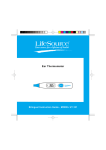
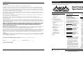
Operating Instruction
Operating Instruction
PRO1100e, PRO1300
Please read and save these instructions. Read carefully before attempting to assemble, install, operate or maintain the product described.
Protect yourself and others by observing all safety information. Failure to comply with instructions could result in personal injury and/or
property damage! Retain instructions for future reference.
WARRANTY
For 5 years from the date of purchase, Wayne Water Systems, d/b/a AquaPro Systems
Heat Pump Pool &
Spa Heater
( "AquaPro" ) will repair or replace, at its option, for the original owner any part or parts of its Heat Pumps (“Product”),
excluding the heat exchanger and compressor, found upon examination by to be defective in materials or workmanship.
For 10 years from the date of purchase, AquaPro will repair or replace, at its option, for the original owner, the Copeland
Scroll compressor, found upon examination by AquaPro to be defective in materials or workmanship. Warranty is limited to
parts only in years 6 through 10 and is on a pro rated basis.
For 15 years from the date of purchase, AquaPro will repair or replace, at its option, for the original owner, the Titanium
Heat Exchanger, found upon examination by AquaPro to be defective in materials or workmanship. Warranty is limited to
parts only in years 6 through 15.
Contents
Please call AquaPro at 1-877-AQUASYS (1-877-278-2797) for instructions. Be prepared to provide the model number and
serial number when exercising this warranty.
Installation Procedures . . . . . . . . . . . .2
Important Safety Instructions . . . . . . .1
Unit Inspection . . . . . . . . . . . . . . . .2
All transportation charges on Products or parts submitted for repair or replacement must be paid by purchaser.
Unit Location . . . . . . . . . . . . . . . . . .2
All non-warranty service charges are the responsibility of the homeowner. Failure to pay for non-warranty service charges
will void this warranty.
Plumbing . . . . . . . . . . . . . . . . . . . . .2
This Limited Warranty does not cover Products which have been damaged as a result of accident, abuse, misuse, neglect,
improper installation, improper maintenance, or failure to operate in accordance with AquaPro's written instructions. All
maintenance and service must be performed by service agents approved by AquaPro Systems. Any unauthorized alteration or
repairs will void this warranty.
THERE IS NO OTHER EXPRESS WARRANTY. IMPLIED WARRANTIES, INCLUDING THOSE OF MERCHANTABILITY AND
FITNESS FOR A PARTICULAR PURPOSE, ARE LIMITED TO ONE YEAR FROM THE DATE OF PURCHASE. THIS IS THE
EXCLUSIVE REMEDY AND ANY LIABILITY FOR ANY AND ALL INDIRECT OR CONSEQUENTIAL DAMAGES OR
EXPENSES WHATSOEVER IS EXCLUDED.
Some states do not allow limitations on how long an implied warranty lasts, or do not allow the exclusions or limitations of
incidental or consequential damages, so the above limitations might not apply to you. This limited warranty gives you
specific legal rights, and you may also have other legal rights which vary from state to state.
In no event, whether as a result of breach of contract warranty, tort (including negligence) or otherwise, shall AquaPro or its
suppliers be liable for any special, consequential, incidental or penal damages including, but not limited to loss of profit or
revenues, loss of use of the products or any associated equipment, damage to associated equipment, cost of capital, cost of
substitute products, facilities, services or replacement power, downtime costs, or claims of buyer’s customers for such
damages.
You MUST retain your purchase receipt along with this form. In the event you need to exercise a warranty claim, you MUST
present a copy of the purchase receipt at the time of service. Please call AquaPro Systems at 1-877-278-2797 for service or
return authorization and instructions.
Basic Heat Pump Operation . . . . . . . .2
Electrical Connections . . . . . . . . . . .2
Connecting to Remote Systems . . .3
Electronic Temperature Controls . . . .4
Description . . . . . . . . . . . . . . . . . . . .4
Buttons . . . . . . . . . . . . . . . . . . . . . . .4
Important Safety
Instructions
Obese persons and persons with a
medical history of heart disease, low
or high blood pressure, circulatory
system problems, or diabetes should
consult a physician before using a
pool or tub.
•
Persons using medication should
consult a physician before using a
pool or tub since some medication
may induce drowsiness while other
medication may affect heart rate,
blood pressure, and circulation.
•
The water in a pool or tub should
never exceed 104ºF (40ºC). A water
temperature in excess of 104ºF is
considered unsafe for all persons.
Lower water temperatures are
recommended for extended use
(exceeding 10-15 minutes) and
young children.
Prolonged immersion in hot water
may induce hyperthermia.
Hyperthermia occurs when the
internal temperature of the body
reaches a level several degrees
above the normal body
temperature of 98.6ºF. The
symptoms of hyperthermia include
dizziness, fainting, drowsiness,
lethargy, and an increase in the
internal temperature of the body.
The effects of hyperthermia include:
unawareness of impending hazard;
failure to perceive heat; failure to
recognize the need to exit pool or
tub; physical inability to exit pool or
tub; fetal damage in pregnant
women; and unconsciousness
resulting in a danger of drowning.
•
Excessive water temperatures have
a high potential for causing fetal
damage during the early months of
pregnancy. Pregnant or possibly
pregnant women should limit pool
or tub water temperatures to 100ºF
(38ºC).
Because the tolerance of water
temperature-regulating devices may
vary as much as ±5ºF (±3ºC), you
should measure the water
temperature at several locations
using an accurate thermometer
before entering a pool or tub.
SAVE THESE INSTRUCTIONS.
This manual contains information that
is very important to know and
understand. This information is
provided for SAFETY and to PREVENT
EQUIPMENT PROBLEMS. To help
recognize this information, observe the
following symbols.
Warning indicates a
hazardous situation which, if not
avoided, could result in death or
serious injury.
Condensation . . . . . . . . . . . . . . . . .5
Pool Blankets . . . . . . . . . . . . . . . . . .5
Seasonal Shutdowns . . . . . . . . . . . .5
Pool Openings . . . . . . . . . . . . . . . . .5
Weather Conditions . . . . . . . . . . . .5
Troubleshooting Guide . . . . . . . . . . . .6
Caution indicates a
potentially
hazardous situation which, if not
avoided, may result in minor or
moderate injury.
!
CAUTION
Notice indicates
important
information, that if not followed, may
cause damage to equipment.
NOTICE
Warranty . . . . . . . . . . . . . . . . . . . . . . . .8
! WARNING
•
DO NOT MAIL THIS FORM TO AQUAPRO SYSTEMS. Use this form only to maintain your records.
MODEL NO.________________ SERIAL NO. _______________ INSTALLATION DATE _______________
ATTACH YOUR RECEIPT HERE
•
CAUTION
•
Water Temperature Set Point . . . .4
Maintenance . . . . . . . . . . . . . . . . . .5
!
Safety Guidelines
! WARNING potentially
Application Guidelines . . . . . . . . . . . .5
Alcohol, drugs, or medication
should not be used before or during
pool or tub use since their use may
lead to unconsciousness with the
possibility of drowning.
READ AND FOLLOW ALL
INSTRUCTIONS.
Mode Selection . . . . . . . . . . . . . . . .4
Diagnostics . . . . . . . . . . . . . . . . . . . .4
•
REMINDER: Keep your dated proof of purchase for warranty purposes! Attach it to this manual or file it for safekeeping.
www.aquaprosystems.com
8
© 2004 AquaPro Systems
For parts, product & service information
visit www.aquaprosystems.com
391503-013 7/04
Operating Instruction
PRO1100e, PRO1300
Installation
Procedures
Unit Inspection
Inspect your unit very carefully before
installing. Make sure there has been no
damage to the evaporator fins or there
are no punctures or oil-soaked areas
on the box. This would indicate
damage to the refrigeration system
and should be rejected immediately.
THE UNIT MUST BE TRANSPORTED
IN THE UP-RIGHT POSITION AT ALL
TIMES AND MUST NOT BE DROPPED
OR TAILGATED. DAMAGE TO THE
UNIT DURING TRANSPORTATION IS
NOT THE RESPONSIBILITY OF THE
MANUFACTURER.
Unit Location
Once the unit has been inspected and
cleared of any transportation damage,
it is now time to locate the pool
heater. It is very important to
understand the location of the unit for
the best performance of operation.
A minimum of 24” of clearance
between the front of the unit (access
panel area) and any obstruction must
be maintained to allow maintenance
on the unit when necessary.
The minimum water circulation
capacity flowing through the pool
heater is 25 gallons per minute and the
maximum capacity is 80 gallons per
minute.
The unit should be located on a solid
level surface, a minimum of 36”x 36”
for proper drainage.
Do not install a water shutoff valve in
the piping from the outlet of the pool
heater to the pool or tub. However, a
check valve that does not include a
shut-off feature may be installed for
convenience during servicing.
Make sure any sprinkler heads are not
directly spraying water on the unit.
While heat pumps are made for an
outdoor environment, they are not
designed to have sprinkler water
constantly spraying them. NOTE: This
type of constant watering directly
on the unit can void your warranty.
Condensation drain holes are provided
in all units for adequate removal of
condensation and rainwater. ALL
UNITS WILL HAVE CONDENSATION.
THIS SHOULD NOT BE MISTAKEN
FOR A LEAK IN THE UNIT.
A minimum of 5’ of vertical clearance
between the top of the unit and any
roof overhang or other obstructions
must be maintained in order to
prevent the re-circulation of cold air
back into the evaporator coils. This is
to maintain the efficiency of the unit.
A check valve or Hartford Loop is
recommended between the unit and a
chlorinator. Failure to do so may void
the warranty.
Figure 1 shows the recommended
installation layout.
Basic Heat Pump
Operation
Electrical Connections
Plumbing
All wiring and
! WARNING electrical
NOTICE
Where freezing weather is
encountered, the detachable
connection/union (provided) must be
utilized immediately adjacent to the
heater to facilitate servicing and
draining of the heat exchanger.
Draining is necessary to prevent
damage to the condenser shell and
coil due to the expansion of
freezing water.
A minimum of 18” of clearance
between the evaporator coils and
shrubs, fences, walls, etc. must be
maintained for adequate air intake.
Notes
connections must be performed by a
qualified electrician. Installations must
be in accordance with local and
national codes.
Overheating, shortcircuiting and fire
damage will result from inadequate
wiring.
!
CAUTION
FILTER
UNIONS
IN
POOL
HEATER
OUT
COLD WATER
IN FROM POOL
CHECK VALVE
CHLORINATOR
WARM WATER
OUTLET TO POOL
Figure 1 - Recommended installation layout
www.aquaprosystems.com
2
7
www.aquaprosystems.com
PRO1100e, PRO1300
Operating Instruction
If a diagnostic code has appeared on
the display, look at the section on the
Electronic Temperature Controller and
see the cause of this code. Once you
have done all that is recommended,
then call the factory for service.
Check the power light. Check to see
if the breaker is set.
•
Make sure the filtration system is on
•
Make sure the thermostat is higher
than the pool water temperature
•
Make sure the filter is clean and is
allowing enough water to flow
•
Make sure the outside ambient
temperature is higher than 50ºF
•
Make sure the 5-minute time delay
has passed
If the unit shuts off when the
thermostat is lowered, it may be
running continuously because it
cannot reach the desired
temperature. A pool blanket may
be required to help reach this
temperature. Also, the filter pump
may need to run longer for the
heater to reach the desired
temperature.
•
CONNECTOR
TEMP
•
•
PUMP
EX
RV
RED
YELLOW
WATER
PRESSURE ORANGE
BLUE
LOW
PRESSURE BLUE
BLACK
HIGH
PRESSURE BLACK
BLACK
BLUE
RED
240V-24V
TRANSFORMER
BROWN
F
BLUE
YELLOW
WP
P4
P1
P3
P2
LP
HP
XFMR
1 3 5 7 9 11
2 4 6 8 10 12
TB1
C
RED
C
COMP
ORANGE
ORANGE
Check the evaporator coil for severe
frost
Unit could be low on refrigerant. At
this point, call the factory for service
and turn off the power to the
heater to keep the cycling from
damaging the compressor.
SENSOR
YELLOW
Check the filters for proper water
flow
H
R
BLACK
S
CAPACITOR
Figure 2
COMPRESSOR
All units are equipped with an electrical wiring
schematic inside the electrical panel. If this is missing,
please contact the factory at 1-877-278-2797 to obtain
one.
All units are to be wired for 230 VAC, 1 phase. This unit
requires a dedicated 50-amp breaker or time delay fuse.
Pool Heater is to be installed in accordance with Article
680 of the National Electrical Code (NEC), NFPA 70, and
within the requirements of all local codes having
jurisdiction.
Unit is running but not heating:
•
WHITE
Unit is cycling:
Unit is running:
•
BROWN/WHITE
LINE LINE
Diagnostic Codes:
BROWN
L2 L1
•
ELECTRONIC
CONTROLLER
FAN
MOTOR
Lower the desired water
temperature below the pool water
temperature. If the unit is still
running, call the factory for service.
BLACK
•
CONTACTOR
If the heater is not operating during
the initial start-up, check to see if it has
been installed properly, per this
owner’s manual. Make sure the breaker
has been sized properly. The following
are conditions to check before calling
Aqua Pro Systems for a service:
Unit runs continuously:
T2 T1
Troubleshooting
Guide
Check the air coming out of the top
of the unit. It should be
approximately 8ºF - 15ºF lower than
the surrounding ambient air
temperature. If not, call the factory
for service.
Connecting to Remote Systems
This Pool Heater is compatible with all known remote
systems in the industry. The following diagram shows
how to connect all of the remote systems to the
Electronic Temperature Controller.
Connection to AquaLink, Compool, Hayward
Remote Systems:
•
Bring two wires (24 VAC) from the remote system to
terminals 11 & 4 on Terminal Block 1 (TB1).
•
Electronic Temperature Control unit must be in the
“Standby” (OFF) mode for the remote system to
operate the Pool Heater.
Connection to Aqua Switch and Intermatic:
•
Bring three wires from the remote system to
Terminal Block 1(TB1):
Terminal 7 = Pool
Figure 3
Terminal 9 = Spa
Terminal 2 = Common
•
www.aquaprosystems.com
6
Electronic Temperature Control unit must be in the
“Standby” (OFF) mode for the remote system to
operate the Pool Heater.
3
www.aquaprosystems.com
Operating Instruction
Mode Selection
Application
Guidelines
Maintenance
Turn on: Press
pool
or
spa
Description
Turn off: Press
pool
or
spa
•
The Electronic Temperature Control
is designed to regulate pool and
spa water temperature.
STAND BY will be displayed by a rolling dot (. . .)
The control has a large threecharacter display for the water
temperature, set points, and
diagnostics. The four-button
keypad includes UP arrow, DOWN
arrow, SPA, and POOL. LED
indicators are used to identify the
pool or spa selection.
Change set points: Press and Hold Temp ▲ or Temp
Pool temp set point range: 70˚F to 98˚F
•
The unit will start up in the
“STANDBY” position from the
factory. The standby position is
represented by a rolling dot (…) on
the display.
Buttons
•
SPA button – Selects the SPA mode
for temperature setting
•
POOL button – Selects the POOL
mode for temperature setting
•
UP button – Increases the
temperature set point
•
DOWN button – Decreases the
temperature set point
•
POWER light – Indicates the unit
has power to the contactor
•
RUN light – Indicates the unit is in
the heating mode
•
SPA light – Indicates the unit is in
the SPA temperature mode
•
POOL light – Indicates the unit is in
the POOL temperature mode
NOTE: The temperature display is in
degrees Fahrenheit and has a display
range of 60ºF to 108ºF for both the
SPA and POOL modes.
Check set points: Press Temp ▲ or Temp
IMPORTANT: Heater will not run without the filter pump
being turned on. Certain conditions cause a
start up time delay. See instruction manual.
25354-001
Spa temp set point range: 70˚F to 104˚F
Figure 4
Water Temperature Set
Point
Temperature set point range is 70ºF to
98ºF for POOL mode and 70ºF to 104ºF
for SPA mode. Pushing the UP arrow or
DOWN arrow buttons will prompt the
control to display the current set point.
Continuing to hold the UP arrow or
DOWN arrow button will allow the set
point values to scroll until the desired
set point is reached. Once the new set
point has been reached, release the
button. The new set point will flash to
indicate the new set point value has
been entered and the display will then
revert back to water temperature as
indicated by a steady display. The
controls have a feature called “Set
Point Memory Retention”. If the power
is removed from the unit, it retains the
last set point displayed.
Diagnostics
The Electronic Temperature Controller
has diagnostic codes, which help
explain any reason for the heater not
to be operating properly. The
following are the diagnostic codes and
the reasons for them appearing:
PS: This code means “Pressure Switch”
or water pressure switch. This
means there is not enough water
flow to activate the water pressure
switch. The cause could be from a
clogged filter or a manual by-pass
is in the wrong position and is not
allowing water into the heater.
Once the filter has been cleaned or
www.aquaprosystems.com
▲
•
(whichever is illuminated)
▲
Electronic
Temperature
Controls
PRO1100e, PRO1300
4
the by-pass has been changed to
allow water to flow through the
heater, the PS display will go away
and the water temperature will
appear on the display.
HP: This code means “High Pressure” or
high pressure switch. Either there is
low water flow or high ambient
temperature or both. Again, the
filter could be clogged and not
allowing enough water flow to
pass through the heat exchanger
and allow the heat to be taken
away fast enough, or a by-pass is
not in the proper position. Once
the filter has been cleaned or the
by-pass has been re-positioned, the
display should return to the
temperature of the water.
LP: This code means “Low Pressure” or
low pressure switch. Either the
outside ambient temperature is too
low for the heater to operate or
the unit is low on refrigerant. If the
outside ambient temperature is
below 50ºF, this could be the
reason for the unit to be in this
mode. Once the outside
temperature has risen above 50ºF,
and the LP code remains, call the
factory for repair.
All heat pumps are designed for
outdoor use. However, some
maintenance is required to maintain
the full life of the heater and is
necessary to maintain your warranty.
Annual maintenance should be
scheduled to make sure blowing sand
or falling debris is removed from the
inside of the heater. Also, rinsing the
coil down, monthly, with low water
pressure will help keep the base of the
unit clear of debris is a must. Do not
use a high pressure washer. This can
cause damage to your evaporator coils
and will void your warranty. It is
recommended that a licensed air
conditioning specialist perform the
annual planned maintenance on your
heater. Call Aqua Pro Systems to have
this scheduled.
If you decide to
rinse down the
evaporator coils yourself, disconnect all
power to the entire equipment pad
before you rinse it. This must be done
in order to prevent possible electrical
shock.
!
CAUTION
Condensation
All heat pump pool heaters will have
condensation. It is typical to have as
much as 6-8 gallons of condensation or
water per hour, during a warm, humid
day. Do not mistake this for a leak.
If you are not sure the water is a leak or
is condensation, there are two ways to
check this. First, use a pool test strip to
see if there is any chlorine or bromine
in the water. If there is, contact the
factory for service. Second, you can turn
off the heater, leave the filter pump
running and see if the water stops. If
you do not see additional water, then
the original water was condensation.
Pool Blankets
Weather Conditions
A pool blanket has been proven to
greatly reduce the heat loss in the pool
and will save as much as 50% - 60% in
your heating bills. During the start of
the swimming season and the end of
the season, if a pool blanket is not
used, the heater may not be able to
maintain your desired temperature
without the use of the blanket.
As might be expected, weather
conditions play a big part in the
operation of the heater. Low outside
ambient temperature, high winds, low
relative humidity, and a large amount
of shading on the pool will all have an
effect on how much time it takes to
heat the pool and how much time it
might need to maintain the desired
temperature. Once the outside ambient
temperature drops below 50ºF, the
heater may not operate.
Seasonal Shutdowns
At the end of your swimming season
you may have freezing weather
conditions. The unions (provided) must
be disconnected to drain any water in
the pipes. You must also drain the heat
exchanger by removing the drain plug
on the side of the unit. This plug can be
removed by pushing in on the collar
while pulling on the plug. Failure to do
so may cause the heat exchanger to
expand and crack. This will void your
warranty.
If you live in an area that does not have
freezing weather conditions but are
subject to extended periods of non-use,
allow the filtration system to continue
to run water through the heater. Or
you can drain the unit of all water.
Pool Openings
If at the end of the previous season you
disconnected the unions, be sure to
connect them before you turn on the
filtration system. Once the pool has
been cleaned and the unit has been
checked for leaks, turn the power on
the heater and set the thermostat to
the desired temperature.
Note: It may take up to three days to
reached the desired temperature
during the opening of the swimming
season. Without a pool blanket, it may
take even longer and may not even
reach the desired temperature until
later in the season.
SF: This code means “Sensor Failure”.
This means the temperature sensor
has either a short or an open and
needs to be replaced. Call the
factory for repair.
5
www.aquaprosystems.com