1
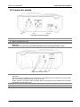
SigmaPAT
MI 3310
Short instructions manual
Version 1.0, Code no. 20 751 705
Distributor:
Manufacturer:
METREL d.d.
Ljubljanska cesta 77
1354 Horjul
Slovenia
E-mail: [email protected]
http://www.metrel.si
© 2010 METREL
Mark on your equipment certifies that this equipment meets the requirements of the EU
(European Union) concerning safety and electromagnetic compatibility regulations
No part of this publication may be reproduced or utilized in any form or by any means
without permission in writing from METREL.
2
MI 3310 SigmaPAT
Table of contents
Table of contents
1
Start-up guide .........................................................................................................4
1.1
Safety and operational considerations ..............................................................4
1.2
Instrument description - Front and connector panel ..........................................5
2.2
Connector panels ..............................................................................................6
1.3
Warnings, messages and symbols....................................................................7
1.3.1
Warnings and messages............................................................................7
1.3.2
Warning symbols and other symbols........................................................10
1.3.3
PASS /FAIL indication ..............................................................................10
1.3.4
Battery and mains supply indication .........................................................11
1.3.5
Bluetooth indication (optional) ..................................................................11
1.4
Battery handling ..............................................................................................12
1.5
Warranty & Repairs .........................................................................................12
1.6
Contact Metrel UK ...........................................................................................14
2
Quick-test guide ...................................................................................................15
2.1
Instrument test modes .....................................................................................15
2.2
Carrying out a Shortcut autotest sequences....................................................16
2.3
Carrying out a Custom autotest.......................................................................17
2.4
Carrying out a Project autotest ........................................................................18
2.5
Measurements.................................................................................................19
2.5.1
Earth Bond ...............................................................................................19
2.5.2
Insulation resistance.................................................................................20
2.5.3
Insulation-S resistance .............................................................................21
2.5.4
Substitute leakage....................................................................................22
2.5.5
Substitute leakage-S current ....................................................................23
2.5.6
Differential leakage current ......................................................................24
2.5.7
Touch leakage current..............................................................................25
2.5.8
(Active) Polarity ........................................................................................26
2.5.9
TRMS current (using current clamp adapter) ...........................................27
2.5.10 PRCD / RCD testing.................................................................................28
2.5.11 Power / functional test ..............................................................................29
3
Step by step PC SW installation..........................................................................30
3
MI 3310 SigmaPAT
Start-up guide
1 Start-up guide
1.1 Safety and operational considerations
Ì
This document is a supplement to the Instruction manual!
Ì
Warning on the instrument means »Read the Instruction manual with special
care to safety operation«. The symbol requires an action!
Ì
Read the Instruction manual carefully, otherwise use of the instrument may be
dangerous for the operator, for the instrument or for the equipment under test!
Ì
If the test equipment is used in manner not specified in this user manual the
protection provided by the equipment may be impaired!
Ì
Do not use the instrument and accessories if any damage is noticed!
Ì
Consider all generally known precautions in order to avoid risk of electric shock
while dealing with hazardous voltages!
Ì
Do not use the instrument in supply systems with voltages higher than CAT II
300 V!
Ì
Use only correctly earthed mains outlets to supply the instrument!
Ì
Use only standard or optional test accessories, supplied by your distributor!
Ì
Instrument servicing and adjustment is only allowed to be carried out by a
competent authorized personnel!
Ì
In case a fuse has blown follow the instructions in user manual to replace it!
Ì
Hazardous voltages can exist inside the instrument. Disconnect all test leads,
remove the power supply cable and switch off the instrument before opening the
battery compartment.
Ì
Instrument contains rechargeable Ni-Cd or Ni-MH battery cells. The cells should
only be replaced with the same type as defined on the battery placement label or
in this manual. Do not use standard alkaline battery cells while power supply
adapter is connected, otherwise they may explode!
Ì
If a test code with an earth bond test current not supported by the instrument is
selected the SigmaPAT instrument will automatically perform the earth bond test
with lower test current (200 mA or 10 A). The operator must be competent to
decide if performing the test with lower test current is acceptable!
Ì
It is advisable not to run tested devices with load currents above 13 A for more
than 15 minutes. Load currents higher than 13 A can result in high temperatures
of main supply connector and fuse holders!
4
MI 3310 SigmaPAT
Instrument description
1.2 Instrument description - Front and connector panel
Front panel
1
2
3
4
5
6
7
8
9
10
11
12
13
240 × 128 dots graphic matrix display with backlight
Function keys intended for displayed defined options.
ESCAPE key
HELP key
ON / OFF key
Cursor keys and ENTER key
SEND key
START / STOP key
Test probe EB/S, used as output for erath bond test and probe input in for class 2 equipment tests
(insulation resistance – S, substitute leakage – S, and touch leakage currents).
Alpha-numeric keyboard
LN and PE sockets for testing the insulation resistance and substitute leakage current of fixed
installed DUTs.
Warning!
These sockets are intended only for the connection to deenergized devices.
Test socket
Warning!
Dangerous voltage is present on the test socket during the measurement. Maximum output current
is 16 A, test only devices with maximum rated supply current not higher than 16 A!
Note: For devices incorporated high reactive loading, e.g. motor with rated power > 1.5 kW, it is
recommended to start measurement first and to turn on the tested device later.
IEC appliance connector for testing supply cords
Warning!
The connector input is for test purpose only; do not connect it to the mains supply!
5
MI 3310 SigmaPAT
Instrument description
2.2 Connector panels
Left side connector panel
14
15
16
17
Two T16 A / 250 V fuses for instrument protection
Mains supply connector
Battery compartment cover
Fastening screw for battery compartment cover
Warning!
Disconnect all accessory and tested equipment before opening the battery cover!
Right side connector panel
18
19
20
21
Current clamp adapter input sockets
Warnings!
Do not connect any voltage source on this input. It is intended only for connection of current clamp
with current output. Maximum input current is 30 mA!
Green socket is connected to the functional earth of the system and is intended for connection
with shield of current clamp only.
USB connector
Barcode reader connector
PC / PRINTER connector
6
MI 3310 SigmaPAT
Instrument description
1.3 Warnings, messages and symbols
1.3.1 Warnings and messages
Mains voltage is not
correct or PE not
connected.
Check mains voltage
and PE connection!
Warning for improper supply voltage condition. Possible
causes:
- No earth connection or other wiring problem on
supply socket.
- Incorrect mains voltage.
Determine and eliminate the problem before proceeding!
Warning:
- The instrument must be earthed properly!
Warning!
Instrument is
connected to an IT
earthing system or PE
not connected.
Supply voltage warning. Possible causes:
- No earth connection,
- Instrument connected to an IT earthing system.
Warning:
- The instrument must be earthed properly!
No mains voltage.
Connect PAT to mains
voltage.
Instrument not connected to the mains supply voltage.
For some measurements like differential / touch leakage
tests, PRCD / RCD tests and active polarity, operating the
instrument from mains voltage is required.
Connect the instrument to the mains voltage and start
selected test again.
L – N resistance too
high (>30 kΩ)!
Check fuse and
switch.
Are you sure to
proceed (Y/N)?
An excessively high resistance was measured in the fuse
pre-test. Indication means that tested device has too low
consumption or is:
- Not connected,
- Switched off,
- Contains a fuse that has blown.
Select YES or NO with Y or N key.
Resistance L – N low!
Are you sure to
proceed (Y/N)?
A low resistance of the device under test (DUT) supply input
was measured in the pre-test. This means that it is very
likely that an excessively high current will flow after applying
power to the DUT. If the high current is only of short duration
(caused by a short inrush current) the test can be performed,
otherwise not.
Select YES or NO with Y or N key.
7
MI 3310 SigmaPAT
Resistance L – N too
low!
Are you sure to
proceed (Y/N)?
Leakage LN-PE high!
Are you sure to
proceed (Y/N)?
Leakage LN-PE too
high!
Are you sure to
proceed (Y/N)?
Leakage LN-PE or
EB/S too high!
Are you sure to
proceed (Y/N)?
Instrument description
An extremely low resistance of the DUT supply input was
measured in the pre-test. It is likely that fuses will blow after
applying power to the DUT. If the too high current is only of
short duration (caused by a short inrush current) the test can
be performed otherwise it must be stopped.
Select YES or NO with Y or N key.
It is recommended to additionally check the DUT before
proceeding with the test!
Dangerous leakage current (higher than 3.5 mA) will flow if
power would be connected to DUT.
Select YES or NO with Y or N key.
Proceed with testing only if all safety measures have been
taken. It is recommended to perform a thorough earth bond
test on the PE of the DUT before proceeding with the test.
Dangerous leakage current (higher than 20 mA) will flow if
power would be connected to the DUT.
Determine and eliminate the problem before proceeding!
Dangerous leakage current (higher than 20 mA) would flow if
power were connected to the DUT.
Select YES or NO with Y or N key.
Proceed with testing only if all safety measures have been
taken.
It is recommended to perform a thorough earth bond test on
the PE of the DUT before proceeding with the test.
External voltage on
test socket too high!
DANGER!
- Voltage on mains test socket or LN/PE terminals
is higher than approximately 25 V (AC or DC)!
Disconnect the DUT from the instrument immediately and
determine why external voltage was detected!
External voltage on
EB/S too high!
DANGER!
- Voltage on test probe (EB/S) is higher than
approximately 25 V (AC or DC)!
Disconnect the test probe from the DUT and determine why
external voltage was detected!
Test was skipped for
safety!
Instrument skipped the required test because of a failed
previous test.
8
MI 3310 SigmaPAT
Overheated!
Warning!
More than 80 % of
memory is occupied.
Stored data should be
downloaded to PC.
Warning!
Calibration has been
expired.
Instrument description
Temperature of internal components of the instrument
reached their top limit. Measurement is prohibited until the
internal temperature has reduced.
Instrument memory is almost full. Download stored results to
PC.
Recalibration of the instrument is required. Contact your
dealer.
Measurement aborted,
contact voltage too
high (> 50V).
A too high contact voltage was detected before an RCD test
being carried out. Check PE connections!
Hardware error.
Return the instrument
to the repair centre.
The instrument detects a serious failure.
9
MI 3310 SigmaPAT
Instrument description
1.3.2 Warning symbols and other symbols
Remove the EB/S connection, especially if it is connected to
any part that will begin to rotate or move when power is
applied.
Connect the test lead to the EB/S test socket.
Warning!
A high voltage is / will be present on the instrument output!
(Insulation test voltage, or mains voltage).
The DUT should be switched on (to ensure that the complete
circuit is tested).
Connect the lead to be tested to the IEC test terminal.
Connect current clamp adapter in this test.
1.3.3 PASS /FAIL indication
Test passed.
Test failed.
Some tests in the autotest sequence were skipped, but all
performed tests passed.
10
MI 3310 SigmaPAT
Instrument description
1.3.4 Battery and mains supply indication
Battery capacity indication.
Low battery! Battery is too weak to guarantee correct result.
Replace or recharge battery cells.
Instrument connected to the mains supply voltage. When
instrument is in idle mode recharging process is in progress.
Recharging in progress (if instrument is connected to the
mains supply voltage).
1.3.5 Bluetooth indication (optional)
Bluetooth communication is enabled. Remote device (printer
or barcode reader) can now be connected with the
instrument.
Remote Bluetooth device (printer or barcode reader) is
connected with the instrument.
Searching for Bluetooth devices or connecting procedure
with the selected Bluetooth device (printer or barcode
reader).
11
MI 3310 SigmaPAT
Start-up guide
1.4 Battery handling
Ì
Ì
Ì
Ì
When replacing battery cells or before opening battery/fuse compartment cover,
disconnect any test leads/accessory connected to the instrument and switch off
the instrument. Hazardous voltage can exist inside the instrument!
Insert all cells correctly! If this is not performed correctly, the instrument will not
operate and the battery could be discharged.
If the instrument is not used for a long period of time, remove all of the battery
from the battery compartment to protect the instrument from leakage.
Alkaline or rechargeable Ni-MH battery cells (size C) can be used. The operating
hours are given for cells with a nominal capacity of 4500 mAh.
Do not recharge alkaline battery cells! The battery will begin charging as soon as the
instrument is connected to the mains supplv voltage. The in-built protection circuits
control the charging procedure.
Battery charging symbols
Note:
Ì Only use the power supply adapter delivered from manufacturer or distributor of
the test equipment to avoid possible fire or electric shock!
1.5 Warranty & Repairs
Metrel UK’s instruments have a three year warranty against defects in materials or
workmanship. Accessories and other supplementary products have a one year warranty
against defects in material or workmanship.
Any potentially defective items should be returned to Metrel accompanied by
information regarding the faults that was incurred. It is recommended that any defective
equipment is sent back to Metrel via the wholesaler from which the product was
purchased.
All defective products will be replaced or repaired within policy period. For these
items, a full refund will only be issued if a sufficient replacement is not available. Any
shipping / return-shipping costs are not refundable.
Metrel UK shall not be held liable for any loss or damage resulting from the use or
performance of the products. In no event shall Metrel UK be liable to the customer
or its customers for any special, indirect, incidental, exemplary or punitive damages
resulting from loss of use, interruption of business or loss of profits, even if Metrel UK
has been advised of the possibility of such damages.
If the customer’s unit is out of warranty but needs repairs a quote for repair will be
provided via the wholesaler through which the instrument was sent in.
Notes:
Ì Any unauthorized repair or calibration of the instrument will infringe the product’s
warranty.
Ì All sales are subject to Metrel UK’s Standard Terms and Conditions, a full copy
of which is available Metrel UK’s office. Metrel UK reserves the right to change
the conditions at any time. Any typographical, clerical or other error or omission
in any sales literature, quotation, price list, acceptance of offer, invoice or other
12
MI 3310 SigmaPAT
Ì
Ì
Ì
Ì
Start-up guide
documentation or information issued by Metrel UK shall be subject to correction
without any liability on the part of the customer.
Specifications and designs of goods are subject to change by Metrel UK at any
time without notice to the customer. Metrel UK reserves the right to make any
changes in the specification of goods which are required to conform with any
applicable statutory or EC requirements or, where goods are to be supplied to
Metrel UK’s specification, which do not materially affect their quality or
performance.
If a condition was found to be invalid or void it would not affect the overall validity
of the remainder of the conditions;
Metrel UK are excluded from liability for any delays or failure to comply, where
the reason is beyond Metrel UK’s control;
No order which has been accepted by Metrel UK may be cancelled by the
customer except with the agreement in writing of Metrel UK and on terms that the
customer shall indemnify Metrel UK in full against all loss (including loss of
profit), costs (including the cost of all labour and materials used), damages,
charges and expenses incurred by Metrel UK as a result of cancellation. The
minimum charge for such cancellation will be 25 % of the total value of the goods
ordered.
13
MI 3310 SigmaPAT
Start-up guide
1.6 Contact Metrel UK
Metrel UK
Unit 1, Hopton House, Ripley Drive
Normanton Industrial Estate
Normanton,
West Yorkshire
WF6 1QT
Tel.:+44/ (0) 1924 24 50 00
Fax: +44/(0) 1924 24 50 07
E-mail: [email protected]
Web: www.metrel.co.uk
Update your meter
Metrel offers a service of updating your software of firmware to the latest developments.
Register on www.metrel.co.uk to receive updates of PC SW and firmware of the meters.
Calibrate your Meter
Metrel offers a calibration service of all Metrel equipment. Contact Metrel UK on 01924
245000 and ask for the calibrations department.
Repair
Metrel offers a repair service of all Metrel equipment. Contact Metrel UK on 01924
245000 and ask for the repairs department.
Ask a technical question
Metrel offers a Technical Advice Line every Mon-Thu from 8:00 a.m. till 5.00 p.m. and
Fridays from 8:00 a.m. till 4 p.m..
Get training on Metrel meters
Metrel offers training on site or at the office subject to a charge.
14
MI 3310 SigmaPAT
Quick-test guide
2 Quick-test guide
2.1 Instrument test modes
Instrument has there operation modes.
<AUTOTEST SHORTCUT>, a group of pre-defined auto sequences, suitable for
working with barcodes;
<AUTOTEST CUSTOM>, a group of user defined pre-programmed auto sequences;
<PROJECT AUTOTEST> a group of stored data for re-use;
<SINGLE TEST>, individual tests;
<USER/APPLIANCE DATA>, lists of user and appliance data;
<RECALL/DELETE/SEND RESULTS>, manipulation with stored data;
<DATA UPLOAD/DOWNLOAD>, upload/download different data from PC to the
instrument (stored test results, list of default DUT and test site names, list of
custom auto-sequences);
<SETUP> the menu for general settings of the instrument.
15
MI 3310 SigmaPAT
Start-up guide
2.2 Carrying out a Shortcut autotest sequences
1
Set function
2
Set appliance type and protective measures
In Main menu select AUTOTEST SHORTCUT.
3
Carry out Shortcut autotest sequence
Before test view test parameters and limits.
4
Save and view results
After Shortcut test sequence is finished Save result
menu is displayed.
16
MI 3310 SigmaPAT
Quick-test guide
2.3 Carrying out a Custom autotest
1
Set function
2
Select appropriate autotest sequence
In Main menu select AUTOTEST CUSTOM.
3
Carry out Custom autotest sequence
Before test set parameters and limits (if
applicable).
4
Save and view results
After test sequence is finished Save result menu is
displayed.
17
MI 3310 SigmaPAT
Start-up guide
2.4 Carrying out a Project autotest
1
Set function
2
Search appropriate sequence
In Main menu select PROJECT AUTOTEST.
3
Select and carry out Project autotest
sequence
4
Save, view and compare results
After test sequence is finished Save result menu is
displayed.
18
MI 3310 SigmaPAT
Quick-test guide
2.5 Measurements
2.5.1 Earth Bond
1
2
Set function
Set parameters and limits
Output
Limit
Time
3
5
Nominal test current
Maximum earth bond resistance
Test time
4
Test circuit for Earth Bond test
View results
19
Carry out the test.
MI 3310 SigmaPAT
Start-up guide
2.5.2 Insulation resistance
1
2
Set function
Set parameters and limits
Output
Limit
Time
3
5
Nominal test voltage
Minimum insulation resistance
Test time
4
Test circuit for Insulation test
View results
20
Carry out the test
MI 3310 SigmaPAT
Start-up guide
2.5.3 Insulation-S resistance
1
2
Set function
Set parameters and limits
Output Nominal test voltage
Minimum insulation resistance
Limit
Test time
Time
3
5
4
Test circuit for Insulation-S test
View results
21
Carry out the test
MI 3310 SigmaPAT
Start-up guide
2.5.4 Substitute leakage
1
2
Set function
Set parameters and limits
Limit
Time
3
5
Maximum sub leakage current
Test time
4
Test circuit for Substitute leakage test
View results
22
Carry out the test
MI 3310 SigmaPAT
Start-up guide
2.5.5 Substitute leakage-S current
1
2
Set function
Set parameters and limits
Limit
Time
3
5
Maximum sub leakage current
Test time
4
Test circuit for Substitute leakage-S test
View results
23
Carry out the test
MI 3310 SigmaPAT
Start-up guide
2.5.6 Differential leakage current
1
2
Set function
Set parameters and limits
Limit
Time
3
5
Maximum differential leakage current
Test time
4
Test circuit for differential leakage test
View results
24
Carry out the test
MI 3310 SigmaPAT
Start-up guide
2.5.7 Touch leakage current
1
2
Set function
Set parameters and limits
Limit
Time
3
5
Maximum touch leakage current
Test time
4
Test circuit for touch leakage test
View results
25
Carry out the test
MI 3310 SigmaPAT
Start-up guide
2.5.8 (Active) Polarity
1
2
Set function
Set parameters and limits
Test Type of polarity test
3
Test circuit for polarity test
Polarity test – normal for IEC cord
4
Polarity test - active for RCD protected cord
5
Carry out the test
26
View results
MI 3310 SigmaPAT
Start-up guide
2.5.9 TRMS current (using current clamp adapter)
1
2
Set function
Set parameters and limits
Limit
Time
3
5
Maximum current
Test time
Test circuit for TRMS current test using current clamp adapter
View results
27
4
Carry out
the test
MI 3310 SigmaPAT
2.5.10
1
Start-up guide
PRCD / RCD testing
2
Set function
Set parameters
Test
Idn
Multi
Phase
Mode
3
Test circuit for RCD / PRCD test
Testing of standard RCD
4
5
Type of residual current device
Nominal test current
Actual test current
Starting angle
Type of PRCD/RCD test
Testing of portable RCD (PRCD)
Carry out the test
View results
28
MI 3310 SigmaPAT
2.5.11
1
Start-up guide
Power / functional test
2
Set function
Set parameter
Time
3
5
4
Test circuit for power / functional test
View results
29
Test time
Carry out the test
MI 3310 SigmaPAT
Step by step PC SW instalation
3 Step by step PC SW installation
PATLink PRO and PATLink PRO Plus
Important: The user should have full administrative privileges, in the case of Windows
7 is installed on you computer. Read the document in section Installing instructions Æ
privileges troubleshooting on windows 7
1. Insert a CD delivered with the instrument into the CD/DVD drive of your computer.
2. The software should automatically run. If this is not the case, double click on the
CD/DVD drive icon on your computer to open the contents of the CD and double click
on the “METREL.exe” program file.
3. The initial welcome screen will appear, select the language, area location and and
product name.
Language selection
30
MI 3310 SigmaPAT
Start-up guide
Area selection
Product name selection
4. To install the software, Select PATLink PRO in the next screen
31
MI 3310 SigmaPAT
Start-up guide
Product section
5. The installation of the software will now begin, on the welcome screen select »Next«
and follow the setup instructions
6. After completing the installation, confirm finishing the installation leave the check box
ticked to automatically start the program (a shortcut is automatically placed on the
desktop and in the start menu for future software initiations).
7. To start PATLink PRO software, click the shortcut on the dektop or in the start menu
Help files are available on the software to guide you through the various sections of the
software.
8. Select “Installing USB”.
Read carefully Installing USB instruction manual available on CD and follow the
instruction on how to establish connection between instrument and PC and download
the data.
The USB drivers will be automatically installed on the windows 7 OS.
32