1
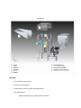
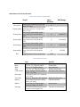
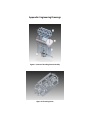
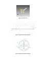
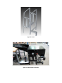
Thresher User Manual Ohio University Russ College of Engineering Mechanical Engineering: Team Captain Plant-It & Appalachian Staple Food Collaborative 6/1/2010 User Manual FEATURES Fully enclosed threshing area Guards over moving parts Flexible frame and construction with bolt on parts Two access points o Output that folds up to provide access to the drum o Concave that lowers to provide access to itself and the drum. Variable pitch pulleys and various pulley combinations that allow for a wide range of crop capability. 4‐Stroke Internal combustion gasoline engine for power in ultimate location flexibility. Painted surfaces to discourage the formation of rust. SAFETY Warning: Captain Plant It thresher contains an Internal Combustion Gasoline engine. This engine contains hazardous chemicals, toxic fumes and hot surfaces that could cause harm or even death. The engine also contain flammable chemical that could result in a fire or even an explosion. For the complete overview of all warnings and risks please consult the engine manual. Warning: The Captain Plant It thresher contains moving parts that could cause serious harm or even death if anything is caught in the moving drum or in the belt system. While in operation: All guards should be in place and all adjustment bolts should be tightened down. The output should always be in the down position. There is NO reason why it should be in the upright position. While loading, the loader’s hand should never come close to the opening at the end of the input. If the crop gets stuck on the input or output turn off the thresher and only proceed when it is completely stopped. It is recommended that anyone with long hair working on or with the thresher put up their hair or where a hat in order to reduce that risk of their hair being caught in the belt or on the drum. This could result in very serious injuries. In adjustment or maintenance mode: Ensure that the motor throttle in set in its off position and it is recommended that the spark plug wire be disconnected and kept away from the spark plug. Be careful around the motor it may be hot. It is recommended that anyone with long hair working on or with the thresher put up their hair or where a hat in order to reduce that risk of their hair being caught in the belt or on the drum. It is recommended that the user not use gloves when adjusting the thresher as they could get caught and that could result in an injury. Warning: Never start the machine if anything is inside of the threshing area. This could result in injury or damage to the thresher. Caution: Various parts of the Captain Plant It thresher may get hot during operation. Caution is recommended after prolonged usage. Caution: Do not over lift the concave. This could result in the drum hitting the concave and broken parts. There is a chance of flying parts that could result serious injury. One should always spin the drum by hand before operation to insure that the drum will not hit the concave and all concave adjustment points should be tight. Caution: When the output is in the upright position it could easily fall and cause injury to any one below it. It should be tied down to make sure this does not occur. Caution: When working on or with thresher beware of any pinch points or sharp edges as one could get hurt. OPERATION Starting and Running the Thresher 1) Ensure that all the security knobs on the concave are tightened down and the concave is snug. 2) Rotate the threshing drum by hand to make sure that there are no restrictions to rotation. 3) Slide the idler pulley up on the slide to tension the belt (remember to only tension the slack side of the belt) and make sure that the belt is seated properly in all pulleys and is not rubbing on anything. All set screws on the pulley should be tightened and the nuts on the idler should be wrench tightened. Table 1: Recommended V‐Belt Tensioning (from Bando USA) V‐belt A Small Sheave Diameter (Inches) < 3.0 Initial instillation 3.6 lbs Re‐tensioning Maximum 3.1 lbs Re‐tensioning Minimum 2.4 lbs 4) Replace the belt cover and ensure that the output is in the down right position. 5) Set the engine throttle to the desired speed, set the chock if needed and pull start the engine. For further instructions for starting the engine please consult the engine manual. Notice: Ensure that the engine is filled with oil before you start the engine, instructions to do so can be found in the engines user manual. Running the motor without oil can result in damage to the engine. 6) Load reaped crop in to the input and allow it to slide down the ramp. Never reach your hand in to the threshing area or attempt to throw crop into the threshing area. Notice: The inside surfaces are not painted and are unprotected, they may develop rust. Threshing wet or moist crop is not recommended. 7) Collect threshed grain in container at the end of the output. Adjusting and Changing Thresher Settings to Change Crops 1) Make sure that the engine is completely off, the throttle in all the way in the off position. One could remove the spark plug wire just to be safe. 2) Guarantee that all the concave security knobs are loose before cranking down the jack and raise or lower the concave to the desired level. 3) When the thresher is off the output can be raised or lower at anytime to gain access to the threshing area. If working under the output then it should be tied down to make sure it doesn’t fall. 4) When adjusting pulley system the engine must be off. The drum pulley can be removed and replaced with different sized pulleys by and the engine variable pitch pulley can be adjusted by loosening the set screw and spinning half of the pulley. Ensure that all set screws are tight before starting the thresher and make sure to tighten the belt with the idler and tightened the nuts. Table 2: Recommended Threshing Settings for Given Crops Crop Buckwheat Spelt Amaranth Millet Black eye beans Azuki beans Oats RPMs* Min 1375 2150 # 2150 550 550 2150 Max 1850 2475 # 2475 1225 1225 2475 Concave Distances^ 3/8’’‐5/8’’ 3/8’’‐5/8’’ ¼’’‐½’’ ¼’’‐½’’ 3/8’’‐5/8’’ # 3/8’’‐5/8’’ *RPM are approximate and were converted from the Allis‐Chambers All Crop Model 66 where the d all crop is 15 crop chart using the equation inches, d cp thresher is 9.75 inches and RPM all crop is found from the chart in the Allis Chambers manual #These values are yet to be determined by testing by Joseph Schultheis ^The concave distances are from the Allis‐Chambers All Crop Model 66 manual MAINTENANCE Scheduled Maintenance 1) Motor (Check engine manual for detailed instructions) a. Daily i. Check Engine oil ii. Clean area around muffler, controls and finger guard b. Every 25 hours i. Clean air filter ii. Clean pre‐cleaner c. Annually i. Change engine oil ii. Check muffler and spark arrester iii. Replace air filter iv. Replace spark plug v. Clean air cooling system Note: Fuel can become stale when stored over 30 days. It is recommend that one add fuel stabilizer or empty the tank. 2) Belts a. Weekly i. Inspect belt for wear. If wear is excessive then it should be replaced. ii. Clean belt. Keep dust and chemicals off of belt. Never clean the belt with oils or chemicals unless they are approved by the belt manufacturer 3) Bearings a. Daily/Weekly i. Inspect bearings, make sure they are not making excessive noise and the drum spins freely with the belt is not attached. Note: Bearings are self contained and do not need lubricated. 4) Paint condition/Rust a. Weekly/Monthly i. Inspect all painted surfaces inside and out. Surface rust can be removed and repainted. If rust is on the inside of the concave, the drum or any working surfaces, then remove the rust and apply rust resistant clear coat. Troubleshooting I. Problem: Excessive vibration Solution Check security knobs on the concave and ensure that they are all tightened. If not stop engine if you have not already and tighten the knobs. Ensure that thresher is bolted down tightly with rubber mounts. Check vibration rubber mounts under engine and scissor jack. Check all bolts and tighten them with the engine off. Check pulleys and belt system. Check drum and bearings. II. Problem: Under threshing crop or over threshing crop Solution If under‐threshed (not removing seed) speed up drum and/or decrease distance between drum and concave. For over threshing (breaking shell or seed or pulverizing seed) slow down threshing drum. III. Could also add rubber to rasp bars or remove up to four rasp bars. Note: Only remove rasp bars in even number increments to maintain balance. Problem: Hot Bearings Solution Drive under tensioned and belts are slipping causing heat build‐up then re‐tension belt. The drive is over tensioned with belts bottoming out then the pulleys are worn and should be replaced. Bad bearings because of poor maintenance or under‐design. Replace bearings and evaluate maintenance or bearing might need redesigned. Pulleys too far out on shaft pull them in as far as possible. IV. Problem: Belt deterioration or breaking prematurely (Check belt or pulley manufacture’s catalog for full detailed list.) Solution Check for foreign objects in the drive, make sure that the guard is installed or make sure that the belt drive is protected. Check for oil or grease on belts. Clean belts and sheaves with a degreasing agent or detergent and water and remove the source of oil or grease Excessive slippage, re‐tension belt. Check sheave or pulley grooves for wear of damage, replace pulley if needed. IV. Problem: Threshing drum is not spinning or rotating correctly. Solution Check belt drive and ensure that the belt is correctly tensioned and not slipping. Check the drum and make sure that the shear pins are not broken (they are located in the two collars on both outside aluminum spoked wheels). Check that all the pulleys are tightly connected to the shafts and the keys are not broken. Check the engine and ensure that is not broken and is transmitting power. How to: HOW TO REPLACE SHEAR PINS 1) Locate collars on the two outside aluminum wheels on the drum. 2) Remove both set screws in the collars. 3) Using a punch remove parts of the shear pin in the shaft and the collar. 4) Replace the shear pin. One should not have to force the new shear pin in. 5) Replace both set screws. 6) Repeat in other side. Note: Both shear pins should always be replace together whether or not both are broken. HOW TO TENSION BELTS 1) To tension belts, adjust the idler pulley until the belts appear fairly taut. When struck with the hand, belts will bounce back with a springy motion. 2) Run the drive for about 15 minutes to seat the belts, and apply full load. If the belts slip or squeal, apply more tension. When the drive is in motion, a slight sag on the slack side is normal. 3) An alternate method of tensioning is to use the simplified force/deflection method, as follows(as described by belt manufacture Bando USA): a. Measure the span length, L of the belt drive. b. At the center of the span, apply a force perpendicular to the belt. Measure the force required to deflect the belt 1/64” per inch of span length. For example, for a 100” span, the deflection would be 100/64, or approximately 1 1/2” inches. c. Tighten or loosen the belt to bring it into the correct range. d. When you install new belts, tighten them to “initial tension” forces shown in the tables. This tension will drop during the run‐in period. HOW TO INSTALL NEW BELTS AND ADJUST THE SLACK 1) Always shorten the center distance of the drive by adjusting the idler pulley, until the belts can be laid over the sheaves. 2) Never pry or force a belt on the drive with a pry bar or by cranking. This will almost certainly damage the tensile cord and although the injury may not be visible, belt life will be drastically reduced. 3) Work the belts by hand to move slack so it is on the same side — top or bottom — or all belts. This assures all belts start under equal strain. 4) Re‐tension the idler until the belt is seated in the grooves and the slack is taken up. Replacement Part Charts and Details Table 3: Belt system parts and RPM ranges Detail Outer diameter Nylon V‐belt, A belt type, 3’’OD, 3/8’’ wide, 3/8’’ bore Cast iron variable pitch V‐belt pulley, Engine pulley A belt type, ¾ bore, 3.15’’OD, Pitch dia. 1.9’’‐2.9’’ Zinc die cast V‐belt pulley, A belt Drum pulley type, 3’’OD, 5/8’’ bore, Pitch Dia. 2.75’’ Zinc die cast V‐belt pulley, A belt Drum pulley type, 4’’OD, 5/8’’ bore, Pitch Dia. 3.75’’ Zinc die cast V‐belt pulley, A belt Drum pulley type, 6’’OD, 5/8’’ bore, Pitch Dia. 5.75’’ Zinc die cast V‐belt pulley, A belt Drum pulley type, 9’’OD, 5/8’’ bore, Pitch Dia. 8.75’’ Belt Cogged rubber V‐belt, A section belt Idler pulley RPM Range 3’’ ‐ 3.15’’ ‐ 3’’ 1658‐2351 4’’ 1216‐1856 6’’ 793‐1210 9’’ 521‐795 TBD ‐ Table 4: Replacement Parts Size Details Bolts Bolts Bolts Bolts Collar screws ¼’’‐20, 1.5’’ long zinc plated 3/8’’‐16, 1.5’’ long zinc plated #6‐32, 1.5’’ long zinc plated 5/16’’‐24, 1.5’’ long zinc plated Flat 82˚ Phillips head zinc‐plated ¼’’‐20, 1 ½’’ long 416 Stainless Steel 5/32’’ diameter, 1 1/4 ’’ long ¼’’‐28 ¼’’ long with 1/8’’ hex head 70A durometer Neoprene Spring rubber 3/8’’ thick 70A durometer Ultra Strength Neoprene rubber 3/8’’ thick Base mount ball bearing steel, 5/8’’ diameter, center height 7/8’’ Sheet metal bolts Frame Bolts Rasp Bar bolts Bearing mount bolts To connect the collars to Shear pins Set screws Rubber Rubber Bearings Collars for shear pins Vibration mounts Concave bars Thresher Drum bearings Appendix: Engineering Drawings Figure 1: Concave Threshing Drum Assembly Figure 2: Threshing Drum Figure 3: Collar‐Shear Pin Figure 4: Engineering Drawing of the Shaft Figure 5: Engineering Drawing of the Wheel Figure 6: Frame Figure 7: Captain Plant It Thresher


![DGID Software [EN]](http://vs1.manualzilla.com/store/data/005717670_1-65b44a14cec330296683d17d94da3fca-150x150.png)