1
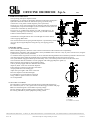
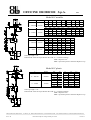
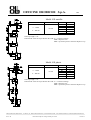
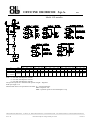
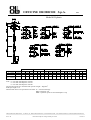
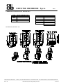
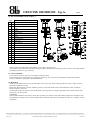
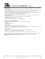
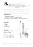
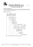
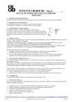
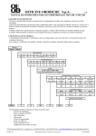
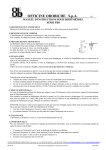
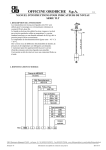
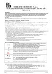
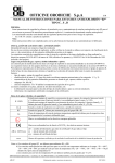
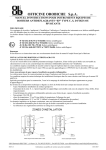
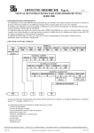
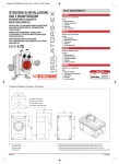
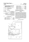
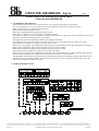
OFFICINE OROBICHE S.p.A.
1/13
USER’S MANUAL FOR LEVEL SWITCHES
of the electrical SERIES 40
1. INSTRUMENT DESCRIPTION
The instruments of the 40 series are positive buoyancy level switches for mounting on vessel head.
They are equipped with various switching units to provide independent alarm and/or signalling contacts.
Model 41A provides a low or high-level alarm contact.
Model 41B is designed for pump control.
Model 41C is equipped with two independent alarm contacts.
Model 41D/1 is designed to control two pumps, of different capacity.
For instance, to allow a vessel to remain full, if the level lowers, the first (small) pump will be actuated, but if the level
continues to fall, the second (large) pump will be started.
The large pump will be started and stops under the small pump’s threshold.
The instrument can even be used to keep a tank empty, in which case the operation of the two pumps is reversed.
Even model 41D/2 manages two pumps. It is used to drain a vessel.
In this case, the two pumps start at different levels but both only switch off after the level has reached the lower displacer.
Model 41D/3 combines the pump start and stop functions with a low-level alarm.
Model 41D/4 combines the pump start and stop function with a high-level alarm.
The instrument 41D/5 manages two pumps. It is only used to fill a tank.
In this case, the two pumps start at different levels but both only switch off after the level has reached the upper displacer.
The instruments are designed to be mounted on top of pressure vessels, in a vertical position.
The adjustment of the operation points takes place by adjusting the position of the displacers along the instrument’s rope.
The models can be equipped with SPDT or DPDT exchange contacts for a low or high-level control and/or alarm; the
contacts can be electric or pneumatic in type.
2. MODEL IDENTIFICATION
24010 Ponteranica (BG) ITALY - via Serena, 10 - Tel. 0039/035/4530211 - Fax 0039/035/570546 - www.officineorobiche.it-e-mail:[email protected]
**********************************************************************************************************************************************************
JULY 05
Information subject to changes without prior notice
IST/153-I
OFFICINE OROBICHE S.p.A.
2/13
3. OPERATING PRINCIPLE
The operating principle is displacer-based.
The displacer (1), partially or thoroughly immersed in the liquid, undergoes a
hydrostatic thrust the reduces the load on the spring (6) which, being
connected to a rod, pushes a small magnetic piston upwards (2).
On the pit (3), one or more tripping units are mounted, which is schematised
in the diagram, composed of a magnet (4) and a miniature switch (5) that are
connected to one another by means of levers.
In low level “A” condition, the magnet (4) is idle, in the high level “B”
condition, the magnet (4) is drawn by the piston (2), and this causes the
actuation of the miniature switch (5).
The difference in height between low level and high level of the fluid is
called “tripping differential”.
The connection between the spring and the displacer is performed by means
of a rope. By moving the displacer along the rope, the tripping position
changes.
4. INSTALLATION
4.1 FITTING ON THE SYSTEM
Before installing the unit, check the vessel connections and those of the instrument for compatibility.
Burdening the instrument with external loads is strictly forbidden and it is the user’s duty to protect it from stress; using the
system as a rest point is strictly forbidden.
To avoid the effects of galvanic corrosion, no use of materials featuring different electrochemical potential is allowed. The
user shall apply all the technical expedients that are aimed at safeguarding the unit from such occurrence.
The system shall be equipped with the prescribed safety valve, to avoid overpressures that exceed the limit value.
The instruments shall be installed in vessels equipped with stilling pipe/displacer guide (A).
Before actuating the instrument, ensure that the stilling
Tube is perfectly upright and has a diameter that suits the
displacer (about 5 mm of air around the displacer.
Ensure that the connection to the tank is horizontal
And perpendicular to the stilling pipe.
Adjust the rope length to that of the vessel and
Place the displacer at the desired height.
For installation on vessels that are exposed to
strong vibration, please contact our customer
service department.
4.2 ELECTRICAL WIRING
The instrument is equipped with a terminal block located inside the housing.
For connections (NC - C - NO), please refer to the drawing provided on this page.
Make sure the housing lid is closed before injecting voltage.
The user shall provide for suitable ground connections to protect
the working staff and any other equipment possibly present.
NO=NORMALLY OPEN
C=COMMON
NC=NORMALLY CLOSED
24010 Ponteranica (BG) ITALY - via Serena, 10 - Phone 0039/035/4530211 - Fax 0039/035/570546 - www.officineorobiche.it-e-mail:[email protected]
*************************************************************************************************************************************************************
JULY ’05
Information subject to change without prior notice
IST/153-I
OFFICINE OROBICHE S.p.A.
3/13
5. SETTING AT WORK
Make sure that the use of the instrument does not exceed the intended conditions of use (higher temperature and pressure
values, lower specific weight) and that the applied electrical rated value complies with the rating plate values.
Verify that the instrument operates a correct switchover, by making the fluid level vary a few times.
6. CALIBRATION
The adjustment of the tripping unit is performed by moving the displacer along the rope the instrument is equipped with.
Ensure you have firmly locked the displacer before introducing it into the vessel.
No adjustment shall be made on the tripping unit, which is factory-set.
7. MAINTENANCE
We suggest carrying out a periodic routine servicing (once every 6 months approximately) to ascertain the correct service
state of the instrument.
All maintenance actions need to be carried out when the instrument is depleted of pressure and fluid, at room temperature
(in the event of units working at high or low temperature) and disconnected from the contact feeding voltage.
7.1 WARNINGS
- NEVER open the lid without being sure that voltage has been discontinued;
- NEVER leave the case without its lid for longer than the inspection time;
- NEVER use the instrument at a temperature or a pressure that exceeds the values specified on the rating plate;
- NEVER use the instrument at an electrical rating that exceeds the value specified on the rating plate;
- NEVER perform settings or replace parts without having read the instructions beforehand; in case of doubts, please contact
our customer service department;
-NEVER lubricate any part of the instrument;
-In cases when the instrument is used at high temperature values, always take all the precautionary measures required to
safeguard the working staff during the maintenance work stages.
7.2 ROUTINE CHECKS ON THE DISPLACER
Ensure the vessel is drained of all liquid.
- Separate the instrument from the vessel by unscrewing the related bolts.
- Extract the displacer by lifting the body flange (take care not to spoil or damage the rod, the displacer and the spring);
- Inspect the stilling tube and check it is clean from incrustation and/or deposit (if any such deposits are found, perform a
thorough cleaning);
- Remove the union and take care not to fold the rod;
- Inspect the pit inside making sure it is free from incrustation (clean with care if necessary);
- Place the union back in place;
- Ensure that the displacer, the rod and the spring are free from incrustation (carefully clean, if necessary);
- Manually lift and lower the spring unit, and check that the whole set can freely slide;
- If the spring shows corrosion marks, replace the parts;
7.3 REPLACING THE DISPLACER AND/OR THE ROPE
After pulling the displacer out (see par.7.2), hold the damaged displacer in place, unscrew the screw that locks it to the rope.
Place the new displacer, remember to lock it tightly to the rope.
If the rope shows marks of breaks, it needs replacing, by unscrewing the screw that locks it to the instrument.
The new rope, it too long, needs to be cut at the required length.
Remember to tightly lock the new rope before fitting the instrument back in place.
Perform all the checks as mentioned in paragraph 7.2.
7.4 ROUTINE CHECKS ON THE CONTACTS
Discontinue the voltage supply.
With the lid open, perform a sight check to ensure that the tripping unit does not have damaged or aged parts, manually
actuate the magnet to test whether the miniature switch correctly performs the switchover.
24010 Ponteranica (BG) ITALY - via Serena, 10 - Phone 0039/035/4530211 - Fax 0039/035/570546 - www.officineorobiche.it-e-mail:[email protected]
*************************************************************************************************************************************************************
JULY ’05
Information subject to change without prior notice
IST/153-I
OFFICINE OROBICHE S.p.A.
4/13
7.5 REPLACING THE ASSEMBLY AND/OR MINIATURE SWITCH
a) Use a gauge to measure the position of the switching unit;
b) Remove the wires from the terminal block (note the original connections), by
loosening the screw (2) and remove the switching unit;
c) Replace the miniature switch (1);
d) Place the switching unit back on top of the pit (3), in the same position as
measured before;
e) Perform the tripping adjustment by manually positioning the magnet (4)
against the pit (3), screw on the grub-screw (5) until the miniature switch
triggers and provide an over stroke turn before tightening the grub-screw;
f) Check miniature switch (1) for proper operation by means of an ohmmeter
and carry out some manual trip tests.
g) Reconnect the wires back into the terminal block as in b) above.
7.6 SETTING THE OPERATION POINT
See paragraph (6) CALIBRATION
8. DIMENSIONAL DRAWINGS OF THE BODY
Model 41A metallic
C
ØDxL
4” – DN100
94x180
3” – DN80
76x240
C
ØDxL
4” – DN100
94x180
3” – DN80
76x240
P.S.
H1
L1
H1
L1
0.6
75
120
100
160
0.65
80
125
110
170
0.7
90
130
120
175
0.75
95
135
120
175
0.8
100
135
125
185
0.85
100
135
135
185
0.9
105
140
140
185
0.95
105
140
150
190
1.0
110
140
150
190
P.S.
H1
L1
H1
L1
1.0
110
140
145
185
1.05
110
140
150
190
1.1
115
145
150
190
1.15
115
145
155
190
1.2
120
150
160
195
1.25
120
150
160
195
1.3
125
150
165
200
1.35
125
150
165
200
1.4
125
150
165
200
Model 41A plastic
C
ØDxL
4” – DN100
90x200
3” – DN80
75x290
P.S.
H1
L1
H1
L1
0.5
83
146
119
206
0.7
116
164
167
232
0.9
135
174
194
247
1.1
146
181
211
256
1.3
154
185
223
262
STD rope length =3 m
Dimensional values to be specified on the order: C = Connection flange
D/L = Displacer size
H/L = Operation points as from the displacer’s top
24010 Ponteranica (BG) ITALY - via Serena, 10 - Phone 0039/035/4530211 - Fax 0039/035/570546 - www.officineorobiche.it-e-mail:[email protected]
*************************************************************************************************************************************************************
JULY ’05
Information subject to change without prior notice
IST/153-I
OFFICINE OROBICHE S.p.A.
5/13
Model 41B metallic
C
ØDxL
4” – DN100
94x180
3” – DN80
76x240
P.S.
H1
L1
H1
L1
0.8
100
135
125
185
0.85
100
135
135
185
0.9
105
140
140
190
0.95
105
190
150
190
1.0
110
140
150
190
STD rope length =3 m
Dimensional values to be specified on the order: C = Connection flange
D/L = Displacer size
H/L = Operation points as from the displacer’s top
Model 41B plastic
C
ØDxL
4” – DN100
90x150
3” – DN80
75x215
P.S.
H1
L1
H1
L1
0.80
64
136
90
177
0.85
78
139
109
181
0.90
90
142
126
184
0.95
101
144
142
188
1.0
111
146
155
190
STD rope length =3 m
Dimensional values to be specified on the order: C = Connection flange
D/L = Displacer size
H/L = Operation points as from the displacer’s top
24010 Ponteranica (BG) ITALY - via Serena, 10 - Phone 0039/035/4530211 - Fax 0039/035/570546 - www.officineorobiche.it-e-mail:[email protected]
*************************************************************************************************************************************************************
JULY ’05
Information subject to change without prior notice
IST/153-I
OFFICINE OROBICHE S.p.A.
6/13
Model 41C metallic
C
ØDxL
4” – DN100
94x180
3” – DN80
76x240
C
ØDxL
4” – DN100
94x180
3” – DN80
76x240
P.S.
H1
L1
H2
L2
H1
L1
H2
L2
0.78
63
120
87
134
82
157
115
176
0.8
70
125
89
135
90
164
118
178
P.S.
H1
L1
H2
L2
H1
L1
H2
L2
1.0
60
105
60
100
75
135
80
130
1.05
70
115
65
105
90
150
85
135
0.83
78
132
92
136
103
174
122
180
0.85
84
136
94
137
110
180
124
181
1.1
80
125
70
105
105
165
95
140
0.85
65
115
85
130
80
150
115
175
1.15
90
125
75
110
120
175
100
145
1.2
100
140
80
115
135
185
105
150
0.9
75
125
90
135
100
165
120
175
0.95
85
135
95
135
115
180
130
180
1.0
100
150
100
140
135
195
135
185
1.25
110
150
80
115
145
195
110
155
STD rope length =3 m
Dimensional values to be specified on the order: C = Connection flange
D/L = Displacer size
H/L = Operation points as from the displacer’s top
Model 41C plastic
C
ØDxL
4” – DN100
90x200
3” – DN80
75x290
P.S.
H1
L1
H2
L2
H1
L1
H2
L2
1.0
55
107
46
90
79
150
66
125
1.1
86
135
60
101
150
190
86
141
1.2
112
158
71
110
162
223
148
154
1.3
134
177
81
118
194
251
197
165
STD rope length =3 m
Dimensional values to be specified on the order: C = Connection flange
D/L = Displacer size
H/L = Operation points as from the displacer’s top
24010 Ponteranica (BG) ITALY - via Serena, 10 - Phone 0039/035/4530211 - Fax 0039/035/570546 - www.officineorobiche.it-e-mail:[email protected]
*************************************************************************************************************************************************************
JULY ’05
Information subject to change without prior notice
IST/153-I
OFFICINE OROBICHE S.p.A.
7/13
Model 41E metallic
C
ØDxL
3“ – DN80
76x170
4” – DN100
P.S.
H1
L1
H2
L2
H3
L3
1.0
60
120
70
125
70
115
STD rope length =3 m
Dimensional values to be specified on the order: C = Connection flange
D/L = Displacer size
H/L = Operation points as from the displacer’s top
Model 41E plastic
C
ØDxL
3“ – DN80
75x150
4” – DN100
P.S.
H1
L1
H2
L2
H3
L3
1.0
51
113
54
109
60
104
STD rope length =3 m
Dimensional values to be specified on the order: C = Connection flange
D/L = Displacer size
H/L = Operation points as from the displacer’s top
24010 Ponteranica (BG) ITALY - via Serena, 10 - Phone 0039/035/4530211 - Fax 0039/035/570546 - www.officineorobiche.it-e-mail:[email protected]
*************************************************************************************************************************************************************
JULY ’05
Information subject to change without prior notice
IST/153-I
OFFICINE OROBICHE S.p.A.
8/13
Model 41D metallic
Function 1
C
3“ – DN80
4“ – DN100
3“ – DN80
4“ – DN100
Function 2
Function 3
Function 4
Function 5
DxL
76x240
94x180
L1
105
63
L2
103
61
L3
106
42
L1
---
L2
---
L3
---
L1
105
63
L2
103
61
L3
78
44
L4
143
94
L1
87
68
L2
174
133
L3
85
67
L4
93
75
L1
---
L2
---
L3
---
76x170
--
--
--
78
78
88
--
--
--
--
--
--
--
--
78
88
88
Note: A = 270 mm with Displacer 76x240
A = 210 mm with Displacer 76x170
A = 210 mm with Displacer 94x180
The operation points are calculated with specific weight = 1Kg/dcm3
STD rope length =3 m
Dimensional values to be specified on the order: C = Connection flange
D/L = Displacer size
H/L = Operation points as from the displacer’s top
24010 Ponteranica (BG) ITALY - via Serena, 10 - Phone 0039/035/4530211 - Fax 0039/035/570546 - www.officineorobiche.it-e-mail:[email protected]
*************************************************************************************************************************************************************
JULY ’05
Information subject to change without prior notice
IST/153-I
OFFICINE OROBICHE S.p.A.
9/13
Model 41D plastic
Function 1
C
3“ – DN80
4“ – DN100
3“ – DN80
4“ – DN100
Function 2
Function 3
Function 4
Function 5
DxL
75x215
90x150
L1
131
91
L2
129
90
L3
112
81
L1
---
L2
---
L3
---
L1
131
91
L2
129
90
L3
104
72
L4
170
122
L1
75
52
L2
164
117
L3
72
50
L4
80
59
L1
---
L2
---
L3
---
75x150
--
--
--
68
68
78
--
--
--
--
--
--
--
--
68
78
78
Note: A = 270 mm with Displacer 76x240
A = 210 mm with Displacer 76x170
A = 210 mm with Displacer 94x180
The operation points are calculated with specific weight = 1Kg/dcm3
STD rope length =3 m
Dimensional values to be specified on the order: C = Connection flange
D/L = Displacer size
H/L = Operation points as from the displacer’s top
24010 Ponteranica (BG) ITALY - via Serena, 10 - Phone 0039/035/4530211 - Fax 0039/035/570546 - www.officineorobiche.it-e-mail:[email protected]
*************************************************************************************************************************************************************
JULY ’05
Information subject to change without prior notice
IST/153-I
OFFICINE OROBICHE S.p.A.
10/13
9. DIMENSIONAL DRAWINGS OF THE HOUSING
CODE
R3
R1
R4
FLUID TEMPERATURE
-10÷+135
-11÷-80
+136÷+250
+251÷+400
ELECTRICAL CONNECTIONS A
EP
WP
1/2” NPT
1/2” NPT
3/4” NPT
3/4” NPT
1/2” UNI 6125
1/2” (GAS) ISO 228/1
3/4” UNI 6125
3/4” (GAS) ISO 228/1
ISO M20 x 1.5
1/2” UNI 6125
ISO M20 x 1.5
EP HOUSING (EEx-d IIC T6)
24010 Ponteranica (BG) ITALY - via Serena, 10 - Phone 0039/035/4530211 - Fax 0039/035/570546 - www.officineorobiche.it-e-mail:[email protected]
*************************************************************************************************************************************************************
JULY ’05
Information subject to change without prior notice
IST/153-I
OFFICINE OROBICHE S.p.A.
11/13
WP HOUSING (WATER PROOF IP66)
WP HOUSING (WITH CONNECTOR OUTPUT)
41A
41B
41C
41D
A
NO
NO
NO
NO
B
NC
NC
NC
NC
CONTATTO SPDT
SPDT CONTACT
C
D
E
F
C
C
C NO NC C
C NO NC C
G
(*)
(*)
NOTA: (*) TERRA/GROUNDING
24010 Ponteranica (BG) ITALY - via Serena, 10 - Phone 0039/035/4530211 - Fax 0039/035/570546 - www.officineorobiche.it-e-mail:[email protected]
*************************************************************************************************************************************************************
JULY ’05
Information subject to change without prior notice
IST/153-I
OFFICINE OROBICHE S.p.A.
12/13
10. RECOMMENDED SPARE PARTS (*)
POS
DESCRIPTION
1
Flange body
2
Spring protector
3
Displacer
4
Union
5
Gasket
6
Spring retainer
7
Rope
8
Screws
9
Spring assembly
(*)
10
Switch unit
(*)
11
Micro switches
12
Instrument nameplate
13
External grounding unit
14
Internal grounding unit
15
Housing gasket
16
Housing base
17
Housing cover
18
EP housing cover fastening group screw
19
WP housing base fastening group screw
20
WP housing cover fastening group screw
(*)
(*)
(*)
(*)
OFFICINE
DISCONNE
Always mention the instrument serial number in your request for spare parts.
This number is provided on the instrument rating plate that is fastened to the housing (see Pos.12) and is a five-digit number
preceded by the letter ”F”(e.g.: F45678).
11. FAULT FINDING
Level switches of the 40 series are not normally exposed to faults.
In cases when the level switch does not operate the switching, carry out the test on the displacer and on the miniature
switch as indicated in paragraph 7. MAINTENANCE.
12. DISPOSAL
When the instruments have come to the end of their service life, they need to undergo disposal. Always comply with the
applicable regulations in force.
During the disposal stages, specially mind the polymers, resins and rubbers used in the manufacture (PVC, PTFE, PP,
PVDF, neoprene, viton, etc.).
All metal parts, after the removal of seals and gaskets, special protective coatings requested by the customer and all other
plastic parts, can be recycled.
WARNING:
If the installed miniature switches are of the mercury bulb type (code VD), they must undergo disposal in compliance with
the regulations currently in force for harmful poisonous materials. Other types of miniature switches are not subject to these
regulations.
24010 Ponteranica (BG) ITALY - via Serena, 10 - Phone 0039/035/4530211 - Fax 0039/035/570546 - www.officineorobiche.it-e-mail:[email protected]
*************************************************************************************************************************************************************
JULY ’05
Information subject to change without prior notice
IST/153-I
OFFICINE OROBICHE S.p.A.
13/13
13. GUARANTEE
All the switches parts of the 40 series are guaranteed to be free from manufacturing faults over a period of 12 months
from the date of shipment.
In the event of failures, implying return of goods within the limit specified above, OFFICINE OROBICHE will replace
(shipment fees not included) all damaged parts free, provided that the failure does not ensue from incorrect use.
OFFICINE OROBICHE shall never be held responsible for any incorrect use of their products when these are used for
purposes other than those mentioned in the specifications approved at the order stage.
In these cases, no complaints will ever be taken into consideration.
No damage and/or fee, whether direct or indirect, ensuing from an incorrect installation or use shall ever be debited to
OFFICINE OROBICHE.
The instrument can be used for a maximum life period of 10 years dating from delivery.
When this period is over, there are two alternative options:
1) Replace it with a new instrument.
2) Have the old instrument overhauled by OFFICINE OROBICHE.
INSTRUMENT RETURN PROCEDURE
The instrument returning to the factory shall bear, in attachment, the following data:
1) Buyer’s name.
2) Description of the material.
3) Detected fault.
4) Process data.
5) Specification of the fluids that have been used with the instrument.
The instrument shall be returned perfectly clean and free from dust or deposits. Otherwise, OFFICINE OROBICHE reserve
the right not to carry out the servicing and return the instrument to the sender.
FINAL REMARKS
Each instrument is supplied fully assembled and equipped with all the needed accessories.
Some parts are sold separately under special circumstances only.
Therefore, we warn you to carefully inspect the supply and notify us at once if discrepancies are found.
N.B. IN CASES WHEN THE INSTRUMENTS ARE MEANT TO BE USED IN AREAS FEATURING POTENTIALLY
EXPLOSIVE ATHMOSPHERES, THE USER SHALL COMPLY WITH THE ADDITIONAL SAFETY
INSTRUCTIONS ATTACHED TO THE STANDARD ONES.
24010 Ponteranica (BG) ITALY - via Serena, 10 - Phone 0039/035/4530211 - Fax 0039/035/570546 - www.officineorobiche.it-e-mail:[email protected]
*************************************************************************************************************************************************************
JULY ’05
Information subject to change without prior notice
IST/153-I