1
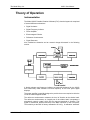
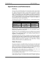
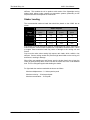
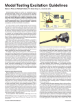
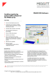
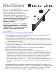
Model 9100C
Portable Vibration
Calibrator
Helping you test, model and modify the behavior of structures.
The Modal Shop, Inc.
9100C User Manual
MODEL 9100C Portable Vibration Calibrator User Manual
3149 East Kemper Road
Cincinnati, OH 45241
Phone: 513.351.9919
FAX: 513.458.2172
www.modalshop.com
Product Support
For answers to questions about the 9100C Portable Vibration Calibrator, consult this manual. For
additional product support, contact The Modal Shop at 800-860-4867 or 513-351-9919, 9 a.m. to 5 p.m.
EST. If it is more convenient, fax questions or comments to The Modal Shop at 513- 458-2172 or email
our sales staff at [email protected].
Warranty
The Modal Shop, Inc. products are warranted against defective materials and workmanship for ONE
YEAR from the date of shipment, unless otherwise specified. Damage to equipment caused by incorrect
power, misapplication, or procedures inconsistent with this manual are not covered by warranty. If there
are any questions concerning the intended application of the product, contact an Applications Engineer.
Batteries and other expendable accessory hardware items are excluded.
Copyright
Copyright © 2009 the Modal Shop, Inc. This manual is copyrighted with all rights reserved. The manual may not be
copied in whole or in part for any use without prior written consent of The Modal Shop, Inc.
Disclaimer
The following paragraph does not apply in any state or country where such statements are not agreeable with local
law:
The Modal Shop, Inc. provides this publication “as is” without warranty of any kind, express or implied, including but
not limited to, the implied warranties of merchantability or fitness for a particular purpose. This document is subject to
change without notice, and should not be construed as a commitment or representation by The Modal Shop, Inc.
This publication may contain inaccuracies or typographical errors. The Modal Shop, Inc. will periodically update the
material for inclusion in new editions. Changes and improvements to the product described in this manual may be
made at any time.
Trademarks
® ICP is a registered trademark of PCB Group, Inc.
MAN-0031 Rev F
July 6, 2009
MAN-0031 rev F
Page 2 of 20
800-860-4867
The Modal Shop, Inc.
9100C User Manual
Table of Contents
INTRODUCTION.............................................................................................................................. 4
Welcome ............................................................................................................................. 4
Customer Support ............................................................................................................... 4
Cautionary Notes ................................................................................................................ 4
Transportation ..................................................................................................................... 5
Shipping .............................................................................................................................. 5
Optional Fixturing and Accessories .................................................................................... 5
THEORY OF OPERATION.............................................................................................................. 6
Instrumentation ................................................................................................................... 6
Battery and Charger............................................................................................................ 7
Warning! .......................................................................................................................7
Special Handling/Storage ............................................................................................. 7
OPERATION.................................................................................................................................... 8
Cautionary Notes ................................................................................................................ 8
Operating Steps .................................................................................................................. 8
Typical Sensor/Fixture Payloads ........................................................................................ 9
Helpful Suggestions ............................................................................................................ 9
Using The Reference Accelerometer................................................................................ 10
SPECIFICATIONS AND PERFORMANCE................................................................................... 11
Accuracy ........................................................................................................................... 11
Shaker Resonance............................................................................................................ 11
Shaker Loading .................................................................................................................12
RECOMMENDED PRACTICES .................................................................................................... 13
Operation Check and Recalibration .................................................................................. 13
Standard Checks For Transducers ................................................................................... 13
Typical Accelerometer Checkout................................................................................ 13
Typical Velocity Sensor Checkout.............................................................................. 14
Cable and Connector Check............................................................................................. 14
Non-Contact Displacement Sensor Calibration ................................................................ 14
Non-Contact Displacement Sensor Test Setup ................................................................ 15
Non-Contact Displacement Sensor Frequency Response Check.................................... 19
Non-Contact Displacement Sensor Linearity Check......................................................... 19
Maintenance...................................................................................................................... 20
Declaration of Conformance ............................................................................................. 20
MAN-0031 rev F
Page 3 of 20
800-860-4867
The Modal Shop, Inc.
9100C User Manual
Introduction
Welcome
Thank you for choosing TMS Model 9100C.
The TMS Model 9100C Portable Vibration Calibrator (PVC) provides a field tested
method for on-the-spot dynamic verification of accuracy. Accelerometers, velocity
pickups and non-contact displacement transducers are accommodated. Optional
fixtures and hardware needed to facilitate mounting most transducers to the
vibrating shaker head are available upon request.
The 9100C incorporates a built-in sine wave oscillator, power amplifier,
electromagnetic shaker, NIST traceable reference accelerometer, digital display,
batteries, and external power supply/charger. The 9100C is a completely self
contained unit that operates on battery or AC power.
The built-in reference accelerometer is attached permanently to the shaker
armature. This maximizes the accuracy between the reference accelerometer and
the test transducer. The 9100C is designed to provide long term reliable
performances over the frequency range of 30 Hz to 10 kHz. The 9100C can be
used for a variety of applications that include:
• Verification and Calibration of vibration transducers and related test systems.
• Verification of connector and cabling integrity.
• Verification of speed indicator measuring systems.
Customer Support
The Modal Shop, Inc. is a PCB Group Company, and we are 100% committed to the
PCB Group’s pledge of ‘Total Customer Satisfaction’. If at any time you have
questions or problems with the 9100C system, please contact an applications
engineer at The Modal Shop by any of the following:
Telephone:
Toll Free:
Fax:
Email:
513-351-9919
800-860-4TMS (4867)
513-458-2172
[email protected]
Cautionary Notes
• Loads of up to 750 grams (26.5 ounces) can be mounted directly to the shaker
head. Larger loads may be applied to the shaker head, however, if prolonged
testing of a heavy load is planned, we recommend using an external transducer
suspension system. Under these conditions the vibration waveform should be
viewed on the oscilloscope to aid in positioning the test transducer and shaker
head to reduce distortion that can occur with very large weights.
• The 9100C should always be operated on a stable flat surface
• The 9100C is designed for field test applications but care must be exercised in
order to maintain the integrity of the shaker head assembly.
MAN-0031 rev F
Page 4 of 20
800-860-4867
The Modal Shop, Inc.
9100C User Manual
Transportation
When transporting the 9100C, care should be taken to ensure that sudden impacts
are minimized. Any motion of the shaker head that might put abnormal vertical
displacement or side loading should be minimized.
Shipping
When transporting the 9100C via commercial carrier, care should be taken to insure
that sudden impacts will be minimized. Any motion of the shaker head that might
exert abnormal vertical displacement or side loading can damage the flexure
system. The original shipping box is packed with sufficient foam to provide a good
cushion for normal transportation environments.
DO NOT USE GROUND TRANSPORT SYSTEMS THAT MACHINE SORT
CARGO. Use FEDX, UPS Next Day or 2nd Day Air. Do not use UPS Ground!
Optional Fixturing and Accessories
For operation in certain applications, such as calibration of non-contact
displacement sensors, TMS offers optional mounting fixturing. Reference the table
below when ordering these optional adapters and accessories.
MAN-0031 rev F
Accessory
Description
S4A-1
Non-contact displacement sensor holder, with micrometer and target.
S4A-2
Steel target, non-contact displacement sensor calibration
S4A-3
Universal transducer adapter, circular plate for custom mounting holes
to be drilled and tapped by user.
S4A-4
Screw adapter kit, includes:
•
Stud adapter, 6-32 internal thread, ¼ external thread
•
Mounting stud, 10-32 to ¼-28 x 0.30” long, BeCu
•
Mounting stud, ¼-28 to ¼-28 x 0.365” long BeCu w/ shoulder
S4A-5
Ruggedized transportation case
S4A-6
Power supply / charger
S4A-7
Replacement battery
Page 5 of 20
800-860-4867
The Modal Shop, Inc.
9100C User Manual
Theory of Operation
Instrumentation
The Model 9100C Portable Vibration Calibrator (PVC) electrical system is comprised
of several different mechanisms.
• Digital Voltmeter
• Digital Frequency Indicator
• Power Amplifier
• Electromagnetic Shaker
• Reference Accelerometer
• Signal Generator
Also included are batteries and an external charger discussed in the following
section.
A digital voltmeter and frequency indicator are especially designed for the 9100C
that continuously reads vibration level and frequency on the front panel digital
displays.
The power amplifier is specially designed to provide the current required to drive the
coil of the electromagnetic shaker
The reference accelerometer measures the level of vibration at the shaker head.
The reference accelerometer, an integral part of the shaker head, incorporates a
piezoelectric ceramic crystal, which has an output proportional to vibration. This
signal is conditioned, buffered and sent to the BNC connector on the front panel.
The sensitivity at the BNC is factory calibrated to 50 mV/g. A calibration “standard”
MAN-0031 rev F
Page 6 of 20
800-860-4867
The Modal Shop, Inc.
9100C User Manual
is maintained by TMS that is used to calibrate the 9100C and maintain NIST
traceability.
The signal generator produces a variable frequency sine wave, which becomes the
source of the driving signal to produce the vibration at the shaker head. The
amplitude of this sine wave signal is controlled by the front panel AMPLITUDE
control. The frequency is also controlled by the front panel FREQUENCY control.
The vibration levels can be read in English or Metric units set by a front panel
switch. Frequency is read in Hz.
Battery and Charger
The Model 9100C can be operated from AC line power or from its internal
rechargeable batteries. When the external power supply is connected, it becomes
the primary power source operating the unit as well as charging the battery.
Battery power is supplied by a sealed solid gel lead acid 12 VDC rechargeable
battery. The battery is designed for continuous charging without damage. Keeping
the battery with full charge means the 9100C will be ready when needed. Under
normal operation the 9100C will operate in excess of 4 hours with a fully charged
battery.
Charge life is directly dependent on the power used. When testing requires high
forces to drive the test transducer, the charge life will be shortened.
Warning!
A COMPLETE DISCHARGE WILL MOST LIKELY CAUSE BATTERY FAILURE.
When the “Bat” battery indication is seen on the display, switch over to AC power. If
the warning is given again TURN THE UNIT OFF!!
Under normal conditions the battery will obtain a full charge with 2-4 hours of charge
time. For every hour of discharge, the unit must charge for 1.5 hours. If deep
discharge occurs, 2 or more days may be required to reach full charge. If the
battery can not reach adequate charge, replacement batteries (S4A-7) are available.
Special Handling/Storage
The internal battery should provide long-term service under normal operating
conditions. The units are securely mounted so that no damage can occur from
shipping or normal transportation. No special handling should be required. TMS
does not recommend that the battery be removed for shipping or storage for periods
less than three (3) months. However, it is recommended that the unit be kept “on
charge” when in storage.
MAN-0031 rev F
Page 7 of 20
800-860-4867
The Modal Shop, Inc.
9100C User Manual
Operation
Cautionary Notes
ALWAYS USE A WRENCH TO HOLD THE SHAKER HEAD WHEN CHANGING
THE TEST SPECIMEN
The end user is encouraged to take every precaution to ensure that the 9100C is
not misused. Overloading the unit for extended periods at high amplitudes is
strongly discouraged. Following these precautions will help prolong the life of the
vibrator sub-assembly.
As long as the displacement limits of the vibrator are not exceeded, the full power of
the amplifier can be used to drive the shaker. If the 9100C is being used to test a
large load, the amplitude limit must not be reached.
When relatively light loads are being tested at lower frequencies, care should be
taken to avoid repetitive contact with the limit stops. Continual hitting of the limits
will result in damage to the moving elements and an increase in distortion.
The care given when mounting a test transducer to the shaker head often has a
direct influence on the accuracy of the calibration. In fact, improper mounting can
lead to erroneous readings and may cause damage to the test transducer and/or the
9100C.
When tightening or removing a test transducer, hold the shaker head with the
wrench to prevent a circumference torque from being applied to the shaker
suspension system. The Model 9100C is more vulnerable to “twisting” damage than
any other abuse. When applying torque, do not exceed twenty inch pounds.
IF THE TONE OF THE UNIT CHANGES WHEN THE AMPLITUDE IS INCREASED,
THE SHAKER IS BEING OVERDRIVEN.
DO NOT DRIVE THE DISPLACEMENT AMPLITUDE SO HIGH THAT THE
ELEMENT “BANGS” THE STOPS.
DON’T FORGET TO TURN THE 9100C OFF. PLUG IN THE CHARGER WHEN
FINISHED.
The batteries are sealed, solid gel, lead acid, and like to be charged when at rest. It
is advisable to keep the unit on charge when not in use.
Operating Steps
The operator can set the 9100C to display data in English or Metric units.
1. Set the Amplitude Function switch according to the type of transducer being
checked.
Sensor Type
9100C Setting
Display Units
Accelerometer
ACC
g peak
Velocity
VEL
ips peak
Displacement
DISP
mils peak to peak
Make sure the Amplitude Adjustment control is turned to a minimum before turning
the power switch on. This is to prevent unnecessary jolting of the shaker head and
the test transducer.
MAN-0031 rev F
Page 8 of 20
800-860-4867
The Modal Shop, Inc.
9100C User Manual
2. Set the Frequency Range switch to the lowest position, 10 Hz to 100 Hz. As a
general rule, it is best to start applying vibration to the test transducer in the 60 Hz to
100 Hz range.
3. Be certain the Internal/External Drive switch is in the Internal position.
4. Turn the Power switch On.
a. If the level is too high, turn the Amplitude dial down.
b. Turn the Frequency Adjust control to read 100 Hz.
c.
Turn the Amplitude Adjust control to set the desired vibration level. (As
indicated on Amplitude display).
5. Verify that the level indicated on the 9100C is the same as the level being read
on the monitor or analyzer that the test transducer is connected to.
6. Always plug the 9100C into AC power when available, always keep on charge
when not being used. The batteries can not be overcharged; however, damage
may occur with too much discharge.
Typical Sensor/Fixture Payloads
Test Transducer and Mounting Fixture Weight Examples:
Sensor Type
Sensor Weight
Required Fixture
Fixture Weight
CEC Instruments 4123-0001 Velocity
121 grams
S4A-3
23.5 grams
Endevco 2217E
32 grams
10-32 adapter
N/A
IMI 602A01
94 grams
Direct
N/A
Wilcoxon 793
110 grams
Direct
N/A
Helpful Suggestions
1. Ensure that the adjoining surfaces of the shaker head and the fixture or test
transducer to be mated are free from dirt, paint, epoxy, scratches, etc.
2. Ensure that all mating threads match and contain no burrs or mechanical
distortion. Clean the threads with a tap (or die) when the threads appear to be
worn.
3. After cleaning the threads coat them with a light oil.
4. Using the correct fixture or threaded adapter, mount the test transducer onto the
shaker head using a light oil on all mating parts and threads especially if testing is to
be performed at frequencies above 500 Hz.
5. For measurements involving frequencies above 1 kHz both surfaces should be
flat and parallel within 1 Mil and have a 32 millionth of an inch surface smoothness.
6. Tightening.
For best results, torque the transducer per manufacturers
specifications when calibrating. Be sure to secure the shaker head with a wrench
while applying torque. Damage to the suspension system can occur when twisting
forces are applied.
MAN-0031 rev F
Page 9 of 20
800-860-4867
The Modal Shop, Inc.
9100C User Manual
7. When fitting test fixtures and test transducers onto the shaker head, aim to keep
the center of gravity directly above and in line with the center axis of the ¼ - 28
threaded hole. This will help avoid side loading the shaker element.
Using The Reference Accelerometer
The internal reference accelerometer signal is available on the front panel ‘Ref Out’
connector. This can be used with volt meters, analyzers, oscilloscopes, and other
measuring devices. The output impedance is 100 ohms and has a sensitivity of 50
mV/g peak. Dial this sensitivity into the instrument or analyzer being checked and
its scale should then agree with the vibration level indicated on the 9100C.
MAN-0031 rev F
Page 10 of 20
800-860-4867
The Modal Shop, Inc.
9100C User Manual
Specifications and Performance
Accuracy
The main section of the Model 9100C is the electrodynamic vibrator, which provides
the vibration required to test transducers. The moving part of the vibrator contains
the reference accelerometer which, combined with its electronics, is factory
calibrated and traceable to the National Institute of Standards and Technology
(NIST). The 9100C performance record indicates that the built-in standard be recalibrated annually depending on the frequency of use and the amount of care given
the unit. A simple calibration check is outlined that can be performed frequently. A
more detailed check can be provided by TMS or through any standards or
instrument lab with vibration testing capabilities.
The Model 9100C provides ± 3% indicated value (IV) ± 1 digit amplitude accuracy
over the following ranges:
Measurement
Amplitude
Frequency Range
Acceleration (G)
0 – peak
35 Hz to 2 kHz
Velocity (IPS)
0 – peak
35 Hz to 400 Hz
peak – peak
35 Hz to 150 Hz
Displacement (Mils)
Accuracy from 30 to 35 Hz is 5%. The ability to provide performance at higher
frequency ranges in velocity and displacement are limited by several factors. The
major factor is the amount of force available from the electromagnetic vibrator.
Distortion may increase to 8% THD at 30 Hz.
Accuracies of ± 10% in the acceleration mode can be obtained over the extended
range of 2 kHz to 10 kHz provided proper care is given when mounting the test
transducer to the shaker head. Refer to the Transducer Mounting section for
suggestions on mounting precautions.
At frequencies below 30 Hz, the force is reduced to the point where the element
cannot keep up with the change in the magnetic field. Severe distortion may result.
Frequencies below 30 Hz are for reference only and carry no accuracy statement.
Distortion specifications are stated only for the 3% accuracy ranges. Distortion
numbers outside this range are to dependant on the mass driven, mounting
techniques, and other factors not controllable by the maker.
Shaker Resonance
The primary resonance in the Model 9100C is the total mass of the shaker head
(including the transducer mounted on the shaker) acting against the spring support
system. This resonance is not apparent in the output of the shaker system and only
affects the amount of drive current required to drive the moving element. This limits
the low frequency operation, but is helped by increasing the mass.
The 9100C has a high weight ratio for an instrument its size due to the
electrodynamics vibrator sub-assembly and the lead acid battery.
The electromagnetic vibrator operates much like a very large loud speaker coil, with
the cone replaced by a flexure system.
A high strength moving coil is accurately located in the annular gap by means of a
flexible suspension systems. This allows vertical motion yet exhibits a high lateral
MAN-0031 rev F
Page 11 of 20
800-860-4867
The Modal Shop, Inc.
9100C User Manual
stiffness. This enables the coil to produce axial motion of the lightweight moving
shaker head, without undue restraint on suspension systems, particularly at low
frequencies where the amplitude is at maximum.
Shaker Loading
The recommended maximum loads that should be placed on the 9100C are as
shown:
Shaker Payload
Frequency
Range
0 – 100
grams
100 – 250
grams
250 – 500
grams
500 – 750
grams
30 – 100 Hz
10 g
4g
2g
1g
100 – 1 kHz
7g
4g
2g
1g
1 – 2 kHz
3g
1.5 g
1g
N/A
2 – 10 kHz
3g
1.5 g
N/A
N/A
If the 9100C is used to test heavier loads for extended periods of time, some form of
external support, such as elastic suspensions or slip tables, should be used. Failure
to support these excessive loads may result in damage to the moving coil and
flexure.
Care must be taken when testing high aspect ratio loads, which exhibit a low
stiffness. Severe rocking modes can produce high lateral loads on the moving coil
and flexure, resulting in damage.
When fitting test transducers and fixtures onto the shaker head, aim to keep the
center of gravity directly above, and in line with the center axis of the ¼-28 threaded
hole. This is a safeguard against side loading the shaker.
For light loads the maximum attainable levels are as follows:
Maximum displacement – 0.1 inches peak to peak
Maximum velocity – 10 ins/second peak
Maximum acceleration – 10 G’s peak
MAN-0031 rev F
Page 12 of 20
800-860-4867
The Modal Shop, Inc.
9100C User Manual
Recommended Practices
Operation Check and Recalibration
As with all calibration systems, periodic verification of the system’s performance is
strongly recommended. This is best done using a dedicated accelerometer by
calibrating the accelerometer (often call a “verification sensor”) each day that the
unit will be used. Results of the verification should be compared to previous results.
If the calibration of the verification sensor changes, the unit should be evaluated
further to determine the cause of the discrepancy.
The 9100C can be also calibrated in a similar manner using any calibrated
accelerometer by using the accelerometer as the known reference and comparing
its output to the output of the 9100C. Field repair of the 9100C is not possible, so if
the 9100C is out of specification, it should be sent back to The Modal Shop for
evaluation/repair.
For both the operation check and recalibration, a precision accelerometer with a
quartz sensing element is recommended, for example the 9105C transfer standard
available from TMS.
Standard Checks For Transducers
Linearity and frequency response checks should be performed periodically.
Linearity is a check to determine if the output sensitivity (mV/Unit of vibration, i.e.,
mV/g), remains constant from a minimum operating level to higher operating levels.
This check is usually made at 100 Hz. The transducer manufacturer usually
specifies this frequency on the transducer’s original calibration certificate. If in
doubt, use 100 Hz.
Frequency Response is a check to determine that the output sensitivity (mV/Unit of
vibration), or actual reading, is maintained over a normal operating frequency range.
The reference input vibration level is held at a constant level for the frequency
response test.
The following typical transducer checkout tables outline typical test frequencies and
vibration levels for checking accelerometers and velocity transducers. These should
meet most general purpose requirements for verifying the functionality of
transducers and measuring systems.
Follow the operating procedure in the Operating Steps section.
frequencies and levels given in the tables.
Substitute the
Be certain to turn down the Amplitude control before switching the Frequency
Range switch to avoid jolting the shaker.
Typical Accelerometer Checkout
Linearity Check (Frequency = 100 Hz)
Reference Level
0.25 g
0.5 g
1.0 g
2.0 g
3.0 g
Actual Level
MAN-0031 rev F
Page 13 of 20
800-860-4867
The Modal Shop, Inc.
9100C User Manual
Frequency Response Check (Level = 1 g)
Reference Level
100
200
500
1000
4000
0.6
0.8
1.0
100
200
400
Actual Level
Typical Velocity Sensor Checkout
Linearity Check (Frequency = 100 Hz)
Reference Level (ips)
0.2
0.4
Actual Level
Frequency Response Check (Level = 0.2 ips)
Reference Level
30
70
Actual Level
Cable and Connector Check
Following the performance checks for transducers and their measurement systems,
one should check for cable and connector integrity. Run the 9100C at a high
frequency and at a moderate-to-high vibration level. Check for possible signal
interruptions that would occur if looseness was present. Looseness may not be
detected at low frequencies, but can become very detectable at higher frequencies.
Non-Contact Displacement Sensor Calibration
Non-contact displacement sensors, also referred to as proximity probes, eddy
current probes or simply displacement probes, can be checked for accuracy,
linearity, and frequency response. Proximity probe systems require the use of the
optional S4A-1 proximity probe mounting attachment, shown on the next page. The
following sections detail the procedure for performing linearity and frequency
response checks on a non-contact displacement sensor.
MAN-0031 rev F
Page 14 of 20
800-860-4867
The Modal Shop, Inc.
9100C User Manual
Non-Contact Displacement Sensor Test Setup
Note: The calculations in these instructions are based on a 200 mV/mil eddy
current proximity probe to provide an example based on nominal sensitivity. In
some cases the proper proximity probe, extension cable, and proximitor must be
matched in order to obtain the expected output from this type of transducer.
1. If this is the first use after receiving the S4A-1 you must release the microarm
shown below by breaking the set screw loose so the microarm can move relative to
the micrometer’s barrel.
Microarm
MAN-0031 rev F
Set Screw
Page 15 of 20
800-860-4867
The Modal Shop, Inc.
9100C User Manual
2. Remove the (2) 10-32 pan head screws on the user panel of the portable
vibration calibrator (white arrows in picture below).
3. Install the steel target into the shaker on the shaker head.
MAN-0031 rev F
Page 16 of 20
800-860-4867
The Modal Shop, Inc.
9100C User Manual
4. Install the non-contact displacement sensor in the microarm after stringing the
probe thru the probe bar as shown in the picture below. Please note: An 8mm noncontact displacement sensor with 3/8 - 24 threaded case will mount directly while a
5mm non-contact displacement sensor with a ¼ - 28 threaded case requires the
supplied bushing. Slide the non-contact displacement sensor into the microarm;
tighten the socket head cap screw inside the microarm to lightly squeeze the probe
to ensure the probe is held securely.
Socket Head
Cap Screw
Set Screw
5.
Disassemble as required and carefully layout the assembly to resolve the
required spacer or spacers to hold the non-contact displacement sensor the proper
distance for the target as shown below. The non-contact displacement sensor will
need to be held so that the sensor will contact the target and must be capable of
traveling 200 mils before the micrometer runs out of travel.
Non-contact
displacement sensors come in various lengths so adjustability has been designed
into the assembly. Attach selected spacer or spacers using setscrews provided,
leaving threaded holes exposed.
MAN-0031 rev F
Page 17 of 20
800-860-4867
The Modal Shop, Inc.
9100C User Manual
6.
Finalize the assembly by attaching probe bar, microarm, non-contact
displacement sensor, and micrometer on top of the spacers and secure with
provided panel screws.
MAN-0031 rev F
Page 18 of 20
800-860-4867
The Modal Shop, Inc.
9100C User Manual
Non-Contact Displacement Sensor Frequency
Response Check
1. Set the micrometer to 0 mils, release the microarm with the set screw and slide
the microarm down the barrel of the micrometer. Tighten the set screw to hold the
microarm and probe when the probe makes contact with the target.
Note: A piece of paper or metal shim can be used to improve accuracy of zero
position. If utilizing this method set micrometer to thickness of paper or shim and
lower microarm and non-contact displacement sensor onto the shim until friction is
felt between the shim and the target and probe then secure with the set screw.
2. With the non-contact displacement sensor powered up and the output wired to a
voltmeter set to DC voltage, adjust the micrometer so the gap between the probe tip
and the steel target is around 50 Mils. If you are using a 200 mV/mil proximity probe
the voltmeter should read between -8 and -11 volts DC. Fifty mils is the typical
recommended gap setting for non-contact displacement sensors, and will ensure
that you are in the sensors linear output range. Consult your non-contact
displacement sensor’s user manual for additional information.
3. IMPORTANT: Set the Amplitude Function switch to Displacement and turn the
AMPLITUDE adjustment to the minimum level BEFORE powering the 9100C to
avoid damaging the non-contact displacement sensor.
4. Set the Frequency Range switch to 10 to 100 Hz position.
5. Be certain the External/Internal Drive switch is locked in the Internal position.
Turn the Power switch on and set the test frequency to 100 Hz using the Frequency
Adjust control.
6. Increase the vibration level to 5 mils pk to pk using the Amplitude Adjust control.
Check the non-contact displacement sensor system output using an AC voltmeter or
a vibration monitoring system indicator for the correct level ± 5%. If the
displacement system output sensitivity is 200 mV/mil, the AC voltmeter should read
approximately 353.5 mV rms (70.7mV x 5mils). An oscilloscope should read
approximately 1 V pk to pk (200 mV x 5mils).
7. Make corresponding measurement checks at other frequencies in the 30 Hz to
100 Hz range, then turn the vibration level to minimum. Set the Frequency Range
switch to 100 to 1000 Hz and turn the Frequency Adjust control to minimum.
8. Turn the Power On and set the vibration level to 5 Mils again and continue
making corresponding measurement checks in the 100 Hz to 150 Hz range.
9. Turn the vibration level to minimum, and turn the Power Off when calibration
checks are complete. Remove the displacement sensor and then store the
proximity probe fixture and the target.
Non-Contact Displacement Sensor Linearity Check
Note: Reference steps 1-6 of “Non-Contact Displacement Sensor Test Setup”
section earlier in this manual for setup instructions.
1. Power up the probe driver and connect a digital voltmeter to the output.
2. Set the micrometer to the number of mils corresponding to the center of the linear
range for the probe being tested.
MAN-0031 rev F
Page 19 of 20
800-860-4867
The Modal Shop, Inc.
9100C User Manual
3. Loosen the set screw holding the probe in the adapter.
4. Move the probe toward the target until the DC voltage, measured at the driver
output, corresponds to the recommended gap voltage for the transducer under test
(7.5 to 12 VDC typical).
5. Retighten the set screw.
6. Adjust the micrometer to the specified minimum gap reading and record the
voltage on the voltmeter. Do not let the probe touch the target.
7. Increase the gap with the micrometer in either five or ten mil steps and record the
voltage at each step.
8. Divide the voltage output at each step by the number of mils per step. This value
when converted to millivolts DC corresponds to the transducer sensitivity, typically
200 mV/mil.
9. Upon completion of tests, remove and store the probe adapter and the target.
OPTIONAL METHOD:
Perform the linearity check above except operate the 9100C at 100 Hz with very low
displacement level. This is to create a very low “delta gap” condition for the
measurements. The low delta gap sometimes results in a smoother calibration
curve.
Maintenance
Recalibration and certification is recommended on an annual basis. Service of
internal parts should only be performed by factory personnel. If the unit is removed
from the case, the NIST calibration is void. Recertification can only performed after
re-assembly.
Declaration of Conformance
The Modal Shop, Inc. declares that
MAN-0031 rev F
•
Model 9100C Portable Vibration Calibrator is in accordance with the
following directives:
•
89/336/EEC The Electromagnetic Compatibility Directive and its amending
directives has been designed and manufactured to the following
specifications:
•
Generic Emissions Standard (EN 50081-1: 1992 Part 1: Residential,
commercial and light industry)
•
Generic Immunity Standard (EN 50082-1: 1977 Part 1: Residential,
commercial and light industry and EN 50082-2: 1995 Part 2: Industrial
environment).
Page 20 of 20
800-860-4867