1
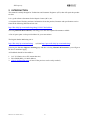
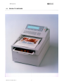
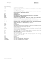
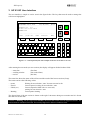
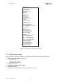
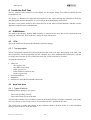
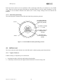
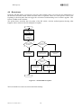
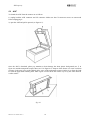
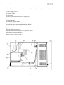
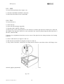
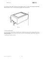
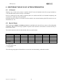
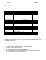
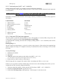
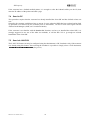
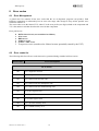
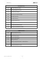
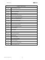
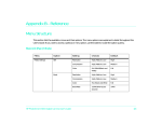
H
HP Property
HP 9100C Digital Sender
Service Manual
Rev.C
HP P/N C1311-90009 - Rev. C
H
HP Property
TABLE OF CONTENT
1
REVISION HISTORY .................................................................................................................................... 4
2
INTRODUCTION ........................................................................................................................................... 6
PRODUCT OVERVIEW ....................................................................................................................................... 7
2.2 REPAIR OVERVIEW ................................................................................................................................ 10
2.3 GLOSSARY .................................................................................................................................................. 11
3
HP 9100C USER INTERFACE..................................................................................................................... 12
3.1 ENTERING THE TEST MODE (SHIFT + ALT + D) ................................................................................. 13
3.2 HARDWARE PARTS TESTED ........................................................................................................................... 14
3.3 HARDWARE TEST LIST ................................................................................................................................. 15
3.4 CONTROL PANEL.................................................................................................................................... 15
3.4.1
Control Panel Self Test Hardware Requirements ................................................................................ 16
3.4.2
CP Self Test description ..................................................................................................................... 16
3.5 SPECIAL KEY LIST.................................................................................................................................. 17
4
INSIDE THE SELF TEST ............................................................................................................................ 18
4.1 DIMM MODULE .......................................................................................................................................... 18
4.2 PCA............................................................................................................................................................ 18
4.2.1
Test description ................................................................................................................................. 18
4.3 HARD DISK DRIVE ........................................................................................................................................ 18
4.3.1
Types of failures ................................................................................................................................ 18
4.3.2
Hard disk partitioning........................................................................................................................ 19
4.4 JETDIRECT CARD ......................................................................................................................................... 19
4.4.1
Types of failures ................................................................................................................................ 19
4.4.2
JetDirect self-test............................................................................................................................... 20
4.5 SCANNER ENGINE AND ADF......................................................................................................................... 20
4.5.1
Scanner engine test ............................................................................................................................ 20
4.5.2
ADF test ............................................................................................................................................ 20
4.6 BOOT PHASE ................................................................................................................................................ 22
5
HARDWARE INTERVENTION.................................................................................................................. 23
5.1 SHUTDOWN FIRST!................................................................................................................................. 23
5.2 CONTROL PANEL.................................................................................................................................... 24
5.3 ADF ........................................................................................................................................................... 25
5.4 JETDIRECT LAN CARD ................................................................................................................................ 26
5.5 ACCESSING INTEGRATED SCANNER INTERNAL PARTS ................................................................................... 27
5.5.1
HDD.................................................................................................................................................. 29
5.5.2
PCA................................................................................................................................................... 29
5.6 ACCESSING ADF INTERNAL PARTS .............................................................................................................. 31
6
RESTORING THE HP 9100C AFTER INTERVENTION.......................................................................... 32
6.1 IN GENERAL ................................................................................................................................................ 32
6.2 SPECIAL CASES............................................................................................................................................ 32
6.2.1
If the HDD has been replaced ............................................................................................................ 33
6.2.2
If the JetDirect Card has been replaced.............................................................................................. 33
6.2.3
Conformity test (SHIFT + ALT + DUPLEX)....................................................................................... 34
6.2.4
If the main PCA has been replaced..................................................................................................... 34
7
DEMONSTRATION ..................................................................................................................................... 35
7.1
7.2
7.3
7.4
7.5
8
CHECK JOBS ................................................................................................................................................ 35
SEND VIA E-MAIL ........................................................................................................................................ 35
SEND VIA JETSEND ...................................................................................................................................... 35
SEND TO PC ................................................................................................................................................ 36
SEND VIA LAN FAX ................................................................................................................................... 36
ERROR CODES............................................................................................................................................ 37
8.1
ERROR MANAGEMENT ................................................................................................................................. 37
HP P/N C1311-90009 - Rev. C
2
H
HP Property
8.2
ERROR CODES LIST....................................................................................................................................... 37
HP P/N C1311-90009 - Rev. C
3
H
HP Property
1 REVISION HISTORY
DATE
REVISION
DESCRIPTION
PAGE(s)
CHANGED
15-Oct-1998
31-Mar-1999
B
C
Section 2.1 has changed
Revision History added (page numbering has changed)
13
4
HP P/N C1311-90009 - Rev. C
4
H
HP Property
HP P/N C1311-90009 - Rev. C
5
H
HP Property
2 INTRODUCTION
This manual is mainly thought for Technicians and Customer Engineers (CE's) that will repair the product
On Site.
It is a good reference document for the Repair Centers (RC's) too.
A Computer Based Training and more information about the product, literature and specifications can be
found at the following HP internal web site:
http://bhc.italy.hp.com/marketing/mktg1/9100C/default.htm
Selecting Manuals & Documents, will bring you to the most updated documents available.
A list of spares parts is also provided there for your convenience.
The Digital Sender Marketing site is:
http://bhc.italy.hp.com/marketing
(old site http://quovadis.italy.hp.com/marketing)
[Entering the Service~Support~Training page and then selecting Manuals & Documents, you will get to
the above mentioned page.]
All feedback should be forwarded to:
1- CCC (US Boise site or EU Amsterdam site)
2- ESCAMGR,BHC (CC:Mail address)
3- [email protected] (if none of the previous can be easily reached)
HP P/N C1311-90009 - Rev. C
6
H
HP Property
2.1 PRODUCT OVERVIEW
HP P/N C1311-90009 - Rev. C
7
H
HP Property
HP P/N C1311-90009 - Rev. C
8
H
HP Property
______________________________________________________________________________
FRONT VIEW
• Integrated Scanner (IS or NB)
‚ Automatic Document Feeder (ADF)
ƒ Control Panel (CP)
_______________________________________________________________________________
REAR VIEW
• ADF connector
‚ CP connector
ƒ External power inlet
„ Network Card (NC)
… Continuos Scanning Switch hole
(Used only under CCC directions, not documented)
† Fan grid
HP P/N C1311-90009 - Rev. C
9
H
HP Property
2.2 REPAIR OVERVIEW
Here are described the logical steps to repair the HP 9100C, and the related chapters.
2
SELF TEST
(troubleshoot)
4
HW INTERVENTION
2
3
SELF TEST
(verify)
5
RESTORE
6
DEMO
HP P/N C1311-90009 - Rev. C
10
H
HP Property
2.3 Glossary
ADF
API
BHC
CCC
CP
DC
DOA
DOS
DSTS
EST
F1… F4
FW
HDD
ISV
LAN
LPCD
NB
PC
PCA
SFC
S/N
SW
UUT
VERONA
VOLTERRA
HP P/N C1311-90009 - Rev. C
Automatic Document Feeder
Library of functions that allows to interface to lower hardware devices without
knowing their details.
Bergamo Hard Copy Division.
Customer Care Center. These are the Support Centers customers will call for
help about Software and Hardware problems.
Control Panel.
Distribution center.
Dead On Arrival: unit that doesn’t function when arrives to the customer.
Microsoft MS-DOS operating system.
Windows 32 bit application that manages test sessions for The HP 9100C,
interfacing to it trough serial communication. Used in MFG only
Extended Self Test utility integrated in The HP 9100C that allows to run
diagnostics using the Control Panel's LCD and keyboard as user interface.
The four soft keys under the LCD display. They execute several commands
depending upon the selected feature of the HP 9100C. The LCD indicates their
function. When there is no indication the key is not active.
Firmware
Hard Disk Drive
Indipendent Software Vendor, it could refer to applications not bundled with the
product that can receive files from the HP 9100C
Local Area Network
LaserJet Products Completion and Distribution. United States site where The HP
9100C is integrated and distributed.
Network Box. This is the Scanner Engine with all the electronics (PCA, LAN
Card, HDD…) and it is the bottom module of the unit.
Personal Computer
Printed Circuit Assembly.
Shop Floor Controller: software that manages integration flow and logs
integration, test and defect data.
Serial Number
Software
Unit Under Test.
Code name for the HP 9100C Digital Sender
Code name for the HP Network ScanJet 5.
11
H
HP Property
3 HP 9100C User Interface
The user interface is simple as can be seen in the figure below. The keys that must be used to manage the
self-test are highlighted.
EXTENDED SELF TEST
Failed(103) 00:15
----------------------------------------PCATST rev. 1.0
Flash revision check
ERROR 103
<I>
//
----------------------------------------*PCA
JetDirect *ADF *Scanner
HDD
?
Q
W
A
E
S
R
D
T/t
Z
X
shift
Alt
space
T
F
C
Y
G
V
U
H
I
J
B
N
.
@
O
K
M
P
-
L
return
shift
1
2
3
4
5
6
7
8
9
*
0
#
Figure 3-1 Control panel layout with example of self test screen after a test run.
After entering the test mode (see next section), the display will appear divided in three fields:
− status line
− scrolling window
− test list
(first line)
(four central lines)
(last line)
The status line shows the status of the self-test and the result of the last test session (if any).
The status can have the following values:
− (none)
− Passed
− Failed (xxx)
− Running
Waiting for test selection / start. No tests executed so far.
Last test passed; waiting for test selection / start.
Last test sequence failed with xxx error code;
waiting for test selection / start.
Test sequence running.
The elapsed time of the test session is shown on the right. It increases during test execution and it is frozen
after the test session ends.
If status is “Running” but the elapsed time STOPS, this means that a fatal error has happened and the test
session must be considered FAILED. This usually happens for defective JetDirect cards.
HP P/N C1311-90009 - Rev. C
12
H
HP Property
The four central lines are used as a scrolling window to display information (revision numbers, errors, etc)
and to inform the user on the current state of test execution.
When the test session finishes, using the arrow keys on the right of the LCD it is possible to scroll this
window up and down.
Last line contains the list of available tests. The selected ones have an asterisk (*) on the left.
3.1 ENTERING THE TEST MODE (SHIFT + ALT + D)
The Extended Self Test (EST) built in the product is able to detect with high level of confidence which
hardware part is failing, providing a quick tool to troubleshoot.
Follow these steps to ENTER TEST MODE:
1. Connect Control Panel and ADF, connect power cord, unlock the scanner, power on the unit.
2. Wait until the control panel LCD is completely darkened.
3. As soon as the LCD starts clearing (curtains open), press simultaneously the keys
SHIFT + ALT + D
and release them only when the curtains are completely opened.
4. After approximately 30 second the LCD will display the EST window with keys usage directions.
Press any key to continue. At this point the self test revision is displayed.
5. Select tests to be executed.
To select/deselect a test, press its number using the numeric keypad (1 to 5).
6. If the ADF test is selected, load at least 7 paper sheets in the ADF.
If the Scanner test is selected and the ADF test IS NOT selected, DO NOT load any pages in the ADF.
(The Scanner test will fail if the ADF has still pages on it. If the ADF test has been selected also, it will be executed first, and it will scan all
pages in the ADF, so that when the Scanner test starts the ADF will be empty. If the ADF test IS NOT selected, you have to clear the ADF by
yourself to avoid Scanner test failure)
7. Start the test session pressing the green key.
The execution order is from left to right. It has been set in this way to reduce waiting time in case of failure
and to guarantee to correct sequence when testing both ADF and scanner.
In case of failure the test STOPS, the error code is displayed and on the last line a question is
displayed: “Running test failed. Continue? (y/n)”
It is possible to continue the test session answering ‘y’ or to stop it pressing ‘n’. The session will be
considered failed anyway.
After a completed test session (passed or failed), it is possible to change the test selections and to restart the
testing with the green key.
The following picture shows an example of the log displayed in the scrolling window after a full test session.
Most useful information:
•
•
•
•
•
Each diagnostic shows its revision at the beginning of execution.
Firmware revisions for PCA, scanner and hard disk are shown in the related tests.
Hard disk model is shown.
Partition table is listed. For each partition, displayed information are: type, starting sector, number of
sectors.
For ADF, scanner and hard disk tests, the longer ones, some progress information are displayed.
HP P/N C1311-90009 - Rev. C
13
H
HP Property
PCATST rev. 1.00
Bootblock fw rev. 1.0
Multiplexer fw rev. 0.6
Styx registers test
Giulietta registers test
Memory test
Dimm test
PCA test passed
JDTEST rev. 1.0
Configuring card…
Running BIST…
Waiting for CardReady…
Card ready
JetDirect test passed
SCNTST rev. 1.1
ADF status string: PP
Test n.1: 300 dpi, 24 bpp
Test n.2: 300 dpi, 1 bpp
Average feeding time (ms): 4160
ADF test passed
SCNTST rev. 1.1
Scanner FW: 3828
Test n.1: 600 dpi, 24 bpp
Test n.2: 300 dpi, 1 bpp
Scanner test passed
HDDTST rev. 1.2
QUANTUM FIREBALL SE2.1A
Part. 1: 6 63 [818433]
Part. 1: 6 818497 [2987711]
Part. 1: 6 3806208 [201600]
Part. 1: 131 4011840 [100800]
Firmware revision: 01.00.a
Scanning raw partition…
Scanning DOS partition 1…
Scanning DOS partition 2…
Scanning DOS partition 3…
Hard disk test passed
Figure 3-2 Example of Extended Self Test log
3.2 Hardware parts tested
The test affects all the top-level hardware components of the HP 9100C Digital Sender. They are:
•
•
•
•
Integrated scanner (NB), composed by:
− Scanner Engine
− HP 9100C PCA (PCA)
− Hard Disk Drive (HDD)
JetDirect LAN card
Automatic Document Feeder (ADF)
Control Panel (CP)
(not part of the whole unit EST, must be launched separately, see par. 2.4)
HP P/N C1311-90009 - Rev. C
14
H
HP Property
3.3 Hardware Test List
The following table contains the list of tests available with indication of the key that must be pressed to
enable/disable them, a brief description and the duration.
Test
Key
PCA
1
Description
Duration
Display FW revisions (Boot code and multiplexer code).
10”
Execute all tests listed in the paragraph 4.1.1
JetDirect
2
JetDirect self-test (refer to 4.3.1).
10”
NOTE: this test can be executed only once after each power cycle,
otherwise a timeout error will occur.
ADF
3
Check internal ADF status.
50”
Check lid sensor.
Check paper sensor.
Scan 2 pages at 300 dpi 24 bpp filter on.
Scan remaining pages (at least 5) at 300 dpi 1 bpp, calculating
average feeding time.
Scanner
4
Check internal scanner status.
40”
Display scanner firmware revision.
Scan 1 page at 600 dpi, 24 bpp.
Scan 1 page at 300 dpi, 1 bpp.
HDD
5
Display hard disk model.
Approx.
4’
Display partition table.
Display FW revision.
Read sequentially raw partition (firmware area).
Read sequentially 1. DOS partition.
Read sequentially 2. DOS partition.
Read sequentially 3. DOS partition.
Table 3-1 Description of the tests available in the Extended Self Test.
3.4 CONTROL PANEL
The CP is not tested while running the EST. It has its own built-in self test. If an hardware loopback
connector is used, the data interface can also be tested.
HP P/N C1311-90009 - Rev. C
15
H
HP Property
3.4.1 Control Panel Self Test Hardware Requirements
The CP cable must be plugged into the connector of the network box and the HP 9100C must be ready (boot
phase completed).
[The CP could be connected also to some external source of power, such as a lab power supply. In this case, to execute the self test
the unit needs only to be powered on (VCC +5V, GND 5V, VCC +24V, GND 24V) and its reset line should be pulled up to +5V. If
the data lines and the interface need to be tested, a loop-back connector must be added between the scanner box and the control panel
connector. The purpose of this connector is to connect the CPRDY line to the CPCLK line and the CP2AS line to the AS2CP line
coming from the control panel, leaving only the power lines going from the scanner box to the control panel, in a way to provide the
needed power source. The reset line should be pulled up. This process is not documented for the time being.]
3.4.2 CP Self Test description
1234-
Make sure the HP 9100C is running (boot phase completed)
Disconnect the CP cable from the rear of the HP 9100C
Re-connect the CP cable to power on again the CP
After the screen has become all black and the curtains open, press the keys ALT + SHIFT + 3 and keep
them pressed until the curtains are completely opened. Then release the keys.
The screen becomes again completely black for 4 seconds and the leds will flash. In this phase the user can
check the LCD pixels deterioration or white spots.
Then the screen opens again and the following message is displayed:
"|~~~~~~~~~~|
"| LCD area |
"|__________|
" o o o o
"ooooooooooo
" oooooooooo
"oooooooooo
"oo o oooooo
o o | VER SELF TEST REV.094"
o o | LCD RAM :XX
"
o o | KEYBOARD:XX
"
| PWM=0xXX
"
ooo | TIME=XX:XX:XX RAM0=XX"
ooo | DATE=XX/XX/XX RAM1=XX"
ooo |
"
ooo |
"
Where:
LCD RAM =
KEYBOARD =
PWM =
TIME =
DATE =
RAM0 and RAM1 =
OK or FAIL accordingly to the test results
OK or FAIL accordingly to the test results
from 0x00 to 0xFF, it is the contrast voltage setting
is the time took from the real time clock in the format HH:MM:SS
is the data took from the real time clock in the format YY:MM:DD
are the first two RAM locations in the real time clock.
RAM0=80 means the battery of the clock is low and the clock stopped.
[If a loop-back connector is provided between the CPCLK line and the CPRDY, and between CP2AS and AS2CP, also the data
interface will be tested.
The test will send out data and check what has just received. If the clock line is properly connected, the LCD zone drawn in the
upper left part of the screen will start getting black and then again white, cycling from top to bottom.
If some errors are detected in the receiving line AS2CP, the display will signal it changing some pixels in the LCD area.]
Below the LCD area there are some ‘o’. They represent the keys of the CP.
If a key is pressed, the corresponding ‘o’ in the LCD will be changed to ‘x’ permanently.
HP P/N C1311-90009 - Rev. C
16
H
HP Property
The user should press all the keys one at a time and change all the ‘o’ to ‘x’.
Only the ‘shift’ key will return from ‘x’ to ‘o’ when released, because there are two shift keys to be tested.
The contrast level of the LCD and accordingly the PWM value can be changed by pressing the keys:
[ALT + 5] or [ALT + 6] on the right side of the LCD.
The backlit module can be switched on and off by pressing ALT + GO (green button) or ALT + ABORT
(red button).
3.5 SPECIAL KEY LIST
This table describes all the special key sequences and when they are available.
Key Sequence
Description
Availability
SHIFT ALT ?
Demo Mode
Blue Curtains1
ALT R
Hard Disk Recovery
Blue Curtains
SHIFT ALT F
Restore flash default parameters
Blue Curtains
SHIFT ALT F1
Toggle Boot FW Image
Blue Curtains
SHIFT ALT D
HW Diagnostics
Blue Curtains
SHIFT ALT Go
Configuration Menu
Main Window2 or Login
SHIFT ALT Duplex
Self Test Page
Main Window or Login
SHIFT ALT N
Number of Scanned Pages
Test Page
SHIFT ALT T
Clear Address Book
Fatal Error State3
SHIFT ALT 5
LCD Contrast Darker
Any Time
SHIFT ALT 6
LCD Contrast Brighter
Any Time
SHIFT ALT F4
Task Status
Any Time
SHIFT ALT F3
Dito Control4
Any Time
SHIFT ALT W
Reset To Default
Fatal Error
SHIFT ALT Abort
Force Shutdown
Any Time
ALT F4
Events Sequencer
Any Time
ALT F3
Job Status
Any Time5
ALT 1
Trace Enabled
Blue Curtains6
SHIFT ALT 3
CP Self Test
Any Time7
1
At the very beginning of the boot phase, before two blue “curtains” are opening.
The control panel displays the home screen and the Go button is not blinking.
3
The control panel displays a fatal error.
4
"Dito" is a non documented SW application embedded in the HP 9100C CD ROM - used by CCC.
5
It is equivalent to press the ? button.
6
ALT 2 and ALT 3 are allowed for further tracing.
7
CP must be first turned Off / On by disconnecting / reconnecting the CP cable
2
HP P/N C1311-90009 - Rev. C
17
H
HP Property
4 Inside the Self Test
The two software tools referred to in this chapter are the Digital Sender Test Software (DSTS) and the
Extended Self Test.
The former is a Windows NT application that interfaces to the scanner through the synchronous serial port
and that uploads and runs diagnostics. It is used only in the manufacturing environment
The latter is a test kernel internal to the scanner that can be run without external hardware and that executes
diagnostic programs stored in the hard disk.
4.1 DIMM Module
The Dual In line Memory Module (8MB currently) is mounted on the PCA and its test is performed when
testing the whole board. Refer to the PCA testing for more information.
4.2
PCA
This is the main board located in the NB nearby the Power Supply.
4.2.1 Test description
The PCA diagnostic software (PCATST) includes tests that check some basic functionality of the ASICs and
their connections. All life components (µP NEC VR4300, Styx, Juliet, SDRAM and Flash memory) will not
be deeply tested, because in case of defect the whole test session could not be executed.
The implemented tests are:
• ASICs test
− Styx registers test
− Styx DMA transactions
− Juliet registers test
− Juliet mailboxes read/write test
− Romeo registers test
• On board RAM test
• DIMM test
• Pipeline test (Juliet-Romeo-DRAM connection)
4.3 Hard disk drive
4.3.1 Types of failures
Hard disk failures belong to two classes:
-
Drives not operating correctly
Drives that cannot access all the data.
The first kind of failure is more evident, because the disk simply doesn’t respond to commands, is not ready,
can’t reset and so on. Just trying to access it is possible to detect a problem in this class.
The second class is subtler and contains all the problems related to the disk surface or to the mechanical
ability to reach each area of the disk itself.
HP P/N C1311-90009 - Rev. C
18
H
HP Property
Disks are however able to recover problems of the second type when they are restricted to very limited
areas. There are in fact some spare tracks that are used when defective ones are found. Sometimes it is also
possible to recover failures related to the surface (ECC errors) simply writing on the area that has the
problem.
4.3.2 Hard disk partitioning
The following figure schematizes the HP 9100C hard disk partitioning structure.
FAT partition (DOS like)
for configuration files and
address book (400 MB)
Track 0
FAT partition for images
( > 1.5 GB)
FAT partition, backup for
configuration files
(100 MB)
Raw partition with
product and test firmware
(50 MB)
Track N
Figure 4-1 The HP 9100C hard disk partitioning structure
4.4 JetDirect card
This is the card removable from the rear of the HP 9100C, without opening up the Network Box.
4.4.1 Types of failures
JetDirect testing is composed by two main blocks:
1- Functional test that verifies the card hardware functionality
2- Conformity test that ensures the right model and firmware revision is being used.
HP P/N C1311-90009 - Rev. C
19
H
HP Property
4.4.2 JetDirect self-test
The functional test is performed using the JetDirect self-test (BIST+extended self-test; refer to EIO
specification). It can be executed just once after power-on and stores results in the Status Register and Error
Register of the EIO memory space.
To run the test, a handshaking session must be performed acting on some registers in the network card. A
timeout can be managed to detect “dead” cards that don’t respond.
Duration is approximately 7 seconds.
Main tests run by self-test are:
•
•
•
•
•
•
•
•
Midplane controller register test
DRAM test
EPROM CRC test
Memory-to-memory copy/checksum test
PROM checksum test
FLASH station address test and, for Ethernet models
Frontplane registers test
Ethernet controller tests.
Only fatal errors are notified from JetDirect to peripheral (PCA), thus to the display on the CP.
4.5 Scanner engine and ADF
4.5.1 Scanner engine test
It verifies the ability of the engine to receive commands and checks some functionality related to electronics
and mechanics. No optics tests are performed at all in this phase.
The scanner diagnostic verifies:
•
•
•
•
•
•
Internal self-test status.
Interface to PCA.
Ability to reset and to get to home position.
Lamp functionality (On/Off).
Ability to execute commands and to reply to inquiries (SCL).
Image acquisitions with different settings.
4.5.2 ADF test
The ADF test checks the following ADF functionality:
•
•
•
•
•
Internal ADF status.
Cover lid sensor (must be closed).
Paper presence sensor.
Ability to feed with different settings.
Loading speed with the fastest scanning mode (15 pages/minute).
The sequence of tests is as follows:
HP P/N C1311-90009 - Rev. C
20
H
HP Property
1. Feeding of 2 sheets with this setting: 300 dpi, 24 bpp, enhancement filter on.
2. Feeding of the remaining sheets (at least 5) with this setting: 300 dpi, 1 bpp.
HP P/N C1311-90009 - Rev. C
21
H
HP Property
4.6 Boot phase
Each time The HP 9100C is powered on, the boot code performs some very brief tests, the initialization of
the hardware and then checks which execution mode is requested. There are some specific events at the
beginning of the boot phase that can trigger the execution of manufacturing test or software upgrade. This
feature is hidden to the customer.
The picture below describes the boot phase of the HP 9100C, with the outlined pattern showing what
happens with no actions at the CP during the boot phase.
Start
Perform minimum
selftest
(NEC, memory...)
Configure all the HW
needed to support
multiboot
(sync serial port, HDD)
No
No
Flash upgrade
requested ?
Mfg hook on sync.
serial port ?
Yes
Yes
Load Verona Application
Kernel from HDD
and run it
Load FTMS in memory
from flash and run it
Execute flash upgrade
and restart
Yes
No
Control panel
present ?
Run FTMS in Built-in
Self-test mode
Run FTMS in Integration
Test mode
Stop
Figure 4-2 The HP 9100C boot phase
The boot and the test codes are stored in the flash memory .
HP P/N C1311-90009 - Rev. C
22
H
HP Property
5 HARDWARE INTERVENTION
5.1 SHUTDOWN FIRST!
Any time you need to turn off the HP 9100C you should shut it down first!
Shutdown procedure is:
1234-
SHIFT + ALT + ABORT
Confirm shutdown [F1]
Wait for the ADF to adjust (about three seconds after step 2)
Turn off the power switch
HP P/N C1311-90009 - Rev. C
23
H
HP Property
5.2 CONTROL PANEL
To detach the CP from the scanner, act as follows:
1) unplug the CP connector (make sure the two security screws on the CP connector are unscrewed before
unplugging)
2) open the CP rising its front edge (figure 3.1)
3) grab the CP as shown in figure 3.2 (inches on the upper face of the CP and the other fingers on the lower
face of the CP)
fig. 4.1
fig. 4.2
4) push down the CP front edge, while keeping fingers as described at point 3, until the rear CP hinges snap
out. (figure 4.3)
5) move the CP toward left and then upward (fig 4.4)
fig. 4.3
HP P/N C1311-90009 - Rev. C
fig. 4.4
24
H
HP Property
5.3 ADF
To detach the ADF from the scanner act as follows:
1) unplug both the ADF connector and CP connector. Make sure the CP connector screws are unscrewed
before unplugging it.
2) open the ADF and pull it upward (see figure 4.5).
fig. 4.5
Once the ADF is detached, please pay attention to don't damage the white plastic background (see • in
figure 4.6) and the transparent scraper sheet (see ‚ in figure 4.6). Purpose of the former is to exert a uniform
pressure on the page lying on the flatbed glass; scope of the transparent scraper window is to allow the light
to reach the page when scanning from ADF. Figure 4.6 also shows the correct way to lay the ADF down on
a table surface.
fig. 4.6
HP P/N C1311-90009 - Rev. C
25
H
HP Property
5.4 JetDirect LAN Card
In case you need to remove the NC, act as follows:
1) unscrew the two security screws (• in figure 4.7) and pull the NC, grabbing its lower edge (‚ in figure
4.7).
The NC will slide out from the scanner.
fig. 4.7
HP P/N C1311-90009 - Rev. C
26
H
HP Property
5.5
Accessing Integrated Scanner Internal Parts
All the electronics take place inside this box.
Here are the steps to follow in order to access the electronics:
1) Unplug both the CP connector and the ADF connector; make sure the two security screws are unscrewed
before trying to unplug the CP connector).
2) unscrew the 5 screws marked with the carved “↑
↑ ” symbols (see ¬ figure 4.8).
3) gently pull the sliding tray out for half of its length, grabbing the NC lower edge (see figure 4.9).
4) disconnect the connectors • and ‚ (power and data lines connectors). shown in figure 4.9
fig 4.8
fig. 4.9
5) pull the sliding tray completely out applying the double movement shown in figure 4.10: grabbing the
tray in the middle and rising it up a bit • and then pulling out ‚.
fig. 4.10
HP P/N C1311-90009 - Rev. C
27
H
HP Property
Following there is a list of the components in the tray (refer to figure 4.11, top view of the tray):
• Power Supply (PSU)
‚ ON/OFF Switch
ƒ Metal Shield
„ Power Line Connector (same as • in figure 4.9)
… Power Inlet Filter
† Hard Disk (HD)
‡ Hard Disk Support (HDS)
ˆ Hard Disk Power Connector (HDPC)
‰ Hard Disk Data Connector (hard disk side) (HDDC)
•€ Hard Disk-Data Connector (PCA side)
•• Fan
•‚ Fan Cables and Connector
•ƒ Data-Line Connector (same as ‚, figure 4.9) (DLC)
•„ Printed Circuit Assembly (PCA)
•… PCA Power Connector (PPC)
fig. 4.11
HP P/N C1311-90009 - Rev. C
28
H
HP Property
5.5.1 HDD
To remove the hard disk (refer to figure 4.11):
1) disconnect the HDDC and HDPC connectors
2) unscrew the four black screws on the HDS
5.5.2 PCA
To remove the PCA:
1) remove the NC
2) remove the HD (strongly suggested)
3) disconnect DLC and PPC connectors
4) unscrew the 5 screws and snap the PCA out from the 2 retention pins (the first retention pin is placed in
the middle of the long side of the PCA, close to the PSU, the second is placed along the other long side of
the PCA, under the HD).
Following is an explanation about how to access some of the optical devices (lamp & mirrors) for cleaning
purposes:
1) remove ADF and CP (see figure 4.5 and 4.6)
2) slide out the tray for half of its length (see figure 4.8 and 4.9)
3) using a thin screwdriver, unlock the two snaps placed inside the same holes where ADF hinges were
inserted, applying sequentially the movements • and ‚ (see figure 4.12).
fig. 4.12
HP P/N C1311-90009 - Rev. C
29
H
HP Property
4) un-hook the two hooks in the front of the scanner (see • in figure 4.6), applying sequentially
the movements ‚ and ƒ. Lift the entire top plastic cover and remove it.
fig. 4.6
5) remove the flatbed glass.
6) clean the mirrors and the lamp (if needed) using a soft brush (the same used for cleaning camera lenses)
and/or compressed air. DO NOT TOUCH OPTICAL STUFF WITH FINGERS. PERMANENT DAMAGE
COULD OCCURR.
7) clean the glass using a soft cloth.
HP P/N C1311-90009 - Rev. C
30
H
HP Property
5.6 Accessing ADF Internal Parts
If manual intervention on ADF internal parts is needed, please refer to "CANON Service Manual for M12
Image Scanner".
More precisely, refer to:
-
chapter 3, part IV A and B. (pages 3_23 to 3_29 and 3_40 to 3_42) for a detailed explanation about the
paper pick-up and feeding system and electronics.
-
chapter 4, part IV, V, VI and VII (pages 4_8 to 4_14) for a detailed explanation about how to dismount
each single mechanical and electronic component.
For more details and documentation please refer to the Introduction paragraph where references are given.
HP P/N C1311-90009 - Rev. C
31
H
HP Property
6 RESTORING THE HP 9100C AFTER INTERVENTION
6.1 In General
Whenever any of the service part(s) is replaced, the EST must be launched with all test steps included, to
verify that the unit has been correctly re-assembled.
However, when the CP or the ADF are replaced, there is no need for the EST to be launched completely, but
only the CP or ADF step can be performed.
Remember that the CP has its own built-in self test which is not activated entering the EST mode, but as it is
described in sec. 2.4.
6.2 Special Cases
When replacing the HDD, the JetDirect Card, the main PCA, the unit will loose some or all configuration
parameters, and it will be no longer capable to operate in the customer's environment. It is thus necessary to
restore those values.
The matrix summarizes the lost functionality after any replacements:
Send to e-mail
Send to LAN FAX
Copy
JetSend
Send to PC
Send to ISV
JD
!
!
!
!
!
!
HDD
!!
!!
!!
!!
!!
!!
PCA
!
!
!
!
!
!
DIMM
*
*
*
*
*
*
CP
*
*
*
*
*
*
!! = always lost
! = lost in some cases
* = no problem
The following paragraphs will detail how to restore the lost functionality, when that's needed.
HP P/N C1311-90009 - Rev. C
32
ADF
*
*
*
*
*
*
H
HP Property
6.2.1 If the HDD has been replaced
After having re-assembled, the unit will boot automatically into the configuration mode, and at the CP
display the list of the following parameters will appear.
The bolded ones are mandatory. The customer has to provide them in order to start up the machine.
Parameter
Date
Time
Paper Size
CP Language
IP configuration
IP address
Subnet Mask
IP Gateway
Administrator full name
Administrator password
Administrator e-mail
E-mail server address
E-mail default from
E-mail default subject
E-mail quality
E-mail file format
LDAP server address
LDAP search root
LDAP service port
LDAP account name
LDAP password
PC quality
JetSend
DNS server address
DNS domain
WINS server address
Needed for
Example
Aug 10, 1998
17:33
A4
English
Manual
15.156.88.112
255.255.248.000
15.156.11.123
Vinicio De Luca
Password
"[email protected]"
15.156.99.100
HP 9100C Digital Sender
Hello
Color
PDF
15.180.123.123
O = hp.com
389
BHCLdap
Password
BW
On
15.150.88.93
Italy.hp.com
15.156.114.15
Setting up the scan area
Any communications
Any communications
Any communications
Any communications
Locking the machine set up
Receiving usage details
Any communications
Any communications
Expediting e-mail sending
Expediting e-mail sending
Expediting e-mail sending
LDAP usage
LDAP usage
LDAP usage
LDAP usage
LDAP usage
Expediting send to PC
Sending to JS devices
Using DNS features
Using DNS features
Using WINS features
Notes
Mandatory
Mandatory
Mandatory
Mandatory
Mandatory
Mandatory
After entering the Mandatory parameters, you can exit the configuration menu and e-mail to any internet
address.
For all the other functionality, please remember the customer has to re-configure them using the
Administrative Software (JetAdmin and ABM). Please refer to the Administrative Manual for further details
on the HP 9100C configuration.
6.2.2 If the JetDirect Card has been replaced
There are two possibilities:
1- The customer uses DHCP (dynamic IP assignment). - No action required.
The card will get the new address automatically.
2- The customer uses manual IP configuration - Action required.
At the boot, the machine will show the configuration menu and the IP address will have to be entered.
This is the only missing parameters needed for operating.
HP P/N C1311-90009 - Rev. C
33
H
HP Property
6.2.3 Conformity test (SHIFT + ALT + DUPLEX)
Simply entering in this mode, it is possible to read all configuration parameters.
It is then possible to verify that the JetDirect model is correct and its internal firmware has the approved
revision number.
JetDirect FW Rev must be G.07.03 or greater to work with the HP 9100C. Cards used on printers or
other networked devices may not work because of the FW Rev.
Information contained in the HP 9100C self test page relatively to JetDirect are (written as they appear on
the display):
PARAMETER
EXAMPLE
•
•
•
•
•
•
•
•
•
J1310A
G.07.03
0060B0438C6B
15.156.81.90
Ready
15.156.88.11
JetDirect Prd. #
JetDirect Firmware revision
MAC address
IP address
TCP/IP status
Gateway address
…………
JetDirect Timeout
JetDirect ID
90
3727372720s12
6.2.4 If the main PCA has been replaced
The PCA loads its own FW from the HDD; in case a FW upgrade is occurred (FW2), the previous FW
version (FW1) is still stored on the HDD until 50 jobs are performed.
To read which FW is running, enter the Self Test Page by hitting (SHIFT + ALT + DUPLEX), then scroll to
the last row:
Running Image #: 1
The PCA stores the current image #. A new PCA always stores image #1. If the unit has been upgraded, the
old PCA might store image #2. It might be necessary to switch the new PCA to the image #2 to avoid old
FW usage.
To swap FW image:
1234-
Shutdown the machine
Turn it off
Turn it on
While the curtains start opening on the display, hit (SHIFT + ALT + F1)
(F1 is the leftmost soft key below the LCD display; there are four soft keys)
5- Release the keys when curtains are fully opened
The FW image has now swapped. This means if FW1 was running now FW2 is, or vice versa.
If there is no way to know in advance which image is the newest one, after mounting the new PCA you can
compare the two FW version by doing the following:
1- After boot, when the machine is ready, enter the Self Test Page ( SHIFT + ALT + DUPLEX).
2- Read the FW date and version (very first two rows)
3- Perform the FW image swap, go through step 1-2 and compare. Use the newest one.
HP P/N C1311-90009 - Rev. C
34
H
HP Property
7 DEMONSTRATION
After completion of the HW intervention and Restore of parameters / functionality, it must be shown to the
customer that the unit is working, from the pure Hardware perspective.
Here below, in order of simplicity, the most immediate ways to demo are listed. Then the following
paragraphs explain in details how to set up the demo and the required tools, when needed.
DEMO METHOD
• Check Jobs
• Send via E-Mail
ó Copy via JetSend
” Send to PC
” Send via LAN FAX
REQUIRES
NOTES
§
A document to be sent, any method
No need to check at the receiving end
§
§
§
§
§
§
SMTP Server used by the post office
Network TCP/IP protocol
JetSend enabled printer
HP 9100C Client SW installed
Customer cooperation/involvement
FAX services installed and already
in use by the HP9100C
Fastest way !
See related paragraph
See related paragraph
See related paragraph
7.1 Check Jobs
Provided that the unit is configured to send to any possible destination, right after sending the document it is
possible to check the job status.
1- Hit the Information ? key
2- Select Jobs (leftmost Soft key, F1)
3- Verify that the document has been sent
This function is always available.
7.2 Send via E-Mail
Provided that the customer has the compatible environment, when the mandatory minimum configuration
steps have been performed, the post office IP address has been already configured in the HP 9100C.
It is then enough to position any document in the ADF and select the e-mail soft-key. Then, after typing the
correct and most convenient internet e-mail address, the document can be sent. It is possible to follow the
process right after sending the document with the ? key (see par. 6.1).
If the post office was already used by the HP 9100C before intervention, it is almost impossible that the
sending fails.
If the HP 9100C was not used to send messages to the post office before intervention, it is possible that
post office permissions do not allow "new" IP addresses to connect. In this case the post office
administrator must include the HP 9100C's IP address in the list recognized addresses for the post
office.
7.3 Send Via JetSend
JetSend is a communication protocol which highly simplifies communication between networked devices.
The HP 9100C is JetSend enabled; the functionality can be turned on/off entering the configuration screen
(SHIFT+ALT+GREEN).
HP P/N C1311-90009 - Rev. C
35
H
HP Property
If the customer has a JetSend enabled printer, it is enough to select the JetSend soft-key on the CP, then
enter the IP address of the printer and send a page.
7.4 Send to PC
This procedure requires that the customer has already installed the client SW and has defined at least one
user.
Normally, the customer would know how to operate. In cases where the HDD has been replaced and no back
up procedure was followed by the customer prior to intervention, he has to create users again with the
Address Book Manager (ABM, see User/Admin Guides).
If the customer is not familiar with the Send to PC function, nor has ever installed the related SW, it is
strongly suggested to use one of the other two methods, or call the HP CCC to go trough an Assisted
Installation of the client SW.
7.5 Send via LAN FAX
The LAN FAX feature can only be configured using the administrator's SW, JetAdmin. Only if the customer
was already using this feature, after restoring the machine it is possible to simply select a FAX destination,
unless the HDD has been replaced (See par 5.2).
HP P/N C1311-90009 - Rev. C
36
H
HP Property
8
Error codes
8.1 Error Management
A global error list contains all the error codes that the set of diagnostic programs can produce. Each
hardware component or subassembly has an error code range wide enough to keep all the possible error
situations related to it.
The error codes are in the format XYY, where X is the error prefix (one digit) related to the component and
YY is the numeric code that describes the error for that component.
Error prefixes are:
0
1
2
3
4
DSTS related errors (not considered as failures)
PCA errors
HDD errors
JetDirect errors
Scanner / ADF errors
5
Test process errors (considered as failures because potentially caused by the UUT)
8.2 Error codes list
The following table lists all error codes that can be generated during extended self-test session.
Error code
Error description
PCA errors
100
PCA: diagnostic timeout
101
PCA: bad parameter
102
PCA: bad revision for boot code
103
PCA: bad revision for multiplexer code
104
PCA: bad revision for manufacturing code
105
PCA: Styx register error
106
PCA: Styx DMA error
107
PCA: Juliet register error
108
PCA: on-board memory error
109
PCA: DIMM memory error
HP P/N C1311-90009 - Rev. C
37
H
HP Property
Hard disk errors
200
Hard disk: diagnostic timeout
201
Hard disk: identify device error
202
Hard disk: bad parameter
203
Hard disk: raw partition not found
204
Hard disk: write error
205
Hard disk: read error
206
Hard disk: diagnose error
207
Hard disk: bad model
208
Hard disk: bad firmware revision
209
Hard disk: test information not found
JetDirect errors
300
JetDirect: diagnostic timeout
301
JetDirect: configuration error
302
JetDirect: BIST timeout
303
JetDirect: POST timeout
304
JetDirect: fatal error
305
JetDirect: configuration timeout / card not detected
306
JetDirect: bad model
307
JetDirect: bad firmware revision
HP P/N C1311-90009 - Rev. C
38
H
HP Property
Scanner / ADF errors
400
Scanner: diagnostic timeout
401
Scanner: internal error
402
Scanner: bad parameter
403
Scanner: lamp error
404
Scanner: home position problem
405
Scanner: communication problem
406
Scanner: bad command format
407
Scanner: bad answer format
408
Scanner: stuck during scanning
409
Scanner: electronics problem
410
Scanner: bad firmware revision
411
ADF: not detected
412
ADF: lid open
413
ADF: paper jam
414
ADF: paper not present
415
ADF: too slow
416
ADF: too few pages
417
ADF: electronics problem
418
ADF: tray problem
419
Scanner: motor torque problem
499
Scanner: undefined error
HP P/N C1311-90009 - Rev. C
39
H
HP Property
Test process errors (considered as failures)
500
Unit not responding
501
Boot problem for unit under test
510
FTMS: bad command
511
FTMS: communication error
512
FTMS: communication timeout
513
FTMS: command timeout
514
FTMS: timer problem
HP P/N C1311-90009 - Rev. C
40