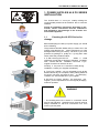
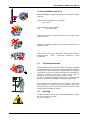
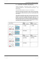
1
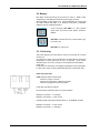
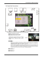
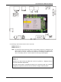
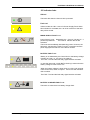
Power Supply Unit
HLS PS Series
HLSPS25-XPH and HLSPS50-XPH
User manual
8 APRIL 2010
HW_MN-DT-1305I_B
Information in this document is subject to change without notice
HLS PS25 & HLS PS50 User Manual
MN-DT-1305I_B
2
HLS PS25 & HLS PS50 User Manual
Contents
1
2
3
MN-DT-1305I_B
HLS PS Series Installation
4
1.1
Checking the HLS PS for damage
4
1.2
Pre-installation check list
5
1.3
Transient protection
5
1.4
Cleaning
5
1.5
Back Box HLS PS fixing
6
Functions and indicators
7
2.1
HLS PS25 and HLS PS50 characteristics
8
2.2
Battery
9
2.3
Fault relay
9
2.4
Control Unit connections
10
2.5
Indicator leds
12
Specification
14
3
HLS PS25 & HLS PS50 User Manual
1. POWER SUPPLIES HLS PS SERIES
INSTALLATION
The HLS PS Serie s i s ea sy to i nstall p roviding th e
recommended procedu res de scribed in this m anual are
followed.
Follow all installation instructions described in this
manual. Theses instructions must be understood
and followed to avoid damage to the S Series and
associated equipment.
1.1
Checking the HLS PS Series for
damage
Before attempting to install your power supply you should
do the following.
The procedure describe bellow tells you what to do in the
unlikely event that the sup
plied e quipment ha s been
damaged after leaving th e factory. Ho wever, if you have
problems re garding th e quality of a ny sup plied order
items, follow the procedure bellow:
1. If, after removing the HLS PS
Series , a visual
inspection reveals that it has bee n damaged, you MUST
NOT continue with the installation but conta ct you
supplier for advice on what to do next.
Similarly, if the prod uct is found to be faulty during
installation, contact your supplier immediately.
2. To aid you r supplier, you are requested to note all the
details relevant to your complaint, clearly stating details of
any techni cal probl ems, date of recei
pt, packaging
condition, etc. and forward this to your supplier.
3. Wh ere th e p roduct needs to be returned to your
supplier, you are requested to use the original packaging
wherever possible.
WARNING
• The b uilding whe re th e device i s connected should
have su rge and earth protections an d these sh ould be
easily a ccessible in o rder to di sconnect the unit from
mains by its two poles.
MN-DT-1305I_B
4
HLS PS25 & HLS PS50 User Manual
1.2 Pre-installation check list
Before selecting the location for the HLS PS Series, DO make
sure that:
a) The ambient temperature is in the range:
-5 ºC to 40 ºC
b) The relative humidity is bellow:
93%
(non-condensing)
c) DO NOT loca te th e e quipment w here i t is ex posed to high
levels of moisture.
d) DO NO T locate the e quipment where there ar e hi gh levels of
vibration or shock.
e) DO NOT s ite the HLS PS Series where there w ould be
restricted access
to the
internal equ ipment and
wiring
connections.
1.3
Transient protection
As with all solid state devices, this system may operate erratically
or c an be damaged i f sub jected to li ghtning-induced t ransients.
This equipmen t contains trans ient p rotection devic es. Al though
no sys tem is immune from l ightning transients an d in terference,
for thes e devices to func tion co rrectly, and to reduc e
susceptibility, this equipment must be earthed correctly.
The use of overhead or outside aerial wiring is not recommended
due to the increased susceptibility to nearby lightning strikes.
The HLS PS Series is wall m ounted in a posi tion, which a llows
clear v isibility of ind icator leds. The he ight above fl oor le vel
should be chosen such that t he indicators are just above normal
eye level (approximately 1.5 metres).
1.4
Cleaning
The HLS PS Series cas e may be clean ed periodically by wiping
with a soft, damp lint-free cloth.
Do not use solvents.
MN-DT-1305I_B
5
HLS PS25 & HLS PS50 User Manual
1.5 Back Box HLS PS Series fixing
When a suitable location has been found for installing the HLS PS Series, proceed as follows:
1. Hold th e b ack box a ssembly in the required p osition ag ainst the wall and m ark the p osition of th e
fixing holes, while ensuring the panel is level.
The drawing below shows the position of the fixing holes at the back box.
Do NOT use the back box as a guide when drilling!
2. Drill and plug the wall.
3. Prepare apertures required for cable access.
4. Screw the ba ck box to the wall using the fixing hole s
and appropriate-sized screws.
MN-DT-1305I_B
6
HLS PS25 & HLS PS50 User Manual
2. HLS PS Functions and indicators
FRONT PANEL:
FUS BAT FAULT
LOW BAT
NO BAT
BAT TEST
BAT CH
BAT DIS
IN ALARM
321087
1
2
MAX.
CPU
LEGEND:
=> ON
=> OUTPUT 1 FAULT
=> FAULT
=> OUTPUT 2 FAULT
=> MAIN SUPPLY FAULT
=> EARTH FAULT
=> BATTERY FAULT
=> BATTERY CHARGER
FAULT
=> OVERLOAD
=> SYSTEM FAULT
INTERNAL LEDS:
MN-DT-1305I_B
7
HLS PS25 & HLS PS50 User Manual
2.1 HLS PS25 / HLS PS50 characteristics
These Po wer Supplies Units are des igned to comply with th e
requirements of EN54-4 in order to provide fire control systems
with
backup supply.
The HLS PS Series operates at 115/230 Vac and 50/60 Hz.
Both Power Supply Units, HLS PS25 a nd HLS PS50, a re very similar :
they consist o f a 2x 65W, which means 1 30W in HL S PS50 and 1 x65W
in HLS PS25 and a standard module control which supervises the entire
power supply.
HLS PS25 an d HLS PS50 power supplie s provide 2.5 Amp and 5 Amp
respectively a nd 300mA to 600mA of th em are dedic ated to charg e
batteries. Th ese po wer su pplies are able to supply either up to 1.1 0
and 2.20 Amp current at each PSO1 a nd PSO2 out puts. This is the
default set up (DIP SW1 ON, up position). However, power supplies can
also supply all the current in only one outp ut by placing the DIP SW1 in
the down position, OFF. This way, all the current (2.20Amp or 4.40Amp
respectively) will be supplied through PSO1 output.
HLS PS25
SW1 up
SW1 down
HLS PS50
SW1 up
SW1 down
MN-DT-1305I_B
8
HLS PS25 & HLS PS50 User Manual
2.2 Battery
DIP SW2 al lows se lecting the m aximum cu rrent o f battery load,
depending on the batteries inside the power supply unit box.
With DIP SW2 in ON position (up), 7Amp/h batteries can be charged
at 3 00mA. When DIP SW2 is in OFF pos ition (down ), 20Amp/h
batteries can be charged at 600mA.
In this ex ample, DIP SW2 is in OFF position
(down) and the l oad current will be limited to
600mA.
DIP SW3. This DIP switch is in ON position (up).
For future use.
DIP SW4. For future use.
2.3 Fault relay
The Power Supply has a fault relay to repo rt any anomaly to a remote
control unit.
Any fault has a delay of 30 seconds from the fault signal to fault relay
confirmation, ex cept when there is a ma ins AC loss, which will be
indicated afte r an 8-minut e delay to avoid faults from intermittent
power cuts.
In stand-by, the fault relay is energized indicating its normal operation.
In case of any fault, the relay deactivates after the confirmation time.
Fault relay operation
FAULT switch with three terminals
Terminal 1 (left) C common
Terminal 2 (centre) NC or Normally Closed
Terminal 3 (right) NO or Normally Open
Fault relay operates as follows:
No supervision (without power) or in fault condition
Between C and NC —> continuity
Between C and NO —> open circuit
Operating with supervision without faults, i.e. in NORMAL STATE
Between C and NC —> open circuit
Between C and NO —> continuity
MN-DT-1305I_B
9
HLS PS25 & HLS PS50 User Manual
2.4 Control Unit Connections:
The following 4 connectors are placed at the top of the Control Unit:
FAULT (C) Fault Relay Common
FAULT (NC) Normally Closed Contact
FAULT (NO) Normally Open Contact
The faul t rel ay may be li nked to an analogue
input modu le to report any fault t o a third
equipment li ke a FACP ( Fire Alarm Control
Panel).
IN ALARM (+)
IN ALARM (-)
Alarm input to d isable, momen tarily, t he battery c harger and b e able to supp ly 300 600mA from ba ttery loa d to the ou tputs. Fo r th is, i t is necessa ry to l ink both IN
ALARM terminals by means of a jumper or short-circuit.
When this input is activated, the control unit will have an extra current of battery load
0.3 A or 0.6 A, depending on the DIP SW2 for outputs. Thus, if the power supply is in
Overload (Imax) sta te, the i ndication w ill d isappear by ac tivating this input, p rovided
that the excess current is the current which is supplying batteries.
PSO1 Output 1 (+)
PSO1 Output 1 (-)
PSO2 Output 2 (+)
PSO2 Output 2 (-)
MN-DT-1305I_B
10
HLS PS25 & HLS PS50 User Manual
The following is placed at the bottom of the Control Unit:
IN BAT Batteries (+)
IN BAT Batteries (-)
TEST The test butto n allows performing a led te st and makes a real test of batteries forc ing
them to supply current of 1 A approx. for a minute. In case batteries fail, a Battery fault
will be report ed. The HLS PS Series will supervise a utomatically t he battery ea ch 3
hours. If the battery load is in normal condition, the fault signal will disappear.
EN54 - 2
Section 8.2.4 requi res tha t any Earth faul t whi ch m ay affect an obligatory functi on
should be indicated independently.
The cable size should be calculated according to th e maximum l ength, the m aximum
voltage drop supported by devices and the minimum voltage of battery system.
MN-DT-1305I_B
11
HLS PS25 & HLS PS50 User Manual
2.5 Indicator leds:
ON Led
This led is ON when the Control Unit is powered.
Fault Led
Yellow led that is O N in case of a Po wer Supply Fault. When
this indication is a ctivated, the C an d NC contacts of the fault
relay will be closed.
MAINS SUPPLY FAULT Led
Power Sup ply is not detected by the Cont rol Unit and it i s
powered by batteries.
The internal led BAT-DIS is also
activated.
The led is ON immediately after detecting power. However, the
fault relay signal a nd th e FAULT led do n ot activa te until the
power supply fault remains for more than 8 minutes.
BATTERY FAULT Led
Battery is not detected by the Control Unit or the battery voltage
is below 22.4 Vdc, i.e., the 50% of its capacity.
The FAULT Led and the fault relay signal are also activated.
In case the internal le d LOW BAT is flashi ng it mea ns that the
battery voltage is close to 22.4 Vdc.
When the battery voltage is lower than 20.4 Vdc, both outputs,
PSO1 and P SO2, and th e Output 1 and 2 le ds will indicate a
fault condition.
The FAULT Led and the fault relay signal are also activated
BATTERY CHARGER FAULT Led
This led is on when there is a battery charger fault.
MN-DT-1305I_B
12
HLS PS25 & HLS PS50 User Manual
OUTPUT 1 FAULT Led
Indicates that the output 1 is not powered.
OUTPUT 2 FAULT Led
Indicates that the output 2 is not powered.
EARTH FAULT Led
Indicates an Earth Fault if one of t he wirings (+) o r (-) is lin ked to
earth.
If J3 is not connected, there will not be earth fault supervision.
Earth fault solution: Ma ke su re t hat there are n o links bet ween
Earth and Output 1 and 2 (+) y (-).
OVERLOAD Led
Indicates that the equipment exceeds the maximum current, 5 A.
A momentary peak voltage may be provide
d by disa bling the
battery load current in ca se of al arm by usin g the IN ALARM
connection, which switches the battery current of 3 00 or 600mA to
the outputs.
SYSTEM FAULT Led
Indicates that the Power Supply microprocessor is not operating
correctly.
MN-DT-1305I_B
13
HLS PS25 & HLS PS50 User Manual
3. Specification
Dimensions:
377 mm (w) x 408 mm (h) x 92 mm (d).
Power Supply Wattage:
130 W (HLSPS50) y 65 W (HLSPS25).
The HLSPS50 power supply has a total of 5Amp and 300mA
to 600mA of them are dedicated to charge batteries.
Input Voltage:
115 - 230 Vac; 50/60 Hz
Output voltage:
28 VDC +/-2% VDC (overload and short circuit protection).
Power Supply Outputs:
2
Terminals:
Removable terminals for 2.5 mm cable.
Optional conversion 2 outputs to 1 output:
Yes, using DIP SW1.
Maximum current per output*:
1.10 Amp (HLSPS25); 2.20 Amp (HLSPS50).
Maximum current using only one output
2.20 Amp (HLSPS25); 4.40 Amp (HLSPS50).
Alarm input:
By linking bo th terminal s with a jumpe r (or short-circuit), this
input allo ws the battery charger momentary di sablement in
order to provide extra 300/600 mA to the outputs.
Battery load current:
300 mA (7 Amp/hour) / 600 mA (17 Amp/hour).
80% of the Battery Capacity is charged in less than 24 h and
the 100% in less than 48 h.
Fault relay:
C, NC, NO contacts. 1 Amp/24Vdc maximum.
Energized in normal state.
State Indicators:
10 external leds (5 mm) + 7 internal (SMD).
Battery room:
For 2 x 22 Amp/hour
Conduit knockouts:
Ø 21 mm
Earth Fault Supervision:
Configurable (ON/OFF)
Standards:
Design according to EN5 4-4; UL19 50; TUV EN6 0950 a nd
EMC standards, EN55022, IEC1000-4-2,3,4,5 IEC1000-3-2.
Vibration test:
10-500 Hz 2G 10 min/1 cycle during 60 min. on each axle.
6 at the top of the back box
6 at the rear top of the back box
NOTE: Shield cables are required for power supply units’ connection.
MN-DT-1305I_B
14
HLS PS25 & HLS PS50 User Manual
MN-DT-1305I_B
15
Honeywell Life Safety Iberia
C/Pau Vila 15-19
E-08911 Badalona (Barcelona)
Spain
Tel.: +34 93 4973960 Fax: +34 93 4658635
www.honeywelllifesafety.es
Honeywell Life Safety:
Charles Avenue, Burgess Hill,
RH15 9UF West Sussex
Tel.: +44 (0) 1444 230 300
England
Berliner Straße 91
D-40880 Ratingen
Tel.: +49 2102-700 69-0
Deutschland
Avenue De L'Expansion 16 D
B-4432 Alleur
Tel.: +32 (0)4 247 03 00
Belgium
Via Grandi 22
20097 S. Donato Milanese (MI)
Tel.: +39 02 518971
Italia
www.honeywelllifesafety.com