1
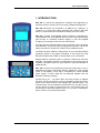
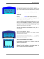
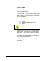
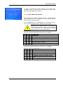
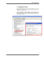
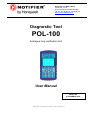
Honeywell Life Safety Iberia
C/Pau Vila, 15-19
08911 BADALONA (BARCELONA)
Tel.: 93 497 39 60 Fax: 93 465 86 35
www.honeywelllifesafety.es
Diagnostic Tool
POL-100
Analogue loop verification tool
User Manual
MN-DT-962
9 DECEMBER 2008
Information in this document is subject to change without notice.
POL-100 User Manual
INDEX
Page
1. INTRODUCTION................................................................................................ 3
2. MAIN MENU....................................................................................................... 4
3. AUTO LEARN (Autoprogramación).................................................................... 6
4. DEVICE POLLING ............................................................................................. 7
5. COMMUNICATIONS .......................................................................................... 9
MN-DT-962I
2
POL-100 User Manual
1. INTRODUCTION
POL-100 is a hand tool designed for analogue tool diagnostics by
which the faults in the fire loop can be easily located and diagnosed.
POL-100 electronics are contained in an ABS box (h: 19,05mm; w:
10,16cm x d: 3,27cm) with rubber protection and a stand to place the
device on a flat surface and visualize the display with a 45º angle.
POL-100 includes rechargeable Ni-MH batteries (1700mA/8.4V).
These batteries can be charged directly from the control panel battery
(they accept 12 Vdc/2Amp external supply) or with the supplied
charger by connecting it to the 220 Vac mains power.
The plug and play terminals allow an easy connection to the analogue
loop. Moreover, connection clips are supplied so that POL-100 can be
easily connected to any base or module at any installation point.
The USB connector allows the transmission of up to 200.000 registers
previously stored or the graphic illustration of the entries by using
Windows software that is able to communicate up to 115.200 bps.
Display features: 320x240 pixels, 81,4x61mm visible area and blue
backlight. The display shows the configuration of 99 sensors and 99
modules, information about the type of device, total and subtotals of
polled devices.
POL-100 is turned on by pressing the power key (under the F1 key), if
batteries are charged. The battery status is displayed on the top right
corner of the display. If POL-100 is connected to a 12Vdc external
power supply, a mains cable will be displayed together with the
indication of battery charging
Function keys (F1 – F4) allow direct and easy access to different
functions. Arrow keys allow the user to navigate through the menus,
sensor and module screens and highlight the required option. The
required option can be selected with the Enter key and the Esc key
can be used to go back to the previous menu. The number keys can
be used also to select the different menus, e.g. to enter “1.Multímetro”
menu, number 1 key should be pressed.
.
MN-DT-962I
3
POL-100 User Manual
2. MAIN MENU
1.
2.
3.
4.
5.
6.
MULTIMETER
AUTOLEARN
SAMPLING DEVICES
REGISTER LOOP
CONFIGURATION
COMMUNICATIONS
The option 1 of Main Menu, Multimeter, allows the user to check the cable resistive values and
ensure that the loop is closed and the values are within the range recommended by manufacturer.
Multimeter menu has three options:
1. RESISTANCE
2. EARTH
3. VOLT/CURRENT
Option P/1/1 MULTIMETER, RESISTANCE
When selecting RESISTANCE, the following data appear:
R POSITIVE --- ohms
R NEGATIVE --- ohms
If there is continuity at both loop ends, the RESISTANCE
display will show the resistive value of each of the cables.
These values should be below 20 ohms, up to 40 ohms
altogether, according to manufacturer’s specifications.
A 1.5mm2 cable has a resistance of 13.3 ohms / Km, while a
2.5mm2 cable has lower resistance, 7.9 ohms / Km approx.
Resistive values vary depending on the cable length, according
to the following table:
2
1.5 mm cable
2
2.5 mm cable
500 m 750 m
7
10
4
6
1000 m
13
8
1250 m 1500 m 2000 m 2500 m
17
20
27
33
10
12
16
20
3000 m
40
24
For example, the resistance for a 1.5mm2 cable section and 1500 m cable length is 20 ohms per
cable (40 ohms both). A higher distance with a 1.5mm2 is not recommended because the total
resistance would be more than 40 ohms.
MN-DT-962I
4
POL-100 User Manual
When the resistance exceeds 99 ohms, the display will show “- - “
If the cable screen is linked to S (Screen) terminals, Out and In, the
user can check resistive values with positive terminal by pressing
F2.
F2 key =>
Screen + (Res. SCREEN POSITIVE.)
F3 key will show the resistance between the cable screen and
negative loop.
F3 key =>
Screen - (Res. SCREEN NEGATIVE.)
The cable screen must not have any link between positive and
negative loop. If a value different to infinitive (-.--) is showed on the
POL-100 display, please verify the links.
Finally, the resistance value between both screen terminals, S out
and S In, will be calculated by pressing F4. The cable screen
section is lower than negative and positive loop cables, therefore
the values for this screen will double the positive and negative loop
cable values. If positive loop has 15 ohms resistance, the screen
resistance value will be 25-40 ohms approx.
When the screen resistance value displayed is lower than any
circuit, this means that the cable screen has no continuity and “- -“
will be displayed.
Option P/1/2 MULTIMETER, EARTH
Option 2 Earth will display the resistance value between the cable
screen and the earth connector.
The cable screen must not be linked to Earth. If “- . –“ is displayed,
please check the point where the loop screen is in contact with the
building earth in the installation.
Option P/1/3 MULTIMETER VOLT/CURRENT
By selecting Option 3 VOLTAGE/CURRENT, the user can verify
the current drawn from devices at 24, 5 and 0 Vdc and see the
voltage drop in the loop return.
By pressing F1 key, the Loop Out terminals will have 24Vdc and
the return voltage and the required current of loop devices will be
displayed. This current, although can be 20-100mA initially, will
have to be lower after this momentary peak current.
MN-DT-962I
5
POL-100 User Manual
3. AUTOLEARN
This option will display sensors and modules installed and
addressed in the loop. The display will show the type of total
devices found and their addresses.
F1 key allows the user to start an “Autolearn”. This is an automatic
function which carries out constant samplings from 00 to 99
addresses looking for any change since the last reading.
Whenever a device is found out, the device type will be displayed
next to the device address:
•
•
•
•
•
•
•
(T)
(I)
(O)
(L)
(P)
(M)
(S)
Thermal
Ionic
Optical
Laser
Pinnacle
Multicriteria, Optical/Thermal or Smart 3
Smart 4
When there is a loop short-circuit, this symbol
will
be displayed next to the battery status indication.
Moreover, buzzer will activate until this fault is cleared.
When there are two or more sensors or two or more modules with
the same address, this symbol “-“ will be displayed next to the
address device. In order to identify the device with the wrong
address, the user should activate the “Manual learn mode” option
and, select with the key arrows the duplicated addresses.
F1 changes the learn mode: from MANUAL LEARN (only one
polling) to AUTO LEARN (constant polling).
If the MANUAL LEARN option has been selected by pressing F2, a
new short polling will show changes between the last and the
current reading.
MN-DT-962I
6
POL-100 User Manual
Once the manual learn has been finished, the device addresses
can be verified. By pressing the arrow keys, we will move through
the different addresses and when one of them is selected, the
POL-100 sends an order to the device with that address so that its
LED lights on.
By pressing F3 key, the selected device is added to the
SAMPLING DEVICES screen. This screen will show up to 10
devices.
We can get access to the SAMPLING DEVICES screen and
visualize the PW pulses of the selected device, by pressing the
Enter key or going back to the main menu and press 3. SAMPLING
DEVICES.
4. SAMPLING DEVICES
This option allows the user to visualize the response value range of
the selected devices. Up to ten devices can be displayed. Devices
visualized in this screen can be added or cleared manually by
pressing F1 and F2 respectively. That means that from this menu,
when the user presses F1 a new device will be added to the polling
list, always with the next address. For example, if the device with
address 40 is selected and we press F1, the sensor 41 will be
added. The addresses from 100 to 199 belong to modules (from 00
to 99). Thus, if sensor 99 is selected and F1 is pressed, the
following device added will be 100, which stands for module 00.
The devices displayed on this screen can be added directly in the
AUTOLEARN screen by pressing F3 on the required address.
Devices can also be added or cleared from the screen by pressing
F1 and F2 respectively.
Each line provides information of each selected device and the left
column can display the response current value or the alarm
analogue value %. To change from one to another value, F4 key
must be pressed.
POL-100 carries out a polling of the devices displayed every 3
seconds and record their values at the same time:
By pressing F3 key, the user can change the display mode of the
Sampling devices screen:
• CURRENT: The display shows real time values
• LOWEST: The display shows the lowest value from the
first access to this menu.
• HIGHEST: The display shows the highest value of each
saved pulse.
• AVERAGE: The average value is displayed
MN-DT-962I
7
POL-100 User Manual
In order to change the device address or to obtain more
information about a specific device, the ENTER key should be
pressed and the display will change to:
P / 3 / 1 CONF- SAMPLING DEVICES
This display shows the device address. The user can highlight and
edit the address in order to change it, from 00 to 99 for sensors
and from 100 to 199 for modules.
If the “COMMAND” line is highlighted, the “command” sent by
POL-100 to the specific sensor or module can be modified.
Depending on the selected values, it is possible to
activate output modules, sounders, electromagnets
or even extinctions. Any output that may lead to
unwanted actions must be disconnected.
POL-100 can send the following “commands” to a sensor:
C0 C1 C2 COMMAND
1
1
1
0
1
0
0
1
1
1
0
1
0
1
1
1
0
1
User, Bits can be edited
Display type, PW5 value is displayed
Led Off, the led is turned off
Led On, The led is turned on steady
Alarm Test, Test Alarm, the device electronics
simulates an alarm condition
Normal
POL-100 can send the following “commands” to a module:
C0 C1 C2 COMMAND
MN-DT-962I
1
1
1
0
1
0
0
1
1
0
1
1
0
1
0
1
0
1
User, Bits can be edited
Display type, PW5 value is displayed
Relay Off, the output is de-energized
Led is activated but the output is not.
ATTENTION. Output is energized, internal
relay
Normal
8
POL-100 User Manual
5. COMMUNICATIONS
This option allows the POL-100 to communicate with a PC. The
installation of USB driver is required so that Windows enables the
serial port for communication.
Once the USB driver has been installed, click on Control Panel =>
System => Hardware => Device Manager. The USB Serial Port will
be displayed, with the number of the first serial port available in the
PC, in this case COM1.
MN-DT-962I
9
POL-100 User Manual
Honeywell Life Safety Iberia
Headquarters in Barcelona: Tel.: 93 4973960 Fax: 93 4658635
Office in Madrid: Tel. 91 1314800 Fax: 91 1314899
Office in Seville: Tel 95 4187011 Fax: 95 5601234
Office in Bizkaia: Tel.: 94 4802625 Fax: 94 4801756
Office in Portugal: Tel.: 00 351218162636 Fax: 00 351218162637
www.honeywelllifesfety.es
MN-DT-962I
10