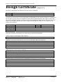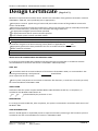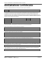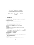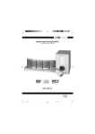
1
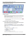
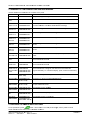
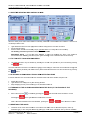
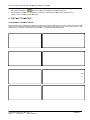
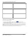
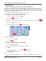
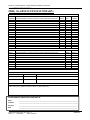
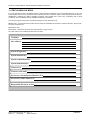
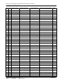
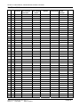
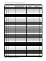
USE ER MAN M NUA AL, MA AINT TEN NAN NCE GUIDE E& LOG G BOO B K INFINITY 8 USER MANUAL, MAINTENANCE GUIDE & LOG BOOK Contents 1. FIRE ALARM CONTROL PANEL SAFETY ISSUES ........................................................................ 3 2. THE PURPOSE OF A FIRE ALARM SYSTEM ................................................................................. 3 3. USER RESPONSIBILITIES & MAINTAINENCE OF THE FIRE ALARM SYSTEM, INCLUDING THE FACP & ITS INTEGRAL PSE ........................................................................................................ 4 4. PANEL INDICATIONS & CONTROLS .............................................................................................. 5 4.1 GENERAL CONTROLS .............................................................................................................. 5 4.2 ACCESSED CONTROL (AVAILABLE TO AUTHORISED USERS ONLY) ................................ 5 4.3 SUMMARY OF LED COMBINATIONS AND THEIR MEANING................................................. 6 4.4 CHECKING THE PANELS INDICATION LEDS ......................................................................... 6 5. THE FIRE CONDITION ..................................................................................................................... 7 5.1 HOW THE INFINITY 8 INDICATES AN ALARM ........................................................................ 7 5.2 TO TURN OFF THE ALARM SOUNDERS ................................................................................. 7 5.3 A SECOND ALARM SIGNAL FROM A NEW DETECTION ZONE ............................................ 7 5.4 TURNING ON THE ALARM SOUNDERS FROM THE FACP (I.E. TO EVACUATE THE BUILDING). ....................................................................................................................................... 7 5.5 RESETTING THE PANEL ........................................................................................................... 7 6. THE FAULT CONDITION .................................................................................................................. 8 6.1 DIFFERENT TYPES OF FAULT ................................................................................................. 8 6.2 WHAT TO DO IF A FAULT CONDITION OCCURS ................................................................... 9 7. DISABLEMENTS ............................................................................................................................. 10 7.1 REASONS FOR DISABLING CERTAIN PARTS OF A FIRE ALARM SYSTEM. ..................... 10 7.2 TO DISABLE A ZONE AND/OR EXTERNAL SOUNDERS. ..................................................... 10 7.3 TO ENABLE A ZONE AND/OR EXTERNAL SOUNDERS. ...................................................... 10 8. USING SOUNDER DELAYS ........................................................................................................... 11 8.1 WHAT IS A SOUNDER DELAY ................................................................................................ 11 8.2 SOUNDER DELAY SETTING ................................................................................................... 11 8.3 HOW THE PANEL INDICATES SOUNDER DELAY ................................................................ 11 8.4 A FIRE ALARM CONDITION ON A DELAYED PANEL ........................................................... 11 8.5 OVERRIDING A DELAY IN THE EVENT OF A GENUINE FIRE ALARM................................ 11 8.6 RESET THE SYSTEM IN THE EVENT OF A FALSE ALARM ................................................. 11 8.7 TO TURN OFF THE SOUNDER DELAY .................................................................................. 11 9 ZONE TEST ...................................................................................................................................... 12 9.1 Why use Zone Test ................................................................................................................... 12 9.2 TO PROGRAMME ZONE IN TEST .......................................................................................... 12 9.3 NOTES ON TEST MODE.......................................................................................................... 12 10. SYSTEM DESCRIPTION .............................................................................................................. 13 11. FIRE ALARM LOG BOOK ............................................................................................................. 14 12 COMMISSIONING THE SYSTEM, INCLUDING P.S.E. ................................................................ 18 12.1 DESIGN, INSTALLATION & COMMISSIONING CERTIFICATES ......................................... 18 Approved Document No: GLT-201-7-2 Issue: 1.2 Authorised: Date: 27/3/2012 PAGE 2 INFINITY 8 USER MANUAL, MAINTENANCE GUIDE & LOG BOOK 1. FIRE ALARM CONTROL PANEL SAFETY ISSUES There is no need to open this fire alarm during normal operation. Any work carried out on this system must be performed by a competent person who is familiar with this type of system. This equipment will operate safely provided it has been installed correctly in compliance with the Installation Manual. It is recommended that the system is serviced frequently. It is customary to arrange a regular maintenance contract with a competent organisation. (Ask the installation company for recommendations). The system needs a thorough maintenance check annually at the very minimum. If any part of this Fire Alarm Control Panel becomes damaged, contact the company responsible for system maintenance to arrange repair / replacement. CE European Union Directives Conformance Statement This product has been manufactured in conformance with the requirements of all applicable EU Council Directives. The Declaration of Conformance for this product is located at the following Address: GLT Exports Ltd, 72-78 Morfa Road, Hafod, Swansea, SA1 2EN, United Kingdom 2. THE PURPOSE OF A FIRE ALARM SYSTEM A Fire Alarm System is used to provide an early warning of a fire, so that the property can be evacuated and the fire extinguished if it can be safely tackled, or the local fire brigade called, according to the company evacuation procedure. Alarms can come from Smoke or Heat Detectors, or manually be a person operating a Manual Call Point. Split the system into Zones, each covering a different area of a building. This will indicate which area of the system is giving the alarm (or fault). During an alarm, the panel will start its sounders, and indicate which zone has the fire. It will also activate its auxiliary relay. Fault Monitoring All circuits must be checked for line integrity. If a part of the system has a problem which may affect its operation, a fault warning must be given by the fire alarm panel (LED & buzzer indication). The fault relay will also activate. Disablements An engineer may be required to work on part of a system, while the system is still active (e.g. extending a detection zone). During such circumstances, it would be advisable to disable that zone, so that it will not give false alarms. Similarly you may wish to disable a zone that has a fault that has not been fixed, or a zone covering an area with a temporary unusual environment, such as an area which is dusty because of construction work etc. Delays In public places, it may be desirable to delay the activation of an alarm until the responsible person has verified the cause of the alarm. (This would avoid a panic evacuation caused by a smoky room, or a maliciously activated call point.) On verification of the alarm, the sounders can be started by pressing the override button, or the panel can be reset in the case of a false alarm. If a delay has been set, it must be recorded on the system configuration chart at the back of this manual. Power Supply Equipment- General Description. The INFINITY 8 FACP has an integral linear power supply capable of supplying 1.2 amps in total. It contains a current limited output for charging sealed lead acid batteries (3.4 Ah maximum). The PSE is monitored for main supply failure, the battery not taking a charge, low battery voltage and resistance. If the battery voltage drops below approximately 20VDC (a fault condition), the battery charging current will be turned off, thus stopping charging. This PSE is only capable of supplying power to the CIE, and is not designed for any other use. Approved Document No: GLT-201-7-2 Issue: 1.2 Authorised: Date: 27/3/2012 PAGE 3 INFINITY 8 USER MANUAL, MAINTENANCE GUIDE & LOG BOOK 3. USER RESPONSIBILITIES & MAINTAINENCE OF THE FIRE ALARM SYSTEM, INCLUDING THE FACP & ITS INTEGRAL PSE According to the British Standard Code for Fire Detection and Alarm Systems for Commercial Buildings (BS5839: Pt 1: 2002), the owner or person having control of the premises should appoint a responsible person to oversee the effective operation of the Fire Alarm System (Clause 47.1). Below is a summary of the main functions the “Responsible Person” is expected to carry out. This summary is not intended to replace Section seven (User responsibilities) of BS5839: Pt 1: 2002 (available from BSI, or your local library). It is meant to give a brief outline of user responsibilities for the safe upkeep of the Fire Alarm System. The number in brackets shows the relevant BS5839: Pt 1: 2002 clauses. The responsible person must:1. 2. 3. 4. 5. Have sufficient authority to carry out the duties associated with being the responsible person (47.2.a) Check the system at least once every 24 hours to ensure there are no faults present (47.2.b) Ensure there are arrangements for testing and maintaining the system (47.2.c) Ensure the log book is up to date, and available for inspection (47.2.d) Instruct all relevant occupants on the basic operation of the system, including start evacuation, silence alarms, silence faults and system reset (47.2.e) 6. Take appropriate action to limit the rate of false alarms (47.2.f) 7. Ensure that all detectors and manual call points remain unobstructed at all times (47.2.g) 8. Liaise with maintenance personnel to ensure that cleaning, maintenance or building work does not interfere with the functioning and reliability of the fire alarm system (47.2.h). 9. Ensure any changes to the system are recorded with updated drawings, operating instructions etc (47.2.i) 10. Ensure that there are spare parts (especially Call point elements) held on site (47.2.j.1&2) With the Infinity 8 Range of Fire Alarm Panels, we recommend the following tests are carried out: Daily Inspection Check that the green Power LED is lit. If there are any yellow fault LEDs lit, or the green Power LED is not lit, report the fault(s) to the designated site maintenance engineer. Weekly Test (you may wish to temporarily disconnect the Aux relay during the following Tests) Set off a manual call point or sensor to test the Fire Alarm panel responds and all the sounders activate. Do not test the same device each week. Test a different zone each week using a different call point or detector so that eventually, all the devices will be tested. Reset the System by pressing (Stop sounders, Silence fault tone, Reset). Enter access code. Press the LED Test button. Check that all LEDs light, and the buzzer sounds Check that no call points or fire detectors are obstructed in any way. (e.g. New furniture or decorations) Quarterly Test (to be carried out by authorised service personnel only) Check that any servicing or repairs required by all previous logbook entries has been undertaken. Visual inspection of the batteries and connections. Check the alarm sounders work on battery only. Activate a device from each zone to test the fire alarm. (As per weekly test). Annual Test (to be carried out by authorised service personnel only) Check every detector, call point, sounder and all auxiliary equipment for correct operation. Check Cage output Voltage (30VDC), Charger Voltage (27.6Vnormal and 29.4V fast charge) & Battery Voltage (25-27V) Every Five Years (to be carried out by authorised service personnel only) Carry out a complete wiring check in accordance with the testing and inspection requirements of the relevant National wiring regulations (in the UK this is the IEE Wiring Regulations). The Batteries should be replaced because SLA batteries have a working life of 5 years. Approved Document No: GLT-201-7-2 Issue: 1.2 Authorised: Date: 27/3/2012 PAGE 4 INFINITY 8 U USER MANUA AL, MAINTENA ANCE GUIDE E & LOG BOO OK 4. PANEL L INDICAT TIONS & CONTROLS C S Two levels off control are available a to the e User(s) of th his Fire Alarm Panel. 4.1 GENER RAL CONTRO OLS Whe en the Panel is in its Normal state, th he indicator lights on the front of the enclosure giv ve a com mprehensive overview o of th he System’s ccurrent status.. Any Fire an nd Fault condditions are cle early disp played, and an ny disablemen nts highlighted d. For detailed d descriptions s of what eachh indicator means, plea ase refer to the e table on the opposite pag e. e only functions that can be performed by the User whe en the Panel is s in its Normall state are: The Overriding any a Delays, wh hich may have e been programmed into the e Panel by preessing the Override Sou under Delay button. b Putting the Panel P into the Accessed sta ate – see below w. 4.2 ACCES SSED CONTR ROL (AVAIL LABLE TO A AUTHORISED USERS ONLY) O avoid unautho orised change es to critical p arts of the Firre Alarm Systtem, controls such as silencing To a the Sounders, ressetting an Ala arm condition a and implemen nting Disablem ments are onlyy accessible via v a ure method off entry which puts p the panell into the Acce essed state. secu put the Pane el into the Accessed State e: Entre the access a code (1245) then prress To p . To exit acce essed state prress thre ee times. If the e wrong code is entered threee times, then n the LED D display will light a combination of LED’ss. If this happe ens you will need to contacct GLT Exports s for the code. anging the Ac ccess Code Cha (control Enable lit) 1. Enter the currrent access co ode and presss 2. Press 3. 4. Re-type the access a code and a press Type the new w code 5. 6. Press f 5 seconds for The will give a confirmation n beep. New ccode is active f 3 seconds panel will bee for ep ow to use the accessed a conttrol can be fou und on Pages 8 to 11 of thiss User Manua al. Information on ho Approved Do ocument No: GLT-201-7-2 G Date: 27/3/2012 Issue: 1.2 Authorised: PAGE 5 INFINITY 8 U USER MANUA AL, MAINTENA ANCE GUIDE E & LOG BOO OK 4.3 SUMMA ARY OF LED D COMBINATIONS AND D THEIR MEA ANING Use the table e below to dete ermine the condition of the panel. LEDs LIT POWER LED CON NDITION CONSTAN NT GREEN TUS PANEL STAT The panel is ssupplied with power, p and ha as no faults / fiires (System Normal) N GEN FLT ONLY FLASHING G YELLOW GEN FLT & T SUPPLY FLT FLASHING G YELLOW FLASHING G YELLOW There is a pro oblem with eith her the mains supply or the battery backu up. (Consult Insta allation manua al for details off flash meaninngs) GEN FLT & EARTH FLT FLASHING G YELLOW CONSTAN NT YELLOW There is a wirring problem. One O of the cab bles is touchinng the earth sc creen. GEN FLT & ZONAL FLT CONSTAN NT YELLOW FLASHING G YELLOW There is an op pen circuit fau ult in the wiring g of the zone i ndicated. GEN FLT & ZONAL FLT GEN S/C FLASHING G YELLOW FLASHING G YELLOW FLASHING G YELLOW There is a sho ort circuit faultt in the wiring of the zone inddicated. GEN FLT & SND FLT FLASHING G YELLOW FLASHING G YELLOW There is an op pen circuit fau ult in the wiring g of one or botth of the sounder circuits GEN FLT & SND FLT GEN S/C FLASHING G YELLOW FLASHING G YELLOW FLASHING G YELLOW There is a sho ort circuit faultt in the wiring of one or bothh of the sounder circuits GEN FLT & SYSTEM FLT T NT YELLOW CONSTAN CONSTAN NT YELLOW A processor fa ault has occurrred. To reset,, If problem peersists, consullt your dealer. GEN FIRE ONLY NO LED A manual eva acuation has occurred. o The sounderss will be active e. GEN FIRE & ZONE FIRE CONSTAN NT RED CONSTAN NT RED A fire has occcurred in the zone indicated. The sounderss will be active e. GEN FIRE & ZONE FIRE & GEN DISABL LE & DEL CONSTAN NT RED CONSTAN NT RED CONSTAN NT YELLOW CONSTAN NT YELLOW A fire has occcurred in the zone indicated. The sounderss have a delay y set, and will become activee after the programmed d delay. To override the display, press oveerride sounder delay. GEN DISABL LE FLASHING G YELLOW (FAST – 4 HZ) H The panel is rready for selec cting disable or o test mode GEN DISABL LE FLASHING G YELLOW (SLOW – 0.5 HZ) The panel is i n SELECT DISABLEMENT T MODE GEN DISABL LE FLASHING G YELLOW ZONE DISABLE E (SLOW – 0.5 HZ) The user is sccrolling throug gh zones to select which onee to disable/orr user has just enab led the zone. GEN DISABL LE CONSTAN NT YELLOW ZONE DISABLE E CONSTAN NT YELLOW The indicated zone is disab bled. GEN DISABL LE CONSTAN NT YELLOW DEL CONSTAN NT YELLOW The Sounderss are delayed by the amoun nt set on the rootary switch. GEN TEST ZONE DISABLE E G YELLOW The indicated zone is in Test Mode. FLASHING FLASHING G YELLOW (VERY SLO OW – 0.25 HZ) 4.4 CHECK KING THE PA ANELS INDICATION LE EDS To test panell LED’s press butto on. All the LED Ds on the fron nt panel will lig ght, and the paanel’s internal buzzer will allso sound. Thiis function is available a at Le evel 1. Approved Do ocument No: GLT-201-7-2 G Date: 27/3/2012 Issue: 1.2 Authorised: PAGE 6 INFINITY 8 U USER MANUA AL, MAINTENA ANCE GUIDE E & LOG BOO OK 5. THE FIRE COND DITION 5.1 HOW TH HE INFINITY Y 8 INDICAT TES AN ALA ARM When the Inffinity 8 Fire Alarm Panel is set s into alarm m by a Detecto or or Manual Call C Point locatted in a zone that is not already in n alarm it will: - Light the e General Fire e LED and app propriate Zone e Fire LED(s) on o the front off its enclosure Sound In nternal buzzerr Start the e Alarm Sound der and Auxilia ary output, (prrovided there is no Delay se et on the soundders). The buillding evacuation procedure should no ow be followe ed. IMPORT TANT NOTE: If a zone has h been dissabled, it can nnot be trigge ered into Alarrm. This shou uld be remembered when dissabling part off the system. ((See Disabling g zones or sou unders later inn this manual). 5.2 TO TUR RN OFF THE E ALARM SO OUNDERS The Alarrm Sounders may be silenc ced by enterin ng the access s code (sectio on 4.2) and m momentarily pressing the button. The Alarm So ounders will cease to sound d but the light((s) for the Zon ne(s) in Alarm and the red G General Fire lig ght will stay lit. The Auxiliary Fire e relay will rem main active. (T The Panels intternal buzzer can also be ssilenced by pressing the b button. 5.3 A SECO OND ALARM M SIGNAL FROM A NEW W DETECTIO ON ZONE If another dettection Zone is activated aftter the Alarm S Sounders hav ve been silenc ced, the panel will: - Restart tthe sounders Light the e Zone Fire LE ED(s) for any new n Zone(s) in n alarm Keep the e light(s) for th he previous Zo one(s) in fire, a and General Fire F lit. 5.4 TURNIN NG ON THE ALARM SO OUNDERS FR ROM THE FA ACP (I.E. TO O EVACUAT TE THE BUILDING)). Enter co ode and press g the Pressing , momen ntarily pressing g the will cause the e Alarm soundders to sound. button again will w Silence the e Alarm Sounders. unders have been disabled, pressing the Note: If tthe Alarm Sou or button w will have no efffect. 5.5 RESETT TING THE PANEL P Check th he cause of the alarm activa ation. If the ca ause of the ala arm was an ac ctivated call pooint, reset it (if resettable type), or fit a new glass element e (if glasss type). If the e cause of the alarm was byy detector activ vation Approved Do ocument No: GLT-201-7-2 G Date: 27/3/2012 Issue: 1.2 Authorised: PAGE 7 INFINITY 8 U USER MANUA AL, MAINTENA ANCE GUIDE E & LOG BOO OK (e.g. coo oking smoke), the smoke will have to be ccleared from the room beforre the panel caan be reset. Reset R the pane el by pressing the after a the sound ders and pane el buzzer have e been silenceed. If the calll point is still active, a or the detector d is stil l smoky, this will w cause ano other alarm strraight after the e panel is reset, so will set s off alarm bells b again. 6. THE FA AULT CON NDITION 6.1 DIFFER RENT TYPES S OF FAULT T The fire alarm m monitors itsself, and any equipment e con nnected to it, for f any faults that t can occurr. If a fault occ curs, the Pane el responds by activating its Internal buzz zer and lighting g the General Fault light and any other Fault light(s) relevant to the ult. The Panel’s Fault relay will also activa ate. Typical fa aults are desc cribed below: particular fau General Fault The Gen neral Fault LED D is a commoon indicator tha at flashes when the ere is a Fault on o any part off the Fire Alarm m Systems. It is usually lit in tande em with at leaast one other fa ault light which co onveys more precise p informaation on the ty ype of Fault dettected. Zone Fa ault The relevant Zone Fau ult light flashees when there is a wiring prroblem on a Zo one or detectoor has been re emoved from its base. It should be noted that anyy alarms raise ed on the fault zon ne(s) may not be recognisedd by the Fire Alarm A Panel until the Fault Conditio ons have beenn cleared. It ca an take up to 60 secon nds from repairing a fault foor the display to t clear. Short Circuit Fault If the Fault is a short circuit c fault, theen the S/C LE ED will be flash hing. This S/C C LED will be flashing for S/C C faults on the e zone and soun nder circuits. It can take up to 60 seconds s from repairin ng a fault fo or the display to t clear. Power Supply S Fault The Pow wer supply Fau ult light flashess when the Ma ains supply has failed or the stand dby batteries oor its charger is faulty. If the main ns supply fails,, the panel wil l only operate e for the standby period dictate ed by the size of the batterie es fitted. If the batte eries or charge er fails at the ssame time as the Mains, the Pane el will be inope erative. Approved Do ocument No: GLT-201-7-2 G Date: 27/3/2012 Issue: 1.2 Authorised: PAGE 8 INFINITY 8 U USER MANUA AL, MAINTENA ANCE GUIDE E & LOG BOO OK System Fault The Sys stem Fault LE ED and Gen fault lights when the Pa anel’s micro-processor erference, or iff has Reset, typically affter excessive electrical inte ents of its mem mory have beeen corrupted. This fault can n the conte only be cleared c by turn ning the key sswitch from offf position to control enable e position n and then bacck to the off position again. If the fault re-occurs with hin two minutees, this is indic cative of a corrupt memory m and expert e advice sshould be sought. Earth Fa ault s constant wheen the panel detects d an earrth The Eartth Fault light is fault (sho ort circuit to ea arth) on the w wiring to any pa art of the control panel. p Sounder Fault under status lig ght flashes whhen there is a wiring fault The Sou on the Sounder Circuits. Dependingg on where the fault urred, one or all a of the Alarm m Sounders may m no longer has occu be opera ative. If the fault is a short circuit c fault, theen the S/C LE ED will also be flashing 6.2 WHAT T TO DO IF A FAULT CON NDITION OC CCURS If a fault occu urs, the respon nsible person should: Enter the e access code e and press to enable ed controls and d press to silence tthe fault buzze er. Write do own the fault (s) in the Log g Book at the e back of this Manual. Take appropriate te action to co orrect the fault (Usually by contacting g the service engineer) e On the Infiniity 8 panel, th he fault indica ations (exceptt system faultt) are non lattching. That iss, when the fault f has been cleared, the ffault indication n will turn off. When all fau ults have been n cleared, the panel will retuurn to its quie escent (normal) condition. dicator light fo r that Fault is s automatically y turned off. If all Faults are cleared, the When a faultt has been rectified the ind General Faullt light will go out o and the Pa anel’s Internall Sounder will be silent (if no ot already mutted). Approved Do ocument No: GLT-201-7-2 G Date: 27/3/2012 Issue: 1.2 Authorised: PAGE 9 INFINITY 8 U USER MANUA AL, MAINTENA ANCE GUIDE E & LOG BOO OK 7. DISABLEMENTS S 7.1 REASO ONS FOR DIS SABLING CERTAIN PA RTS OF A FIRE F ALARM M SYSTEM. orarily disable ed (i.e. switched off) to suitt prevailing co onditions. Fo or Certain partss of this Fire Alarm Panel can be tempo example, if there is a riskk of a False Alarm A in a zon ne, for examp ple, from vehic cle exhaust s moke in a loa ading bay, it is i e during the riisk period and d then enable it again afterw wards. During a disablemen nt possible for tthe user to dissable that zone of a zone(s), no fire or fau ult signal will be b processed ffor that zone(s). Only zone e(s) in a non-aalarm state ca an be disabled d, e cannot be disabled. that is zones already in fire nders can also o be disabled as could be re equired in cerrtain conditions s. External soun 7.2 TO DISA ABLE A ZONE AND/OR R EXTERNAL L SOUNDER RS. 1. Enter the access co ode (default 12 245) and presss 2. Hold the Disable 3. Type tthe number off the zone you u want to disa ble. If you want to disable a sounder preess “Start Soun nders” button n 4. e selected zone or sounder. Press to disable the 5. To exiit the disable mode, m Hold the Disable button for f 3 seconds button fo or 3 seconds d Zones. Showing all the Disabled 1. access code and a press Enter a 2. Press Disable 7.3 TO ENA ABLE A ZON NE AND/OR EXTERNAL L SOUNDER RS. 1. a press Enter access code and 2. able button forr 3 seconds D Disable and zone light flash Press and hold Disa 3. Press 4. n for 3 second ds Disable Press and hold the disable button 5. Press es out LED goe three tim mes to exit NOTES: bling or enablin ng zones 2, 3 3, 4, 5, 6, 7 an nd 8 is only av vailable if thesse zones are present on the The option of disab panel Approved Do ocument No: GLT-201-7-2 G Date: 27/3/2012 Issue: 1.2 Authorised: PAGE 10 INFINITY 8 U USER MANUA AL, MAINTENA ANCE GUIDE E & LOG BOO OK 8. USING SOUNDE ER DELAY YS 8.1 WHAT IIS A SOUND DER DELAY In certain circcumstances itt may be desirable to have a delay betw ween the panel detecting a ffire, and starting its externa al sounders, to allow the resp ponsible perso on to check th he cause of the e alarm, to sto op building evaacuation by an n obvious false e cause of the e Alarm is foun nd to be a tru e fire hazard, the Delay ca an be overriddden and the Alarm Sounderrs alarm. If the activated imm mediately. Alternatively, in the t case of a ffalse alarm, th he Panel can be b reset. 8.2 SOUND DER DELAY SETTING On the Infinitty 8 panel, the e sounder delay can be pro ogrammed on zones 2 – 8 (zone 1 cannoot have a dela ay). That is, all a zones will be e delayed by the same amo ount. The dela ay can be set between 1 minute and 10 m minutes, or the e delay can be left off (soun nders activate immediately)). Changing th he delay time should only be done by tthe engineer responsible r fo or setting up the e system. But turning the de elay on or off ccan be done by b the user. activate Soun nder delay Activate/Dea Entter Access cod de (default 1245) Pre ess bu utton Pre ess bu utton again to deactivate so ounder delay 8.3 HOW TH HE PANEL INDICATES I SOUNDER DELAY If a Delay ha as been progrrammed into the Panel, the e General Dis sablement & DEL(AY) LED Ds will be lit. When a zone processes an n alarm signall, the panel will indicate fire e in the usual way, but the sounders s will not be active until the dela ay period has e expired. To override o this delay, press Delay Overrid de Switch, wh hich will causse the externa al sounders to t energise. If tthere is no delay programmed, the Delayy Override Switch has no fun nction. 8.4 A FIRE ALARM CO ONDITION ON A DELAY ED PANEL anel, the panell will: When an alarm occurs on a Delayed Pa Light its General Fire and a appropria ate Fire Zone llight(s) Sound itts Internal buzzzer Start the e Delay countd down sequenc ce Wait unttil the end of th he delay, and then start the sounders. 8.5 OVERR RIDING A DE ELAY IN THE E EVENT OF F A GENUIN NE FIRE ALA ARM If on investig gation the cau use of the Ala arm is found tto be a true fire f hazard, pressing the Sounders and Outputs with h immediate effect. e , will ac ctive the Alarm m 8.6 RESET THE SYSTE EM IN THE EVENT E OF A FALSE AL LARM gation, the cau use of the Alarrm is found to be false, ente er the access code and presss If, on investig button. 8.7 TO TUR RN OFF THE E SOUNDER R DELAY 1 Ente er access code 1245 2 Presss Sounder Delay 3 Presss Sounder Delay again to deacctivate Sounde er Delay Approved Do ocument No: GLT-201-7-2 G Date: 27/3/2012 Issue: 1.2 Authorised: PAGE 11 INFINITY 8 U USER MANUA AL, MAINTENA ANCE GUIDE E & LOG BOO OK 9 ZONE T TEST 9.1 Why us se Zone Test To aid comm missioning and assist routine e maintenance e checks, a no on-latching ‘On ne Man Test’ ffacility is available. al call point is triggered t on a any zone in tes st, the alarm sounders s operrate for approx ximately 5 When a detector or manua seconds on a and 5 secondss off. This cyclle continues u until the cause of the alarm is i removed (eiither by the te est smoke clearing from m the detector or the manuall call point bei ng reset), At which w point, th he detector circ rcuit is automa atically rest. arm occur on a zone that is not programm med to test, th he alarm will be e processed inn the normal way. w The Should an ala testing of the e zone in test will w temporarily y be suspende ed until the ala arm(s) from th he other zoness are reset. The panel ha as been design ned so it cann not be left in te est mode if the e user needs to access anotther function (e.g. ( disable). 9.2 TO PRO OGRAMME ZONE Z IN TE EST 1 Ente er access code and press 2 Hold d 3 Sele ect the zone you y want to go o in test mode by typing the number with the t keypad 4 Presss to sta art test mode 5 Presss again n to stop test mode m 6 To leave test mod de hold buttton for 3 seconds button for 3 seconds 9.3 NOTES ON TEST MODE M Test mode prrovides a wayy to test a system without ind dicating there is a fire (as th he sounders tuurn off after ab bout 4 seconds). Wh hile extremelyy useful during g system testin ng, careless use of test mod de could be daangerous if a real r fire occurs in an area under test. In order to lim mit the misuse e of test mode,, the infinity pa anel uses the following methods:1. 2. 3. Onlyy one zone at a time can be e put into test mode, leaving g up to 7 zones fully functionnal and able to o report a fire. It is not possible to t leave the pa anel in test mo ode while perfforming other panel functionns, such as dis sablement. It is not possible to t leave a zone in test mode e. If the panel is left in test mode, m it will tim me out after a period of inacctivity Approved Do ocument No: GLT-201-7-2 G Date: 27/3/2012 Issue: 1.2 Authorised: PAGE 12 INFINITY 8 USER MANUAL, MAINTENANCE GUIDE & LOG BOOK 10. SYSTEM DESCRIPTION FIRE ALARM SYSTEM SUMMARY: FIRE ZONE INFORMATION ZONE ZONE DESCRIPTION NUMBER A brief description of all the rooms and areas contained in each zone 1 QTY SNDR QTY MCP QTY HEADS QTY SNDR QTY BELLS 2 3 4 5 6 7 8 Sounder Circuit Circuit 1 SOUNDER CIRCUIT DESCRIPTION A brief description of all the rooms and areas contained in each circuit Circuit 2 Circuit 3 Circuit 4 Any Other Information about The Sounder Circuits OUTPUT ROUTING INFORMATION TYPE OF OUTPUT CONNECTED Auxiliary Output Yes/No Fault Output WHAT HAPPENS WHEN ACTIVATED Yes/No ADDITIONAL INFORMATION Any additional information the User needs to know about should be inserted into this box including details of the routing of any additional outputs, details of inputs utilised, etc. THE INFORMATION ABOVE WAS COMPLETED BY NAME: _______________________________________________________________________________________ COMPANY: _______________________________________________________________________________________ POSITION: _______________________________________________________________________________________ DATE: _______________________________________________________________________________________ Approved Document No: GLT-201-7-2 Issue: 1.2 Authorised: Date: 27/3/2012 PAGE 13 INFINITY 8 USER MANUAL, MAINTENANCE GUIDE & LOG BOOK 11. FIRE ALARM LOG BOOK It is recommended that this LOG BOOK section of the Manual be maintained by the responsible person(s) on site, who should ensure every event is properly recorded (including fire alarm conditions, failures, tests, temporary disconnections, disablements, enablement’s, dates of installing engineers’ visits together with a note of any outstanding work or panel conditions). This LOG BOOK must be available for inspection at all times. You can photocopy this log book to provide extra pages for when this book is full. BS5839 part 1 recommends that fire alarm events should be subdivided & recorded on separate sheets in the log book. The event categories are: Maintenance work False alarms – Where the sounders have activated with no signs of a fire. Any other events- This would be genuine alarms or faults. Company: Site Address: System designed by: System installed by: System commissioned by: System maintained by: Contract No: Contract valid until: For Service (Normal hours Mon-Fri) Tel: For Service (Other times) Tel: Responsible Person(s) on Site: Approved Document No: GLT-201-7-2 Issue: 1.2 Authorised: Date: 27/3/2012 PAGE 14 INFINITY 8 USER MANUAL, MAINTENANCE GUIDE & LOG BOOK MAINTENANCE WORK DATE TIME ZONE / LOCATION REASON FOR WORK Approved Document No: GLT-201-7-2 Issue: 1.2 Authorised: Date: 27/3/2012 WORK CARRIED OUT ADDITIONAL WORK REQUIRED SIGNED PAGE 15 INFINITY 8 USER MANUAL, MAINTENANCE GUIDE & LOG BOOK FALSE ALARMS DATE TIME ZONE / LOCATION CAUSE (IF KNOWN) OR ACTIVITIES IN ALARM AREA Approved Document No: GLT-201-7-2 Issue: 1.2 Authorised: Date: 27/3/2012 MAINTENANCE VISIT NEEDED (YES/NO) MAINTENANCE FINDINGS CATEGORY OF FURTHER FALSE ALARM ACTION REQUIRED SIGNED PAGE 16 INFINITY 8 USER MANUAL, MAINTENANCE GUIDE & LOG BOOK ALL EVENTS OTHER THAN MAINTENANCE WORK OR FALSE ALARMS DATE TIME ZONE / LOCATION DETAILS OF EVENT (INCLUDING CAUSE IF KNOWN) Approved Document No: GLT-201-7-2 Issue: 1.2 Authorised: Date: 27/3/2012 ACTION REQUIRED DATE COMPLETED INITIALS PAGE 17 INFINITY 8 USER MANUAL, MAINTENANCE GUIDE & LOG BOOK 12 COMMISSIONING THE SYSTEM, INCLUDING P.S.E. The commissioning of this fire alarm system should be performed by a qualified commissioning engineer, who has an understanding of sections 2,3,& 4 of BS5839 pt 1:2002 (i.e. Design considerations, Limitations of false alarms, Installation recommendations) The system layout drawing should be checked for accuracy & stored in a safe place, accessible to any fire officer. The system set-up data chart (GLT.MAN-110, section 9) should be checked for accuracy. The fire alarm log book contact details should be checked for completeness. The insulation of cables should be checked in accordance with BS5839 Pt1: 2002 clause 38.2 for compliance. The Earthing should be checked in accordance with BS5839 Pt1: 2002 clause 38.2 for compliance. The PSE mains feed from a 3A spur should be checked. It should be protected by an over current device (MCB) NOT an earth leakage device (RCD). The PSE Charger voltage should be checked & adjusted if necessary (28.3 with batteries disconnected). The battery voltage should be checked (should be between 24 & 27V) All call points & detectors can signal an alarm condition and indicate the correct zone (and text message) on the fire alarm panel. The Sound pressure level throughout the building should be checked for compliance with the recommendations of BS5839 Pt1: 2002 clause 16.2 Any deviations from BS5839 Pt1 clause 7.2 should be listed in the Certificate of Installation & Commissioning. The Certificate of Installation & Commissioning should be completed, and the whole user manual passed to the relevant person on site. (They should be given a brief training on the basic operation of the FACP) 12.1 DESIGN, INSTALLATION & COMMISSIONING CERTIFICATES The guidelines in BS 5839 Pt1: 2002 say that each stage of the system design and installation should have a separate certificate. Before this User Manual is handed over to the relevant person(s) on site, the following certificates (or the relevant company’s equivalent) should be completed by the system designer, the installation engineer and the commissioning engineer. The System Description sheet should also be completed on Page 12 as should the relevant parts of the Log Book section on Page 13. The user, or responsible person should then complete the acceptance certificate to acknowledge that they have been instructed in the use of the fire alarm, have witnessed that it is operational, and have been given all the relevant paperwork (drawings, log book, user manual, etc) Approved Document No: GLT-201-7-2 Issue: 1.2 Authorised: Date: 27/3/2012 PAGE 18 INFINITY 8 USER MANUAL, MAINTENANCE GUIDE & LOG BOOK DesignCertificate (Page1of2) Certificate of DESIGN for the Infinity 8 Fire Alarm System installed at: ADDRESS: I/we being the competent person(s) responsible (as indicated by my/our signatures below) for the design of the fire alarm system, particulars of which are set out below, CERTIFY that the said design for which I/we have been responsible complies to the best of my/our knowledge and belief with the recommendations of section 2 of BS 5839‐1:2002 for the system category described below, except for the variations, if any, stated in this certificate Name (Block Letters): Position: Signature: Date: For & on behalf of: Address The extent of liability of the signatory is limited to the system described below. System Category (see BS 5839‐1:2002, Clause 5): Variations from the recommendations of section 2 of BS 5839‐1:2002 (see Clause 7):) Extent of system covered by this certificate: Brief description of areas protected (not applicable for Category M, L1 or P1 systems): Approved Document No: GLT-201-7-2 Issue: 1.2 Authorised: Date: 27/3/2012 PAGE 19 INFINITY 8 USER MANUAL, MAINTENANCE GUIDE & LOG BOOK DesignCertificate (Page2of2) Measures incorporated to limit false alarms. Account has to be taken of the guidance contained in section 3 of BS 5839‐1: 2002 and, more specifically (tick as appropriate): The System is manual. Type & siting of manual call points takes account of the guidelines contained in section 3 of BS 5839‐1 The system incorporates automatic fire detectors, and account has been taken of reasonably foreseeable causes of unwanted alarms, particularly in the selection and siting of detectors An appropriate analogue system has been specified An appropriate multi‐sensor system has been specified A time‐related system has been specified. Details: Fire signals from automatic fire detectors result initially in a staff alarm, which delays a general alarm / transmission of signals to an alarm receiving centre (delete as applicable) for min. Appropriate guidance has been provided to the user to enable limitation of false alarms. Other measures as follows: INSTALLATION & COMMISSIONING RECOMMENDATIONS It is strongly recommended that installation and commissioning be undertaken in accordance with the recommendations of section 4 and section 5 of BS 5839‐1: 2002 respectively. SOAK TEST In accordance with the recommendations of clause 35.2.6 of BS 5839‐1:2002, it is recommended that following commissioning a soak period of should follow. (enter a period of at least 1 week) As the system incorporates no more than 50 automatic fire detectors, no soak test is necessary to satisfy the recommendations of BS 5839‐1:2002 VERIFICATION Verification that the system complies with BS 5839‐1:2002 should be carried out, on completion, in accordance with BS 5839‐1:2002 Clause 43 Yes No To be decided by the purchaser or user MAINTENANCE It is strongly recommended that, after completion, the system is maintained in accordance with section 6 of BS 5839‐1:2002 USER RESPONSIBILITIES The user should appoint a responsible person to supervise all matters pertaining to the fire alarm system in accordance with the recommendations of section 7 of BS 5839‐1:2002 Approved Document No: GLT-201-7-2 Issue: 1.2 Authorised: Date: 27/3/2012 PAGE 20 INFINITY 8 USER MANUAL, MAINTENANCE GUIDE & LOG BOOK InstallationCertificate Certificate of INSTALLATION for the Infinity 8 Fire Alarm System installed at: ADDRESS: I/we being the competent person(s) responsible (as indicated by my/our signatures below) for the installation of the fire alarm system, particulars of which are set out below, CERTIFY that the said installation for which I/we have been responsible complies to the best of my/our knowledge and belief with the specifications described below, and with the recommendations of BS5839‐1:2002, except for the variations, if any, stated in this certificate Name (Block Letters): Position: Signature: Date: For & on behalf of: Address The extent of liability of the signatory is limited to the system described below. Extent of the installation work covered by this certificate. Specification against which the system was installed: Variations from the specification and/or section 4 of BS 5839‐1:2002 (see clause 7) The wiring has been tested in accordance with the recommendations of clause 38 of BS 5839‐1:2002. The test results have been recorded and provided to: Unless supplied by others, the “as fitted” drawings have been supplied to the person responsible for commissioning the system (see BS 5839‐1:2002 clause 36.2m) Approved Document No: GLT-201-7-2 Issue: 1.2 Authorised: Date: 27/3/2012 PAGE 21 INFINITY 8 USER MANUAL, MAINTENANCE GUIDE & LOG BOOK CommissioningCertificate Certificate of COMMISSIONING for the Infinity 8 Fire Alarm System installed at: ADDRESS: I/we being the competent person(s) responsible (as indicated by my/our signatures below) for the commissioning of the fire alarm system, particulars of which are set out below, CERTIFY that the said work for which I/we have been responsible complies to the best of my/our knowledge and belief with the recommendations of Clause 39 of BS5839‐1:2002, except for the variations, if any, stated in this certificate Name (Block Letters): Position: Signature: Date: For & on behalf of: Address The extent of liability of the signatory is limited to the system described below. Extent of the installation work covered by this certificate. Variations from the recommendations of clause 39 of BS 5839‐1:2002 (see clause 7) All equipment operates correctly Installation work is, as far as can be reasonably ascertained, of an acceptable standard The entire system has been inspected and tested in accordance with the recommendations of 39.2.c of BS 5839‐1: 2002. The system performs as required by the specifications prepared by: Taking into account the guidance contained in section 3 of BS 5839‐1: 2002, I/we have not identified any obvious potential for an unacceptable rate of false alarms. The documentation described in Clause 40 of BS 5839‐1:2002 has been provided to the user The following work should be completed before/after (delete as applicable) the system becomes operational The following potential causes of false alarms should be considered at the time of the next service visit: Before the system becomes operational, it should be soak tested in accordance with the recommendations of Clause 35.2.6 of BS 5839‐1:2002 for a period of: (enter a period of 1 week, the period required by the design specification, or the period recommended by the signatory to this certificate, whichever period is the greatest, or delete if not applicable) Approved Document No: GLT-201-7-2 Issue: 1.2 Authorised: Date: 27/3/2012 PAGE 22 INFINITY 8 USER MANUAL, MAINTENANCE GUIDE & LOG BOOK AcceptanceCertificate Certificate of ACCEPTANCE for the Infinity 8 Fire Alarm System installed at: ADDRESS: I/we being the competent person(s) responsible (as indicated by my/our signatures below) for the acceptance of the fire alarm system, particulars of which are set out below, ACCEPT the system on behalf of: Name (Block Letters): Position: Signature: Date: For & on behalf of: Address The extent of liability of the signatory is limited to the system described below. Extent of the system covered by this certificate. All installation work appears to be satisfactory. The system is capable of giving a fire alarm signal The facility for remote transmission of alarms to an alarm receiving centre operates correctly. (Delete if not applicable) The following documents have been provided to the purchaser or user: “As fitted” drawings. Operating and maintenance instructions Certificates of Design, Installation and Commissioning. A log book. Sufficient representatives of the user have been properly instructed in the use of the system, including, at least, all means of triggering fire signals, silencing and resetting the system, and avoidance of false alarms. All relevant tests, defined in the purchasing specification, have been witnessed. (Delete if not applicable.) The following work is required before the system can be accepted: Approved Document No: GLT-201-7-2 Issue: 1.2 Authorised: Date: 27/3/2012 PAGE 23