1
HYDROGUARD HG-TotalCl
Total Chlorine model
Water Quality Analyzer
User Manual
Version 5.2
Table of Contents
1
2
3
4
5
6
7
8
9
General Safety Precautions ............................................................................... 3
Preface .............................................................................................................. 5
2.1
Safety Precautions ...................................................................................... 5
Measurements and Features ............................................................................. 5
3.1
System Components ................................................................................... 6
Operating Conditions ......................................................................................... 6
Installation ......................................................................................................... 6
5.1
Working Environment .................................................................................. 6
5.2
Plumbing Requirements and Installation ..................................................... 7
5.2.1
Water Supply ....................................................................................... 7
5.2.2
Water Return........................................................................................ 7
5.3
Electrical Requirements and Installation...................................................... 8
5.3.1
Connecting the Main Electrical Power .................................................. 8
5.3.2
Input Switches...................................................................................... 9
5.4
Installing Probes ......................................................................................... 9
5.4.1
Total CL Probe ................................................................................... 10
5.4.2
pH Probe............................................................................................ 11
5.4.3
Temperature Probe ............................................................................ 11
5.4.4
Probe cables and Electronics Card .................................................... 12
First Time Operation ........................................................................................ 12
6.1
Menus and Settings .................................................................................. 12
6.2
Entering the Technician Menu ................................................................... 13
6.3
Configuring Internal 4-20mA Outputs ........................................................ 14
Calibration ....................................................................................................... 14
7.1.1
Calibrating Temperature..................................................................... 14
7.1.2
Calibrating pH .................................................................................... 15
7.1.3
Chlorine Calibration (Using External Test) ......................................... 16
Maintenance .................................................................................................... 16
8.1
Cleaning the Filter ..................................................................................... 16
8.2
Shut-Down and Winterizing ....................................................................... 16
8.3
Start-up and Preventive Maintenance ....................................................... 17
8.4
Cl Probe Maintenance ............................................................................... 17
8.4.1
Cleaning the Filter .............................................................................. 17
8.4.2
Cl Probe Maintenance ........................................................................ 17
8.4.3
Cleaning the sensor ........................................................................... 17
8.4.4
Replacing the membrane ................................................................... 17
8.4.5
Refilling the electrolyte ....................................................................... 18
8.4.6
Reconditioning the sensor .................................................................. 18
Troubleshooting ............................................................................................... 19
2
1 General Safety Precautions
This section presents important information intended to ensure safe and
effective use of this product.
Read the following carefully before handling the product. These
warnings and cautions must be followed carefully to avoid injury to
yourself or damage to equipment.
Warning: Only properly trained and licensed
electricians should attempt to wire or service the
electronic components of the analyzer/controller.
Attention! Seuls des électriciens qualifiés ayant reçu
la formation adéquate peuvent entreprendre le
branchement, l’entretien ou la réparation des
composants électroniques de l’analyseur/du
contrôleur.
There is an Electrical Shock Hazard when servicing
this system.
Il existe un risque de choc électrique lors de
l’entretien de ce système.
Always verify that all electrical power source(s) are off
before opening the analyzer/controller unit or
attempting to service electronic components or wiring.
Ayez soin de toujours vérifier que la ou les source(s)
d’alimentation électrique est ou sont bien
déconnectée(s) avant d’ouvrir l’unité ou
d’entreprendre toute opération de service technique
et tout branchement des composants électroniques.
Caution: Extreme caution should be used when
installing, operating, and maintaining the
®
HYDROGUARD Analyzer. Only properly trained
technicians are authorized to install and maintain the
analyzer/controller.
Attention! Il y a lieu d’agir avec une extrême prudence
lors de l’installation, de la mise en œuvre et de la
®
maintenance l’HYDROGUARD . Seuls des
techniciens dûment formés à cet effet sont autorisés à
effectuer l’installation et la maintenance de
l’analyseur/du contrôleur.
Only properly trained and licensed operators should
attempt to make any changes to chemical dosing
levels.
Seuls des opérateurs qualifiés ayant reçu la formation
adéquate sont habilités à modifier les dosages des
produits chimiques utilisés.
Always follow local health and safety regulations
when performing any service on the
analyzer/controller unit or when changing chemical
dosing settings.
Conformez-vous sans exception aux consignes
locales de santé et de sécurité lorsque vous effectuez
toute opération technique sur l’analyseur/le
contrôleur, ou lorsque vous modifiez les paramètres
de dosages chimiques.
The main power supply may be connected to either
110-120 or 220-240VAC 50/60Hz. Switching between
voltages is accomplished by changing two (2) jumpers
located above the main power connection, to the left
of the transformer. For 110-120VAC, a 1amp fuse
should be use; for 220-240VAC, a 0.5amp fuse
should be used. These changes must be completed
prior to wiring.
L’alimentation générale peut être branchée sur 110120 ou sur 220-240VAC 50/60Hz. Pour basculer
d’une tension à l’autre, il suffit de changer les deux (2)
cavaliers situés au-dessus de la principale connexion
électrique, à gauche du transformateur. Une tension à
110-120VAC requiert un fusible de 1 Amp. ; une
tension à 220-240VAC requiert un fusible de 0,5 Amp.
Ces modifications doivent être accomplies avant le
branchement électrique.
Caution: Before connecting to a power source,
confirm that both jumpers are located on the correct
voltage and that the appropriate fuse is in place.
Précautions! Avant de relier l’appareil à une
quelconque alimentation électrique, vérifiez que les
deux cavaliers sont situés sur les valeurs correctes de
tension et que c’est le bon fusible qui est en place.
3
Each relay connection is limited to 4 amps, to prevent
overheating. The relays may show a higher rating but
do not connect equipment exceeding 4 amps.
Chaque connexion relais est limitée à 4 Amp. afin
d’éviter toute surchauffe. Même si les relais affichent
éventuellement une valeur supérieure, ils ne se
connecteront pas à un élément dépassant 4 Amp.
All electrical connections should comply with National
Electrical Code (NEC) and all local regulations.
Tous les branchements électriques doivent être
conformes au Code Electrique National (NEC –
National Electrical Code) ainsi qu’à toutes les
consignes locales.
Caution: Do not use chemicals that reduce the
surface tension. When using hydrochloric acid,
observe all safety regulations.
Attention! N’utilisez pas de produits chimiques
susceptibles de réduire la tension superficielle. Lors
de l’utilisation d’acide chlorhydrique, appliquez
scrupuleusement toutes les consignes pertinentes.
Electrodes:
Warning: Do not swallow the electrolyte. Avoid
electrolyte contact with skin or eyes. In case of
accidental contact, wash with a lot of cold water! In
case of eye inflammation, contact a doctor
immediately. Wear safety glasses and gloves when
working with the electrolyte solution.
Les électrodes:
Attention! N’avalez pas de substance électrolyte.
Evitez tout contact de l’électrolyte avec la peau ou les
yeux. En cas de contact accidentel avec cette
substance, rincez abondamment à l’eau froide! En
cas d’inflammation oculaire, consultez immédiatement
un médecin. Portez des lunettes et des gants de
protection lors de la manipulation de la solution
électrolyte.
Caution: Do not touch or damage the electrodes. The
electrolyte is sensitive to oxidation: Always keep the
electrolyte bottle closed after use. Do not transfer the
electrolyte to other containers. The electrolyte should
not be stored for more than one year and should be
clear (not yellow) in appearance (for use by date, see
label). Avoid forming air bubbles when pouring the
electrolyte into the measuring chamber.
Attention! Ne touchez pas ni n’abîmez les électrodes.
L’électrolyte est sensible à l’oxydation. Maintenez la
bouteille contenant l’électrolyte toujours fermée après
utilisation. Ne transvasez pas l’électrolyte dans
d’autres récipients. L’électrolyte ne doit pas être
conservé plus d’un an et doit garder une apparence
claire (pas jaunâtre) (pour la période d’utilisation, voir
l’étiquette). Evitez la formation de bulles d’air en
versant la solution électrolyte dans le compartiment
de dosage.
Caution: HYDROGUARD's control board unit should
not be opened except for initial installation and
troubleshooting, and should only be opened by a
trained and approved technician.
Attention! Le tableau de commandes de
l’HYDROGUARD ne doit en aucun cas être ouvert si
ce n’est lors de l’installation initiale et en cas de
dépannage – auquel cas son ouverture ne doit être
effectuée que par un technicien ayant reçu la
formation adéquate et dûment habilité.
4
2 Preface
This document is a short installation guide for the HYDROGUARD HG-TotalCl (Total
Chlorine) and analyzer model.
2.1
Safety Precautions
Only properly trained and licensed electricians should attempt to service the
electrical components of this system.
There is an Electrical Shock Hazard when servicing this system.
Always verify that all the electrical power sources are off before opening the
controller unit or attempting to service electronic components or wiring.
Always follow local health and safety regulations when performing any service on
the HYDROGUARD unit or changing chemical dosing settings.
3 Measurements and Features
The HYDROGUARD HG-TotalCl can be configured to measure any combination of
the following water quality parameters.
Available Measurements
1.
1.
2.
3.
4.
5.
Total Chlorine (Amperometric)
Temperature (default with CL, pH, EC)
pH
Turbidity
Conductivity
Flow Rate
NOTE
It is highly recommended to include pH measurements as this will provide automatic
compensation for the Cl measurement.
The following communication options are also available:
Internal 4 to 20 mA Outputs (1 to 6 channels)
HydroSoft - Direct Connection
Water Guard OL -- Wireless Communication Package
5
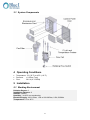
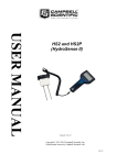
3.1 System Components
4 Operating Conditions
Temperature: 1ºC (35°F) to 45ºC (113°F)
Pressure:
< 0.5 Bar (7 psi)
Flow:
30 L/H (0.13 GPM)
5 Installation
5.1 Working Environment
Pollution Degree: 2
Installation Category: 2
Altitude: 2,000 m
Humidity: 1 to 90% non-condensing
Electrical Supply: 100-115Vac, 1.0A or 200-230Vac, 0.5A, 50/60Hz
Temperature: 5°C to 45°C
6
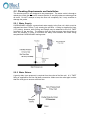
5.2 Plumbing Requirements and Installation
The chlorine probe is not designed to be pressurized. The water outlet is through a
raised pipe inside the flow cell to ensure that the Cl and pH probes are submerged at
all times. Do NOT attempt to keep the flow cell completely full; it may overflow or
damage the probe.
5.2.1 Water Supply
HYDROGUARD requires a pressurized water supply to the flow cell, which must be
adjusted less then 0.5 Bar (7 psi) entering the pre-filter. A fitting is supplied for 6mm
(1/4”) tubing; however other tubing and fittings may be attached to the 3/8” FNPT
connector on the pre-filter. The distance from the main process pipe should be as
short as possible, in order to minimize the delay time between the water being
sampled and HYDROGUARD testing water.
5.2.2 Water Return
A gravity drain (zero pressure) is required from the outlet of the flow cell. A ¼” FNPT
fitting is supplied for the flow cell drain connection. Make sure the outlet pipe is wider
than the inlet pipe to ensure sufficient flow.
7
5.3 Electrical Requirements and Installation
HYDROGUARD requires a 90-120 or 190-240 VAC, 50/60 Hz electrical power
source on a separate 16A circuit in the plant room’s electrical board. The main
HYDROGUARD power supply should be connected to a non-dependent power
supply, so that the unit remains powered constantly. Any relays used to directly
activate equipment should be powered by a dependent power supply (interlocked
power supply).
5.3.1 Connecting the Main Electrical Power
The Main Power Supply may be connected to either 90-120 or 190-240VAC
50/60Hz. Switching between voltages is accomplished by changing two (2) jumpers
located above the main power connection, to the left of the transformer.
For 90-120VAC, a 1amp fuse should be use
For 190-240VAC, a 0.5amp fuse should be used. These changes must be
completed prior to wiring.
CAUTION
Before making a connection to a power source, confirm that both jumpers are located
on the correct voltage and that the appropriate fuse is in place.
1. Verify that the power switch or circuit breaker to the non-dependent power source
is off.
2. Connect the line (live) wire to the I/O board connector marked Line.
3. Connect the neutral wire to the I/O board connector marked Neutral.
4. Connect the earth wire to the I/O Module connector marked Ground.
5. Continue with the other electrical connections.
6. Turn on electrical power only after all electrical connections have been
completed.
8
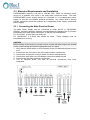
5.3.2 Input Switches
Flow input switch terminal blocks on the I/O module allow for three input switches to
be connected to the system as additional layers of security against accidental
chemical additions when there is no flow. If a connection is expected but not
detected at each input, the analyzer/controller will indicate an alarm and will open all
relays (and close the alarm relay). Therefore, if a safety switch (flow, level, etc.) will
not be installed, a fixed connection (jumper wire) is required to allow the controller to
operate.
Two flow switches and one flow meter may be connected:
Flow Switch (internal): Flow switch connected to flow cell of analyzer. Supports
both 2 and 3 wire flow switches.
o If a 2 wire switch is used, it should be connected to the “In” and “GND”
connections. If a 3 wire switch is used, the “VCC” connection will also be
used.
External Flow Switch ("external off"): Connection for external 2-wire flow switch.
If an external switch is not connected, a jumper must be installed for the analyzer
to operate properly.
Flow Meter: Connection for 2 or 3 wire flow Meter. The analyzer will not look for
the flow meter connection unless the option is turned ON in technician menu;
therefore, no jumper is required if a meter is not installed.
o White = VCC
o Green = IN
o Brown = Ground
CAUTION
Electrical connections in this section are ONLY recommendations. All electrical
connections should comply with National Electrical code (NEC) and all local
regulations.
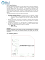
5.4 Installing Probes
9
NOTE
pH, and Cl Probes MUST be kept wet at all times. Fill the flow cell with water up to
the outlet drain pipe before installing probes.
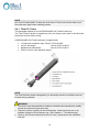
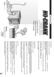
5.4.1 Total CL Probe
This paragraph applies for the HYDROGUARD HG-TotalCl model only.
The Total Chlorine probe is supplied dry from the factory and needs to be filled with
electrolyte solution before using.
HYDROGUARD HG-TotalCl analyzer is supplied with
1 Probe with membrane cap Cat No: 970-210-0303
100 mL electrolyte
Cat No: 970-210-8012
Replacement Membrane
Cat No: 970-210-8011
Piece of emery cloth (abrasive paper)
NOTE
The Total Chlorine probe is shipped dry (no electrolyte solution pre-filled) and must
be filled before operation
WARNING
The sensor must be assembled, installed, maintained and operated by suitably
trained and authorized personnel only.
Check the sensor regularly for dirt and deposits. Check that there are no air
bubbles clinging to the membrane cap. (See Chapter 8. “Troubleshooting”).
Observe the relevant national directives for care, maintenance and calibration
intervals.
10
Setup and mounting instructions
1. Unscrew the membrane cap from the chlorine electrode
2. Lift the hose ring on the membrane to expose the vent
3. Fill the electrode to the top with the supplied electrolyte solution
4. Screw the membrane cap onto the electrode
CAUTION
Excess electrolyte solution will escape through the vent and may spray. Do not
cover this vent and use caution and proper protective equipment as the electrolyte
solution contains dilute acid
5. Make sure the membrane cap is completely screwed in place. There will be
resistance at the O-ring but continue until the stop. The membrane should have
a slight curve if fully attached.
6. Replace the hose ring so that the vent is closed
7. Fill the flow cell with water and install the probe through the opening at the top.
8. Calibrate the probe after operating for at least 1 hour.
NOTE
The probe will require a second calibration after operating for 24 hours to allow for
complete polarization of the probe. Never “top-off” electrolyte solution.
Always empty the old solution before adding new electrolyte solution.
9. Install the probe into one of the open ½” openings on the top of the flow cell and
HAND-Tighten.
10. Connect the cable from the electronics enclosure to the top of the chlorine probe.
NOTE
Please read the complete operation instructions supplied with the probe.
5.4.2 pH Probe
Setup and mounting instructions
1. Install the probe into either ½” opening on the top of the flow cell and HAND-tighten.
2. Route the wire through an open hole in the gasket and connect to the
pH/Amp/Temp electronics card
a. Connect the center wire to the pH (+) terminal block
b. Connect the clamp onto the outside of the wire being sure that wire mesh
is in contact with the metal plate on the electronics card.
c. The pH (-) terminal block will remain empty
3. Connect the wire to the probe
a. Press the connector onto the top of the probe and hand tighten
5.4.3 Temperature Probe
Setup and mounting instructions
1. Install the probe into the compression fitting opening on the top of the flow cell
and HAND-Tighten the fitting.
2. Route the wire through an open hole in the gasket and connect to the bottom of
the pH/Amp/Temp electronics card
a. Connect the Black wire to the connection labeled black
b. Connect the White or Yellow Wire to the connection labeled Yellow
c. Connect the red wires to the connection labeled red*
*either red wire may go to either connection
11
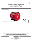
5.4.4 Probe cables and Electronics Card
The Cl probe cable is pre-wired on the electronics card from the factory. The wiring
diagram is for information only; no additional wiring is required.
6 First Time Operation
6.1 Menus and Settings
HYDROGUARD HG-TotalCl has two menu levels: Operator and Technician. The
Operator menu includes settings that may be controlled by on-site operators. The
Technician menu includes settings and calibrations that should be restricted to
specially trained HydroGuard maintenance technicians. Each menu has a separate
password. The technician level password may be used whenever a password is
required, however the operator password will only be accepted in the operator menu.
NOTE
The default Operator Password is: 123
The default Technician Password is: 456.
Caution
DO NOT Forget your password!
There is no way to reset the technician password without a complete reprogramming
of the HYDROGUARD System.
12
Each of the parameters in the operator menu is configured in the same way. The
following procedure describes how to configure a typical setting:
1. Locate the desired parameter in the menu:
a. Press Menu until the desired parameter name appears in the LCD display.
2. Press OK. Enter Password 100 appears in the LCD display.
3. Enter the Operator password (or technician password; both are accepted)
4. Press the up arrow or down arrow until the password number is reached.
Holding Menu while pressing up or down will advance the first digit. Holding up
or down for an extended period of time will proceed through the numbers more
quickly.
5. Press OK to accept the password. The parameter name and current setting
appear in the LCD display.
6. Press OK, again. The LCD display shows the parameter and the current setting.
7. Enter the new parameter setting:
a. Press the up arrow or down arrow until the desired value is reached.
b. The second row of the menu display, below the value that is being changed,
shows the current value.
8. Press OK to save the new setting or Esc to abort without saving the new setting.
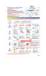
To change the settings of additional parameters,
press Menu until the desired parameter appears
in the LCD display and repeat steps 6-8 above to
set the new parameter. The table on the right
outlines an example of menu settings.
6.2 Entering the Technician Menu
1. Press Menu to enter the operator menu then press UP + DOWN together until the
display changes to menu # 51.
2. Navigate the menus exactly the same as the operator menus, but the technician
password is the only password accepted.
13
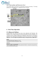
6.3 Configuring Internal 4-20mA Outputs
The menu for internal 4-20mA settings is found in the technician menu.
1. Set the 4-20mA outputs
a. Enter the technician menu and scroll until “4-20 Settings” appears in the LCD
b. Enter the technician password and press OK.
c. Select the Output Channel (1 or 2 on-board or 1 to 4 on NTU/4-20 card)
d. Select the output Parameter (T-Cl, pH, etc.)
e. Select the Min Value (value = 4mA output)
f. Select the Max Value (value = 20mA output)
g. Test the output (with multi-meter set on mA)using the test output settings will
help adjusting the external unit (PLC)
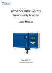
Repeat the above steps for the remaining
outputs. The table on the right outlines some
example settings. Note that a single variable
may be the output of more than one channel.
2. Set the 4-20mA alarm output
a. 2mA, 4mA, 20mA, or hold last value
The 4-20 alarm output is the output value that will be sent in case of an
insufficient flow problem to the HYDROGUARD. In case of low or high level (i.e.
low chlorine), no 4-20mA alarm will be activated.
7 Calibration
Parameters must be calibrated with measurements taken with external testing
devices or standard (buffer) solutions. Always use digital calibration devices, not the
less accurate visual test kits. Alternatively, standard solutions may be used. Make
sure the standard solution is not expired or contaminated prior to using. Follow the
procedures below EXACTLY as instructed
NOTE
ALWAYS take water for calibration from the sampling valve and NOT from the
process line directly. The analyzer should always be calibrated with water from the
same source.
NOTE
Because of the strong influence of pH on chlorine, it is highly recommended to
include pH with every analyzer. If pH is not an installed parameter, an accurate pH
value must be set in the calibration menu.
7.1.1 Calibrating Temperature
Calibration of temperature requires an accurate external thermometer.
1. Place the external thermometer in the flow cell or place both the PT-100 and
thermometer in the same sample.
2. Wait for both temperature readings to stabilize.
3. Press Menu until “Temp Calibrated to” appears in the LCD display.
4. Press OK.
14
5. Enter the password. Press the up arrow or down arrow until the password is
reached.
6. Press OK.
7. Press OK again.
8. Press the up arrow or down arrow until the value is the same as the thermometer.
9. Press OK to save the new calibration or Esc to abort without saving.
10. Press Esc to return to the main display.
7.1.2 Calibrating pH
Calibration of pH is similar to the chlorine calibration and requires the use of a
reliable external testing device or standard solution. When using an external testing
device, follow the Chlorine calibration sequence making sure to take the sample
water from the same supply to that probe or sensor.
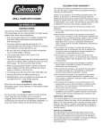
Using Standard Solutions
1. Remove the pH and temperature probes,
and clean with a dry cloth.
2. Place the probes in the standard solution and
wait for the reading to stabilize.
NOTE
1. For pH calibration, the temperature probe
must also be placed in the standard
solution for the reading to stabilize.
2. pH is calibrated using 2 points
3. Press Menu until “pH 7 Calibrated to”
appears in the LCD display.
4. Press OK.
5. Enter the password. Press the up arrow or down arrow until the password is
reached.
6. Press OK.
7. Press OK again.
8. Press the up arrow or down arrow until the value is the same as the standard
solution.
9. Press OK to save the new calibration or Esc to abort without saving.
10. Press Menu until “pH 4,10 Calibrated to” appears in the LCD display.
11. Press OK.
12. Enter the password. Press the up arrow or down arrow until the password is
reached.
13. Press OK.
14. Press OK again.
15. Press the up arrow or down arrow until the value is the same as the standard
solution.
16. Press OK to save the new calibration or Esc to abort without saving.
17. Press Esc to return to the main display.
15
7.1.3 Chlorine Calibration (Using External Test)
Before calibrating Chlorine, calibrate both temperature and pH and insure that both
temperature and pH are at normal operating levels.
This method is also valid for other variable calibration using external testing devices.
1. Fill the sampling container from the HYDROGUARD flow cell.
2. Test the water sample for chlorine using a digital photometer or other external
testing device.
3. Press Menu until “Cl Calibrated to” appears in the LCD display.
The top line will display “Cl Calibrated to” and a number. The number displayed
is the last value someone entered for the calibration. The bottom line will display
“Cl Sensor was” and a number. This number is the sensor reading without any
calibration at the time of the last calibration. If there is a large discrepancy
between these two numbers, the sensor was calibrated improperly or there is a
problem with the analyzer. The value displayed normally on the main screen and
the value the analyzer uses to determine dosing rates is the calibrated value.
NOTE
Chlorine calibration should always be performed within 25% of the set point. If
current chlorine level is 25% above or below the set point, do not perform
calibration until the chlorine level is closer to the set point.
4. Press OK.
5. Enter the password. Press the up arrow or down arrow until the password is
reached.
6. Press OK.
7. Press OK again.
The display will now show “Calibrate Cl to” on the top line and “Sensor Reading” on
the bottom line. The “Sensor Reading” is the current reading of the sensor with no
calibration. The “Calibrate Cl to” value is the new value which you want to set.
Press the up arrow or down arrow until the value is the same as the value given by
the digital photometer.
Press OK to save the new calibration or Esc to abort without saving.
Press Esc to return to the main display.
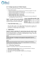
8 Maintenance
8.1 Cleaning the Filter
This filter must be cleaned regularly as it becomes clogged with debris and
impurities. The frequency at which the filter requires cleaning depends entirely on
how much debris is in the water. Clean the filter whenever a visible layer of dirt has
accumulated on the filter using only water.
8.2 Shut-Down and Winterizing
The HYDROGUARD analyzer is designed to keep the probes submerged even if
there is no flow to the analyzer. However, if the analyzer is going to be offline for an
extended period of time and/or exposed to freezing temperatures, it must be
winterized to prevent damage to the analyzer and the probes.
16
1. Store all probes following directions in the supplemental manuals for each
sensor.
a. Cl, pH sensors MUST be stored in water at all times.
2. Drain the flow cell completely by opening the sampling valve on the bottom.
Leave the valve in the open position to allow air to completely dry the cell.
3. Check the security of the analyzer doors to ensure a weatherproof seal.
8.3 Start-up and Preventive Maintenance
1. Replace all additional sensors and meters, close the sampling valve and turn on
flow immediately to re-wet any probes.
2. Recalibrate the analyzer.
NOTE
Cl probe may take as long as 90-120 minutes to re-polarize and will need to be
recalibrated at that time.
pH probe will likely require 24-48 hours to re-stabilize and will require re-calibration at
this time.
8.4 Cl Probe Maintenance
8.4.1 Cleaning the Filter
This filter must be cleaned regularly as it becomes clogged with debris and
impurities. The frequency at which the filter requires cleaning depends entirely on
how much debris is in the water. Clean the filter whenever a visible layer of dirt has
accumulated on the filter using only water.
8.4.2 Cl Probe Maintenance
If the membrane is visibly soiled, clean the sensor
Refill the sensor with electrolyte once per season or every 12 months. Depending
on
the water quality and chlorine level, this period can be reduced or extended
Calibrate the sensor when necessary (see "Calibration").
8.4.3 Cleaning the sensor
CAUTION
Do not use chemicals reducing the surface tension. When using hydrochloric acid,
observe the safety regulations.
1. Remove the sensor from the flow assembly.
2. Clean the membrane mechanically with a gentle water jet or swirl in a solution of
2% hydrochloric acid (no other additives).
3. If the membrane is still visibly soiled, replace the membrane.
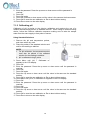
8.4.4 Replacing the membrane
1.
2.
3.
4.
Unscrew the measuring chamber from the shaft.
Unscrew the front screw cap holding the membrane
Remove the membrane and replace with a new membrane.
Refill the measuring chamber with electrolyte
17
8.4.5 Refilling the electrolyte
WARNING
Do not swallow the electrolyte. Avoid contact of the electrolyte with skin or eyes. In
case of accidental contact wash with a lot of cold water! In case of eye inflammation,
contact a doctor immediately. Wear safety glasses and gloves when working with the
electrolyte solution.
CAUTION
Do not touch or damage the electrodes. The electrolyte is sensitive to oxidation:
Always keep the electrolyte bottle closed after use. Do not transfer the electrolyte into
other containers. The electrolyte should not be stored for more than 1 year and not
yellow (use by date, see label). Avoid forming air bubbles when pouring the
electrolyte into the measuring chamber
1. Unscrew the measuring chamber from the sensor shaft.
2. Hold the measuring chamber at an angle and fill in about 7 to 8 ml (0.24 to 0.27
fl.oz) electrolyte, up to the internal thread of the measuring chamber.
3. Tap the filled measuring chamber several times on a flat surface so that air
bubbles can detach and rise.
4. Insert the sensor shaft vertically from above into the measuring chamber.
5. Slowly tighten the measuring chamber to the stop. Excess electrolyte is pressed
out at the sensor during the tightening.
8.4.6 Reconditioning the sensor
Long-term operation (> 1 week) in chlorine-free media, i.e. with very low sensor
currents, leads to a deactivation of the sensor. This deactivation is a continuous
process that results in a lower slope and longer response times.
After long-term operation in a chlorine-free medium, the sensor must be
reconditioned.
The following materials are required for reconditioning:
Demineralized water (or electrolyte)
Polishing sheet (Emory Cloth -- see Accessories)
Beaker
Approx. 100 ml (3.4 fl.oz) of chlorine bleach liquor NaOCl approx. 13%,
pharmaceutical quality (available at chemical stores or pharmacies)
1. Remove the sensor from the assembly.
2. Unscrew the measuring chamber and set it aside.
3. Polish the gold cathode of the sensor using the polishing sheet:
– Place a wetted strip of the sheet in your hand.
– Polish the gold cathode by moving it circularly on the strip.
– Rinse the sensor with demineralized water (or electrolyte).
4. Top up the electrolyte if required and screw the measuring chamber back into
place.
5. Fill the beaker with chlorine bleach liquor to about 10 mm (0.39") and position it
safely.
CAUTION
The sensor must not touch the liquid. Place the sensor in the gaseous phase about 5
to 10 mm (0.2" to 0.39") above the chlorine bleach liquor.
18
6. The sensor current will now increase. The absolute value and the speed of
increase depend on the temperature of the chlorine bleach liquor.
– When the sensor has reached a high value CL reading, leave the sensor
under these conditions over a period of 20 min.
– If the chlorine value is not increasing, cover the beaker to minimize air
movement.
7. After the 20 min. have elapsed, re-install the sensor in the assembly.
8. Re-establish flow. The sensor current will normalize.
9. After sufficient settling time (no noticeable drift), calibrate the probe.
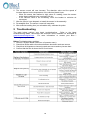
9 Troubleshooting
The table below outlines very basic troubleshooting.
Refer to the latest
troubleshooting tables, documents and technical notes, available for download at
www.blueitechnologies.com.
For more information or contact your Blue I
Technologies’ representative.
Before Troubleshooting a problem:
1. Perform a System Reset (last menu of operator menu)
2. Check that all flat cable connections between electronic cards are secure
3. Check that all chipsets on electronic cards are secure and no pins are bent
4. Confirm that the flow is above the 30 l/h minimum.
19
No part of this publication may be reproduced, transmitted, transcribed, stored
in a retrieval system, or translated into any language or any computer
language, in any form or by any third party, without the prior written
permission of Blue I Water Technologies Ltd.
Trademarks and Patents
HYDROGUARD is the Registered trademark of Blue I Water Technologies Ltd.
Patents issued at the time of this printing
Disclaimer
Blue I Water Technologies Ltd. does not accept any responsibility for any
damage caused to its products by unauthorized personnel. Use of non-Blue I
Water Technologies’ reagents and/or replacement parts will void all warranties.
Blue I Water Technologies Ltd.
www.blueitechnologies.com
2218 Ha'melacha St., Rosh Ha'ayin 4809148, Israel ǀ Tel: 972-9-7680004 ǀ Fax 972-9-7652331
20