1
Polycom® RSS™ 4000 System
User Guide
7.0.0 | Oct. 2011 | 3725-32870-002/C
Trademark Information
Polycom®, the Polycom “Triangles” logo, and the names and marks associated with Polycom’s products are
trademarks and/or service marks of Polycom, Inc., and are registered and/or common-law marks in the United
States and various other countries.
All other trademarks are the property of their respective owners.
Patent Information
The accompanying product is protected by one or more U.S. and foreign patents and/or pending patent
applications held by Polycom, Inc.
© 2011 Polycom, Inc. All rights reserved.
Polycom, Inc.
4750 Willow Road
Pleasanton, CA 94588-2708
USA
No part of this document may be reproduced or transmitted in any form or by any means, electronic or
mechanical, for any purpose, without the express written permission of Polycom, Inc. Under the law,
reproducing includes translating into another language or format.
As between the parties, Polycom, Inc., retains title to and ownership of all proprietary rights with respect to the
software contained within its products. The software is protected by United States copyright laws and
international treaty provision. Therefore, you must treat the software like any other copyrighted material (e.g.,
a book or sound recording).
Every effort has been made to ensure that the information in this manual is accurate. Polycom, Inc., is not
responsible for printing or clerical errors. Information in this document is subject to change without notice.
Contents
Polycom® RSS™ 4000 Introduction ················································· 1-1
Overview ········································································ 1-1
System Hardware Installation ·············································· 1-2
General Safety Precautions ·············································· 1-2
Unpack the Package······················································· 1-2
Install the System ·························································· 1-3
System Indicators ·························································· 1-3
System Initial Configuration ················································ 1-4
Preparations before Configuration ···································· 1-4
Modifying the Initial IP Address ······································ 1-5
(Optional) Installing Multicast Controls ····························· 1-8
(Optional) Configuring the Gatekeeper Settings ·················· 1-8
User Interface ··································································· 1-9
Web User Interface ························································ 1-9
TV User Interface ·························································· 1-9
Working Mode ································································ 1-10
Basic Operations············································································· 2-1
Introduction to the Web User Interface ·································· 2-1
User Permissions··························································· 2-2
Common Operations······················································ 2-2
Starting a Recording ·························································· 2-3
Playing Back Recorded Files ················································ 2-5
Ordinary User Configuration ··························································· 3-1
Personal Settings ······························································· 3-1
Virtual Recording Room (VRR) ············································ 3-2
Dialing-in to a VRR to Start Recording······························· 3-2
Modifying a VRR ·························································· 3-3
Archives ·········································································· 3-5
Viewing Archives ·························································· 3-5
Playing Back and Downloading Archives··························· 3-5
Modifying Archives ······················································· 3-7
Quick Code ······································································ 3-8
Polycom, Inc.
i
Polycom® RSS™ 4000 User Guide
Live Streaming ································································· 3-9
Starting a Live Streaming ················································ 3-9
Viewing Live Streaming Information ································ 3-9
Viewing Live Streaming Video········································· 3-9
Multicast ········································································ 3-10
Multicast of an Archive or a Live Streaming Video ·············· 3-10
Viewing Multicast Video ··············································· 3-11
Administrator Configuration ···························································· 4-1
Recording Templates ························································· 4-1
Viewing Template Information ········································ 4-1
Defining a Template ······················································ 4-1
Managing Templates ····················································· 4-4
Virtual Recording Room (VRR) ············································ 4-4
Defining a VRR ····························································· 4-4
Dialing-into a VRR to Start Recording ······························· 4-7
Managing VRRs ···························································· 4-7
Multipoint Recording ························································· 4-8
Multipoint Recording and Live streaming Resource Usage ···· 4-8
Creating a Multipoint Recording Room ····························· 4-9
Reservation VRR ······························································ 4-10
Creating a Reservation VRR ··········································· 4-10
Channel·········································································· 4-11
Recording Setting ····························································· 4-12
Archives ········································································· 4-13
Re-transcoding Archives ················································ 4-13
Live Streaming ································································ 4-13
Live Streaming Resources Usage ····································· 4-13
Multicast ········································································ 4-15
Configuring Multicast ··················································· 4-16
Multicast Operation ······················································ 4-16
Network Service ······························································ 4-16
IP Setting ···································································· 4-16
Gatekeeper ································································· 4-18
SIP ············································································ 4-19
QoS ··········································································· 4-20
User Management ···························································· 4-21
ii
Polycom, Inc.
Polycom® RSS™ 4000 User Guide
User ·········································································· 4-21
Viewing Users ····························································· 4-22
Adding a New User ······················································ 4-24
Managing Users ··························································· 4-25
Groups······································································· 4-25
Creating a New Group ·················································· 4-26
Managing Groups ························································ 4-26
Service Setting ································································· 4-26
Active Directory··························································· 4-26
Calendar Configuration ················································· 4-27
System Monitoring ··························································· 4-29
Dashboard ·································································· 4-29
Auditor ······································································ 4-32
Log Setting ································································· 4-33
Hard Disk Warning ······················································ 4-33
System Security ······························································· 4-34
Ports ·········································································· 4-34
Ping··········································································· 4-34
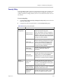
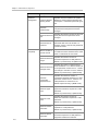
Security Policy ····························································· 4-35
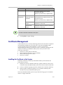
Certificate Management····················································· 4-37
Installing the Certificate in the System ······························ 4-37
Viewing the Certificate Details ········································ 4-40
Removing a Certificate ·················································· 4-40
Using OCSP to Obtain Revocation Status ·························· 4-40
Enabling the Client Certificate Validation·························· 4-41
Maximum Security Mode··················································· 4-41
Running the System in Maximum Security Mode ··············· 4-42
Antivirus Protection ····················································· 4-43
System Management ························································· 4-45
System Configuration Backup/Restore ····························· 4-45
Data Backup/Restore ···················································· 4-45
System Upgrade ·························································· 4-48
Product Activation ······················································· 4-51
UI Customization ························································· 4-52
System time ································································ 4-54
Restart and Shutdown ··················································· 4-55
Polycom, Inc.
iii
Polycom® RSS™ 4000 User Guide
Restoring Factory Default Configuration ··························· 4-55
System Recovery ·························································· 4-56
TV User Interface Operation ···························································· 5-1
Introduction to Main Menu Page ·········································· 5-1
Start Recording ································································· 5-3
Viewing Archives ······························································ 5-4
Appendix A – Telnet/Terminal Commands ········································ 6-1
HyperTerminal Parameters ················································· 6-1
Login ·············································································· 6-1
Command Introduction ······················································ 6-2
Appendix B – Regulatory Notices ···················································· 7-1
iv
Polycom, Inc.
1
Polycom® RSS™ 4000
Introduction
Overview
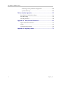
The Polycom® RSS™ 4000 Recording and Streaming Server is a web server
that enables you to easily perform recording, live streaming, stream media
processing and multimedia archiving. Polycom® RSS™ 4000 system
supports the recording of single-point, multipoint, and multipoint video
conferences, including H.239 data contents. It can record and archive up to
1080P and live stream to the network audience at a quality of up to 720P.
The Polycom® RSS™ 4000 provides the following features:
Polycom, Inc.
•
Supports recording of up to 15 concurrent video conferences, as well as
full video, audio and content recording.
•
Supports resolutions of up to 1920 x 1080 (1080p) and 4Mbps of
bandwidth for recording.
•
Supports H.264 High Profile for delivering greater definition and higher
clarity video with lower bandwidth than the baseline profile.
•
Supports video conference live streaming, using Windows Media, which
can use two different bandwidths.
•
Supports the multicast of recorded or live streaming events, with up to
20 simultaneous multicast sessions.
•
Uses a Virtual Recording Room (VRR) as a base for recording and
authorizing playback permission. Users can have their own VRR for
recording and playing back.
•
Offers various recording methods. Users can start a recording from
endpoints, an MCU or the Web user interface.
•
Supports the integration with Polycom HD Series endpoints and
Polycom RMX/MGC conference platform to manually and
automatically perform recording, live streaming and playback.
•
Supports the integration with Polycom Video Media Center™ (VMC)
1000 V2.0 for more powerful stream media management.
•
Supports integration with Exchange server, and works with other
Polycom video conferencing devices for recording or live streaming
conferences when scheduling conferences through Outlook.
•
Offers recorded archives in multiple video formats, so that users can
view content through an endpoint, the Web user interface and
MP4-supported players like an iPhone and an iPod.
1-1
Chapter 1 - Polycom® RSS™ 4000 Introduction
•
Supports the recordings of audio-only and conversion to MP3 files for
downloading and playing.
•
Supports the maximum security mode (MSM) for meeting high-security
environment requirements.
•
Supports SSL certificate authentication encryption to ensure the data
security of Web communication.
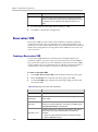
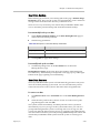
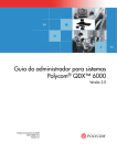
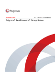
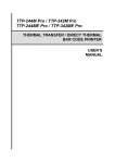
Figure 1-1 Polycom® RSS™ 4000's Application in the Video Conference Network
System Hardware Installation
General Safety Precautions
Follow these rules to ensure general safety:
•
Keep the area around the Polycom® RSS™ 4000 unit clean, free of
clutter and well ventilated.
•
Decide on a suitable location for the equipment rack that will hold the
Polycom® RSS™ 4000 unit and is near a grounded power outlet.
•
Use a regulating uninterruptible power supply (UPS) to protect the
Polycom® RSS™ 4000 unit from power surges and voltage spikes, and
to keep it operating in case of a power failure.
Unpack the Package
To unpack the system package:
1
Check the package to ensure its completion.
2
Open the package and check the items included. The following items
should be included:
― One Polycom® RSS™ 4000 server unit
― Two power cables
― Two RJ-45 network cables
1-2
Polycom, Inc.
Chapter 1 - Polycom® RSS™ 4000 Introduction
― One DB9 serial port cable
― A CD
― A license and a user registration card
Take all items out of the package and check if any of them is in poor
condition.
3
If you find damage, file a claim with the delivery carrier. Polycom is not responsible for
damage sustained during shipment of this product.
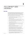
Install the System
1
Place the Polycom® RSS™ 4000 unit on a stable flat surface in the
selected location.
2
Insert each power cord connector into the rear of the unit and connect
each to an appropriately rated socket outlet.
The Polycom® RSS™ 4000 unit is supplied with two power cords, BOTH
power cords should be connected to the mains power supply during
normal operation.
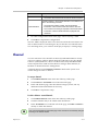
3
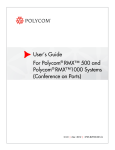
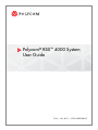
Connect the LAN cable to LAN1 in the back of the system.
The LAN2 port is used when the system runs in the maximum security
mode. For more information, refer to Maximum Security Mode.
4
Turn on the power switch.
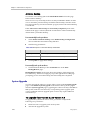
Figure 1-2 Connecting Cables
Plug Acts as Disconnect Device:
The socket outlets to which this apparatus is connected must be installed near
the equipment and must always be readily accessible.
In order to fully isolate the equipment then both power cords should be
disconnected otherwise the system will remain energized.
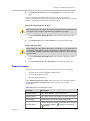
System Indicators
When the system is running, indicators on the front panel indicate operating
conditions of the system. Refer to the table below for the indicators and their
explanations.
Polycom, Inc.
1-3
Chapter 1 - Polycom® RSS™ 4000 Introduction
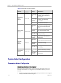
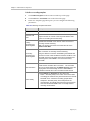
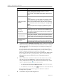
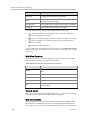
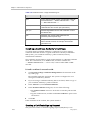
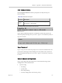
Table 1-1 Explanation of System Indicators
Indicator
LAN1 Activity
Status
Indicator
System Status
Indicator
Hard Disk
Status
Indicator
Power Status
Indicator
Panel
Identifier
LAN1 LED
STATUS LED
HDD LED
Status
Explanation
Green light
on
Network port is functioning
normally, with no data being
transmitted
Green light
blinking
Network port is functioning
normally, with data being
transmitted
Off
No Network connection
Blue light
on
System is functioning normally,
with no resources being used
(idle)
Blue light
blinking
System is functioning normally,
with resources being used
Red light on
System alert, with no resources
being used (idle)
Red light
blinking
System alert, with resources
being used
Blue light
on
Hard disk is functioning normally
Blue light
blinking
System is recording
Red light on
Hard disk is functioning
abnormally
Green light
on
Power is functioning normally
Red light
blinking
Power alert
Power LED
System Initial Configuration
Preparations before Configuration
Obtaining Network Information
Before the initial configuration, get the following information from your
network administrator to configure Polycom® RSS™ 4000 to your local
network:
•
1-4
IP address, subnet mask, and default gateway IP address to be assigned
to Polycom® RSS™ 4000 LAN ports.
Polycom, Inc.
Chapter 1 - Polycom® RSS™ 4000 Introduction
•
(Optional) Your DNS server address. The Polycom® RSS™ 4000 is
shipped with the default DNS server addresses 208.67.222.222 and
208.67.220.220 pre-configured.
•
(Optional) Gatekeeper address, and the H.323 prefix and E.164 number
to be assigned to the Polycom® RSS™ 4000.
Obtaining the Product Activation Key
Before using Polycom® RSS™ 4000, you need to activate the device. Follow
the procedure below to obtain the product activation key. When you power
on and log in to the Polycom® RSS™ 4000 for the first time, the system
displays the product activation page, prompting you to enter a product
activation key.
1
Enter the following website address in the address bar of the browser:
http://support.polycom.com, and go to the Polycom Support Center.
2
Enter your Email address and password to log in or register for a new
account.
3
Go to Licensing & Product Registration > Activation/Upgrade.
4
Follow the page prompts step by step to generate the Key Code required
for system activation.
If you are required to enter the License Number and Serial Number of
the device, you can find them from the document provided with the
Polycom® RSS™ 4000 device.
5
Record the activation key (Key Code) on the page.
Modifying the Initial IP Address
The system default IP address of LAN 1 port before delivery is:
IP Address: 192.168.1.254
Subnet Mask: 255.255.255.0
Gateway: 192.168.1.1
There are two ways to change the initial LAN 1 IP address:
•
Via Web login page (recommended)
•
Via Console or Telnet connection
To change IP address via the Web interface:
Polycom, Inc.
1
Connect your computer to the LAN 1 port of the Polycom® RSS™ 4000
with a cross-over network cable, or connect your computer and
Polycom® RSS™ 4000 to the same switch in the LAN.
2
Set your computer IP address to be in the same network segment as the
Polycom® RSS™ 4000.
3
Run the Web browser on your computer, enter https://<system IP
address> in the address bar, and then press Enter.
1-5
Chapter 1 - Polycom® RSS™ 4000 Introduction
By default, Polycom® RSS™ 4000 Web server has an untrusted certificate and
uses the HTTPS protocol to set up SSL secure connection with client end.
If you use Internet Explorer as a browser, you will be prompted that the security
certificate for the website has some problem. Please choose Continue to this
website to enter the Login page.
If you use Firefox browser, you will be prompted that the connection is not
trusted. Please add the site being connected to Security Exception as suggested
on the page and enter the Login page.
After you install the security certificate issued by the Certification Authority in
your system, you will not receive this alert again. Refer to Error! Reference
source not found..
4
(Optional) Select a language for the Web interface from the Select
language list in the top right of the page.
5
On the Login page, enter the administrator’s username and password,
and then click the Log In button. The default username and password
are both admin.
6
The Product Activation page displays when you first-time log in. Enter
the activation key obtained from the previous step Obtaining the Product
Activation Key in the Activation Key box and click Update.
If you do not activate the system, you can still use the Web interface, but cannot
perform incoming calling, recording, live streaming, and video playing operations
using the system.
7
When prompted to restart the system, select No to proceed with setting
the IP address.
8
Click System Config > IP Setting and configure the following
parameters in the Network Setting area.
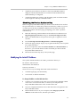
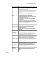
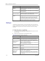
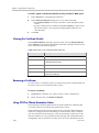
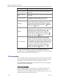
Table 1-2 Signaling Network Parameters Description
1-6
Parameter
Description
Obtain an IP Address
Automatically (DHCP)
Specifies the system to obtain an IPv4 automatically.
Using the following IP
Address
Specifies whether to use a static IPv4 address. You need to
manually enter the IP address and subnet mask.
Enable IPv6
Specifies whether to enable IPv6 related functions.
Obtain an IP Address
Automatically (IPv6)
Specifies whether to obtain the IPv6 address automatically
using Stateless Address Auto-configuration (SLAAC).
Using the following IP
Address (IPv6)
Selects this option to manually configure a static IPv6
address. You need to enter the link local address, site local
address and global address.
Enable ICMP V6 DAD
Specifies whether to enable the Duplicate Address
Detection (DAD) to ensure the IPv6 address set to the
system is unique in the local network.
Note: Obtaining an IP Address Automatically is not
recommended. For best results, the system should be
configured with a static IP address.
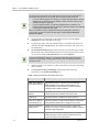
Polycom, Inc.
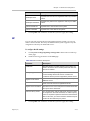
Chapter 1 - Polycom® RSS™ 4000 Introduction
Parameter
Description
Enable ICMP Echo
Specifies whether to enable the system to respond to an
ICMP echo request (Ping) sent from other devices in the
network. In some high-security environments, you may
need to disable this option to protect the system from Ping
attacks.
LAN Speed
Specifies the speed/duplex modes for LAN port. Supports
the 10/100M Full Duplex or Half Duplex mode and the
1000M network. Select Auto to use auto-negotiation.
Note: When setting LAN port speed, contact your network
administrator to ensure that the switch link rate matches
the system port speed.
9
In the General System Network Settings area, configure the following
settings.
Table 1-3 General System Network Parameters Description
Parameter
Description
Enable Destination
Unreachable Message
Specifies whether to enable the system to forward ICMP
destination unreachable messages that come from other
network devices when the system is configured to serve as
a router.
Host Name
Specifies the host name of the system.
Domain
Specifies the domain name of the system.
Gateway
Specifies the address of the interface to use for accessing
the IPv4 gateway.
Default IPv6 Gateway
Specifies the address of the interface to use for accessing
the IPv6 gateway.
Preferred/Alternate
DNS Server Address
Specifies the preferred or alternate DNS server addresses
here for the system to resolve domain names.
NAT Public (WAN)
Address
Specifies whether to enable the Network Address
Translation (NAT). Network Address Translation
environments use private internal IP addresses for devices
within the network, while using one external IP address to
allow devices on the LAN to communicate with other
devices outside the LAN.
Enter the external IP address here if this option is enabled.
10
Click Update and confirm to restart the system to apply the setting.
To change IP address via RS-232 Console or Telnet:
Polycom, Inc.
1
Connect your computer to the RS232 port of the Polycom® RSS™ 4000
with a serial port cable and activate the console port (115200, 8bits).
2
After you logged in to the console port, input the default password
POLYCOM to enter the system.
1-7
Chapter 1 - Polycom® RSS™ 4000 Introduction
3
Enter "?" or "help" after the prompt "#" and the system displays available
command information.
4
Change IP address using the command in the format below:
set lan1 ip {dhcp | static <ip> netmask <mask> gw <gateway>}
For example, to set the IP address of LAN1 port to 172.21.103.29, subnet
mask to 255.255.255.0 and gateway address to 172.21.103.254, enter the
following command:
5
After the system is restarted, activate the device according to Steps 3 to 6
described in the section To change IP address via the Web interface.
Points to note:
The same steps are also applicable for a Telnet connection.
Only one console (Telnet or RS232) at a time can be connected.
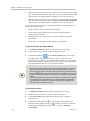
(Optional) Installing Multicast Controls
When you activate the device and subsequently connect to the system's web
management interface for the first time, you will be prompted that a
Polycom RSS 4000 multicast add-in is required at the top of the browser.
Make sure you use the Internet Explorer browser. If you have already
purchased the multicast license, please install the controls according to the
prompt on the screen. Only after this installation can your computer receive
multicast videos sent by Polycom® RSS™ 4000 system.
If you use an IE7.0 or IE8.0 browser, please first confirm the Security Mode
option (Tools->Internet Options->Security) is disabled before installing the
controls, to ensure successful installation and normal use of the multicast
function.
If you use the Windows 7 operation system, you must log in to the system as
an administrator to be able to install the controls.
(Optional) Configuring the Gatekeeper Settings
If a gatekeeper is configured on your network, register the Polycom® RSS™
4000 to the gatekeeper to simplify calling.
To register the system to the gatekeeper:
1-8
1
Click System Config > Signaling Setting > H.323 in the Web
configuration interface.
2
Set the following parameters in the gatekeeper page.
Polycom, Inc.
Chapter 1 - Polycom® RSS™ 4000 Introduction
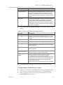
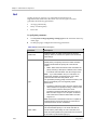
Table 1-4 Gatekeeper Parameters Description
Parameter
Description
Register to Gatekeeper
Indicates whether or not to register to the gatekeeper. You
must check this option to set the following parameters.
Primary (Alternate)
Gatekeeper
Indicates whether the system has been registered to the
primary (or alternate) gatekeeper.
Note: The alternate gatekeeper is used when the primary
gatekeeper is not available.
Gatekeeper IP Address
Specifies the IP address for the primary or alternate
gatekeeper.
Gatekeeper Port
Specifies the port number for the primary or alternate
gatekeeper.
Register’s User
Information to
Gatekeeper
Specifies whether to register the system to Polycom DMA
7000 for H.235 .0 authentication.
When H.235.0 authentication is enabled, the gatekeeper
ensures that only trusted endpoints are allowed to access
the gatekeeper.
Gatekeeper User
Specifies the user name for registration with the Polycom
DMA server.
Gatekeeper Password
Specifies the password for registration with the Polycom
DMA server.
System Prefix/E164.
Specifies the E.164 number for the system.
System H.323Alias
Specifies the H.323 alias for the system.
3
Click Update and confirm to restart the system to apply the setting.
User Interface
The Polycom® RSS™ 4000 provides two types of user interfaces: Web
configuration interface and endpoint TV user interface.
Web User Interface
The system provides a user-friendly Web-based operations interface. To
easily and conveniently configure recording parameters, record and play
back, monitor the system and maintain the device, you only need to access
the Polycom® RSS™ 4000 Web client program through a browser.
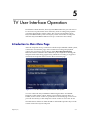
TV User Interface
TV user interface (TV UI) provides a menu-based onscreen interface
displayed on an endpoint. You can perform common recording and
playback operations with an endpoint's remote control and onscreen
operation menus.
Polycom, Inc.
1-9
Chapter 1 - Polycom® RSS™ 4000 Introduction
Working Mode
The Polycom® RSS™ 4000 can work in two types of mode: normal mode
and maximum security mode.
The normal mode provides the maximum access to the system
functionalities and is the most commonly used mode for general video
conferencing environments. Unless otherwise noted, the following chapters
introduce the system on the assumption that it runs in the normal mode.
The maximum security mode is intended for high-security environments by
disabling unsecure features and access interfaces, implementing enhanced
security protection policies, separating the network signaling and
management traffic, and limiting operations that may bring potential risks.
For more information, refer to Maximum Security Mode.
1-10
Polycom, Inc.
2
Basic Operations
Introduction to the Web User Interface
Run the Web browser on your computer. Enter https://<system IP address>
in the address bar and then press Enter to display Web login page of
Polycom ® RSS™ 4000 system. Enter your username and password to log in
to the system. Default administrator username and password are both
admin.
The Web UI basically consists of the following four parts:
•
Menu bar: Provides all the function groups for system configuration.
You can navigate to specific function configuration pages through these
menu items.
•
Group of page controls: Enables you to perform controlling operations
on a Web page:
―
―
―
Polycom, Inc.
: Displays information about the logged-on user and sets the
displayed font size for the Web page.
: Enables you to exit the Web configuration page.
: Locks the Web configuration page. When you click this button,
the system's web page is locked. You need to enter the password to
unlock it before viewing and performing operations on it.
•
Navigation/Operation bar: Provides navigation links to a group of
related function pages, for which some available operation items may be
shown.
•
Lists/Configuration area: Shows item lists, detailed parameters, or
configuration items.
2-1
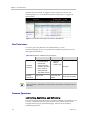
Chapter 2 - Basic Operations
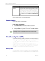
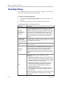
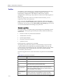
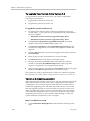
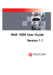
The Web UI varies based on logged-on users' permission levels. The
following figure is a screenshot of the Web UI displayed to a logged-on
administrator.
Menu bar
Group of page controls
Navigation/
operation
bar
Lists/Configuration area
Figure 2-1 Screenshot of the Polycom ® RSS™ 4000 Web UI
User Permissions
You can log in to the Web UI as an administrator or a user.
The following table shows user permissions at different permission levels
after login to the Web UI:
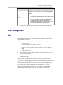
Table 2-5 Description of Web UI user permissions
Accessible
information
User
Auditor
Personal settings
Owned VRR
Personal
settings
Archives and live
streaming recorded
by the owned or
authorized VRR
System Logs
Operation
permissions
Administrator
All pages
Authorized archives
View or edit
View, edit, and
delete
View, edit, and delete
Polycom ® RSS™ 4000 allows up to 200 users to be logged in to the Web UI at the
same time.
Common Operations
List Sorting, Searching, and Refreshing
For all items listed on the Web UI (for example, VRR list, list of archives, user
list, etc.), a unified search bar is provided for users to find specific items,
navigate between pages, and refresh pages. All lists can be sorted by
parameter properties.
2-2
Polycom, Inc.
Charpter 2 - Basic Operations
To search for a target item in the list:
Enter the full name or keyword of the item to be searched for in the
Search… text field above the list, and then click
.
Keyword search is case insensitive.
In the archives search box, you can also type the keywords or tags specified to
an archive.
If you want to return to the full list after searching is complete, clear all the
characters in Search… and click
.
To sort the list:
Click a column header on the list to sort the list in ascending order based
on the property indicated by the header.
Then, when a triangle icon appears, you can click it to sort the list in
descending order.
To refresh the list:
Click
above the list.
Sizing the Pane
To size the pane:
1
Move the mouse pointer to the border of the pane;
2
When the pointer turns into
, drag the border to change the width of
the pane while holding down the left mouse button.
Windows Standard Multiple-Select Operations
While adding or deleting list items, you can perform standard
batch-processing operations by pressing Ctrl + targets or Shift + targets.
Starting a Recording
You can start recording in the Polycom ® RSS™ 4000 system using one of the
following methods:
Polycom, Inc.
•
Start a recording by calling the endpoint from the Polycom® RSS™ 4000
Web UI (only for administrators).
•
Start a recording by calling the Polycom® RSS™ 4000 system using the
endpoint’s remote control.
•
Start a recording by connecting the Polycom® RSS™ 4000 system using
MCU. If the Recording Link function is configured on the Polycom RMX
Series conference platform and the platform is integrated with the
Polycom® RSS™ 4000 system, the Polycom® RSS™ 4000 system can be
2-3
Chapter 2 - Basic Operations
called automatically for recording when a multi-point conference is
being held through MCU. For more information about configuring
Recording Link function on the MCU, refer to the user manual provided
with the MCU.
This part describes how to start recording from the Web UI of the Polycom ®
RSS™ 4000 system and the endpoint.
To start a recording from the Web UI (only for administrators):
1
Enter Polycom ® RSS™ 4000 system IP address in the address bar of the
Web browser to access the Web UI.
2
Enter the username and password in the login page to log in to the
system. Default username and password are both admin.
3
On the Dashboard page (which can also be displayed by clicking
Admin>Dashboard) of the Web homepage, click the Dial out to record
button in the Signaling Connections area.
4
Set the following parameters in the dialog box that opens.
Table 2-6 Dial-out from the Web UI - Parameters Description
Parameter
Description
Signal
Set the H.323 or SIP network type for the system to place a
call. Your choice depends on the call type used by the peer
device.
Address Type
Choose the address type used to call.
Enter the calling address according to the setting of the
address type item.
The system supports entering the calling address with
extended service number in the address box. If call
Polycom® RMX™ series system, you can directly dial into
the conference to be recorded on RMX by entering the
numbers in the following format:
[RMX E.164 prefix][ room number] - Use when every
system has been registered to a gatekeeper
For example, if the RMX prefix is 925 and the room
number is 1001, dial "9251001"
Address
[room number]@ [RMX IP address] - Use when every
system are enabled the SIP
For example, if the room number is 1001 and RMX IP
address is 172.22.30.40, dial "[email protected]"
[RMX IP address]##[room number] - Use when a system
has not been registered to a gatekeeper
For example, if the RMX IP address is 172.22.30.40 and
the room number is 1001, dial "172.22.30.40##1001”
VRR Name
2-4
Click the Select button to select a virtual recording room
(VRR) to be used for recording. You can use the built-in
default VRR. VRR is the basis of recording, and determines
the recording policies. For more information about VRR, refer
Polycom, Inc.
Charpter 2 - Basic Operations
Parameter
Description
to Virtual Recording Room (VRR).
5
Click the OK button to initiate a recording call.
Once the connection between the Polycom ® RSS™ 4000 system and the
endpoint has been successfully established, the recording starts immediately
if the Recording Immediately function has been enabled in the VRR.
Recording connections information and the buttons for pausing and
will be displayed in the Signaling Connections
stopping recording
area. If recording is not started, the Start Recording button
will be
displayed. You can click it to start recording.
To start recording by dialing the Polycom ® RSS™ 4000 system:
1
Enter the E.164 prefix for the Polycom® RSS™ 4000 system on the
remote control to call directly to connect to the Polycom® RSS™ 4000.
If your system or endpoint is not registered to the gatekeeper or is
registered to a SIP server, call the system IP address directly to get
connected.
2
The endpoint screen displays the Polycom® RSS™ 4000 onscreen menu
when it has successfully established the connection with the Polycom®
RSS™ 4000 system. Select the Start Recording>Start using the remote
control to start a recording.
appears during the recording. You can
A blinking recording icon
pause/resume, stop, or cancel the recording using the menu on the
operation page. See Start Recording.
Recordings performed by calling the IP address or E.164 prefix of the
Polycom® RSS™ 4000 system use the default recording parameters of the
system; you can also directly use defined parameters of a VRR to make
recording by adding the VRR's number to the dial-in number. For more
information, see Dialing-in to a VRR to Start Recording.
Playing Back Recorded Files
To play back recorded files stored in the Polycom ® RSS™ 4000, you can
choose one of the following methods:
•
Play back videos via quick code immediately, without entering the user
interface. You can find the quick code in the Properties page of archives.
For details, see Quick Code. This way is available only in H.323 calls
when playing back archives that were not recorded with a multipoint
VRR.
•
Play back from the Polycom ® RSS™ 4000 Web UI.
•
Play back from the Polycom® RSS™ 4000 TV UI. For more information,
see Viewing Archives
To play back videos via quick code immediately:
Polycom, Inc.
2-5
Chapter 2 - Basic Operations
Use the remote control to dial the numbers in following formats which
consist of the system IP address or E.164 prefix and archive quick code:
― [RSS E.164 Prefix][Quick Code]#, used if the system has been
registered to a gatekeeper.
― [RSS IP Address]##[Quick Code]#, used if the system has not been
registered to a gatekeeper.
For example, if the E.164 prefix of Polycom® RSS™ 4000 system is 1234
and the quick code of the recorded file required to be played back is
567890, you should dial 1234567890# to view the video immediately.
If the screen prompts to input the PIN code, you can input the correct PIN
code through the number keypad on the remote control and then press "#".
During the playback of video, you can press the up arrow key on the remote
control to exit playing and return to the file list.
If the bandwidth at which a user endpoint is connected to Polycom® RSS™ 4000 is
lower than the bandwidth used for archives to be played back, videos cannot be
played back on the endpoint.
To play back from the Web UI:
1
Enter Polycom ® RSS™ 4000 system IP address in the address bar of the
Web browser to access the Web UI.
2
Enter the username and password in the login page to log in to the
system.
3
Choose Media>Archives at the upper part of the Web UI to access the
archives page.
4
Select the archive to be played back from the archives list, then click the
Play button
in the Archive Details pane on the right side to play
back the files.
To play back the files, you can also click the Play button in the Archive
Files pane on the right side.
2-6
Polycom, Inc.
3
Ordinary User Configuration
This chapter mainly describes Web configurations that ordinary users
should set after logging into the Polycom® RSS™ 4000 system. For
administrator users, see Chapter Administrator Configuration.
When you log in to the system for the first time using the account and
password assigned by the administrator, a password setting box appears,
prompting you to change your password. You may enter the system after
setting a password that meets the requirements. Once you log in to the
system, the following operations can be performed:
•
Modifying personal settings. See Personal Settings.
•
Viewing and modifying your own Virtual Recording Room (VRR). See
Virtual Recording Room (VRR).
•
Playing back and downloading videos recorded by your own VRR or
authorized archives, or modifying properties of the recorded file. See
Archives.
•
Viewing live streaming performed by you own VRR or authorized live
streaming. See Live Streaming.
•
Starting or stopping your own multicast, and viewing all the
multicasting videos. See Multicast.
Personal Settings
You can set your own account information and change your password on
the personal settings page.
Click My Setting > My Setting in the menu bar at the top of the page to
open the personal settings page.
To modify personal settings:
1
You can configure the following parameters.
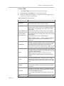
Table 3-7 Personal Setting Parameters Description
Parameter
Description
Full Name
Specifies your full name.
Description
Specifies additional related information.
2
Polycom, Inc.
Click Update to apply these settings.
3-1
Chapter 3 - Ordinary User Configuration
To change password:
1
Click Change My Password in the ACTIONS area on the left side of the
page.
2
In the popup password setting box, enter your old password, your new
password, confirm password, and then click OK.
If successful, you will be prompted that your password has been successfully
changed. Otherwise, you will have to follow instructions to set an
appropriate password.
Only local users created in the Polycom® RSS™ 4000 system can change their
passwords. This function is not available to Active Directory server users.
Virtual Recording Room (VRR)
A Virtual Recording Room (VRR) defines various recording-related
parameters, which are the basis of all recordings. While creating a new user
in the system, a VRR owned by the user is automatically generated. A VRR is
identified by digits, and you can directly dial your own VRR to start
recording by adding your VRR number to the dial-in number.
Click VRR > VRRs in the menu bar at the top of the page to open the VRR
page. In this page you can view user-owned VRR information, including
VRR's name, number, owner, channel and template being used.
In the list, you can search, sort and refresh those VRRs. For specific
instructions, see List Sorting, Searching, and Refreshing.
Dialing-in to a VRR to Start Recording
When an endpoint or MCU tries to connect by directly dialing the IP address
or E.164 prefix of the Polycom® RSS™ 4000 system, the default VRR
parameters will be used to record. You can directly start recording using
recording parameters defined in a VRR by adding the VRR number to the
dial-in number.
To dial VRR through an endpoint's remote control:
3-2
•
If both the Polycom® RSS™ 4000 and the endpoint are registered to a
gatekeeper, the dial-in number is [RSS E.164 prefix][VRR number].
For example, if the Polycom® RSS™ 4000 E.164 is 1234 and your VRR
number is 1000, you may dial "12341000".
•
If both the Polycom® RSS™ 4000 and the endpoint are enabled the SIP,
the dial-in number is [VRR number]@[RSS IP address].
For example, if your VRR number is 1000 and the Polycom ® RSS™ 4000
IP address is 172.21.110.2, you may dial "[email protected]".
•
If the network is not configured with a gatekeeper or SIP server, the
dial-in number is [RSS IP address]##[VRR number].
Polycom, Inc.
Charpter 3 - Ordinary User Configuration
For example, if the Polycom ® RSS™ 4000 IP address is 172.21.110.2 and
your VRR number is 1000, you may dial "172.21.110.2##1000".
Modifying a VRR
You can modify several parameters of your own VRR.
To modify an existing VRR:
1
Click VRR>VRRs in the menu bar at the top of the page.
2
Double-click the VRR to be modified, or click that item and click Edit in
the ACTIONS area on the left side of the page.
3
You can modify the following parameters:
Table 3-8 VRR Parameters Description
Parameter
Description
VRR Name
Specifies a unique name to identify the VRR. You can also
use the default name generated by the system.
Specifies whether to assign a name prefix for the file
recorded with this VRR. The user can organize and identify
a large number of recorded files conveniently with a custom
name prefix.
Use a Custom Name
Prefix for the archive
file name (Name
Prefix+Date+Time)
If this option is selected, enter the name in Custom Name
Prefix. The system will automatically generate the file name
in the following format according to the custom name and
the date and time:
Custom Name_Date_Time_Random Number.
Note: Only letters, figures, _, space or multi-byte characters
can be used for the name prefix, and the length is 4-20
characters.
VRR Number
Specifies a number to identify the VRR. You can directly dial
the VRR to record by adding the VRR number when dialing
the Polycom® RSS™ 4000 system. The number you
entered must be unique and comprised of 4-8 digits.
Owner
VRR owner. It cannot be changed.
Channel
VRR channel. Click the View button for channel details. It
cannot be changed.
Template
The template used by the VRR, which defines basic
recording link parameters. Click the View button for template
details. It cannot be changed.
Key Words
Specifies the keywords for archives recorded with the VRR.
Keywords can be used to search archives easily and quickly
in Archives list (Media>Archives).
You can enter several related words within a length of 128
bytes.
Polycom, Inc.
3-3
Chapter 3 - Ordinary User Configuration
Parameter
Description
Tags
Specifies the tags for archives recorded with the VRR. Tags
can be used to search archives easily and quickly in
Archives list (Media>Archives).
You can enter several related words within a length of 128
bytes.
Specifies whether to enable PIN code protection for the
archive.
Enable PIN Code for
Playback
If a PIN code is set, you must enter the correct PIN code to
play the archive through an endpoint or download the
archive from the web interface. After this option is selected,
you should enter a PIN code consisting of 1-16 digits in PIN
Code.
Note: This option does not apply to playback through the
Web UI.
Recording
Immediately
If this option is selected, the system will immediately start
recording once you connect to the VRR. If deselected, you
may need to manually start recording through the endpoint
interface.
Email Notification
If this option is selected, once the VRR recorded video has
completed its format conversion and is ready for viewing, the
system will send an Email message to the address set here.
Default Recording
Description
If necessary, you can enter additional VRR information in
order to improve identification and classification
management when there are many VRRs.
4
(Optional) Click the Allowed User/Groups tab to set allowed list for that
VRR. Users and groups defined in the allowed list can view or modify
VRR recorded files or live streaming.
Two lists display on the page. The upper one is a selection list that
displays all local users created in the system. You can switch to group
list by clicking the drop-down list on the top of the page.
The following list is the allowed list. All-user group (All_Users) and the
VRR owner are included in the allowed list for VRR by default.
5
Either double-click an item to be allowed in the selection list, or click
that item and click the Add button to add it to the allowed list. The
newly added item is shown in the allowed list, and the already added
items are identified by the
icon in the user list.
― To delete an item from the allowed list, either double-click the item,
or click the item and click the Remove button.
― To authorize a user to edit, check
for that user in the allowed list.
Both add and delete operations support the Windows standard
multiple-select operation.
6
3-4
Click OK to complete modifications to the VRR.
Polycom, Inc.
Charpter 3 - Ordinary User Configuration
Archives
All files recorded by Polycom® RSS™ 4000 system are saved in the Archive
page where ordinary users can only view following types of archives:
•
Files recorded by users’ own VRR
•
Files recorded by the VRR for which the user has been added to the
allowed list
•
Recorded files for which the user has been added to the allowed list.
Viewing Archives
Click Media>Archives in the menu bar at the top of the page to display
Archive page.
On the Archive page, you can view a summary of each archive, including
name, owner, VRR number used, creation time, file size and converting
status. You can also click an archive to show its details in the Archive
Details area on the right of the page:
Table 3-9 Detailed Parameters Description for Archives
Parameter
Description
Name
The name of the archive.
Duration
The duration of the archive.
Video Type
The video protocol used by the archive.
Audio Type
The audio protocol used by the archive.
Content Type
Shows the existence of H.239 dual stream recording.
Description
Shows other additional information.
Play URLs
Lets you copy the URL of playing the archive to the clipboard.
For archives recorded in two different bandwidths, clicking the
Copy link will copy two URLs.
In the list, you can search, sort and refresh archives. For specific instructions,
see List Sorting, Searching, and Refreshing.
Playing Back and Downloading Archives
Polycom® RSS™ 4000 system can save recorded videos into three different
formats, which apply to different kinds of playback:
Polycom, Inc.
•
Raw: Raw bit stream, which is automatically generated after the system
completes the recording. This file can be played back through the
endpoint TV UI interface and downloaded for investigating.
•
WMV: The file in this format is automatically converted into this format
after the system completes recording. This file can be either played back
through the Web UI, or downloaded to your computer to play back. It
will be played back in your computer default player.
3-5
Chapter 3 - Ordinary User Configuration
•
MP4: Can be downloaded to your computer or players that support MP4
files, like the iPhone and iPod. This file can only be generated when MP4
option in the recording template is enabled (see Recording Template).
•
MP3: Can be downloaded to your computer or players that support MP3
files. This file can only be generated when the Generate MP3 Audio File
option in the recording template is enabled (see Recording Template).
There are four statuses for the recorded file to indicate whether this file can
be played or downloaded:
•
Ready: The file can be played and downloaded.
•
Transcoding: The format is being converted, and thus the file is
temporarily unavailable.
•
Waiting: The file is waiting to be converted, and thus temporarily
unavailable.
•
Error: Error converting the format, the file is unavailable.
To play back archives through the Web UI:
1
Click Media>Archives in the menu bar at the top of the page.
2
In the archives list, select the archive to be played back.
3
in the Archive Details area on the right
Click the Play button
side of the page. Windows Media Player opens to play the video.
If the archive is recorded in two different bandwidths, two play buttons
and their bandwidths will display in this area, and you may choose the
appropriate button based on your network condition.
Make sure the archive's format has been converted before playing it back;
otherwise there will be no Play button in the Archive Detail area. You can also
click Archive Files at the right bottom side of the page to expand its property
pane and check the status. If the Play button corresponding to the WMV format
appears as
, indicating that archive is temporarily unavailable, you may need
to wait until the format conversion is completed (i.e. the status is Ready) before
viewing.
If the Email notification function has been enabled for the VRR which is used to
record archives, the system will send you an Email notification automatically
once all archives have been converted and are ready for Web playback. For
more information, see Modifying a VRR.
To download an archive:
1
Click Media>Archives in the menu bar at the top of the page.
2
In the archives list, select the archive to be downloaded.
3
Click Archive Files at the right bottom of the page to expand its
property pane.
4
Click the Download button
corresponding to the target format.
, it means you have to wait until
If the Download button appears as
transcoding is completed in case the archive status is Waiting or
Transcoding.
3-6
Polycom, Inc.
Charpter 3 - Ordinary User Configuration
If the archive has been set with a PIN Code, you must enter the correct
PIN Code before you can download.
5
In the Save Files window that appears, set the download path, and click
Save.
Modifying Archives
You can edit archives recorded by your own VRR or archives that you are
authorized to modify.
To modify archive properties:
1
Click Media>Archives in the menu bar at the top of the page.
2
Either double-click the archive entry to be modified in the archives list,
or click that item and click Edit in the ACTIONS area.
3
If you are authorized to modify the archive, you can modify settings for
the following parameters in the Archive Properties page that appears:
Table 3-10 Archive Properties Description
Parameter
Description
Specifies the name of the archive.
Name
Note: Only letters, figures, _, space or multi-byte characters
can be used for the file name, and the length is 4-20
characters.
Specifies whether to enable PIN code protection for the
archive.
Enable PIN Code
for Playback
If a PIN code is set, you must enter the correct PIN code to play
the archive through an endpoint or download the archive from
the web interface. After this option is selected, you should enter
a PIN code consisting of 1-16 digits in PIN Code.
Note: This option does not apply to playback through the Web
UI.
Description
Specifies additional information related to the archive.
Create Priority
If this option is enabled, it has a higher priority when this
archive is transcoded.
Key Words
Specifies the keywords for archives recorded with the VRR.
Keywords can be used to search archives easily and quickly in
Archives list (Media>Archives).
You can enter several related words within a length of 128
bytes.
Tags
Specifies the tags for archives recorded with the VRR. Tags
can be used to search archives easily and quickly in Archives
list (Media>Archives).
You can enter several related words within a length of 128
bytes.
Polycom, Inc.
3-7
Chapter 3 - Ordinary User Configuration
4
If you want to set a list of users who can view or modify the archive,
click the Allowed Users/Groups tab.
Two lists display on the page. The upper one is a selection list that
displays all local users created in the system. You can switch to group
list by clicking the dropdown list at the top of the page.
The following list is the allowed list. All-user group (All_Users) and
VRR owner are included in the allowed list for archives by default.
5
Either double-click an item to be allowed in the selection list, or click
that item and click the Add button to add it to the allowed list. The
newly added item is shown in the allowed list, and the already added
items are identified by the
icon in the user list.
― To delete an item from the allowed list, either double-click the item,
or click the item and click the Remove button.
― To authorize a user to edit, check
for that user in the allowed list.
Both add and delete operations support the Windows standard
multiple-select operation.
Click OK to complete the setup.
6
Quick Code
A quick code will be generated automatically for every archive after the
system completes a recording. The recorded videos saved in the system can
be played back immediately without accessing the UI by using the remote
control to dial the number with the quick code included.
The quick code is displayed in the Properties page of archives. Click Media>
Archives in the Web Management page, and then double-click an archive.
You can find the quick code in the pop-out page. The quick code cannot be
changed.
When using the quick code to play back files, the dial-in number consists of
the system IP address or the E.164 prefix and the quick code in the following
format:
•
If the system has been registered to a gatekeeper:[RSS E.164
prefix][Quick Code]#
For example, if the E.164 prefix of Polycom® RSS™ 4000 system is 1234
and the quick code of the file to be played back is 567890, dial
1234567890#
•
If the system has not been registered to a gatekeeper:[RSS IP
address]##[Quick Code]#
For example, if the IP address of Polycom® RSS™ 4000 system is 10.1.2.3
and the quick code of the file to be played back is 567890, dial
10.1.2.3##567890#
3-8
The quick code playback is available only in H.323 calls when playing back
archives that were not recorded with a multipoint VRR.
If the bandwidth at which a user endpoint is connected with Polycom® RSS™
4000 is lower than the bandwidth originally used to create the archives, then the
videos cannot be played back successfully on that endpoint's screen.
Polycom, Inc.
Charpter 3 - Ordinary User Configuration
Live Streaming
Polycom® RSS™ 4000 system supports live streaming of video sources, such
as live video conference or dual stream sent by endpoints or MCUs with a
highest resolution of 720p and a maximum bandwidth of 4M. You can view
meeting videos and the second channel of dual stream in real time by
connecting to Polycom® RSS™ 4000 Web UI directly through network,
without using endpoint devices. Those live streaming videos will be saved in
the system.
Live streaming supports dual streaming rates, this allows you to choose the
appropriate bandwidth to view video based on your network condition.
For bandwidth settings, see
Defining a Template.
Starting a Live Streaming
Make sure that live streaming has been enabled for the recording template
you are using before starting live streaming. For details, see
Defining a Template.
Procedure for starting a live streaming is the same as the one for starting
recording. See Dialing-in to a VRR to Start Recording for specific steps.
You cannot pause during live streaming.
Viewing Live Streaming Information
If live streaming is in progress on the system, the current live streaming list
displays on the Live Streaming page. Click Media>Live Streaming in the
menu bar at the top of the page to enter the Live Streaming page.
On this page, ordinary users can only see the following two types of live
streaming content:
•
Live streaming performed by users’ own VRR.
•
Live streaming performed by the VRR for which the user has been
added to the allowed list.
The live streaming list displays live streaming summary, such as live
streaming name, owner, VRR number used, and creation time. You can
also click a specific live streaming content to check its details in the Live
Streaming Details area on the right side of the page.
Viewing Live Streaming Video
When the system starts live streaming, you can view the video being live
streamed in real time on the Live Streaming page.
To view live streaming in progress:
Polycom, Inc.
3-9
Chapter 3 - Ordinary User Configuration
1
Click Media>Live Streaming in the menu bar at the top of the page.
2
Select the live streaming content you want to view in the list, and then
click the Play button
in the Live Streaming Details area on the
right side of the page. Windows Media Player opens to play the video.
If the live streaming content uses two different bandwidths, two Play
buttons with their bandwidths will display in this area, and you may
choose the appropriate bandwidth to play based on your network
condition.
Multicast
Polycom® RSS™ 4000 system supports the video multicast function and can
send video streams to a group of computers at the same time. Users can play
multicast videos by accessing the system's Web Management interface. Only
the use of the Internet Explorer browser is supported.
Before you use the multicast function, make sure that this option has been
activated by your system administrator, and that you have installed
multicast controls in the browser. See (Optional) Installing Multicast Controls.
If using the Windows 7 operating system, you must log in as an administrator in order
to successfully install the controls. Ordinary users cannot install multicast controls.
Multicast of an Archive or a Live Streaming Video
Users can start a multicast from the archives or the live streaming list. The
system supports up to 20 concurrent multicast channels.
To start a multicast:
1
Click Media>Archives in the menu bar at the top of the page.
2
Select the archive for multicasting in the Archives page.
3
Click the button
in the Archive Details area.
, it indicates that this archive is
When the button changes into
undergoing multicast. To stop the multicast, click this button again to
return it to
.
To put a live streaming video into a state of multicast, Click Media>Live
Streaming to enter the Live Streaming page, and then start the multicast (see
the steps described above).
3-10
Polycom, Inc.
Charpter 3 - Ordinary User Configuration
Viewing Multicast Video
All ongoing multicasts are displayed in the multicast list and will disappear
after they end.
To view a multicast video:
1
Click Media>Multicast in the menu bar at the top of the page.
2
Select the video to be viewed from the multicast list.
Click View Multicast in the ACTIONS area on the left of the page. The
system opens Windows Media Player automatically to play the video
selected. Click Stop Multicast to stop the multicast of this video.
Ordinary users can only stop the multicasts they have started.
The system cannot perform cycling of multicast videos. The multicast will end
automatically when the playing of the video ends.
Polycom, Inc.
3-11
4
Administrator Configuration
With full Web configuration management permissions, administrators can
view all recordings and live streaming videos, configure all functions, and
monitor and maintain the system. This chapter mainly introduces Web
configurations designed for administrators. For ordinary users, see the
Chapter Ordinary User Configuration.
By default, Polycom® RSS™ 4000 has one administrator, for which
username and password are both admin. It is recommended that you change
the default password after logging in to the system for the first time to
prevent system intrusions.
Recording Templates
A template is used to define a set of basic recording link parameters, such as
the bandwidth for recording and live streaming, MP4 resolution, and
whether to live stream. All Virtual Recording Rooms (VRR) are created
based on templates. Changing parameters of a template may change the
corresponding recording policies of the VRR using that template.
A default template, named Default_Template, is built in the Polycom®
RSS™ 4000 system. It is selected by default when the system is creating a
VRR. You can modify the default template but cannot delete it.
Viewing Template Information
Click VRR>Templates in the top menu bar of the page to open the template
page.
The page list shows the templates saved on the current system and
associated summary information, including template name, primary channel
and secondary channel bandwidths for recording and live streaming, MP4
resolution, whether to enable live streaming and the people and content
layout when recording dual stream. If the list is longer than one page, you
at the top of
can either turn pages by clicking the button group
the list or jump to a specific page by entering the corresponding page
number in Go to.
In the list, you can search, sort and refresh those templates. For specific
instructions, see List Sorting, Searching, and Refreshing.
Defining a Template
Different templates pre-define different recording link policies for a VRR.
Polycom, Inc.
4-1
Chapter 4 - Administrator Configuration
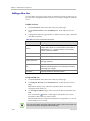
To define a recording template:
1
Click VRR>Templates in the menu bar at the top of the page.
2
Click Add in the ACTIONS area on the left of the page.
3
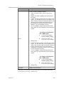
In the new template page that opens you can configure the following
parameters:
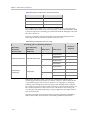
Table 4-11 Defining Template Parameters
Parameter
Description
Name
Specifies a unique name to identify this template.
Maximum Call
Rate
Specifies the maximum bandwidth that can be used by an
endpoint or MCU to connect to the Polycom® RSS™ 4000
system for recording and live streaming.
Primary
Recording and
Streaming Rate
Specifies the bandwidth to be used for video conversion of
recording and live streaming.
Note: The primary rate should not exceed the rate set to
Maximum Call Rate.
Specifies whether to use a secondary lower bandwidth for
video conversion of recording and live streaming.
Secondary
Recording and
Streaming Rate
MP4 Resolution
Video Quality
4-2
Using two different conversion bandwidths gives flexible view
chooses for Users under the different network conditions. The
bandwidth cannot be set higher than Primary Recording and
Streaming Rate. Select None to not use the secondary
bandwidth.
Specifies whether or not to convert recorded files into MP4
format and the resolution after conversion. The converted
files can be downloaded using the Media->Archive page. See
Playing Back and Downloading Archives. Select None to
indicate that the file will not be converted into MP4 format.
Specifies Motion or Sharpness for the video input:
Motion – Give first priority to the motion in the record video.
Accordingly the resolution may be lowered when the network
bandwidth is low. It is best for recording people videos.
Sharpness –Give first priority to the sharpness of the
recorded video. Accordingly the frame rate may be lowered
when the network bandwidth is low. It is usually used for
recording content videos.
Polycom, Inc.
Charpter 4 - Administrator Configuration
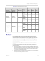
Parameter
Description
Specifies the layout for displaying people and content videos
when recording or live streaming dual stream. Users can
choose from the following layouts:
Video & Content
Layout
Generate an MP3
audio file
Dual window for content: Displays people and content videos
respectively in dual window. This option does not apply to
MP4 files
Single window small content: Displays dual stream in a small
split screen in a single window.
Single window medium content: Displays dual stream in a
medium sized split screen in a single window.
Single window large content: Displays dual stream in a large
split screen in a single window.
Single window no content: Only displays people images
without content.
Single window video/content switch: Alternately displays
people and content in a single window. When content is sent,
the window displays content video. When no content is sent,
the window displays people images.
Specifies whether to convert files into MP3 audio format after
recording. If this option is enabled, the MP3 file icon appears in
the archives in the list of format conversions after the recording
ends. This option is often required to be enabled when
recording an audio-only call.
Note: Polycom® RSS™ 4000 does not support G.728AB or
Siren 14 32K.
Lost Packet
Recovery (LPR)
Specifies whether to enable the Lost Packet Recovery (LPR)
capability.
LPR can effectively improve the decreased video quality
caused by network packet loss. This option takes effect only
when the peer device enables LPR capability as well.
Specifies whether to enable the H.264 High Profile capability.
H.264 High Profile
H.264 high profile requires a much lower bandwidth than the
traditional compression algorithms to achieve the high
definition video, which dramatically reduces the use of network
resources. This option takes effect only when the peer device
enables the H.264 High Profile capability as well.
Note: H.264 High Profile is available only in H.323 calls.
Polycom, Inc.
Live Streaming
Specifies whether to enable live streaming. If this option is
enabled, the system will live stream videos sent from an
endpoint or MCU, and users can view them in real time by
connecting to the Web UI of the system. For information on live
streaming, see Live Streaming.
Restrict the
recording to
CIF/SIF resolution
Specifies whether to restrict the bandwidth within the range of
1024Kbps. No matter what functions the endpoint has, calls
made with this template will be recorded using CIF/SIF
resolution.
Backup medias
Specifies whether to specify a designated backup path on the
4-3
Chapter 4 - Administrator Configuration
Parameter
Description
using this
template to:
FTP server for all files recorded with this template. This option
is only available when users have configured an FTP server for
data backup. (See FTP Server Configuration ). If this option is
selected, it is required to enter the path of the backup file in
Media Path. Make sure your FTP server can identify this path.
If no backup path is set in the template, archives will be backed
up to the default path set in the Admin> Data Backup/Restore
page.
4
Click OK to complete the setup.
The new template can be viewed in the template list.
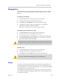
Managing Templates
You can edit or delete a created template.
To edit or delete a created template:
1
Click VRR>Templates in the menu bar at the top of the page.
2
Click the template entry to be changed in the template list.
3
In the ACTIONS area on the left side of the page, click Edit or Delete to
modify or delete the template.
When you delete a user-defined template, all VRRs using that template will be
automatically changed to use the default template. However ongoing recording
performed by these VRRs will not be affected.
Virtual Recording Room (VRR)
A Virtual Recording Room (VRR) is created based on recording templates. It
defines various recording-related parameters, which are the basis of all kinds
of recordings. A VRR is identified by digits, and you can directly start
recording using specified VRR parameters by adding the VRR number to the
dial-in number.
A default VRR, named Default_VRR, is built in the system. When an
endpoint or MCU tries to connect by directly dialing Polycom® RSS™ 4000
system IP address or E.164 prefix, default VRR parameters will be used for
recording. You can modify the default VRR but cannot delete it.
Defining a VRR
You can pre-define a variety of record types for each recording by defining
the VRR, to avoid over and over configuring the same recording parameters.
4-4
Polycom, Inc.
Charpter 4 - Administrator Configuration
To define a VRR:
1
Click VRR>VRRs in the menu bar at the top of the page.
2
Click Add in the ACTIONS area on the left of the page.
3
In the new VRR page that appears, configure the following parameters
(* indicates mandatory parameters):
Table 4-12 Defining VRR Parameters
Parameter
Description
VRR Name
Specifies a unique name to identify the VRR. You can also
use the default name generated by the system.
Specifies whether to assign a name prefix for the file
recorded with this VRR. The user can organize and identify a
large number of recorded files conveniently with a custom
name prefix.
Use a Custom Name
Prefix for the archive
file name (Name
Prefix+Date+Time)
If this option is selected, enter the name in Custom Name
Prefix. The system will automatically generate the file name
in the following format according to the custom name and the
date and time:
Custom Name_Date_Time_Random Number.
Note: Only letters, figures, _, space or multi-byte characters
can be used for the name prefix, and the length is 4-20
characters.
VRR Number
Owner
Specifies a number to identify the VRR. You can directly dial
the VRR to record by adding the VRR number when dialing
the Polycom® RSS™ 4000 system. The number you
entered must be unique and comprised of 4-8 digits. You can
also use the number automatically generated by the system.
Specifies the owner of this VRR. The default owner is admin.
In addition to the administrator, only the VRR owner can view
and modify VRR parameters.
Note: Each VRR must belong to a user. If the user is
deleted, all VRRs owned by that user will be automatically
deleted.
Channel
Specifies the VRR channel. A channel is used to classify a
large number of videos when the Polycom® RSS™ 4000 is
integrated with Polycom Video Media Center™ (VMC) 1000
V2.0.
Template
Specifies the VRR template. The template defines the basic
recording link parameters. The default template is selected
by default.
Key Words
Specifies the keywords for archives recorded with the VRR.
Keywords can be used to search archives easily and quickly
in Archives list (Media>Archives).
You can enter several related words within a length of 128
bytes.
Tags
Polycom, Inc.
Specifies the tags for archives recorded with the VRR. Tags
4-5
Chapter 4 - Administrator Configuration
Parameter
Description
can be used to search archives easily and quickly in
Archives list (Media>Archives).
You can enter several related words within a length of 128
bytes.
Specifies whether to enable PIN code protection for the
archive.
Enable PIN Code for
Playback
If a PIN code is set, you must enter the correct PIN code to
play the archive through an endpoint or download the
archive from the web interface. After this option is selected,
you should enter a PIN code consisting of 1-16 digits in PIN
Code.
Note: This option does not apply to playback through the
Web UI.
Recording
Immediately
If this option is selected, the system will immediately start
recording once you connect to the VRR. If deselected, you
may need to manually start recording through the Web UI or
the endpoint interface.
Email Notification
If this option is selected, once the VRR recorded video has
completed its format conversion and is ready for viewing, the
system will send an Email message to the address set here.
Default Recording
Description
If necessary, you can enter additional VRR information, such
as the owner and usage, in order to improve identification
and classification management when there are many VRRs.
4
(Optional) Click the Allowed User/Groups tab to set allowed list for that
VRR. Users and groups defined in the allowed list can view or modify
VRR recorded files or live streaming. For user and group settings, see
User Management.
Two lists display on the page. The upper one is a selection list that
displays all local users created in the system. You can switch to group
list by clicking the dropdown list at the top of the page.
The lower part of the list is the allowed list. By default, the VRR created
by an administrator has a group named All_Users in its allowed list.
That means all users are allowed to view recorded files and live
streaming.
5
Either double-click an item to be allowed in the selection list, or click
that item and click the Add button to add it to the allowed list. The
newly added item is shown in the allowed list, and the already added
items are identified by the
icon in the user list.
― To delete an item from the allowed list, either double-click the item,
or click the item and click the Remove button.
― To authorize a user to edit, check
for that user in the allowed list.
Both add and delete operations support the Windows standard
multiple-select operation.
6
4-6
Click OK to complete VRR configuration.
Polycom, Inc.
Charpter 4 - Administrator Configuration
Once a VRR is created, the VRR owner is automatically added to the allowed list
and authorized to view and edit.
Administrators are not limited by the allowed list, and have always permissions to
view and edit VRR recorded files or live streaming.
Dialing-into a VRR to Start Recording
You can start recording using a user-defined VRR in one of the following
two ways: directly dialing in the VRR through an endpoint remote control or
dialing out from VRR using the Web Management page to connecting the
endpoint.
To dial in VRR through an endpoint's remote control:
•
If the Polycom® RSS™ 4000 and the endpoint are both registered to a
gatekeeper, the dial-in number is [RSS E.164 suffix][VRR number].
For example, if the Polycom® RSS™ 4000 E.164 is 1234 and your VRR
number is 1000, you may dial "12341000".
•
If the Polycom® RSS™ 4000 and the endpoint are both registered to a
SIP server, the dial-in number is [VRR number]@[RSS IP address].
For example, if your VRR number is 1000 and the Polycom ® RSS™ 4000
IP address is 172.21.110.2, you may dial "[email protected]".
•
If the network is not configured with a gatekeeper or SIP server, the
dial-in number is [RSS IP address]##[VRR number].
For example, if the Polycom ® RSS™ 4000 IP address is 172.21.110.2 and
your VRR number is 1000, you may dial "172.21.110.2##1000".
To dial-out from VRR using Web Management page:
For detailed instructions, see To start recording from the Web UI in the section
Starting a Recording.
If the Polycom® RSS™ 4000 system is configured in connection with a Polycom RMX
series system through the recording link, you can specify the VRR to be used by
adding the VRR number in the Recording Link field on the Polycom RMX system.
For more information, refer to the Polycom RMX system Administrator’s Guide.
Managing VRRs
An administrator can edit or delete a created VRR.
To edit or delete a created VRR:
Polycom, Inc.
1
Click VRR>VRRs in the menu bar at the top of the page.
2
Click the VRR entry to be edited in the VRR List.
3
In the ACTIONS area on the left side of the page, click Edit or Delete to
modify or delete the VRR.
4-7
Chapter 4 - Administrator Configuration
The archives recorded with a VRR should be deleted before you can delete the VRR.
Multipoint Recording
Multipoint recording allows you to set up a conference between two sites
and record or live stream the conference video without needing a MCU. The
multipoint recording is activated when two participants connect to a
multipoint recording room on the Polycom® RSS™ 4000 system.
Each participant in a multipoint recording sees the peer site image. If only
one participant connects, the participant’s screen displays the loopback
image. When the recording or live streaming is ended, the system generates
the video files with the combined images of two sites displaying side-by-side
or alternately. If H.239 content is being sent during a recording, the content
image is also shown in the conference and recorded.
During a multipoint recording, both sites can display and interact with the
system TV user interface for managing the recording, but only one site can
control at a time. For more information about the TV UI, refer to TV User
Interface Operation.
Polycom RMX series systems that support the Recording Link can be
connected to the multipoint meeting room as a participant as well.
The multipoint recording has the following limitations:
The quick code is not supported for archives generated from the multipoint
recordings for playback.
Participants in a multipoint recording cannot view archives stored in the system
through the TV interface.
Multipoint Recording and Live streaming Resource Usage
A multipoint recording utilizes the same resources as a single point
recording. The system supports up to 15 multipoint recording sessions
simultaneously.
For a multipoint recording with live streaming, the resources used by the
system vary according to the video resolution, call rate, and the video layout
of the recording. Different models of the Polycom® RSS™ 4000 have
different resource capacity. The following table shows the relationship
between the streaming properties and maximum number of multipoint live
streaming the different model systems support:
4-8
Polycom, Inc.
Charpter 4 - Administrator Configuration
Table 4-13 Multipoint Live Streaming Maximum Capacity
Multipoint Live Streaming Properties
Recording
Live Streaming
Rates
Resolution
Resolution
Used
(People Video)
(WMA File)
CIF / 4CIF /
720P
CIF / 4CIF /
720p
30fps
30fps
Multipoint Maximum Capacity
1
2
1080p 30fps/
720p 30fps
1
720p 60fps
2
Video Layout
Small
Medium
Large
Single Window
2
3
4
Dual Window
1
1
2
Single Window
1
1
2
Dual Window
1
1
1
Single Window
1
2
2
Dual Window
1
1
1
Single Window
1
1
1
Dual Window
1
1
1
Creating a Multipoint Recording Room
You can create a multipoint recording room by defining a multipoint VRR in
the Polycom® RSS™ 4000 system. Dialing into a multipoint VRR sets up a
multipoint recording room between the two sites.
To define a multipoint VRR:
1
Click VRR> Multipoint VRRs in the menu bar at the top of the page.
2
In the ACTIONS area on the left side of the page, click Add.
3
On the Add VRR page, configure the following settings specific to
multipoint recording:
Table 4-14 Defining Multipoint VRR Parameters
Parameter
Description
Specifies the layout mode to be used for displaying the images
of two sites in the multipoint conferences after the video is
recorded.
Lecture Mode: displays the lecture in the full screen. When a
participant keeps speaking for 10 seconds, the system elects
him or her as a lecture. The lecture switches between the two
sites through the audio activation.
CP Mode: displays the video of two sites side by side on the
screen.
Layout Mode
Enable PIN Code
for Playback and
Room Entry
Polycom, Inc.
Specifies whether to set a PIN code for protecting playback and
recording room entry.
Once a PIN code is set, users are required to enter the proper
4-9
Chapter 4 - Administrator Configuration
Parameter
Description
code before they play back an archive through the onscreen
interface, download an archive from the web interface or enter
a recording room. A valid PIN code should consist of 1-16
digits.
4
For other options in the page, refer to Defining a VRR.
5
Click OK to complete the configuration.
Reservation VRR
Reservation VRR can send out the email notification with the predefined
conference start time and view link before a live streaming actually occurs,
which lets you easily inform the audience of upcoming conference and direct
them to the waiting hall for viewing. Reservation VRR does not reserve any
video resources.
Creating a Reservation VRR
A reservation VRR should be created based on a template that has live
streaming enabled. You can create up to 20 concurrent reservation VRRs in
the system. The system sends out a notification when the reservation VRR is
created. Make sure your system has been set with the accurate local time so
it indicates the correct conference start time in the email notification.
To create a reservation VRR:
1
Click VRR> Reservation VRRs in the menu bar at the top of the page.
2
In the ACTIONS area on the left side of the page, click Add.
3
On the Add VRR page, configure the following settings specific to the
reservation VRR:
Table 4-15 Defining reservation VRR Parameters
Parameter
Description
Template
Specifies a template with live streaming enabled.
Permanent
Reservation
Specifies whether the VRR is available permanently, even if no
device calls in.
Start Time
Specifies the start time of the conference that you want to
present in the email notification. This option is available when
Permanent Reservation is deselected.
Idle Time to Live
Specifies an idle time in range of 5-120 minutes. The VRR is
removed from the system automatically in the following
scenarios.
4-10
There is no device dial into the VRR for the time set here
after the Start Time arrives.
Polycom, Inc.
Charpter 4 - Administrator Configuration
Parameter
Description
The device disconnected from the VRR for the time set here.
Specifies whether to send email notification to the address set
here in the following scenarios.
The reservation VRR is created. The Email includes
information of the conference start time and the view link.
The conference recording is completed. The Email includes
information of archive details and links for playback and
download.
Email Notification
4
For other configuration fields in the page, refer to Defining a VRR.
5
Click OK to complete the configuration.
The new VRR is displayed in the reservation list and at the same time a new
item is added in the live streaming list. If you click the view link before the
live streaming starts, your window media player displays a waiting image.
Channel
You can customize video channels on the Polycom® RSS™ 4000 to classify
videos according to subjects. When integrated with Polycom Video Media
Center™ (VMC) 1000 V2.0, videos recorded on the Polycom® RSS™ 4000
can be imported into VMC and classified according to their channels, to
facilitate on-demand business management.
A default channel, named Default_Channel is built in the system. You
cannot change its name or delete it.
To setup a channel:
1
Click VRR>Channels in the menu bar at the top of the page.
2
Click Add in the ACTIONS area on the left of the page.
3
In the add channel page, enter the channel category name, and any
additional related information if necessary.
4
Click OK to complete the setup.
To edit or delete a created channel:
1
Click VRR>Channels in the menu bar at the top of the page.
2
Click the channel entry to be edited in the channel list.
3
In the ACTIONS area on the left side of the page, click Edit or Delete to
modify or delete the channel.
Once a channel is deleted, VRRs belonging to that channel are automatically changed
to belong to the default channel.
Polycom, Inc.
4-11
Chapter 4 - Administrator Configuration
Recording Setting
Recording Setting page provides supplementary settings for recording. You
may need to configure these options, if needed.
To configure recording setting options:
1
Click System Config>Recording Setting in the menu bar at the top of
the page.
2
On Recording Setting page, configure the following parameters:
Table 4-16 Defining Recording Setting Parameters
Parameter
Description
Continue
recording if no
resource for live
streaming
If this option is selected, the system which is in live streaming
mode will automatically switch to recording mode in case of
insufficient resources. In this case, you cannot continue to view
the video in real time through the Web. However, you can play
back the video once recording and format conversion are
completed by the system. If deselected, the system will reject
all live streaming requests when there is no live streaming
resource.
Enable 1080p
H.323 recording
with live streaming
Specifies whether to enable the 1080p capability of the system
for recording with live streaming.
Enable Recording
Tone
Specifies whether to play the recording tone every 10 seconds
during a recording.
Key Frame
interval
Specifies the fast forward/backward intervals when playing
back recorded files on an endpoint. For example, if it is set to 1
minute, the system will set one node every minute when
recording. When pressing the Fast forward button, the video
playback will jump to the nearest node content from the current
location.
Specifies how AES encryption is enabled for H.323
connections:
Required For All Calls enables the AES encryption for all
H.323 calls, including video and audio only calls. This option
requires the device to connect the system with AES enabled,
otherwise, the connection cannot be set up.
Required For Video Calls enables the AES encryption for
all H.323 video calls. This option requires the device to
connect the system with AES enabled, otherwise, the
connection cannot be set up.
When Available enables the AES encryption for H.323
connections when the peer device enables the AES option,
and vice versa.
AES
Note: AES encryption is available only in H.323 calls. You need
to choose “When Available” for setting up SIP connections
successfully.
4-12
Polycom, Inc.
Charpter 4 - Administrator Configuration
Parameter
Description
Support AES
256-Bits key for
encryption
Specifies whether to enable the 256-bit key for AES encryption.
If not selected, the AES uses 128-bit key for encryption by
default.
Archives
The administrator can view and modify all recorded files currently archived
by the system through the Web UI, and delete and re-transcode archives. For
operation descriptions of viewing, playing back and downloading archives
as well as modifying properties of archives, see Ordinary User Configuration
in Chapter Archives.
Re-transcoding Archives
For archives which have already been saved in the page, the administrator
can re-transcode them. The re-transcoding can be performed in accordance
with the current parameters of VRRs used by the archives.
Re-transcoding is not allowed when the archive is in the process of being
transcoded.
To re-transcode archives:
1
Click Media>Archives in the menu bar at the top of the page.
2
In the archives list, select the file to be re-transcoded.
3
Click Recreate Archives at the bottom right side of the page.
4
The existing files will be deleted after the file re-transcoding starts. Click
Yes to confirm the re-transcoding.
When the Play button appears in Archive Details area on the right side of
the page, it indicates that the re-transcoding of files has been completed.
Live Streaming
For description of the live streaming function, see Ordinary User
Configuration in Chapter Live Streaming. The administrator can view all
ongoing live streaming videos.
Live Streaming Resources Usage
The number of resources supported by the Polycom® RSS™ 4000 system for
live streaming the video depends on the system model you purchased. The
following table shows the relationship between the model and the resources
it supports.
Polycom, Inc.
4-13
Chapter 4 - Administrator Configuration
Table 4-17 Device model and live streaming resources
Model
Resources Required
Small
4
Medium
6
Large
8
The combination of frame rate, resolution, number of rates used and video
layout affects the number of resources required on the Polycom® RSS™ 4000
system to support live streaming. For information about setting the rates and
the video layout, see
Defining a Template. The following table shows the relationship between
those aspects and the amount of resources that are used.
Table 4-18 Live streaming resources usage
Recording with Live Streaming Properties
Recording
Resolution
Live Streaming
Resolution
(People Video)
(WMV File)
Rates Used
Resources
Required
Video Layout
Single Window
1
Dual Window
2
Single Window
2
Dual Window
4
Single Window
2
Dual Window
3
Single Window
3
Dual Window
5
1
CIF/4CIF/720p 30 fps
CIF/4CIF/720p 30 fps
2
1
1080p 30fps/
720p 60 fps
720p 30 fps
2
Referring to the above table, you can easy calculate the number of live
streams supported by the system in concrete scenarios. Take a Small model
system that supports four resources. If there is an ongoing live streaming
sending video at 720p 30 fps and recording video at 1080p 30 fps/720p 60
fps, using two rates and single window layout, it occupies three resources on
the system. Then there is one resource free, which allows for running one
live stream at CIF/4CIF/720p 30 fps, using a single rate and single window
layout concurrently.
The following table shows the maximum capacity of the Polycom® RSS™
4000 systems when perform the live streaming of different parameters:
4-14
Polycom, Inc.
Charpter 4 - Administrator Configuration
Table 4-19 Live streaming maximum capacity
Recording with Live Streaming Properties
Recording
Resolution
Live Streaming
Resolution
(People Video)
(WMV File)
Rates Used
Maximum Capacity
Video
Layout
Small
Medium
Large
Single
Window
4
6
8
Dual
Window
2
3
4
Single
Window
2
3
4
Dual
Window
1
1
2
Single
Window
2
3
4
Dual
Window
1
2
2
Single
Window
1
2
2
Dual
Window
1
1
1
1
CIF/4CIF/
CIF/4CIF/
720p 30 fps
720p 30 fps
2
1
1080p 30fps/
720p 60 fps
720p 30 fps
2
Multicast
Polycom® RSS™ 4000 system supports the multicast function and can
perform the one-to-many transmission of video streams. The system only
needs to send the video streams once so that multiple computers can
simultaneously share live streaming or recorded videos, so as to greatly
reduce the demand for transmitting network video streams and save the
network bandwidth.
Polycom® RSS™ 4000 supports the simultaneous multicast of up to 20
channels.
To use the multicast function successfully, the following conditions are
required to be met:
Polycom, Inc.
•
The multicast function is activated in the Polycom® RSS™ 4000 system.
The multicast function is optional. It is available only after you purchase
the license for this function and the system is activated. Please contact
your supplier to obtain this function.
•
Multicast controls are installed on the computer to receive the multicast.
See (Optional) Installing Multicast Controls.
4-15
Chapter 4 - Administrator Configuration
Routers and switches in the network of client computers are configured
correctly to support the IP multicast communication with Polycom®
RSS™ 4000 system.
•
Configuring Multicast
Before you use the system to perform the multicast, it is necessary to
configure parameters on the Multicast page.
To configure multicast parameters:
1
Click System Config>Multicast Setting in the menu bar at the top of
the page.
2
On the Multicast Setting page, configure the following parameters:
Table 4-20 Description of Multicast Setting Parameters
Parameter
Description
Auto Multicast for Live
Streaming
If this option is selected, when there is a live streaming
started, the system will also multicast the live video
automatically at the same time.
Multicast IP Pool
Starting Address
Specifies the initial IP address of the multicast address
pool. The system will use 20 consecutive addresses
starting with this address to perform the multicast. Make
sure the address pool entered is within the range of
233.0.0.0 to 238.255.255.236.
Multicast Port
Specifies the multicast port. All multicast video streams
use the same port as set here.
Multicast Operation
For how to start and stop the multicast and how to view multicast videos,
see Ordinary User Configuration in Chapter Multicast of an Archive or a Live
Streaming Video. While multicast operations are roughly the same for the
administrator and ordinary users, the difference is that the administrator can
stop all ongoing multicasts and ordinary users can only stop the multicasts
which they have started.
Network Service
IP Setting
Polycom® RSS™ 4000 system supports both IPv4 and IPv6 network
communications. On the IP Setting page, you can configure parameters to be
used for network communication, including system IP address, DNS server,
NAT server and speed/duplex modes for LAN ports.
4-16
Polycom, Inc.
Charpter 4 - Administrator Configuration
To configure the IP settings:
1
Click System Config>IP Setting in the menu bar at the top of the page.
2
On the IP Setting page, configure the following parameters:
Table 4-21 Signaling Network Parameters Description
Parameter
Description
Obtain an IP Address
Automatically (DHCP)
Specifies the system to obtain an IPv4 automatically.
Using the following IP
Address
Specifies the system to use a static IPv4 address. You
need to manually enter the IP address and subnet mask.
Enable IPv6
Specifies whether to enable IPv6 function.
Obtain an IP Address
Automatically (IPv6)
Specifies whether to obtain the IPv6 address automatically
using Stateless Address Auto-configuration (SLAAC).
Using the following IP
Address (IPv6)
Specifies whether to configure a static IPv6 address
manually. You need to enter the link local address, site
local address and global address.
Enable ICMP V6 DAD
Specifies whether to enable the Duplicate Address
Detection (DAD) to ensure the IPv6 address set to the
system is unique in the local network.
Enable ICMP Echo
Specifies whether to enable the system to respond to an
ICMP echo request (Ping) sent from other devices in the
network. In some high-security environments, you may
need to disable this option to protect the system from Ping
attacks.
LAN Speed
Specifies the speed/duplex modes for LAN port. Supports
the 10/100M Full Duplex or Half Duplex mode and the
1000M network. Select Auto to use auto-negotiation.
Note: Obtaining an IP Address Automatically is not
recommended. For best results, the system should be
configured with a static IP address.
Note: When setting LAN port speed, contact your network
administrator to ensure that the switch link rate matches
the system port speed.
3
In the General System Network Settings area, configure the following
settings:
Table 4-22 General System Network Parameters Description
Polycom, Inc.
Parameter
Description
Enable Destination
Unreachable Message
Specifies whether to enable the system to forward the
ICMP destination unreachable messages that come from
other network devices when the system is configured to
serve as a router.
Host Name
Specifies the host name of the system.
Domain
Specifies the domain name of the system.
4-17
Chapter 4 - Administrator Configuration
Parameter
Description
Gateway
Specifies the address of the interface to use for accessing
the IPv4 gateway.
Default IPv6 Gateway
Specifies the address of the interface to use for accessing
the IPv6 gateway.
Preferred/Alternate
DNS Server Address
Specifies the preferred or alternate DNS server addresses
here for the system to resolve domain names.
NAT Public (WAN)
Address
Specifies whether to enable the Network Address
Translation (NAT). NAT environments use private internal
IP addresses for devices within the network, while using
one external IP address to allow devices on the LAN to
communicate with other devices outside the LAN. Enter the
external IP address here if this option is enabled.
Gatekeeper
A gatekeeper manages functions such as bandwidth control and admission
control. The gatekeeper also handles address translation, which allows users
to make calls using static aliases instead of IP addresses that may change
each day.
To configure the system to use a gatekeeper:
1
Click System Config>Signaling Setting> H.323 in the menu bar at the
top of the page.
2
Set the following parameters in the gatekeeper page:
Table 4-23 Gatekeeper Parameters Description
Parameter
Description
Register to Gatekeeper
Indicates whether or not to register to the gatekeeper. You
must check this option to set the following parameters.
Primary (Alternate)
Gatekeeper
Note: The alternate gatekeeper will only be used when the
primary gatekeeper is not available.
Gatekeeper IP Address
Specifies the IP address for the primary (or alternate)
gatekeeper.
Gatekeeper Port
Specifies the port number for the primary (or alternate)
gatekeeper.
Register’s User
Information to
Gatekeeper
4-18
Indicates whether the system has been registered to the
primary (or alternate) gatekeeper.
Specifies whether to register the system to Polycom DMA
7000 for H.235 .0 Authentication.
When H.235.0 authentication is enabled, the gatekeeper
ensures that only trusted endpoints are allowed to access
the gatekeeper.
Polycom, Inc.
Charpter 4 - Administrator Configuration
Parameter
Description
Gatekeeper User
Specifies the user name for registration with Polycom DMA
server.
Gatekeeper Password
Specifies the password for registration with Polycom DMA
server.
System Prefix/E164.
Specifies the E.164 number for the system.
System H.323Alias
Specifies the H.323 alias for the system.
3
Click Update and confirm to restart the system to apply the setting.
SIP
If your network supports the Session Initiation Protocol (SIP), you can use
SIP to connect IP calls. The Polycom® RSS™ 4000 system supports only the
integration with Polycom DMA SIP server.
To configure the SIP settings:
1
Click System Config>Signaling Setting>SIP in the menu bar at the top
of the page.
2
Set the following parameters in the SIP page:
Table 4-24 SIP Parameters Description
Parameter
Description
Enable SIP
Specifies whether to enable the SIP in the system. You
need to set the SIP server-related parameters after this
function is enabled.
Transport Type
Specifies the transport layer protocol used for
communicating with the SIP server. It needs to be
consistent with the protocol supported by the SIP server.
Register to SIP Server
Specifies whether to register the system to the Polycom
DMA SIP server.
SIP Server
Specifies the IP address, connection port, and domain
name of the SIP server for registration service.
Register User Information
Specifies the user name and password that authenticates
the system to the SIP Server.
Outbound Proxy Server
For communication with the SIP server when the system
is configured on the internal network, an outbound proxy
server is required to implement traversal of the firewall or
NAT. In this case, you need to set the IP address and port
number for the outbound proxy server.
3
Polycom, Inc.
Click Update and confirm to restart the system to apply the setting.
4-19
Chapter 4 - Administrator Configuration
QoS
Quality of Service (QoS) is very important in transmission of
high-bandwidth audio and video data. You can use QoS to test and
guarantee the following parameters:
•
Average packet delay
•
Delay variation (jitter)
•
Error rate
To specify QoS parameters:
1
Click System Config>Signaling Setting>QoS in the menu bar at the top
of the page.
2
On the QoS page, configure the following parameters:
Table 4-25 QoS Parameters Description
Parameter
Description
Enable QoS
Select this option to enable configuration of the QoS
settings. When un-checked, the system uses the default
QoS settings.
DiffServ and Precedence are two methods for encoding
packet priority. The priority set here for audio and video
packets should match the priority set in the network
routers.
Type
Differv: Select when the network router uses Differv for
priority encoding. If this option is selected, enter values
in the Audio and Video fileds. The value range is 0-63.
Note: If you select DiffServ but your router does not
support this standard, IP packets queue on the same
communication links with data packets. This
non-prioritized queueing greatly increases the latency and
jitters in their delivery and can negatively impact
performance.
Precedence: Select this option when the network router
uses Precedence for priority encoding, or when you are
not sure which method is used by the router.
Precedence should be matched with None in the Tos
field. The value range is 0-5. If this option is selected,
enter values in the Audio and Video fields. The value
range is 0-5.
Note: Precedence is the default mode as it is capable of
providing priority services to all types of routers and is
currently the most common mechanism.
Specify the priority for audio and video IP packets.
Audio / Video
4-20
The recommended priority is 4 for audio and video to
ensure that the packet delay for both is the same, that
audio and video packets are synchronized, and to ensure
lip and audio synchronization (lip sync).
Polycom, Inc.
Charpter 4 - Administrator Configuration
Parameter
Description
Select the Type of Service (ToS) that defines optimization
tagging for routing the conference audio and video
packets.
Delay: The recommended default for video
conferencing; prioritized audio and video packets tagged
with this definition are delivered with minimal delay.
None: No optimization definition is applied. This is a
compatibility mode in which routing is based on
Precedence priority settings only. Select None if you do
not know which standard your router supports.
ToS
3
Click Update and confirm to restart the system to apply the setting.
User Management
User
Users who are defined in the Polycom® RSS™ 4000 system can log in to the
Web Management pages to complete authorized operations. The system
supports three user levels:
•
User: Who can only view and edit limited pages, including:
― Personal settings
― Password modification (local user only)
― Owned VRR
― Archives and live streaming recorded by the owned or authorized
VRR
― Authorized archives
•
Auditor: Who can only audit and manage system logs, delete logs, and
set personal information.
•
Administrator: Who can perform the most operations, and can view and
configure all pages.
If the system is configured with an Active Directory (AD) server, users
defined on the AD can log in to the Polycom® RSS™ 4000 system as
ordinary users. When logging in to the system for the first time, AD users are
automatically added to the user list in the Polycom® RSS™ 4000 system.
By default, Polycom® RSS™ 4000 has one administrator, for which
username and password are both admin. It is recommended to define
different user management permissions as required, and change the
administrator's default password to prevent system from invasions.
Polycom, Inc.
4-21
Chapter 4 - Administrator Configuration
Viewing Users
Click User>Users in the menu bar at the top of the page to enter Users page.
Users page displays a list of defined users in the current system and
associated summary information:
Table 4-26 Description for User List Information
4-22
Parameter
Description
User ID
User ID used for Web login.
Full Name
User full name.
Domain
User domain. LOCAL indicates that the user is a local user
created in the system.
Role
User roles: Administrator, Auditor or User. Different roles
determine the user operation permissions after logging in
to pages.
Polycom, Inc.
Charpter 4 - Administrator Configuration
Parameter
Description
A user can have four different statuses:
Active: User status is active. User can log in to the
system.
Disable: User status is disabled. User cannot log in to
the system.
Locked: User status is locked. User cannot log in to the
system. If a user failed to login for a set condition, that
user is locked by the system automatically. And the user
cannot log in to the system until lock has timed out or
the administrator has changed the status to Active
manually. For more information, see Ping
You can use Ping to verify that the Polycom® RSS™
4000 system can communicate with another node in the
network.
To run Ping on the Polycom®
RSS™ 4000 system:
Status
1
Click System Config >
Security Setting > Ping.
2
Enter an IP address or
host name and click Ping.
Security Policy.
Inactive: User status is inactive. User cannot log in to the
system. If a user does not log in to the system for a set
period of time, that user status automatically switches to
Inactive. User cannot log in to the system until the
administrator has changed the status to Active manually.
For more information, see Ping
You can use Ping to verify that the Polycom® RSS™
4000 system can communicate with another node in the
network.
To run Ping on the Polycom®
RSS™ 4000 system:
Description
3
Click System Config >
Security Setting > Ping.
4
Enter an IP address or
host name and click Ping.
Security Policy.
Additional user information.
In the list, you can search, sort and refresh users. For specific instructions,
see List Sorting, Searching, and Refreshing.
Polycom, Inc.
4-23
Chapter 4 - Administrator Configuration
Adding a New User
You can add a local user to the system or import users from an AD server to
the system for management if the system is successfully configured with AD
server.
To add a local user:
1
Click User>Users in the menu bar at the top of the page.
2
Click Add Local User in the ACTIONS area on the left side of Users
page.
3
Configure the following parameters on Add Local User page (* indicates
mandatory options):
Table 4-27 Local User Parameters Description
Parameter
Description
User ID
Specifies the user ID used for Web login. User ID must be
unique with a length of 1-128 characters, and consist of
alphanumeric or "_" symbol characters. Once created,
user ID cannot be modified.
Full Name
Specifies the user's full name.
Password
Specifies the login password.
Confirm Password
Specifies the confirm password which must be identical to
the login password.
Role
Specifies the user role: Administrator, Auditor or User.
Different roles determine the user operation permissions
after logging in to pages.
Description
Specifies additional related information.
To import an AD user:
1
Click User>Users in the menu bar at the top of the page.
2
Click Import AD User in the ACTIONS area on the left side of Users
page.
This button displays only when the system has been successfully
configured with AD server.
3
On the Import AD User page, select a user from the list, and then click
OK.
button on that page to refresh the list, or enter
You can click the
username in the text box to start a search.
The standard Windows keyboard operations are supported, so you can
add multiple users at a time.
As a new user is added, the system automatically creates a VRR owned by that user,
and it can be viewed by entering the VRR>VRRs Page.
4-24
Polycom, Inc.
Charpter 4 - Administrator Configuration
Managing Users
Administrator can modify local user information and password, or delete
user. For an AD user, the administrator can only edit user status or delete
that user.
To modify user information:
1
Click User>Users in the menu bar at the top of the page.
2
Select the user entry to be modified in the user list.
3
Click Edit in the ACTIONS area on the left side of the page.
4
On the Edit User page, set the user's full name, role, additional
information and status, and then click OK.
If the user is an AD user, you can only modify its status.
To modify user password (local user only):
1
Click User>Users in the menu bar at the top of the page.
2
Select the user entry to be modified in the user list.
3
Click Set Password in the ACTIONS area on the left side of the page.
4
On the Set User Password page that appears, enter the new password
and confirm password, then click OK.
After the password is changed by administrator, the user will be required to change
his password when he logs in the system using that password the administrator set.
To delete a user:
1
Click User>Users in the menu bar at the top of the page.
2
Select the user entry to be modified in the user list.
3
Click Delete in the ACTIONS area on the left side of the page.
A user’s own VRR should be deleted before you can delete the user.
Groups
A group is a collection of pre-defined users. With the Group function, you
can conveniently set permissions for a group of users. By using Group, you
can add multiple users at a time when setting the view permission for VRRs,
recorded files or live streaming videos.
A default group, named All_Users, is built in the system. It includes all the
users defined in the Polycom® RSS™ 4000 system. All_Users group cannot
be modified or deleted.
Polycom, Inc.
4-25
Chapter 4 - Administrator Configuration
Click User>Groups in the menu bar at the top of the page to enter the Group
page. Group page displays a list of defined groups in the current system and
associated summary information, such as the group name, the domain which
the group belongs to, a description and the number of members included in
the group. Administrators can define a new group, modify or delete existing
groups on this page.
Creating a New Group
To create a new user group:
1
Click User>Groups in the menu bar at the top of the page.
2
Click Add in the ACTIONS area on the left side of the Group page.
3
On the Add Local Group page that appears, specify a name for the
group to be created. The group name must be unique. You can enter
associated descriptions if necessary.
4
Click the Group Members tab to add group members.
The list at the top of the page displays all the users defined in the current
system. Select users to add to the group, and then click the Add Button.
Added users appear in the group member list, and are identified by the
icon in the user list.
― You can delete an item either by double-clicking that item in the
group member list, or by clicking that item and then clicking the
Remove button.
― Adding multiple users at a time by using the standard Windows
keyboard operations is supported.
Managing Groups
To modify or delete an existing group:
1
Click User>Groups in the menu bar at the top of the page.
2
Select the group entry to be deleted in the group list.
3
In the ACTIONS area on the left side of the page, click Edit or Delete to
modify or delete the group.
Service Setting
Active Directory
Polycom® RSS™ 4000 supports integration with an Active Directory server.
After integration, users in the Active Directory domain can access the Web
Management pages of the Polycom® RSS™ 4000 directly as ordinary users
without needing to be registered in the Polycom® RSS™ 4000.
4-26
Polycom, Inc.
Charpter 4 - Administrator Configuration
To configure an Active Directory server:
1
Click System Config>Security Setting>Active Directory in the menu
bar at the top of the page.
2
Configure the following parameters on the Active Directory page:
Table 4-28 Active Directory Parameters Description
Parameter
Description
Integrate with Active
Directory Server
Defines whether to integrate the Polycom® RSS™ 4000
with an Active Directory server. Once this option is
enabled, you can configure specific parameters.
Sets the IP address or domain name of the Active
Directory server to be integrated.
Active Directory Server
Note: If you set a domain name, make sure you have
already set a DNS server address that can resolve this
domain name in System Config>IP Setting.
User ID
Sets the user name that will be used by the Polycom®
RSS™ 4000 to access resources on the Active Directory
server.
User Password
Sets the user password that will be used by the Polycom®
RSS™ 4000 to access resources on the Active Directory
server.
3
Once set up is complete, click Update.
After configuring the Active Directory server successfully, the configured
Active Directory server domain name displays in the Domain drop-down
list of the system's Web Login page.
Then, you can select the appropriate domain in the drop-down list, and use
existing users in the domain to log in directly. When logging in to Polycom®
RSS™ 4000 Web Management pages using an existing domain user, the user
gets only ordinary user permissions.
Calendar Configuration
Polycom® RSS™ 4000 system can be integrated with Microsoft Exchange
Server 2007, and work with other Polycom video conferencing devices to
record or live stream conferences when scheduling conferences through
Outlook.
To configure mail server information in Polycom® RSS™ 4000:
Polycom, Inc.
1
Click System Config>Service Setting>Calendar Configuration in the
menu bar at the top of the page.
2
Configure the following parameters on the Calendar Configuration
page:
4-27
Chapter 4 - Administrator Configuration
Table 4-29 Calendar Configuration Parameters Description
Parameter
Description
Enable Calendar
Integration
Sets whether to enable the calendar integration function.
You can configure related parameters only when this option
is enabled.
Exchange server
address
Specifies the address or domain name of the Exchange
server to be integrated.
Note: If you set a domain name, make sure you have
already set a DNS server address that can resolve this
domain name in System Config>IP Setting.
Calendar mailbox
user ID
Specifies the Email account ID allocated to the video
conferencing system by the Exchange server. This ID
should be the same as the ID used by the Polycom RMX or
DMA.
Password
Specifies the password corresponding to the account ID.
Viewing Outlook Conference Archives
When scheduling conferences through the Outlook's calendar, if a
conference has been set to be recorded or live streamed, the conference
invitation message that participants receive would display a URL address
that can be used to view the conference after it has been recorded or live
streamed. Click the link to open the Polycom® RSS™ 4000 login page, log
in to directly enter the Archive page or Live Streaming page for the recorded
file in Polycom® RSS™ 4000 system, then click the Play button on that page
to view the video content.
If the recorded conference is a recurrent conference, the page displays other
links to be used to access all the recorded conferences under that conference
series.
By clicking Outlook Meeting on the right side of the page, you can view
recorded conference information. The table below explains detailed
meanings of these parameters:
Table 4-30 Outlook Meeting Information Description
4-28
Parameter
Description
Subject
Conference subject.
Start Time
Conference start time.
End Time
Conference end time.
Participants
Conference participants.
Organizer
Conference organizer.
VMR Name
Conference Virtual Meeting Room (VMR) name, a unique
identification that is automatically generated by the Polycom
DMA system based on the time the conference was created
on the Outlook. All conferences under a periodic conference
Polycom, Inc.
Charpter 4 - Administrator Configuration
Parameter
Description
series share the same VMR name.
Related Archives
It is used for recurrent conferences, displaying the number
of recorded conferences under that conference series. You
can click View to filter all recorded conferences under that
series in the list.
Related Streams
It is used for recurrent conferences, displaying the number
of conference live streaming videos in progress under that
conference series.
Play URLs
Lets you copy the URL of playing the archive to the
clipboard. For archives recorded in two different
bandwidths, clicking the Copy link will copy two URLs.
System Monitoring
Dashboard
The Dashboard is the default page displayed to administrators after they log
in to the Polycom® RSS™ 4000 system. It shows any system status
information relevant to administrators. Information panes can be expanded
or hidden by clicking headings. Information displayed on the Dashboard
will be updated in real time based on changes made to system data.
You can also navigate to this page by clicking Admin>Dashboard in the
menu bar at the top of the page.
Signaling Connection
Shows connection information and recording status of endpoints or MCUs
which currently dial and set up connections with the system. Click the
button to expand detailed parameters information. The table below
provides parameters descriptions.
Table 4-31 Parameters Description for Signaling Connection Information
Polycom, Inc.
Parameter
Description
IP/Host
The IP address for the device connected to the Polycom®
RSS™ 4000.
Name
Displays the name of devices that are connecting with the
Polycom® RSS™ 4000.
VRR Number
The VRR number used by the connection.
Signal
Displays the H.323 or SIP connection type.
Audio Type
The audio protocol used by the connection.
4-29
Chapter 4 - Administrator Configuration
Parameter
Description
Video Type
The video protocol used by the connection.
Status
Shows the connection current status: recording, paused
recording, playing back or idle.
Live Streaming
Shows whether the connection is performing live streaming.
Encryption
Shows whether the connection is encrypted.
You can control the recording via the control button on the page:
: Starts recording/live streaming. Displays when the connection
status is idle or paused recording.
•
: Pauses recording. Displays when the connection status is recording.
•
: Stops recording/live streaming. Displays when the connection
status is recording.
•
: Disconnects the connection.
•
You can dial out to connect the endpoint to record via the Dial out to record
button on the page. For details, see Start Recording from the Web UI in Starting
a Recording.
Web View Sessions
Shows the real- time session information of video on demand via the Web.
The table below provides parameters descriptions.
Table 4-32 Parameters Description for Web View Sessions
Parameter
Description
Client IP
The IP address of the client computer which is playing the
video.
Port
The port used for playing the video.
Name
The name of the video which is being played.
Bandwidth
The bandwidth of the video which is being played.
Type
Shows the type for the video which is being played: archive
or live streaming.
System Alerts
Shows the system alert information. When there is a system alert, a floating
message may also appear at the right bottom of the page.
Web Connections
Shows information about all users connected to the Polycom® RSS™ 4000
Web interface, including their ID, roles, connecting time and IP addresses,
and counts login users by roles, so that administrators can easily determine
4-30
Polycom, Inc.
Charpter 4 - Administrator Configuration
login statuses for current users. Click the corresponding
disconnect it.
of a user to
System Information
Displays following system basic information:
•
System name
•
The current version of the software running on the system
•
The hardware version of the system
•
The address and speed/duplex modes for LAN ports
•
The maximum number of recording ports and live streaming ports
supported by the system
•
The maximum number of Web streaming sessions that are supported.
•
The activation statuses of the charged options
Hardware Status
Displays the hardware status of the system, including status information
about CPU, memory usage, fan, DSP and so on. If the hardware is in
abnormal status, the font in the status bar appears in red.
Gatekeeper Status
Displays the status of the gatekeeper to which the system is currently
registered. If successfully registered to the gatekeeper, system E.164 prefix
and H.323 alias will display here.
External Server Status
The system can be integrated with external servers, such as FTP, Active
Directory and Exchange server. External server status indicates the
connection status between the system and the server. The meaning of each
status is as follows:
•
Not Configured: The server is not configured
•
Account Error: Error configuring registration account information
•
Connected: The server has been successfully connected to the system
•
Connect failed: Failed to connect the system to the server
SIP Server Status
Displays the on-off status of the SIP option and registration status to the SIP
server.
Last Login Information
Displays the last login information on the Polycom® RSS™ 4000 system,
including the login time, user address, failed login information and so on.
Polycom, Inc.
4-31
Chapter 4 - Administrator Configuration
Auditor
An auditor is a user who focuses on monitoring and managing system logs
for off-line analysis and debugging, giving no attention to system
functionality configurations. The auditor is authorized to perform
management of system logs. Only auditors are allowed to delete log files in
the system.
When you log into the system as an auditor for the first time, you are
required to create a new password.
Once you log in, the System Logs page is displayed. On the System Logs
page, you can view the available system log files and run a set of Action list
commands. You can also go to the My Setting-> My Setting page to set your
own account information and change your password.
System Log Files
The logger utility is activated at the system startup and continually records
system events. The log files generated by the utility contain the following
information:
•
Events occurred in system internal modules
•
Administrator activities
•
System login attempts
•
Unusual or malicious activities
•
Operation errors
Each log file has a maximum size of 50 MB.
All log files generated the day before are automatically compressed into
a .zip file named year-month-date.zip at 00:01:00 (GMT) every day. The
system supports a maximum disk space of 50 GB for log files storage. When
the system reaches the storage limit, the oldest files are automatically
overwritten by the new files.
The following table shows actions the auditor can perform from the Action
list.
Table 4-33 Log File Action Commands
Action
Description
Refresh
Refreshes the list and adds newly generated log files.
Download
Downloads the selected log file.
Download Today’s
logs
Downloads all the log files generated today.
Delete Archived
Logs
Removes the selected log file archive. Only users with the
Auditor role can delete archives, and only archives that have
been downloaded can be deleted.
Show Download
History
Displays the Download History list for the selected log file
archive, showing who downloaded the archive and when.
This command is only available if the selected archive has
4-32
Polycom, Inc.
Charpter 4 - Administrator Configuration
Action
Description
been downloaded.
To download log files:
1
In the Log list, select the log to be saved.
2
Click Download in the ACTIONS area on the left side of the page.
3
In the Save Files dialog box, select the file save path, and then click Save.
To view the log file contents:
1
Browse to the directory containing the retrieved log files.
2
Use any text editor, for example, Notepad or Textpad, to open the log
files.
Log Setting
The Log Setting page lets you change the system logging level, configure the
warning limit, and enable the remote logging.
To configure the log settings:
1
Click Admin>Log Setting in the menu bar at the top of the page.
2
Configure the following parameters in the Log Setting page:
Table 4-34 Log Setting Parameters Description
Parameter
Description
Logger Level
Specifies the system logging level, which decides to what
level system events should be written into the
rss_admin.log file.
Debug logs all messages. Error logs the fewest number of
messages.
Log Warning Capacity
Specifies the percentage of log file capacity used at which
the system displays a warning on the dashboard.
Enable SysLog
Specifies whether to integrate the system with a syslog
server for log collection and management. When a syslog
sever is configured, the system forwards its log messages
to the server automatically.
Hard Disk Warning
Administrators can set the system to display warning information once the
free hard disk space reaches a certain threshold.
To set a hard disk warning threshold:
Polycom, Inc.
4-33
Chapter 4 - Administrator Configuration
1
Click Admin>Disk Warning in the menu bar at the top of the page.
2
On the Hard Disk Warning page, set a disk space threshold. You can set
a value in the range of 1-50G. The system will send an Email message to
the administrator once the free hard disk space equals this threshold.
System Security
Ports
The port on Port page used to set firewall to allow H.323 and SIP calls.
To configure the port:
1
Click System Config>Security Setting>Ports in the menu bar at the top
of the page.
2
Configure the following parameters on the Ports page:
Table 4-35 Port Parameters Description
Parameter
Description
Specifies whether to define the TCP and UDP ports.
Leave this check box clear if you are defining a Network
Service for local calls that does not require configuring a
firewall to accept calls from external entities. When this
option is not selected, the system uses the default port
range.
If the firewall is incompatible with H.323 or SIP, enable
this setting and specify the TCP and UDP port ranges.
Fixed Ports for
H.323/BFCP
TCP/UDP Ports
3
Shows the default TCP/ UDP port range. The user can set
the start port number here, and the end port number will be
calculated automatically.
Click Update and confirm to restart the system to apply the setting.
Ping
You can use Ping to verify that the Polycom® RSS™ 4000 system can
communicate with another node in the network.
To run Ping on the Polycom® RSS™ 4000 system:
4-34
1
Click System Config > Security Setting > Ping.
2
Enter an IP address or host name and click Ping.
Polycom, Inc.
Charpter 4 - Administrator Configuration
Security Policy
Polycom® RSS™ 4000 system provides detailed security policy settings. You
can define login times, password validity period, complexity of password
setting, maximum visiting duration, and so on to ensure the secure access to
the system.
To set security policy:
1
Click System Config>Security Setting>Security Policy in the menu bar
at the top of the page.
2
Configure the following parameters on the Security Policy page:
Table 4-36 Security Policy Description
Parameter
Description
Specifies a validity period for a user account
that is not used for a long time.
Account
Management
Inactive Time for
Locking Account
Session
Management
Polycom, Inc.
If the user keeps the account unlogged for
the time set, the account status changes to
Inactive. Inactive accounts cannot be used
to log in to the system until the administrator
changes the status to Active.
Failed Login
Lockout Threshold
Specifies the number of failed login
attempts allowed in the period set in Failed
Login Lockout Window before the system
sets the account status to Locked. The
user cannot log in until the administrator
changes the status to Active.
Failed Login
Lockout Window
Specifies the period during which the
number of failed login attempts is
calculated.
Failed Login
Locked Duration
Specifies the amount of time the account
stays locked. If you specify Indefinite
Lockout, the account stays locked until the
administrator changes the status to Active.
Session Idle
Timeout
Specifies the idle time of the system. If you
do not perform any operation for the time
set here, you automatically exit the system
and need to log in again.
Session Maximum
Number Per User
Specifies the maximum number of sessions
allowed for each user account.
Session Maximum
Number Per
Application
Specifies the maximum number of users
who can be logged in during a session.
4-35
Chapter 4 - Administrator Configuration
Parameter
Password
Management
Password
Complexity
Description
Password Expired
Warning Period
Specifies how far in advance the system
displays a warning that the password will
soon expire, if a maximum password age is
set.
Maximum
Password Age
Specifies the maximum number of days that
can pass before the password must be
changed.
Minimum Password
Age
Specifies the minimum number of days that
must pass before the password can be
changed.
Reuse Number of
Password
Specifies the number of most recent
passwords that cannot be reused. For
example, if set to 2, the last two passwords
cannot be reused.
Allow to contain or
reverse User ID
Specifies whether to allow a valid password
to contain the same characters in the same
order or reversed as the user name.
Minimum Password
Length
Minimum Password
Changed Chars
Specifies the minimum number of
characters required for a valid password.
Default: 1 (normal mode), 15 (MSM mode).
Specifies the number of characters that
must be different or in a different position in
a new password. If this is set to 3, “123abc”
can change to “345cde” but not to “234bcd”.
Default: 0 (normal mode), 4 (MSM mode).
Maximum
Consecutive
Repeated Chars
Specifies the maximum number of
consecutive repeated characters in a valid
password. If this is set to 3, “aaa123” is a
valid password but “aaaa123” is not.
Default: 0(normal mode), 2 (MSM mode).
Minimum Upper
Case
Specifies the minimum number of
uppercase characters required for a valid
password.
Default: 0 (normal mode), 2 (MSM mode).
Minimum Lower
Case
Specifies the minimum number of
lowercase characters required for a valid
password.
Default: 0 (normal mode), 2 (MSM mode).
Minimum Numeric
Characters
Minimum Special
Characters
4-36
Specifies the minimum number of numbers
required for a valid password.
Default: 0 (normal mode), 2 (MSM mode).
Specifies the minimum number of special
characters required for a valid password.
Supported characters include the
Polycom, Inc.
Charpter 4 - Administrator Configuration
Parameter
Description
characters displayed in the Special
Characters Set field.
Default: 0 (normal mode), 2 (MSM mode).
PIN
Management
Failed PIN Lockout
Threshold
Specifies the number of failed PIN inputs
allowed before the system forces the user
account to log out.
Default: 0 (normal mode), 3 (MSM mode).
Minimum PIN
Length
States the minimum number of characters
required for a PIN code.
Maximum PIN
Length
States the maximum number of characters
required for a PIN code.
The value 0 indicates no limitation to this option.
3
Click Update to apply settings.
Certificate Management
X.509 certificates are a security technology that assists networked computers
in determining whether to trust each other. The Polycom® RSS™ 4000
system supports using X.509 certificates (version 3 or eariler) for
authenticating the network connections. Once a certificate is purchased and
installed in the Polycom® RSS™ 4000 system, it may be used for the
following connections:
•
Web server (TLS) and local interface
•
Microsoft Active Directory server (LDAPS)
•
Microsoft Exchange Server (SSL)
•
FTP Server (FTPS)
Installing the Certificate in the System
Installing certificates on the Polycom® RSS™ 4000 system includes the
following procedures:
1
Install your chosen certificate authority’s public certificate, if necessary,
so that the Polycom® RSS™ 4000 system trusts that certificate authority.
2
Create a certificate signing request to submit to the certificate authority.
3
Install a public certificate signed by your certificate authority that
identifies the Polycom® RSS™ 4000 system.
The Polycom® RSS™ 4000 system accepts the following types of certificate
chains or single certificates:
Polycom, Inc.
4-37
Chapter 4 - Administrator Configuration
Table 4-37 Certificate chains or single certificates types
Type
Description
.pem
Privacy Enhanced Mail, base64 encoded DER certificate,
enclosed between "-----BEGIN CERTIFICATE-----" and
"-----END CERTIFICATE-----".
.cer, .crt, .der
Usually in binary DER form, but Base64-encoded
certificates are also common (see .pem above).
.p7b, .p7c
PKCS#7 SignedData structure with certificates or CRLs
and without data.
.p12
PKCS#12, may contain public certificates and
password-protected private keys.
.pfx
PFX, predecessor of PKCS#12. This type usually contains
data in PKCS#12 format, for example, with PFX files
generated in IIS.
Installing a Certificate Authority’s Certificate
You must install a certificate authority’s certificate if you don’t obtain a
certificate chain that includes a signed certificate for the Polycom® RSS™
4000 system, your certificate authority’s public certificate, and any
intermediate certificates.
The certificate must be either a single X.509 certificate or a PKCS#7 certificate
chain. If it is ASCII text, it’s in PEM format, and starts with the text
-----BEGIN CERTIFICATE-----. If it is a file, it can be either PEM or DER
encoded.
To install a certificate for a trusted root CA:
1
Click System Config> Certificate Management in the menu bar at the
top of the page.
The installed certificates are listed. The system is configured to use a
self-signed certificate by default.
2
If you are using a certificate authority that is not listed, obtain a copy of
your certificate authority’s public certificate.
3
In the Actions list, select Install Certificates.
4
In the Install Certificates dialog box, do one of the following:
– Click Upload certificate to browse to the file or enter the path and file
name.
– Copy the certificate text, and then click Paste certificate to paste it into
the text box.
5
Click OK.
If the certificate can be verified, the system installs it.
Creating a Certificate Signing Request
This procedure creates a certificate signing request (CSR) that you can
4-38
Polycom, Inc.
Charpter 4 - Administrator Configuration
submit to your chosen certificate authority.
To create a certificate signing request:
1
Click System Config> Certificate Management in the menu bar at the
top of the page.
2
In the Actions list, select Issue Signing Request.
3
When the system prompts, specify that you want to create a new CSR.
4
In the Certificate Information dialog box, configure the following
settings:
Table 4-38 Certificate Request Parameters Description
Parameter
Description
Domain
Specifies the domain name of the system (Optional).
Organizational unit
(OU)
Specifies the business unit defined by your organization
(Optional).
Organization (O)
Specifies your organization’s name (Optional).
City or locality (L)
Specifies the city where your organization is located
(Optional).
State (ST)
Specifies the state or province where your organization is
located (Optional).
Country (C)
Specifies your two-character country code.
5
Click OK.
The Certificate Signing Request dialog box displays the encoded
request.
6
Copy the entire contents of the Encoded Request box and submit it to
your certificate authority. Be sure to include the text -----BEGIN NEW
CERTIFICATE REQUEST----- and -----END NEW CERTIFICATE
REQUEST-----.
Depending on the certificate authority, your CSR may be submitted via
email or by pasting it into a web page.
7
Click OK to close the dialog box.
When your request has been processed, your certificate authority sends
you a signed public certificate for your Polycom® RSS™ 4000 system.
Some certificate authorities also send intermediate certificates and/or
root certificates.
The certificate authority might send you the certificate as email text, an
email attachment, or content on a secure web page.
Installing a Certificate
This procedure installs the certificate or certificate chain provided by the
certificate authority.
Polycom, Inc.
4-39
Chapter 4 - Administrator Configuration
To install a signed certificate that identifies the Polycom® RSS™ 4000 system:
1
In the Actions list, select Install Certificates.
2
In the Install Certificates dialog box, do one of the following:
– Click Upload certificate to browse to the file or enter the path and file
name.
– Copy the certificate text, and then click Paste certificate to paste it into
the text box below. You can paste multiple PEM certificates one
after the other.
3
Click OK.
Viewing the Certificate Details
The Certificate Details dialog box appears when you click Display Details
in the Actions list. It displays information about the certificate selected in the
list, as outlined in the following table.
Table 4-39 Sections in the Certificate Details dialog box
Parameter
Description
Certificate Info
States the purpose and alias of the certificate.
Issued To
States the entity to which the certificate was issued and the
certificate serial number.
Issued By
States the issuer.
Validity
States the issue and expiration dates.
Fingerprints
States SHA1 and MD5 fingerprints (checksums) for
confirming certificate.
Removing a Certificate
You can remove a certificate when it is not the last private certificate that can
be used as web service certificate in the system.
To remove a certificate:
1
Highlight the certificate you want to remove in the certificate list.
2
In the Actions area, click Delete Certificate.
Using OCSP to Obtain Revocation Status
OCSP (Online Certificate Status Protocol) can be enabled for obtaining the
revocation status of a certificate presented to the system.
If the certificate includes an AIA extension, the system has the information
needed to configure OCSP for obtaining revocation status. If the certificate
does not include an AIA extension, you must specify the OCSP server URL
and the certificate to verify OCSP response message. The OCSP URL field is
configurable only in maximum security mode. For more information about
4-40
Polycom, Inc.
Charpter 4 - Administrator Configuration
the maximum security mode, refer to Maximum Security Mode.
To configure OCSP:
1
Click System Config> Certificate Management in the menu bar at the
top of the page.
2
Select a certificate to verify OCSP response messages signed by the
specified certificate’s private key.
The system chooses an appropriate certificate automatically if this field
is not specified.
3
Click Store OCSP configuration to save your changes in the system.
Enabling the Client Certificate Validation
If client certificate validation is enabled in the system, other systems can only
connect to the Polycom® RSS™ 4000 system only if they present a client
certificate issued by a CA that the system trusts.
Enable the client certificate validation only if your environment meets the
following conditions:
•
Your network have implemented a complete public key infrastructure
(PKI) system, including a CA server, client software (and optionally
hardware, tokens, or smartcards), and the appropriate operational
procedures.
•
The CA’s public certificate is installed in the Polycom® RSS™ 4000
system so that it trusts the CA.
•
All authorized users’ systems, including yours, have a client certificate
signed by the CA that authenticates them to the Polycom® RSS™ 4000
system.
To enable the client certificate validation:
1
Click System Config> Client Certificate in the menu bar at the top of
the page.
2
Select the Enable web client certificate validation option.
3
Click Update. The system restarts to apply your changes.
Maximum Security Mode
The Polycom® RSS™ 4000 system can be configured to work in maximum
security mode for meeting high-security environment requirements, for
example, government or military environment requirements.
In this mode, a SSL/TLS certificate is installed on the system, ensuring
secure communications across the network.
When running in maximum security mode, the system has the following
restrictions or behavior changes for secure protection:
Polycom, Inc.
4-41
Chapter 4 - Administrator Configuration
•
Multicast, live streaming, email notification, and reservation VRR fields
are disabled and not configurable.
•
Telnet and serial port accesses are disabled and not configurable.
•
All security features are enabled and have strict restrictions on security
policy.
•
LAN 2 port is activated and used for management traffic, while the LAN
1 port is used for signaling traffic separately.
•
Antivirus protection is available under the license control.
Running the System in Maximum Security Mode
Be sure you have made necessary data backup before switching the system
work mode. After running the Polycom® RSS™ 4000 system in maximum
security mode, all the configurations made in the normal mode are restored
to factory default settings.
Since the signaling traffic and management traffic go separately through LAN 1 and
LAN 2 port when the Polycom® RSS™ 4000 system runs in maximum security mode,
you may need to connect the two ports to corresponding networks and set the IP
address of your management computer accessible to the LAN 2 port in advance.
The default IP address of LAN 2 port is :
•
•
IP Address: 192.168.1.253
Subnet Mask: 255.255.255.0
• Gateway: 192.168.1.1
To run the system in maximum security mode:
1
Connect a USB hard disk to the USB port on the back panel of the
system.
2
Restart the system.
3
In the browser address line, enter https://<system LAN 1 IP address>.
4
In the Out-of-Box Setting wizard that appears, select Maximum
Security Mode and click Next.
5
Change the default administrator account and enter the password in the
dialog box.
The administrator account is used for logging in to the management
interface. The password you enter should consist of:
― At least 8 characters.
― At least four characters different from the previous password.
― Fewer than two consecutive repeated characters.
― At least two uppercase characters, two lowercase characters, two
numeric characters, and two special characters (` ~ ! @ # $ % ^ & * ( )
- _ = + [ { ] } \ | ; : ’ ” , < . > / ? ).
6
4-42
Click Next.
Polycom, Inc.
Charpter 4 - Administrator Configuration
7
Remove the USB hard disk from the system and then enter YES in the
dialog box. Click OK.
The system restarts and enters the maximum security mode.
Antivirus Protection
Antivirus protection is an optional function that is available only when you
run the system in maximum security mode and install the license with the
Antivirus option. Please contact your supplier to obtain this function.
Antivirus protection lets you perform the following tasks:
•
•
•
Scan all files uploaded to the system and block files in which infection is
detected.
Schedule virus scans through the system and generate reports on the risk
level found.
Automatically upgrade virus DAT files from a specified internal
directory or manually upload signature files.
Scanning
You can enable two types of scan in the system:
•
•
Scan to uploaded files: Scan will automatically start when a file is being
uploaded to the system. If a virus is detected, an alert is displayed and
the file s blocked.
Scheduled scan: Scan will automatically start at the scheduled time
through the entire system and generate a scan report named
rss_antivirus_xxxx.log in the Log page. You can schedule a scan to run
daily or monthly.
To scan uploaded files:
1
Click System Config> Antivirus in the menu bar at the top of the page.
2
In the Scanning area, select Enable scan of uploaded files option.
3
Click Update to apply settings.
To schedule a scan:
1
Click System Config> Antivirus in the menu bar at the top of the page.
2
In the Scanning area, select the Enable scheduled system scan.
3
Click Schedule and choose one of the following options in the dialog
box that appears:
― Daily: Scan will be performed on the specified day and time of the
week. You can select multiple days.
― Monthly: Scan will be performed on the specified day and time of the
month.
4
Polycom, Inc.
Click Update in the bottom of the page to apply settings.
4-43
Chapter 4 - Administrator Configuration
Signature Updates
Regular updating of signature files lets you keep your system safe by
enabling your system to identify the newest viruses. There are two ways to
update signatures:
•
•
Update automatically from a local HTTP server at the scheduled time.
Update manually by uploading signature files.
To automatically update the signature from the local HTTP server:
Before using the HTTP server for signature updating, you need to:
1. Go to the McAfee DAT upgrade website:
http://update.nai.com/Products/CommonUpdater/.
2. Download the oem.ini file.
3. Download the DAT file. Its filename (usually is avvdat-xxxx.zip) corresponds to the
name shown after =FileName text in the oem.ini file.
4. Upload the two files to the local HTTP server
5. Make sure the files are accessible from the URL in the format of
http://hostname/oem.ini and http://hostname/avvdat-xxxx.zip.
Regularly check the MaAfee DAT upgrade website to ensure signature files on your
local site are up-to-date.
1
Click System Config> Antivirus in the menu bar at the top of the page.
2
In the Signature Updates area, select the Update automatically from a
local mirror option.
3
Enter the URL of the site and related username and password. The URL
should start with http://, for example, http://update.com
4
Click Schedule and choose one of the following options in the dialog
box that appears:
― Daily: Update will be performed on the specified day and time each
week. You can select multiple days.
― Monthly: Update will be performed on the specified day and time
each month.
5
Click Update to apply settings.
To manually update the signature:
4-44
1
Click System Config> Antivirus in the menu bar at the top of the page.
2
In the Signature Updates area, click Upload signature update file.
3
Specify the update file, and then click Upload.
Polycom, Inc.
Charpter 4 - Administrator Configuration
System Management
System Configuration Backup/Restore
You can backup and save the system configuration of Polycom® RSS™ 4000
to the local computer for restoring system configuration in case of future use.
Supported configurations include:
•
UI Customization
•
Hard Disk Warning
•
Data backup/configuration
•
IP setting parameters
•
System time
•
Recording Setting
•
Security setting, including certificate, port and security policy
•
Service setting, including AD server and calendar configuration
•
Signaling setting, including gatekeeper, SIP, and QoS Setting
•
Multicast setting
To backup current system configuration:
1
Click Admin>Config Backup/Restore in the menu bar at the top of the
page.
2
Click Backup button on the Config Backup/Restore page.
3
Set a saving path for the configuration file in the popup Save Files dialog
box, and click Save.
To restore the system configuration using the configuration file:
1
Click Admin>Config Backup/Restore in the menu bar at the top of the
page.
2
Click Open button on the Config Backup/Restore page.
3
Select the configuration file in the popup Select Files dialog box, and
click Open.
The file path set before will display on the Config Backup/Restore page.
4
Click Upload to upload the configuration file.
5
Confirm to restart the system in the popup Reboot the System message
box to finish configuration restoration.
Data Backup/Restore
Polycom® RSS™ 4000 system is able to backup user data to the FTP server in
the network, and restore system user data to the status of selected previous
Polycom, Inc.
4-45
Chapter 4 - Administrator Configuration
time (based on the time points generated in the backup). Supported user
data include:
•
Users and groups
•
VRR, recording templates and channels
•
Archives, including stored archives of various formats, with the
exception of raw stream files.
You can choose to back up the entire user data or backup archives
separately.
Click Admin>Data Backup/Restore in the menu bar at the top of the page to
enter Data Backup/Restore page.
FTP Server Configuration
Before backing up user data, you need to configure FTP server on the
Polycom® RSS™ 4000 for backup.
Polycom ® RSS™ 4000 supports the following FTP servers:
3CDaemon
FileZilla Server
Serv-U
Microsoft FTP7.x For IIS7.x
vsftpd
To configure FTP server for backup:
1
Select Enable Data Backup/Restore in the Data Backup/Restore page.
2
Configure following parameters in the FTP Server Configuration area:
Table 4-40 Description of FTP Server Parameters
Parameter
Description
Server Address
Enter the IP address and port of the FTP server.
User Name
Enter the account and password for login to the FTP
server. If the FTP server has anonymous logins enabled,
you can click Use Anonymous button to log in using
anonymous account.
Password
Note: The registered FTP user should possess read-write
permissions to user root directory.
Enable SSL
3
Set whether to enable SSL encryption for the
communication between Polycom® RSS™ 4000 and FTP
server. The system can only support implicit SSL FTP.
Click Update to apply these settings.
When Polycom® RSS™ 4000 successfully connects to configured FTP server,
the Backup/Restore Status on the page displays Connected, and the
ACTIONS area on the left of the page shows available operation items:
Backup Now and Restore Now.
4-46
Polycom, Inc.
Charpter 4 - Administrator Configuration
User Data Backup
Before backing up user data, set a backup path in the page’s Default Image
Back Path option. If not set, the system will automatically create a folder for
storage of files under the home directory of the FTP server.
There are two ways to back up user data on Polycom® RSS™ 4000 to FTP
server: automatic periodic backup and immediate manual backup.
To automatically back up user data:
1
Select Enable automatic backup on the Data Backup/Restore page to
enable automatic backup function.
2
Set following parameters:
Table 4-41 Description of Automatic Backup Parameters
Parameter
Description
Frequency
Select the period for automatic backup, measured in day.
Start Time
Select the start time of backup.
3
Click Update to apply these settings.
To manually back up the user data:
Click Backup Image Now in the ACTIONS area on the Data
Backup/Restore page.
Backup/Restore Status on the page shows the number of files being and
have backed up. When backup is completed a message pops up at the right
bottom of the page signaling successful backup.
User Data Restore
The Polycom® RSS™ 4000 system will automatically generate a time point
when successfully backing up user data. You can select the time point to
restore the user data on the system to the status of the designated time.
To restore user data:
1
Click Restore Now in the ACTIONS area on the Data Backup/Restore
page.
2
Select the time point for the system to restore to on the restore point
page that appears and click OK.
The system restarts immediately, and then performs restore operations
automatically. If you try to log in to the system at this time, you will see a
prompt indicating that the system is restoring data. You can log in to the
system only after the data restoring process is completed. The administrator
can cancel data restoration process by clicking Cancel. Endpoints cannot dial
into the Polycom® RSS™ 4000 system when the system is restoring user
data.
Polycom, Inc.
4-47
Chapter 4 - Administrator Configuration
Archives Backup
You need to set a backup path in the Media Back Path field on the page
before archives backup.
There are two ways to backup archives on Polycom® RSS™ 4000 to an FTP
server: automatic periodic backup and full manual backup. The files which
have been backed up will not be backed up again, unless full manual backup
is conducted.
If the Auto remove after backup is successfully completed option at the
bottom of the page is selected, then the recorded files will be automatically
deleted from system after backup.
To automatically back up archives:
1
Select Enable automatic backup in the Media Backup Configuration
area to enable the automatic backup function.
2
Set following parameters:
Table 4-42 Description of Automatic Backup Parameters
Parameter
Description
Frequency
Select the period for automatic backup, measured in day.
Start Time
Select the start time of automatic backup.
3
Click Update to apply these settings.
To manually back up the archives:
Click Full Media Backup in the ACTIONS area on the Data
Backup/Restore page.
Backup/Restore Status on the page shows the number of files being and
have backed up. When a message pops up at the right bottom of the page
prompting you for successful backup, the files backup has completed.
System Upgrade
You can upgrade the software version of the system on the System Upgrade
page. Click Admin>System Upgrade in the menu at the top of the page to
enter the System Upgrade page. Upgrading the software of Polycom® RSS™
4000 system needs the activation key corresponding to the upgrade pack
version. Different software upgrade pack versions may require different
activation keys.
To upgrade from Version 6.x to Version 7.0
To upgrade the system from V6.x to V7.0, you need to complete the
following two procedures:
4-48
1
Install Version 7.0 upgrade pack on the system
2
Activate the upgraded system
Polycom, Inc.
Charpter 4 - Administrator Configuration
If you do not activate the system, you can still use the Web interface, but
cannot perform incoming calls, recording, live streaming and video
on-demand operations using the system.
To install Version 7.0 upgrade pack:
1
Download V7.0 software pack needed for upgrade from Polycom
website (http://www.polycom.com/support/network/index.html) to
the local computer.
2
Click Admin>System Upgrade on the Web page of your Polycom®
RSS™ 4000 system.
3
Click Viewing License Agreement on the System Upgrade page and
read the license agreement. Select I have read and agree to the terms of
the license agreement to continue the upgrade.
4
Click the Open button, select the upgrade pack, and click Upload.
5
Confirm the uploading when prompted.
To activate the upgraded system:
1
Log in the Web configuration interface after the system is restarted. You
are brought to the Product Activation page and prompted to activate the
device.
2
Click Polycom Resource Center link to enter the Polycom Resource
Management Center.
3
Enter your E-mail address and password to log in or register for a new
account.
4
Go to Licensing & Product Registration > Activation/Upgrade.
5
Follow the page prompts step by step to generate the Key Code required
for system activation.
If you are required to enter the License Number and Serial Number of
the device, you can find them from the document provided with the
Polycom® RSS™ 4000 device.
6
Go back to the Product Activation page, enter the activation key you
obtained into Activation Key box, and click Save.
7
Confirm to restart the system in a popup System Reboot box.
Log in to the Web interface after the system is restarted and enter
Admin>Product Activation where the system software version is shown to
be 7.0. This means that the system has upgraded successfully and is ready
for use.
If the V6.x system is upgraded from V5.0, and has not imported recorded files or
deleted V5.0 files, then these operations can be performed or the system can be
restored to V5.0 on the Admin>Data Backup/Restore page after upgrading to V7.0.
See Version 5.0 remaining operation.
Polycom, Inc.
4-49
Chapter 4 - Administrator Configuration
To upgrade from Version 5.0 to Version 7.0
To upgrade the system from V5.0 to V7.0, you need to complete the
following two procedures:
1
Upgrade the system from V5.0 to 6.0.
2
Upgrade the system from V6.0 to 7.0.
To upgrade the system from V5.0 to 6.0:
1
Download V6.0 software packs needed for upgrade from Polycom
website (http://www.polycom.com/support/network/index.html) to
the local computer:
― RSS 4000 Version 6.0 Software Upgrade Package, Part1
― RSS 4000 Version 6.0 Software Upgrade Package, Part2
2
Click System Configuration>Upgrade/Reset System on the Web
interface of the Polycom® RSS™ 4000 system v5.0.
3
Click License Agreement on the Upgrade/Reboot System page and
read the license agreement. You need to select Agree to continue the
upgrade.
4
Click the Browse button, select the first upgrade pack (Part1), and click
Download File.
5
In the popup alert box and confirm box, always click Yes.
6
Click Restart button on the page to restart the system.
7
Re-log in to the Polycom® RSS™ 4000 system after the system is
restarted. Click the Upload RSS Package button in the page that
appears, to upload the second upgrade pack (Part2).
8
After uploading the file, and when the Server Status at the top of page is
IDLE, click the Reboot system button to restart the system.
The system runs with 6.0 software after it restarts. To continue to upgrade
the system to 7.0 version, refer to To upgrade from Version 6.x to Version 7.0.
Version 5.0 remaining operation
After upgrading the system to Version 7.0, it will only retain the previous IP
address from Version 5.0 and restore other configurations to the default
configuration. As Version 5.0 original system files and recorded archives
remain after upgrading, users can either import the Version 5.0 recorded
files into upgraded system or restore from the Version 7.0 to Version 5.0.
After upgrading the system to Version 7.0, half of hard disk space (500G)
will be used for storing files under v5.0. If you need more free space after
upgrading, please choose to clear v5.0 files. After deleting v5.0 files, the
system cannot be restored from v7.0 to v5.0 again.
Import recorded files from v5.0:
1
4-50
Click Admin>Data Backup/Restore in the menu bar at the top of the
page.
Polycom, Inc.
Charpter 4 - Administrator Configuration
2
Click Import media from v5 in the ACTIONS area on the left of the
page.
The recorded files imported from version 5.0 can only be used for
video-on-demand and downloaded through the Web interface of the system,
but they cannot play back from the endpoint TV UI.
Restore the system from v7.0 to v5.0:
After restoring to v5.0, the system cannot inherit configurations and recorded files from
v7.0 system. They can only be used after being upgraded to v7.0 again.
1
Click Admin>Data Backup/Restore in the menu bar at the top of the
page.
2
Click Roll back to v5 in the ACTIONS area on the left of the page.
Delete v5.0 system files:
Before deleting v5.0 files, please make sure if it is necessary for you to import the v5.0
recorded files. After deleting v5.0 files, the released hard disk space will be used for
v7.0 after being upgraded, and the free capacity of the system is 1T, which cannot be
restored to v5.0.
1
Click Admin>Data Backup/Restore in the menu bar at the top of the
page.
2
Click Format v5 Disk in the ACTIONS area on the left of the page.
Product Activation
The Product Activation page is used in following activation operations:
•
Activate the new Polycom® RSS™ 4000 system
•
Activate the upgraded system
•
Activate charged functions
Click Admin>Product Activation in the menu bar up on the Web interface
to enter the Product Activation page where you can view system
information.
Table 4-43 System Information Description
Polycom, Inc.
Parameter
Description
Hardware Version
The current hardware version of the system.
Software Version
The current version of the software running on the system.
Serial Number
Specifies the product serial number of the system.
Activation Status
Indicates whether the system is activated. After the system
displays, and otherwise
is successfully activated,
displays.
4-51
Chapter 4 - Administrator Configuration
Parameter
Description
Max Recording Ports
The maximum number of recordings ports supported by
the system.
Max Live Steaming
Ports
The maximum number of live streaming ports supported by
the system.
Max RTSP Sessions
The maximum number of Web video-on-demand
supported by the system. Reach up to 200.
Encryption
Indicates whether the AES encryption function of the
device is activated. This is a charged function. You can
only use it after purchasing the License and activating it.
When the encryption function is activated,
displays,
displays.
and otherwise
Multicast
Indicates whether the multicast function of the device is
activated. This is a charged function. You can only use it
after purchasing the License and activating it. After
activating the function, the system can multicast the
recorded videos to multiple groups of computers in the
network. When the multicast function is activated,
displays.
displays, and otherwise
HD Live Streaming
Indicates whether the high resolution live streaming
function of the device is activated. This is a charged
function. You can only use it after purchasing the License
and activating it. Once this function is activated, the device
can live stream 720p resolution videos. This license also
increases the Web streaming capacity from 100 to 200
simultaneous unicast connections. When the high
resolution live streaming function is activated,
displays.
displays, and otherwise
You may enter the obtained activation key in the Activation Key text box of
the page, and click Update to activate Polycom® RSS™ 4000 system or
charged functions. Click Polycom Resource Center link to enter the Polycom
Resource Center and obtain the activation key.
UI Customization
Polycom® RSS™ 4000 system IVR information, Web Management interface
Logo, endpoint interface language, background picture, system name, and
login banner can be customized to meet your organization needs.
Click Admin>UI Customization in the menu bar at the top of the page to
enter the UI Customization page.
IVR Customization
Polycom® RSS™ 4000 provides Interactive Voice Response (IVR) service.
After the endpoint dials the Polycom® RSS™ 4000 system and gets
connected, you can hear different IVR voice prompts when you receive the
endpoint menu from the operation system.
4-52
Polycom, Inc.
Charpter 4 - Administrator Configuration
To customize the IVR information:
1
Click Admin>UI Customization in the menu bar at the top of the page.
2
Select the IVR information to be replaced and corresponding language
option in Select IVR Message to Play in the IVR Message area.
3
Click Open to select the audio file to be uploaded.
The audio file to be uploaded must be in PCM format, and the sampling
frequency must be 16 or 32 KHz, 16bit, and stereo or mono.
4
Click Upload to upload the audio file.
After the file is uploaded successfully, you can click the corresponding
Play/Stop button
to test and play the prompt voice and verify if the
file replacement is successful.
Customizing Web Interface Logo
The Logo displayed at the top of the system Web interface can be replaced
with the Logo of your organization as needed.
To customize the Logo picture of the Web Management interface:
1
Click Admin>UI Customization in the menu bar at the top of the page.
2
Click Open in the Web User Interface Logo area to select the picture to
be uploaded.
The uploaded pictures must be in the *.png format, with 212 * 54 pixels.
3
Click Upload to upload the picture.
After the picture is uploaded successfully, you need to close the browser and
reopen it to see the new configuration.
Customizing Endpoint Menu
After you dialed and established connection to the Polycom® RSS™ 4000
from the endpoint, you can see a menu interface from the Polycom® RSS™
4000 (see TV User Interface Operation). You can customize the default
background picture and displayed language of the endpoint menu interface.
RSS system provides seven languages. The default language is English.
To customize the background picture of the endpoint menu:
1
Click Admin>UI Customization in the menu bar at the top of the page.
2
In the Endpoint Menu Background area on the UI Customization page,
click the correct Open button according to screen width/height ratios of
participants' endpoint displays, and select the picture to be uploaded.
The picture must meet the following requirements:
― 4:3: You are required to upload pictures in the *.bmp format, with
704 * 576 pixels.
― 16:9: You are required to upload pictures in the *.bmp format, with
1024 * 576 pixels.
3
Polycom, Inc.
Click Upload to upload the picture.
4-53
Chapter 4 - Administrator Configuration
To change the default endpoint menu language:
1
Click Admin>UI Customization in the menu bar at the top of the page.
2
Select a default endpoint language in the Default Endpoint Menu
Language area on the UI Customization page and click Apply.
3
Confirm to restart the system in the popup System Reboot box to apply
settings.
Changing System Name
The system name displays on the endpoint or MCU device when they are
connected to the Polycom® RSS™ 4000 system.
To change the system name:
1
Click Admin>UI Customization in the menu bar at the top of the page.
2
Enter your system name in the System Name text box on the UI
Customization page and click Apply.
3
Click Reboot Now in the popup message box to restart the system and
apply settings.
Customizing the Login Banner
A login banner is a message that appears when users attempt to access the
system. They must acknowledge the message before they can log in.
To customize the login banner:
1
Click Admin>UI Customization in the menu bar at the top of the page.
2
From the ACTION area in the left, click Login Banner Setting.
3
Select Enable Login Banner, and customize the text, font, character style,
paragraph alignment, and bullet items of the banner message.
To cancel all customized changes and restore the system default banner
settings, click Restore Default.
4
Click OK to save changes.
System time
Setting accurate system time ensures the correct display of time information
such as recording and backup time. The built-in clock of the system can also
be synchronized with a network time server.
To set the system time:
4-54
1
Click System Config>System Time in the menu bar at the top of the
page.
2
Configure the following parameters in the System Time page:
Polycom, Inc.
Charpter 4 - Administrator Configuration
Table 4-44 System Time Parameters Description
Parameter
Description
Specifies the way to set the system time:
The time service
Date
The Console: synchronizes time with user computer.
The NTP Server: obtains time from a time server.
Indicates the current date and time of the system. When
The Console is selected, you can obtain user computer
current time after refreshing the page. Manually changing
the time here is not recommended.
Time
NTP servers
Specifies the address or domain name of a network time
server. The system built-in clock can be synchronized with
the time server.
Note: If you set a domain name, make sure you have
already set a DNS server address that can resolve this
domain name in System Config>IP Setting.
Restart and Shutdown
Click Admin>Shut Down on the Web interface to enter the Shut Down
page.
Clicking the Restart button will restart the system; clicking Shut Down will
shut down the system.
Before unplugging the system, you need to shut it off via the Shutdown page to turn it
off.
Restoring Factory Default Configuration
You can clean the system and restore it to the factory default configuration
through its USB port. Only the software version and system IP address can
be reserved. You need to use an USB storage device before you restore the
system to the default status. There is no requirement on USB device type and
files it stores.
All current configuration and recorded archives will be cleared after the system
is restored to the default configuration.
Before the system restarts to complete restoring to the factory default
configuration, please remove the USB device connected to the system.
Otherwise, after the system restarts, you will receive a default configuration
setting dialog box when you try to log in to the Web UI.
To restore the system to the factory default status:
Polycom, Inc.
1
Connect the USB storage device to the USB port on the back panel of the
system.
2
Restart the device manually, or click Restart on the Shutdown page
(Admin>Shut Down) to restart the system.
4-55
Chapter 4 - Administrator Configuration
3
After the system restarts, log in to the Web Configuration page. A
default configuration setting dialog box will display on the page.
4
You can configure following parameters:
Table 4-45 Default restoration Parameters Settings
Parameter
Build-in Account
Password
Description
System built-in default administrator account. The user
name and password can be modified here.
Confirm Password
Specifies the confirm password.
Keep current IP setting
Specifies whether or not the default configuration
restoration reserves the current system IP address. If not
selected, the system will reset the IP address to the default
192.168.1.254, subnet mask to 255.255.255.0, and
gateway to 192.168.1.1.
5
Click Next; if you want to continue, enter YES in the box to confirm
restoration, and click OK. Click Back button to go back to the setting
box.
6
Remove the USB storage device before the system restarts to complete
restoration.
System Recovery
The system will enter rescue mode automatically when it fails to reboot. For
information about the rescue mode, refer to the Using the Rescue Mode of RSS
4000guide provided with the system.
4-56
Polycom, Inc.
5
TV User Interface Operation
In addition to Web interface, the Polycom® RSS™ 4000 also provides TV UI
for end users to perform the most commonly used recording and playback
operations through the remote control. The TV UI (User Interface) from
Polycom® RSS™ 4000 system will display on the screen after an endpoint
dials the Polycom® RSS™ 4000 and sets up a connection successfully.
Introduction to Main Menu Page
After the endpoint sets up connection with the Polycom® RSS™ 4000 system,
it enters the TV UI menu page, where common recording and playback
options are provided, as shown below. If the Recording Immediately
function has been enabled in the VRR used by the endpoint for dialing, the
endpoint enters Recording page directly. When the recording is stopped or
cancelled, the endpoint returns back to the main menu page.
Figure 5-1 TV UI Main Menu in Polycom® RSS™ 4000 System
You can control the Polycom® RSS™ 4000 using the FECC and DTMF
functions of the remote control. When your endpoint supports FECC or
DTMF, use the remote control to operate the TV UI menu page. You need to
press the far end key on the endpoint's remote control to access the TV UI.
The table below defines in detail the FECC and DTMF operation keys on the
remote control of Polycom endpoint.
Polycom, Inc.
5-1
Chapter 5 – TV User Interface Operation
Table 5-46 FECC and DTMF Control Keys
Scenario
FECC
DTMF
Description
4
Return to the higher-level menu.
6
Go to the lower-level menu.
Confirm the selection.
2
when in the
menu display
state
8
Select downward (cyclic).
-
Turn to the next page if the menu
items cannot be displayed on one
page.
-
Turn to the previous page if the
menu items cannot be displayed on
one page.
-
*1
Pause the current video.
-
*2
Resumes a paused video.
*3
Stops playback of the current video
and returns to the main menu.
*4
Reverses the current video.
Reverse will stop at the previous
I-frame. The Web UI can be used to
set the interval between I-frames.
The Polycom ® RSS™ 4000 has a
default interval between I-frames of
one minute; the interval can be set
as 1-10 minutes.
*6
Fast forwards the current video. Fast
forward will stop at the next I-frame.
The Web UI can be used to set the
interval between I-frames. The
Polycom ® RSS™ 4000 has a
default interval between I-frames of
one minute; the interval can be set
from 1-10 minutes.
0-9
Quickly jumps through video
playback, from 0% to 90% play time
positions); after jumping, the video
will start to play from the nearest
I-frame. For example, the DTMF
tone 7 will jump 70% of the way
through the video file.
Zoom In
Zoom Out
When in the
video playing
state
-
5-2
Select upward (cyclic).
Polycom, Inc.
Chapter 5 - TV User Interface Operation
Scenario
When in the
inputting state
FECC
DTMF
Description
-
0-9
Input numbers.
-
#
Confirm the input.
-
Delete the character before the
cursor.
Start Recording
You can use the up/down arrow keys of the remote control to select Start
Recording on the main menu page, then press the right arrow key to enter
the Recording menu page.
You can choose to start recording directly or set a PIN code for recording.
If you set a PIN code for the video to be recorded, you must input the correct
PIN code to play back the video.
To set PIN code:
1
Select Set PIN Code on the Recording menu page and press the right
arrow key to confirm.
2
On the PIN code setting page, input the PIN code consisting of up to 15
digits through the number keypad on the remote control.
3
Press "#" to confirm or press the left arrow key to exit the set-up and
return to the Recording page.
To start recording:
Select Start on the Recording menu page and press the right arrow key to
confirm.
blinking on the screen indicates that the recording is
The recording icon
in progress. Then, you can use the menu page to:
•
Pause: Pause recording. Once paused, recording can be resumed by
choosing Resume.
•
Stop and Save: Stop recording and save the recorded file.
•
Cancel: Cancel recording and return to the main menu.
Polycom, Inc.
During recording, you can press the left arrow key to watch the endpoint
loopback video that is being recorded, or press the right arrow key to close the
loopback video and switch back to menu page.
If the video is being played through live streaming, the Pause function cannot be
used.
5-3
Chapter 5 – TV User Interface Operation
Viewing Archives
The user can view not only the files recorded by the currently dialed-in VRR,
but also all video files recorded and saved into the current Polycom® RSS™
4000.
If the bandwidth at which a user endpoint connected with Polycom® RSS™
4000 is lower than the bandwidth for certain recorded files, such files would not
display on that endpoint's screen.
Participants in a multipoint recording cannot view archives through the TV
interface.
To view the videos recorded by current VRR:
1
Select View VRR Archives on the main menu page and press the right
arrow key to confirm.
2
Select a file to be viewed in the list and confirm the selection by pressing
the right arrow key.
You can use the up/down arrow keys to select the file, and press Zoom
out/Zoom in to turn page.
When you highlight a file, its related information, such as record time,
duration and VRR used will display on screen.
3
If a message pops up to prompt you to input the PIN code, you can
input the correct PIN code through the number keypad on the remote
control and then press "#".
If the PIN code you input is wrong, the system returns to the File List
page.
During the playback of video, you can press the up arrow key on the remote
control to exit playing and return to the file list.
To view all videos recorded on Polycom® RSS™ 4000:
Select View All Archives on the main menu page, and then press the right
arrow key to enter the list of all archives. Please refer to playing back
archives procedure in Viewing the Videos Recorded by Current VRR.
5-4
Polycom, Inc.
6
Appendix A – Telnet/Terminal
Commands
Polycom® RSS™ 4000 supports device debugging from the command line.
You can configure command settings in either of the following two methods:
using the HyperTerminal after connecting it to the device through a serial
port or configuring via telnet. Both methods use the same command format.
Next, we will describe how to configure command setting using the
HyperTerminal.
HyperTerminal Parameters
•
Port: COM1 (basing on the port used)
•
Baud rate: 115,200 bps
•
Data bits: 8 bits
•
Parity bit: None
•
Stop bit: 1
Furthermore, you may need to set some other parameters based on the
simulation software used:
•
No echo for local input
•
The settings for the DEL and Backspace keys
•
Enter/New line
•
The simulation type for the endpoint: Automatic or ANSI
Login
If you have completed all the above configurations and launched the
HyperTerminal simulation software successfully, press the Enter key. The
login interface appears.
Polycom, Inc.
6-1
Chapter 6 – Appendix A – Telnet/Terminal Commands
The login interface shows all of the software information and you’ll be
prompted to enter the login password. Now enter the login password and
press the Enter key.
The factory default login password is POLYCOM (case sensitive).
If you entered a wrong password, you may be required to re-login to the
system.
If you entered the right password, you will be brought directly to the
command setting interface.
Command Introduction
Help
After logging into the system, you may enter ? or help after the prompt "#"
to show the command prompt information.
“<>” indicates an optional parameter
“{}” indicates a required parameter
“|” indicates a 1-out-of-N parameter
Exit
Enter "exit" after the prompt "#" to exit the command control interface.
View Device Information
Enter show after the prompt # to view the current device information,
including the system information, license information, interface information
and IP address.
6-2
Polycom, Inc.
Chapter 6 - Appendix A – Telnet/Terminal Commands
Idle Timeout Setting
Enter keepalive<timeout> after the prompt # to modify the keep-live
timeout setting.
Table 6-47 Parameters Description
Parameter
timeout
Description
Defaults to 120 seconds and can be modified to any value in
the range of 5 – 600 seconds
[Example] Set the timeout time to 60 seconds:
R
Reboot Device
Type "reboot" after the prompt "#" to restart the system. The system will
show the prompt message "Are you sure?". Type "Y" to restart the system, or
type "N" to cancel.
Reset Password
Type "reset password" after the prompt "#" to restore the administrator user
password for Web login to the default password (admin). The system will
show the prompt message "Are you sure?". Type "Y" to proceed, or type "N"
to cancel.
Restore System Configuration
Type "reset config" after the prompt "#" to restore the following system
configurations to the default value:
•
System Config
― IP Setting
― System time
― Recording Setting
― Security setting (Ports and security policy)
Polycom, Inc.
6-3
Chapter 6 – Appendix A – Telnet/Terminal Commands
― Service Setting
― Signaling Setting
•
Admin
― UI Customization (System name and default endpoint menu
language)
― Disk Warning
The system will show the prompt message "Are you sure?". Type "Y" to
proceed, or type "N" to cancel.
After resetting the system configuration, the system must be restarted in
order for the new settings to take effect.
If you need to completely restore the system please refer to Restoring Factory Default
Configuration.
Clean Activation Key
Type "cleankey" after the prompt "#" to remove the existing activation key.
This command is used to deactivate the RSS™ 4000 system.
The system will show the prompt message "Are you sure?". Type "Y" to
proceed, or type "N" to cancel.
Telnet Setting
Type "telnet {on | off}" after the prompt "#" to turn on/off the telnet session.
For example, enter "telnet on" to enable telnet function.
The default setting is telnet on. If "telnet off" is entered to disable the telnet function of
the Polycom ® RSS™ 4000, user can only use the serial port to perform above
system setting tasks. The default telnet port is 23, which cannot be modified. The
password and command operations for remote telnet login are identical to those for
serial port login.
Password Modification
Type "set telnet password" after the prompt "#" to modify the login
password for the Command Setting page.
This command is only used to change the login password for the telnet
session and serial interface. It does not impact the Web UI password.
6-4
Polycom, Inc.
Chapter 6 - Appendix A – Telnet/Terminal Commands
DTMF
Type "dtmf {on | off}" after the prompt "#" to enable or disable the system to
respond to DTMF requests from the remote control. For example, enter
"dtmf on" to enable the DTMF response.
File System
Type "fscheck {on | off}" after the prompt "#" to enable or disable the file
system checking during the system startup. For example, enter " fscheck on"
to enable the file system checking.
Ping
Enter ping <ip> {-n<count>} {-w<time>} {-l<size>} after the prompt "#" to
check the network connection status.
Table 6-48 Parameters Description
Parameter
Description
ip
IP address of the destination host
-n<count>
Packet sending times, defaulted to 10
-w<time>
Waiting time, defaulted to 1000 ms
-l<size>
Size of the sent packet, defaulted to 32 bytes
[Example] Send the host whose IP address is 172.21.100.111 a Ping packet
with the size of 1500 bytes for five times cyclically. The wait time is 1000 ms:
Polycom, Inc.
6-5
Chapter 6 – Appendix A – Telnet/Terminal Commands
Network Setting
Enter the following commands after the prompt "#" to set network
configurations:
“set {lan1 | lan2} ip {dhcp | static <ip> netmask <mask> gw <gateway>}” set the IP address for LAN 1 or LAN 2.
“set {lan1 | lan2} speed {auto | 1000 | 100 full | 100 half | 10 full | 10 half}”
- set the connection features for the LAN 1 or LAN2 interface.
Table 6-49 Network Setting Parameters – LAN Interface IP Address
Parameter
dhcp
Description
Automatically gets the address information through the DHCP
server.
Specifies the static IP address information Ip: IP address of the network port
static
mask: subnet mask of the network port
gateway: gateway address of the network port
Table 6-50 Network Setting Parameters – LAN Interface Connection Rate
Parameter
Description
auto
Auto negotiation mode
1000
1000Mbps
100 full
100Mbps full duplex
100 half
100Mbps half duplex
10 full
10Mbps full duplex
10 half
10Mbps half duplex
[Example 1] Set the IP address of the LAN1 interface to 172.21.103.29, subnet
mask to 255.255.255.0, and the gateway address to 172.21.103.254:
6-6
Polycom, Inc.
Chapter 6 - Appendix A – Telnet/Terminal Commands
[Example 2] Set the 100M half duplex for the LAN1 interface:
After you set the connection feature or IP address for the LAN interface, the system
must be restarted in order for the new settings to take effect.
Polycom, Inc.
6-7
7
Appendix B – Regulatory Notices
Important Safeguards
Read and understand the following instructions before using the system:
Close supervision is necessary when the system is used by or near children. Do
not leave unattended while in use.
Only use electrical extension cords with a current rating at least equal to that of the
system.
Always disconnect the system from power before cleaning and servicing and when
not in use.
Do not spray liquids directly onto the system when cleaning. Always apply the
liquid first to a static free cloth.
Do not immerse the system in any liquid or place any liquids on it.
Do not disassemble this system. To reduce the risk of shock and to maintain the
warranty on the system, a qualified technician must perform service or repair work.
Connect this appliance to a grounded outlet.
Only connect the system to surge protected power outlets.
Keep ventilation openings free of any obstructions.
If the system or any accessories are installed in an enclosed space such as a
cabinet, ensure that the air temperature in the enclosure does not exceed 40°C
(104° F). You may need to provide forced cooling to keep the equipment within its
operating temperature range.
Do not use this product near water.
Avoid using this product during an electrical storm. There may be a remote risk of
electric shock from lighting.
SAVE THESE INSTRUCTIONS.
Polycom, Inc.
7-1
Chapter 7 – Appendix B – Regulatory Notices
Regulatory Notices
USA and Canadian Regulatory Notices
This Class [A] digital apparatus complies with Canadian ICES-003.
Cet appareil numérique de la classe [A] est conforme à la norme NMB-003 du
Canada
This device complies with part 15 of the FCC Rules. Operation is subject to the
following two conditions: This device may not cause harmful interference, and this
device must accept any interference received, including interference that may cause
undesired operation.
Note: This equipment has been tested and found to comply with the limits for a Class
A digital device, pursuant to part 15 of the FCC Rules. These limits are designed to
provide reasonable protection against harmful interference when the equipment is
operated in a commercial environment. This equipment generates, uses, and can
radiate radio frequency energy and, if not installed and used in accordance with the
instruction manual, may cause harmful interference to radio communications.
Operation of this equipment in a residential area is likely to cause harmful
interference in which case the user will be required to correct the interference at his
own expense
In accordance with part 15 of the FCC rules, the user is cautioned that any changes
or modifications not expressly approved by Polycom Inc. could void the user’s
authority to operate the equipment.
EU Regulatory Notices
This Polycom® RSS™ 4000 has been marked with the CE mark.
This mark
indicates compliance with EEC Directives 2006/95/EC and 2004/108/EC. A full copy
of the Declaration of Conformity can be obtained from Polycom Ltd, 270 Bath Road,
Slough, Berkshire, SL1 4DX, UK.
この装置は、情報処理装置等電波障害自主規制協議会(VCCI)の基準
に基づくクラス A 情報技術装置です。 この装置を家庭環境で使用すると電波
妨害を引き起こすことがあります。 この場合には使用者が適切な対策を講ず
るよう要求されることがあります。
声明
此为 A 级产品,在生活环境中,该产品可能会造成无线电干扰。在这种情况下,可能
需要用户对其干扰采取切实可行的措施。
A 급 기기 (업무용 정보통신기기)
7-2
Polycom, Inc.
Chapter 7 - Appendix B – Regulatory Notices
Regulatory Notices
이 기기는 업무용으로 전자파적합등록을 한 기기이오니
판매자 또는 사용자는 이 점을 주의 하시기 바라며, 만약
잘못판매 또는 구입하였을 때에는 가정용으로 교환하시기
바랍니다.
WARNING
This is a Class A product. In a domestic environment this product may cause radio
interference in which case the user may be required to take adequate measures.
Electrical safety advisory
We recommend that you install an AC surge arrestor in the AC outlet to which this
device is connected. This action will help to avoid damage to the equipment caused
by local lightning strikes and other electrical surges.
Special Safety Instructions
Follow existing safety instructions and observe all safeguards as directed.
Installation Instructions
Installation must be performed in accordance with all relevant national wiring rules.
Mechanical Loading - Mounting of the equipment in the rack should be such that a
hazardous condition is not achieved due to uneven mechanical loading.
Circuit Overloading - Consideration should be given to the connection of the
equipment to the supply circuit and the effect that overloading of the circuits might
have on overcurrent protection and supply wiring.
Appropriate consideration of
equipment nameplate ratings should be used when addressing this concern.
Reliable Earthing - Reliable earthing of rack-mounted equipment should be
maintained.
Particular attention should be given to supply connections other than
direct connections to the branch circuit (e.g. use of power strips).
Plug Acts as Disconnect Device
The socket outlets to which this apparatus is connected must be installed near the
equipment and must always be readily accessible.
Lithium coin cell warning
This equipment contains a Lithium coin cell which is not user serviceable. Refer
servicing to qualified service personnel only. Do not attempt to open the case of this
product.
Caution
Danger of Explosion if Battery is incorrectly replaced.
Replace only with the same or equivalent type recommended by the manufacturer.
Dispose of used batteries according to the manufacturer’s instructions.
Polycom, Inc.
7-3
Chapter 7 – Appendix B – Regulatory Notices
Regulatory Notices
ADVARSEL!
Lithiumbatteri - Eksplosionsfare ved fejlagtig håndtering.
Udskiftning må kun ske med batteri af samme fabrikat og type.
Levér det brugte batteri tilbage tilleverandøren.
7-4
Polycom, Inc.