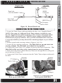
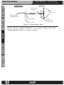
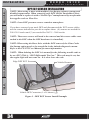
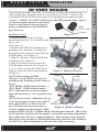
1
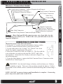
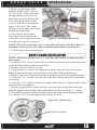
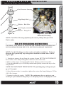
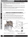
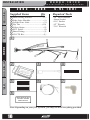
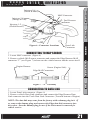
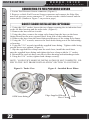
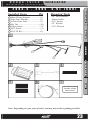
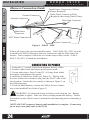
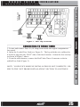
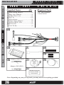
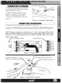
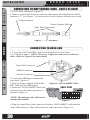
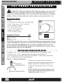
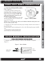
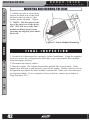
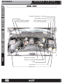
Dodge
Juice
installation Instructions
**read important safety information in this manual**
D o d g e
TABLE OF CONTENTS
I n s t a l l a t i o n
J u i c e
I n s t r u c t i o n s
TABLE OF CONTENTS
Table Of Contents
INTRODUCTION ........................................ 4
PRODUCT REGISTRATION ............................................. 4
IMPORTANT NOTES ...................................................... 5
ABOUT THE JUICE ....................................................... 6
INTRODUCTION
INSTALLATION .......................................... 8
1998.5 - 2002
5.9L (24V) .......................................... 8
INSTALLATION
CONNECTING TO CONSTANT POWER ..............................
CONNECTING TO GROUND ...........................................
CONNECTING TO KEY-ON POWER ..................................
CONNECTING TO MAP SENSOR .....................................
CONNECTING TO DATA LINK .........................................
CONNECTING TO INJECTION PUMP................................
BOOST ELBOW INSTALLATION ......................................
“LIFT PUMP” FUEL PRESSURE SENSOR INSTALL ............
FUEL SYSTEM BLEEDING INSTRUCTIONS .......................
CONNECTING TO TRANSMISSION (AUTOMATIC) ...............
CONNECTING TO TRANSMISSION (STANDARD) ...............
2003 - 2004
9
10
10
11
11
12
13
14
15
16
17
5.9L (CR) ............................................ 18
OPERATING INSTRUCTIONS
CONNECTING TO POWER ..............................................
CONNECTING TO GROUND ...........................................
CONNECTING TO INJECTORS ........................................
CONNECTING TO MAP SENSOR .....................................
CONNECTING TO DATA LINK .........................................
CONNECTING TO FUEL PRESSURE SENSOR ...................
BOOST ELBOW INSTALLATION (OPTIONAL) .....................
19
20
20
21
21
22
22
2004.5 - 2005 5.9L (600) ......................................... 23
CONNECTING TO POWER .............................................. 24
CONNECTING TO TURBO TIMER ..................................... 25
APPENDIX
2006 - 2011
CONNECTING
CONNECTING
CONNECTING
CONNECTING
CONNECTING
CONNECTING
5.9L & 6.7L ......................................... 26
TO
TO
TO
TO
TO
TO
POWER ..............................................
GROUND ...........................................
INJECTORS ........................................
MAP SENSOR (2006 - 2007 5.9L ONLY)
DATA LINK .........................................
THE TURBO TIMER ..............................
27
29
29
30
30
31
2007.5-2011 6.7L (RACING) ..................................... 33
DPF EGT SENSOR INSTALLATION .................................. 34
EGR “SPOOFER” INSTALLATION ................................... 35
2
D o d g e
I n s t a l l a t i o n
J u i c e
I n s t r u c t i o n s
TABLE OF CONTENTS
TAPPING AND PROBE INSTALLATION............................. 36
CONNECTING THE PROBE TO JUICE .............................. 38
TABLE OF CONTENTS
EGT PROBE INSTALLATION.........................................36
JAB INSTALLATION ...................................................39
JUICE MODULE INSTALLATION ................................... 41
FINAL JUICE MODULE INSTALLATION ............................ 41
MOUNTING AND SECURING THE JUICE .......................... 42
FINAL INSPECTION ....................................................42
INTRODUCTION
1998.5 TO 2011 - JAB INSTALLATION ............................ 39
2006-2011 OBDII CONNECTION .................................... 41
OPERATING INSTRUCTIONS ..................... 43
USING THE JUICE ....................................................43
ENGINE COMPARTMENT(REFERENCE) .........................44
1998.5 - 2002 ............................................................ 44
2003-2005 ................................................................ 45
2006 - 2011 ............................................................... 46
INSTALLATION
APPENDIX .............................................. 44
OPERATING INSTRUCTIONS
APPENDIX
3
INTRODUCTION
TABLE OF CONTENTS
P R O D U C T
D o d g e
I n s t a l l a t i o n
J u i c e
I n s t r u c t i o n s
R E G I S T R AT I O N
PLEASE take the time to register your product on line at edgeproducts.com. Follow the instructions at link: http://www.edgeproducts.com/product_registration.php
BENEFITS OF PRODUCT REGISTRATION
INTRODUCTION
INSTALLATION
OPERATING INSTRUCTIONS
-Your Safety - Registering your product allows us to know exactly
which product you have and provide important product updates to
you that improve the quality and/or safety of the product.
-Enhanced Features - Almost all Edge products are easily updated
via the internet. We are constantly adding new features and improvements to our product that we know you will want to enjoy.
-Confirmation of Ownership - Provides a record in case of product loss, theft, or required warranty work. When you call us for
support our team will already have much of the information they
need to help you.
-Improved Product Development - Helps us better understand
you (our customer) and design products that meet your needs.
-Special Offers - Allows us to inform you about special offers on
accessories and/or new products that fit your vehicle and enhance
your driving experience.
APPENDIX
4
D o d g e
I n s t a l l a t i o n
J u i c e
I n s t r u c t i o n s
INTRODUCTION
N O T E S
TABLE OF CONTENTS
I M P O R TA N T
1. If you have used another tuner/programmer on
your truck, you will need to program your truck
back to stock before using the Attitude or Juice.
Failure to return to stock may result in PCM failure or engine
damage.
INTRODUCTION
2. Programming your vehicle may expose existing defects in your
vehicle’s PCM that could disable your vehicle. It is advised that
you do not program your vehicle in remote location in case of
vehicle failure.
OPERATING INSTRUCTIONS
APPENDIX
4. For specific information regarding horsepower, torque, and
other features available for this product:
(1) Go to www.edgeproducts.com
(2) Type the part number of your product in the “KEYWORD/
PART# SEARCH” and press enter.
(3) Click the link under “Description”
INSTALLATION
3. All Edge modules and programmers are built to operate with
OEM calibrations. When you take your vehicle to a service center
they may, by your request or otherwise, update your vehicle’s
calibrations. Therefore it is important that you return your vehicle
to stock before taking it in for service. Edge updates its active
products (i.e. those currently being manufactured) to work effectively with updated OEM calibrations. However, this process can
take some time as Edge is not always made aware of calibration
changes made by the OEM. In the case of discontinued products,
Edge cannot ensure that your unit will work effectively if you take
your vehicle to a dealership and you are given, by your request or
otherwise, a new calibration.
(4) Scroll down to the “DOWNLOAD VEHICLE SPECIFIC HORSEPOWER, TORQUE, AND FEATURES CHART” link and click on it.
(5) Find the information that is specific to your make and model.
5
D o d g e
INTRODUCTION
I n s t a l l a t i o n
TABLE OF CONTENTS
A B O U T
T H E
J u i c e
I n s t r u c t i o n s
J U I C E
Congratulations on purchasing the Edge Juice/Attitude system for
the Dodge Cummins Diesel®.
INTRODUCTION
The Juice/Attitude system features an intelligent module (Juice)
that acts as an add-on Engine Control Module (ECM) for the Cummins Diesel® Engine. This module is controlled and customized
in the cab of your truck by the Attitude monitor/controller.
INSTALLATION
OPERATING INSTRUCTIONS
This system offers many cutting-edge, additional features not
available with the factory setup. Since the Juice Module is an addon ECM, it uses data from your truck’s computer or engine control
module (ECM), and then enhances the factory settings to optimize
your truck’s performance. This product offers a wide variety of
amazing performance and safety features that can ensure you get
the driving experience you desire without damaging your truck.
Please take the time to thoroughly review all of the features and
product options outlined in this manual. Taking the time to understand how this product works and how to properly operate this
product will ensure that you have an extraordinary and safe driving
experience. If we can be of any assistance to help you get the most
from your product please call us at 888-360-3343. We are open
Monday through Friday from 8am to 5pm Mountain Time.
APPENDIX
6
D o d g e
I n s t a l l a t i o n
J u i c e
I n s t r u c t i o n s
INTRODUCTION
TABLE OF CONTENTS
IMPORTANT: Read all Safety, Warranty, and Installation Instructions in this manual and the CS/CTS User Guide before installing this product. Read through these instructions completely
so that you understand each step prior to installation.
INTRODUCTION
SAFETY TERMS
Throughout this User Guide (hereafter noted as User Manual or
Manual) you will see important messages regarding your safety or
the protection of your vehicle. These messages are designated by
the words WARNING or CAUTION.
OPERATING INSTRUCTIONS
CAUTION indicates a condition that could cause damage to your
vehicle. It is important to install and operate your EDGE product in conformance with instructions in this Manual. Caution
alerts you to particularly important things that will keep your
vehicle operating properly.
INSTALLATION
WARNING indicates a condition that may cause serious
injury or death to you, your passengers or others nearby. Pay
careful attention to these Warning messages, and always comply
with them. They could save a life.
APPENDIX
7
D o d g e
I N S TA L L AT I O N
I n s t a l l a t i o n
TABLE OF CONTENTS
1 9 9 8 . 5 Supplied Items
2 0 0 2
Qty
INTRODUCTION
INSTALLATION
1 Main Wiring Harness...................(1)
2 Edge Juice Module.......................(1)
3 Adapters.......................................(1)
4 Zip Ties ......................................(10)
5 Hose Clamp..................................(1)
6 Brass Fitting.................................(1)
7 Leaded Fuse Link.........................(2)
8 Velcro Strips..................................(2)
9 Fuel Pressure Sensor....................(1)
10 Temperature Sensor......................(1)
11 EGT Probe...................................(1)
12 Banjo Bolt...................................(1)
13 Washer.........................................(2)
14 CS/CTS Kit.................................(1)
J u i c e
I n s t r u c t i o n s
5 . 9 L ( 2 4 V )
Required Tools
-Knife
-2 to 3 ft of wire (fishing)
-Needle nose pliers
-Phillips screwdriver
-Flat tip screwdriver
-3/8” Drive Torque Wrench
-1/2” Wrench
-3/8” Drive Ratchet
-1/4” Socket
-5/16” Socket
-7/16” Deep Well Socket
-10mm Socket
-13mm Socket
-1/8” NPT Tap
-5/16” or 21/64” Drill Bit
1
OPERATING INSTRUCTIONS
2
3
2001-2002 (MAP)
4
2000 (Data Link)
5
APPENDIX
6
7
8
9
10
11
12
13
14
REFER TO QUICK
INSTALL GUIDE
FOR INSTALL
Note: Depending on your year of truck, you may not need everything provided.
8
D o d g e
I n s t a l l a t i o n
J u i c e
I n s t r u c t i o n s
I N S TA L L AT I O N
Harness Connection Guide
OPERATING INSTRUCTIONS
CONNECTING TO CONSTANT POWER
INSTALLATION
Figure 1 - (Data Link and MAP connectors may vary from this view depending on your vehicle year. If this is the case, you will need to use the
supplied adapters.)
INTRODUCTION
Attitude Connector
Constant Power Connector Red (Required for Turbo Timer
Data Link Connector
Install, otherwise Optional).
Transmission Temp Sensor Connector(Purple/White)
TABLE OF CONTENTS
Key-On Power Connector - Yellow (Required at all times)
Injection Pump Connector
Fuel Pressure Connector
Ground Connector (Black)
EGT Probe Connector
MAP Connectors
Main Juice
Connector
(Required for proper Turbo-Timer functionality)
APPENDIX
1. Using the ½” wrench, loosen both negative battery cables.
2. Remove cables from the battery posts and set aside.
3. Locate and remove the 10 Amp “A/C Clutch” fuse from
inside the engine compartment fuse panel.
4. Insert the Leaded Fuse link (see Figure 2). The leg with the
wire soldered to it needs to plug into the “HOT” side of the
fuse location. Orient the fuse exactly as shown in Figure 3 on
Figure
i
2
the following page.
5. From the main harness, connect the Red Constant Power Connector to the
installed Fuse Link (Figure 3)
WARNING An electrical charge or battery acid can burn you. Battery
gas can explode or ignite. Take care when working around the battery. Follow
instructions in the vehicle owner’s manual for disconnecting and reconnecting a
battery.
NOTE: DO NOT reconnect battery until installation is complete. Connecting
power may cause fault code in the ECM.
9
D o d g e
I N S TA L L AT I O N
I n s t r u c t i o n s
TABLE OF CONTENTS
To Fire-wall
I n s t a l l a t i o n
J u i c e
Figure 3
Fuse Diagram (Engine
Compartment)
INTRODUCTION
CONNECTING TO GROUND
1. Connect the Ground Connector to the NEGATIVE side of the battery.
CONNECTING TO KEY-ON POWER
INSTALLATION
OPERATING INSTRUCTIONS
1. Cut a 1/2” slit in the fire wall grommet.
NOTE: Automatics - easy access is the clutch hole grommet located to the left
of the fire wall brake hole. Manuals or Automatics- Use the large vehicle wiring harness grommet on the fire wall.
2. Route the Yellow Key-On Connection from the engine compartment to inside
the cab through the cut hole from step 1.
3. Locate and remove Fuse 9 (10 Amp) from inside the driver side fuse panel.
4. Insert the Leaded Fuse link (see Figure 2). The leg with the wire soldered to
it needs to plug into the “HOT” side of the fuse location. Orient the fuse exactly
as shown in Figure 4 below.
5. Connect the Yellow Key-On (routed in step 2) to the installed Fuse Link.
FUSE 9
APPENDIX
Fire wall
Grommet
Routed Cable
Figure 4 - Driver Side Fuse Panel
10
D o d g e
I n s t a l l a t i o n
J u i c e
I n s t r u c t i o n s
I N S TA L L AT I O N
CONNECTING TO MAP SENSOR
NOTE: The MAP sensor ‘T’ shown in Figure 6 is for the 1998.5 - 2000 Juice.
The 2001 and 2002 harnesses have different sensor connectors, but in the
same location. Refer to Figure 5 for truck connector locations.
TABLE OF CONTENTS
1. Disconnect the stock wiring harness from the boost sensor located at the rear
of the fuel filter housing (Near the top of and on the engine block). See Figure 5
2. Plug the Edge harness MAP connectors in between the truck MAP sensor and
the truck MAP sensor cable. (Figure 6)
INTRODUCTION
98.5-02 MAP Sensor
00-02 Data Link
98.5-99 Data Link
INSTALLATION
Truck Harness Sensor (Engine Side)
g MAP Connectors
Edge
Figure 6 - “T” Assembly
CONNECTING TO DATA LINK
NOTE: On some 2001 trucks the Data Link connector can be located on the
driver’s side of the engine in the wiring harness near the power steering pump.
2. Replace the protective plug on the truck Data Link with the Juice harness
Data Link Connector. (Refer to Figure 5 above)
11
APPENDIX
1. Locate the Data link connectors:
• 1998.5 - 1999: The triangle shaped connector is located on the driver’s side
of the engine in the wiring harness near the power steering pump.
• 2000 - 2002: The three pronged flat connector is located on top of the fuel
lift pump that is located on the driver’s side of the engine directly below the
MAP sensor. (The 2000 must use the 2000 Data link Adapter.)
OPERATING INSTRUCTIONS
Figure 5 - Connector
Locations
D o d g e
I N S TA L L AT I O N
I n s t a l l a t i o n
J u i c e
I n s t r u c t i o n s
CONNECTING TO INJECTION PUMP
TABLE OF CONTENTS
NOTE: Although attaching the Juice cable to the VP 44 pump control wire
is optional; not tapping into the VP 44 pump prevents the Juice module from
increasing the output of the Cummins engine to it’s full potential and will
result in limited horsepower and torque gains. In order to control the pump
more directly, the Juice module needs to be electrically attached to the VP 44
pump. In order to attach the module to the VP 44 pump, the control wire must
be pierced with the Posi-Tap® wire provided on the Juice harness.
INTRODUCTION
The following figures 7-9 show how to connect the Juice to the Bosch VP 44
high pressure pump and how and where to attach the Posi-Tap® connection.
Figure 8 is a Bosch VP 44 pump that has been removed from a truck. This is
the same pump used on Cummins engines for model year trucks from 1998.5
to 2002.
INSTALLATION
OPERATING INSTRUCTIONS
1. Unbolt and remove the casting that
Remove
attaches to the Throttle Position Sensor (TPS) housing to expose the fuel
pump and the associated control wire.
(Figure 7)
2. Using a sharp knife or razor, carefully slice back the insulation that covers both pump wires contained in wire
bundle number one (see figure 8).
3. Locate the TOP injection pump wire
identified in Figures 8 & 9.
Figure 7 - Throttle Position Housing
NOTE: This will be the wire on the top, closest to the engine block when the
pump is installed on the truck.
4. Unscrew the “top” of the Posi-Tap® and place the wire to be tapped in the
slot provided in the cap.
Wire Bundle 2 (Do Not Modify)
APPENDIX
(Modify this wire)
Wire Bundle 1
Figure 8 - VP44 Fuel Pump
12
D o d g e
I n s t a l l a t i o n
J u i c e
I n s t r u c t i o n s
Cap
TABLE OF CONTENTS
Body
INTRODUCTION
5. Place a single drop of RTV
Silicone Sealer in the CAP of
the Posi-Tap®. There should be
enough silicone sealer so that
when the cap is installed on the
Posi-Tap® body some of the
sealer is pushed out around the
edges of the wire. The sealer
provides a water tight seal in and
around the connection.
6. Pre-twist the body of the
Posi-Tap® counter clockwise
with about seven full turns before
twisting on to cap. (See figure 9)
I N S TA L L AT I O N
Figure 9 - PosiTap® Pre-Twist
BOOST ELBOW INSTALLATION
OEM brass fitting
13
APPENDIX
Figure 10 - Turbo View
OPERATING INSTRUCTIONS
NOTE: On some vehicles, there is a solid line and cannot be replaced with a
brass elbow.
1. Using the 5/16” socket, loosen the two clamps securing the air induction hose
to the air filter housing and the turbo inlet.
2. Remove the hose and set it aside.
3. Using the pliers, remove the crimp style clamp from the hose on the brass
fitting located on the now exposed lower front side of the turbocharger.
4. Remove the hose from the brass fitting and dispose of the crimp style clamp.
5. Using the 7/16” wrench, unscrew the stock brass fitting out of the turbocharger housing.
6. Using the 7/16” wrench, install the supplied brass fitting. Tighten while being
careful not to over-tighten.
7. Slip the supplied hose clamp onto the stock hose then install the stock hose
onto the supplied brass fitting and tighten the hose clamp with the ¼” socket.
8. Reinstall the stock air hose onto the air filter housing and turbocharger inlet.
9. Using the 5/16” socket, tighten both clamps securely.
INSTALLATION
NOTE: This will pre-load the wire so that when the body of the Posi-Tap® is
installed on the cap, the wire will not remain twisted in the wire harness.
7. Twist harness onto cap until tight.
I N S TA L L AT I O N
D o d g e
I n s t a l l a t i o n
J u i c e
I n s t r u c t i o n s
TABLE OF CONTENTS
Edge Supplied Elbow
Hose Clamp
Hose
Figure 11 - Installed Boost Elbow
INTRODUCTION
“LIFT PUMP” FUEL PRESSURE SENSOR INSTALL
INSTALLATION
CAUTION: If you lack experience or tools
to bleed the fuel system take the truck to an
experienced mechanic for installation of the
fuel pressure sensor!
CAUTION: The fuel that is pumped to the
injectors also acts as a lubricant for the Bosch
VP-44 high pressure pump. A loss of fuel pressure to the high pressure pump may result in
permanent damage to the high pressure pump.
OPERATING INSTRUCTIONS
APPENDIX
1. Thread fuel pressure sensor into the supplied banjo
bolt.
2. Remove the stock banjo
bolt from the injector pump
supply line located on the
VP44 with the pre-installed
neoprene washer and fuel
pressure sensor. (Figure 14)
3. Tighten bolt to the appropriate torque specifications
(18 ft-lbs)
Figure 12 - VP44
Figure 13
CAUTION: When the Fuel Supply Line is removed, fuel can drain out of the
VP 44 pump, and air can enter the line and/or pump. In order to minimize
the amount of air that is let into the fuel system, pre-install the fuel pressure
sensor onto the supplied banjo bolt before removing the stock banjo bolt from
the pump. Tighten the sensor into the banjo bolt until it is snug.
14
D o d g e
I n s t a l l a t i o n
J u i c e
I n s t r u c t i o n s
I N S TA L L AT I O N
TABLE OF CONTENTS
Fuel Pressure Sensor
INTRODUCTION
Edge Banjo Bolt
Washer - Bolt Side
Fuel Supply
Line
Washer - Pump Side
INSTALLATION
Figure 14
Figure 15- Fuel Filter
Method (1999 Only)
NOTE: Fuel Filter Housing (Optional placement of Banjo bolt for 1999
Trucks only).
CAUTION: IT IS CRITICAL THAT THE AIR INTRODUCED INTO THE FUEL
LINE BE REMOVED FOR THE FUEL SYSTEM TO OPERATE PROPERLY.
NOTE: Use this bleeding procedure at the end of the installation. Trying to
bleed the fuel system half way through the installation could cause a check
engine light.
NOTE: DO NOT START THE ENGINE! The fuel lift pump will operate for
up to 25 seconds.
4. Once this procedure is complete, tighten the return line banjo fitting to 24 Nm
(18 ft-lbs.) torque.
5. Attempt to start the engine. NOTE: The engine may be very noisy or run
erratic for a few minutes. Keep an eye on the fuel pressure as displayed on the
15
APPENDIX
1. In order to remove the air from the system, loosen BUT DO NOT REMOVE
the overflow valve banjo fitting that connects to the return line.
2. Place a shop rag or towel around the banjo fitting to catch excess fuel.
3. Turn the ignition key to CRANK position and quickly release the key to the
ON position.
OPERATING INSTRUCTIONS
FUEL SYSTEM BLEEDING INSTRUCTIONS
I N S TA L L AT I O N
D o d g e
I n s t a l l a t i o n
J u i c e
I n s t r u c t i o n s
TABLE OF CONTENTS
Attitude. If the pressure drops below 4 psi, or the engine quits running, rebleed the fuel system. If the engine still does not start, remove and check the
fuel filter. If the filter is dirty or damaged, replace the filter.
CAUTION:
•Do not engage the starter motor for more than 30 seconds – Allow two minutes between cranking intervals.
•Although it is rare, on occasions the LIFT pump may fail to prime after the
banjo bolt has been replaced signifying a possibility of a worn pump. In this
rare instance the LIFT pump should be replaced.
INTRODUCTION
6. Reinstall the throttle bracket onto the fuel injection pump using the three
bolts. Torque these bolt to 18 ft-lbs using a torque wrench and 13mm socket.
CONNECTING TO TRANSMISSION (AUTOMATIC)
INSTALLATION
OPERATING INSTRUCTIONS
1. Unbolt the stock plug from passenger side rear of the transmission using a
7/16 inch (11mm) wrench (see Figure 17).
NOTE: A small amount of transmission fluid will leak from the outlet.
2. Apply Teflon tape to the threads of the transmission temperature sensor.
3. Using a ½ inch wrench, thread the Edge supplied transmission oil
temp sensor (see parts list) and connect the cable using the supplied nut.
4. From the top of the engine, route the transmission temperature sensor along
the factory wiring harness and over the top of the transmission and secure with
supplied wire ties.
Nut
Lock
Washer
Edge
Cable
APPENDIX
Washer
Fiber Woven
Washer
Sensor
Truck Front
(Passenger side)
Figure 16 - Automatic Transmission
16
Insert this
end into
transmission
Figure 17- Sensor Assembly
Refers to Fig 16 & 18
D o d g e
I n s t a l l a t i o n
J u i c e
I n s t r u c t i o n s
I N S TA L L AT I O N
CONNECTING TO TRANSMISSION (STANDARD)
Transmission
OPERATING INSTRUCTIONS
PTO Cover Plate
INSTALLATION
Bell Housing
INTRODUCTION
NOTE: YOUR JUICE MODULE INSTALLATION IS NOT COMPLETE. REFER TO THE “EGT PROBE INSTALLATION” SECTION TO CONTINUE.
TABLE OF CONTENTS
NOTE: When the Power Take-Off (PTO) plate is removed ALL of the gear
lube from the transmission will drain out – Ensure that you have the CORRECT replacement oil prior to removing the PTO plate. See the Dodge service
manual for replacement gear lube type.
1. Using a 14 mm wrench, remove the lowest bolt on the PTO cover plate and
drain the transmission fluid.
2. Unbolt the remaining five bolts to the PTO cover plate and remove it completely.
3. Using a 5/ 16” or 21/64” drill bit, drill a hole in the PTO cover plate in the
location shown in figure 18.
4. Using a 1/8” NPT tap, thread the hole in the PTO cover plate.
5. Apply Teflon tape or pipe thread sealant to the transmission temperature sensor and thread it into the PTO cover plate.
6. Clean the surface of the PTO cover plate and transmission . Apply an automotive gasket silicone to the plate surface that will come in contact with the
transmission.
7. Re-attach the plate cover to the transmission and connect the sensor cable to
the sensor.
8. Refill the transmission with fluid.
APPENDIX
Truck Front
(Driver Side)
Figure 18 - Manual Transmission (Driver Side)
17
D o d g e
I N S TA L L AT I O N
TABLE OF CONTENTS
2 0 0 3
I n s t a l l a t i o n
-
2 0 0 4
Supplied Items
INTRODUCTION
1
2
3
4
5
6
7
8
Qty
Main Wiring Harness.....................(1)
Edge Juice Module.........................(1)
Leaded Fuse Link...........................(1)
Zip Ties .......................................(10)
Velcro Strips...................................(2)
EGT Probe......................................(1)
Brass Fitting...................................(1)
CS/CTS Kit....................................(1)
5 . 9 L
J u i c e
I n s t r u c t i o n s
( C R )
Required Tools
-3/8” Drive Ratchet
-10mm Socket
-5/16” Socket
-1/2” Wrench
-7/16” Wrench
1
INSTALLATION
OPERATING INSTRUCTIONS
3
4
5
6
7
APPENDIX
2
8
REFER TO QUICK
INSTALL GUIDE
FOR INSTALL
Note: Depending on your year of truck, you may not need everything provided.
18
D o d g e
I n s t a l l a t i o n
J u i c e
I n s t r u c t i o n s
I N S TA L L AT I O N
Harness Connection Guide
TABLE OF CONTENTS
Ground Connector
Power Connector
Fuel Pressure Connectors
Main Juice
Connector
MAP Connectors
INJ 5&
3&
IN
J
IN
4
2
&
J1
INTRODUCTION
Attitude Connection
EGT Probe Connection
6
Data Link Connector
Injector Connectors
INSTALLATION
Figure 1 - Main Wiring Harness
CONNECTING TO POWER
OPERATING INSTRUCTIONS
WARNING An electrical charge or battery acid can burn you. Battery
gas can explode or ignite. Take care when working around the battery. Follow
instructions in the vehicle owner’s manual for disconnecting and reconnecting a
battery.
NOTE: DO NOT reconnect battery until installation is complete. Connecting
power may cause fault code in the ECM.
19
APPENDIX
1. Using the ½” wrench, loosen both negative battery cables.
2. Remove cables from the battery posts and set aside.
3. Locate and remove Fuse 50 (10 Amp) from inside the engine
compartment fuse panel.
4. Insert the Leaded Fuse Link (see Figure 2). The leg with
the wire soldered to it needs to plug into the “HOT” side of the
fuse location. Orient the fuse exactly as shown in Figure 3 on
Figure
i
2
the following page.
5. From the main harness, connect the Red Power Connector to the installed
Fuse Link (Figure 3)
D o d g e
I N S TA L L AT I O N
I n s t a l l a t i o n
J u i c e
I n s t r u c t i o n s
TABLE OF CONTENTS
To Fire-wall
Figure 3 - Fuse Box
INTRODUCTION
Fuse 50
INSTALLATION
CONNECTING TO GROUND
Ground Connector
OPERATING INSTRUCTIONS
1. Connect the ground to the vehicle by
removing the 10mm bolt from the driver
side fender, above the battery.
2. Add the black ground connector with
the round terminal to the wires already
on the bolt.
3. Replace and tighten the bolt. (See
Figure 4)
Figure 4 - Ground Connections
CONNECTING TO INJECTORS
APPENDIX
1. Disconnect all 3 stock injector connectors by squeezing the tab on the top of
each connector. (Figure 6 for locations)
2. Gently insert the Juice ‘T’ Injector Connectors between the stock connectors,
and lock in place. (Figure 5) NOTE: Match Edge Harness connectors to the
proper injector set according to the wire colors described in Figure 6.
CAUTION: When inserting connector bodies. If the connector does not slide
smoothly, remove the connector, inspect the pins, and retry installation.
Truck
Injector
Edge Injector Connectors
Figure 5 - “T” Assembly
20
Truck
Harness
D o d g e
I n s t a l l a t i o n
J u i c e
I n s t r u c t i o n s
I N S TA L L AT I O N
TABLE OF CONTENTS
Injectors 5-6
(Green & Blue)
MAP Connector
Injectors 3-4
(Orange & Tan)
Fuel Pressure
Sensor
Injectors 1-2
(Red & Brown)
INTRODUCTION
Data Link
Connector
INSTALLATION
Figure 6 - Connector Locations
CONNECTING TO MAP SENSOR
1. Locate MAP connector. (Figure 6)
Engine Harness
Sensor (Engine Side)
Edge MAP Connectors
OPERATING INSTRUCTIONS
2. Remove vehicle MAP sensor connector and connect the Edge Harness MAP
connector “T” (see Figure 7) in between the vehicle harness and the sensor itself.
APPENDIX
Figure 7 - “T” Assembly
CONNECTING TO DATA LINK
1. Locate Data Link connector. (Figure 6)
2. Remove vehicle Data Link connector and connect the Edge Harness Data
Link connector into the Truck Data Link Connector. (Towards bottom of Engine)
NOTE: The data link may come from the factory with a dummy plug in it. If
so, remove the dummy plug, and connect the Edge data link connector into
the socket. Save the dummy plug for use if the Juice must be removed for
vehicle service.
21
I N S TA L L AT I O N
D o d g e
I n s t a l l a t i o n
J u i c e
I n s t r u c t i o n s
CONNECTING TO FUEL PRESSURE SENSOR
TABLE OF CONTENTS
1. Locate Fuel Pressure Sensor connector. (Figure 6)
2. Remove vehicle Fuel Pressure Sensor connector and connect the Edge Harness Fuel pressure sensor connector “T” in between the vehicle harness and the
sensor itself. (Similar to Figure 7 on previous page)
BOOST ELBOW INSTALLATION (OPTIONAL)
INTRODUCTION
INSTALLATION
1. Using the 5/16” socket, loosen the two clamps securing the air induction hose
to the air filter housing and the turbo inlet. (Figure 8)
2. Remove the hose and set it aside.
3. Using the pliers, remove the crimp style clamp from the hose on the brass
fitting located on the now exposed lower front side of the turbocharger.
4. Remove the hose from the brass fitting and dispose of the crimp style clamp.
5. Using the 7/16” wrench, unscrew the stock brass fitting out of the turbocharger housing.
6. Using the 7/16” wrench, install the supplied brass fitting. Tighten while being
careful not to over-tighten. (Figure 9)
7. Slip the supplied hose clamp onto the stock hose, install the stock hose
onto the supplied brass fitting and tighten the hose clamp with the ¼” socket.
8. Reinstall the stock air hose onto the air filter housing and turbocharger inlet.
9. Using the 5/16” socket, tighten both clamps securely.
OPERATING INSTRUCTIONS
NOTE: YOUR JUICE MODULE INSTALLATION IS NOT COMPLETE. REFER TO THE “EGT PROBE INSTALLATION” SECTION TO CONTINUE.
Figure 8 - Turbo View
Figure 9 - Installed Boost Elbow
APPENDIX
OEM brass fitting
22
Edge Supplied Elbow
Hose Clamp
Hose
D o d g e
I n s t a l l a t i o n
J u i c e
I n s t r u c t i o n s
-
2 0 0 5
Supplied Items
Main Wiring Harness..................(1)
Edge Juice Module......................(1)
Leaded Fuse Link........................(3)
Zip Ties ......................................(10)
Velcro Strips.................................(2)
EGT Probe....................................(1)
CS/CTS Kit..................................(1)
( 6 0 0 )
Required Tools
-3/8” Drive Ratchet
-10mm Socket
-5/16” Socket
-1/2” Wrench
-7/16” Wrench
INTRODUCTION
1
2
3
4
5
6
7
Qty
5 . 9 L
TABLE OF CONTENTS
2 0 0 4 . 5
I N S TA L L AT I O N
1
INSTALLATION
4
5
6
7
APPENDIX
3
OPERATING INSTRUCTIONS
2
REFER TO QUICK
INSTALL GUIDE
FOR INSTALL
Note: Depending on your year of truck, you may not need everything provided.
23
D o d g e
I N S TA L L AT I O N
I n s t a l l a t i o n
Harness Connection Guide
Attitude Connector
6
Data Link Connector
4
IN
INJ 5&
2
&
J1
3&
INTRODUCTION
Main Juice
Connector
I n s t r u c t i o n s
Fused Power Connectors (Yellow)
(Always Required)
Turbo Timer Connector (Red)
(Required when using Turbo-Timer)
EGT Probe Connectors
IN
J
TABLE OF CONTENTS
Ground Connector
J u i c e
MAP Connectors
Injector Connectors
Figure 1 - 2004.5 - 2005
INSTALLATION
Follow all steps in the previous install section: “2003-2004 5.9L (CR)” in order
to install your MAP Connectors, Injector Connectors, and the Data Link Connectors. Once complete, follow the rest of the steps in this section: “2004.5 2005 5.9L (600)” to finish the installation.
OPERATING INSTRUCTIONS
CONNECTING TO POWER
APPENDIX
1. Using the ½” wrench, loosen both negative battery cables.
2. Remove cables from the battery posts and set aside.
3. Locate and remove Fuses 28 and 35 (10 Amp) from inside
the engine compartment fuse panel.
4. Insert the Leaded Fuse Links (see Figure 2). The leg with
the wire soldered to it needs to plug into the “HOT” side of the
fuse location. Orient the fuse exactly as shown in Figure 3 on
the following page.
5. From the main harness, connect the Yellow Power Connectors to the installed Fuse Links (Figure 3)
Figure
i
2
WARNING An electrical charge or battery acid can burn you. Battery
gas can explode or ignite. Take care when working around the battery. Follow
instructions in the vehicle owner’s manual for disconnecting and reconnecting a
battery.
NOTE: DO NOT reconnect battery until installation is complete. Connecting
power may cause fault code in the ECM.
24
D o d g e
I n s t r u c t i o n s
I N S TA L L AT I O N
TABLE OF CONTENTS
To Fire-wall
I n s t a l l a t i o n
J u i c e
INTRODUCTION
CONNECTING TO TURBO TIMER
NOTE: YOUR JUICE MODULE INSTALLATION IS NOT COMPLETE. REFER TO THE “EGT PROBE INSTALLATION” SECTION TO CONTINUE.
OPERATING INSTRUCTIONS
1. Locate and remove Fuse 16 (10 Amp) from inside the engine compartment
fuse panel.
4. Insert the Leaded Fuse Link (see Figure 2). The leg with the wire soldered to
it needs to plug into the “HOT” side of the fuse location. Orient the fuse exactly
as shown in Figure 3 above.
5. From the main harness, connect the Red Turbo Timer Connector to the installed Fuse Link (Figure 3)
INSTALLATION
Figure 3 - Fuse Tap Locations
APPENDIX
25
D o d g e
I N S TA L L AT I O N
TABLE OF CONTENTS
2 0 0 6
I n s t a l l a t i o n
-
2 0 1 1
Supplied Items
INTRODUCTION
1
2
3
4
5
6
7
8
9
5 . 9 L
Qty
Main Wiring Harness......................(1)
Edge Juice Module.........................(1)
Leaded Fuse Link...........................(1)
Zip Ties ........................................(10)
Velcro Strips...................................(2)
Turbo Timer Adapters.....................(2)
DATA/OBDII Cable.......................(1)
EGT Probe......................................(1)
CS/CTS Kit.....................................(1)
J u i c e
I n s t r u c t i o n s
&
6 . 7 L
Required Tools
-3/8” Drive Ratchet
-10mm Socket
1
INSTALLATION
OPERATING INSTRUCTIONS
2
3
4
5
APPENDIX
6
Adapter (2006-2009)
7
8
Adapter (2010-2011)
9
REFER TO QUICK
INSTALL GUIDE
FOR INSTALL
Note: Depending on your year of truck, you may not need everything provided.
26
D o d g e
I n s t a l l a t i o n
J u i c e
I n s t r u c t i o n s
I N S TA L L AT I O N
Harness Connection Guide
TABLE OF CONTENTS
Turbo-Timer Connector
Attitude Connector
EGT Probe Connectors
MAP Sensor Connectors
(2006-2007 5.9L Trucks Only)
Main Juice
Connector
INTRODUCTION
INJ 1-3
INJ 4-6
INSTALLATION
Data Link Connector
Power Connector
Injector Connectors
Ground Connector
Figure 1
OPERATING INSTRUCTIONS
CONNECTING TO POWER
APPENDIX
1. Using the ½” wrench, loosen both negative battery cables.
2. Remove cables from the battery posts and set aside.
3. Locate and remove the following fuses:
06-09 Trucks - Fuse 28
2010 Trucks - Fuse M52
2011 Trucks - Fuse M33
4. Insert the Leaded Fuse Links (see Figure 2). The leg with
Figure 2
the wire soldered to it needs to plug into the “HOT” side of
the fuse location. Orient the fuse exactly as shown in Figures
3A,3B, and 3C on the following page.
5. From the main harness, connect the Red Power Connector to the installed
Fuse Link (Figure 3)
WARNING An electrical charge or battery acid can burn you. Battery
gas can explode or ignite. Take care when working around the battery. Follow
instructions in the vehicle owner’s manual for disconnecting and reconnecting a
battery.
NOTE: DO NOT reconnect battery until installation is complete. Connecting
power may cause fault code in the ECM.
27
D o d g e
I N S TA L L AT I O N
I n s t r u c t i o n s
TABLE OF CONTENTS
To Fire-wall
I n s t a l l a t i o n
J u i c e
Fuse 28
INTRODUCTION
INSTALLATION
Fuse M52
To Fire-wall
Figure 3A - 2006-2009 Fuse Box
Use Rubber Seal for wire exit
OPERATING INSTRUCTIONS
Figure 3B - 2010 Fuse Box
Route wire as shown.
NOTE: Route the wire
along lid feature as
shown. This will reduce
the chance of the wire
being crushed when the
lid is closed.
APPENDIX
To Fire-wall
Fuse M33
Figure 3C - 2011 Fuse Box
28
D o d g e
I n s t a l l a t i o n
J u i c e
I n s t r u c t i o n s
CONNECTING TO GROUND
I N S TA L L AT I O N
Ground Connector
TABLE OF CONTENTS
1. Connect the ground to the vehicle
by removing the 10mm bolt from the
fender, above the battery.
2. Add the black ground wire (see
Figure 1) with the round terminal
to the wires already on the bolt.
3. Replace and tighten the bolt. (See
Figure 4)
CONNECTING TO INJECTORS
1. Locate the two stock injector connectors. (Figure 6)
2. Remove vehicle Injector Connectors and connect the Edge Harness Injector
connector “T” in between the vehicle harness and the sensor itself. (Figure 5)
OPERATING INSTRUCTIONS
Edge Inj Connectors
Figure 5 - Injectors
Injector Connector (4-6)
(blu/wht, grn/wht, tan/wht)
MAP Connector (06-07)
Figure 6 - C
Connector
onnector Locations
29
APPENDIX
Injector Connector (1-3)
(Org/wht, red/wht, brn/wht)
INSTALLATION
NOTE: Injector Connectors with injectors 1, 2, & 3 has Orange/White, Red/
White and Brown/White wires and a shorter cable length. The connector for
injectors 4, 5, & 6 has Blue/White, Green/White, and Tan/White wires and a
longer cable length.
Injector (Engine Side)
Engine Harness
INTRODUCTION
Figure 4 - Ground Connections
D o d g e
I N S TA L L AT I O N
I n s t a l l a t i o n
J u i c e
I n s t r u c t i o n s
CONNECTING TO MAP SENSOR (2006 - 2007 5.9L ONLY)
TABLE OF CONTENTS
1. Locate MAP connector. (Figure 6)
2. Remove vehicle MAP sensor connector and connect the Edge Harness MAP
connector “T” (see Figure 7) in between the vehicle harness and the sensor itself.
Engine Harness
Sensor (Engine Side)
Edge MAP Connectors
INTRODUCTION
Figure 7 - “T” Assembly
INSTALLATION
CONNECTING TO DATA LINK
1. Locate the “DATA/OBDII” cable provided in the box from Edge.
(see “Supplied Items”) NOTE: There are 3 different connectors on this one
cable. Refer to Figure 8 for more detail.
OPERATING INSTRUCTIONS
Data Link Connector
OBDII Connector
Attitude Connector
APPENDIX
2. Locate the OBDII port underneath
your dash. (Figure 9)
3. Plug the Edge supplied “DATA/OBDII” cable into the OBDII port.
4. Route the “DATA/OBDII” Data Link
Connector out the rubber grommet as
shown in Figure 10.
NOTE: The Attitude cable will later be
routed and installed.
Figure 8 - DATA/OBDII Cable
OBDII PORT
Figure 9
5. Plug the routed Data Link connector from the “DATA/OBDII” cable into the
“Edge Main Harness” Data Link connector under the hood. (Figure 10)
30
D o d g e
I n s t a l l a t i o n
J u i c e
I n s t r u c t i o n s
I N S TA L L AT I O N
Data Link
(“DATA/OBDII” Cable)
OBDII
Connector
Data Link
(Main Harness)
OBDII Port
INTRODUCTION
Cab Side
Attitude
Connector
TABLE OF CONTENTS
Engine Side
Grommet
Fire Wall
Figure 10 - Routed Data Link
CONNECTING TO THE TURBO TIMER
APPENDIX
Ignition
Module
Truck Cable
Truck
Cable
Figure 11 - Looking up from
brake pedal (2006-2009)
OPERATING INSTRUCTIONS
TT Adapter
Steering
Column
INSTALLATION
1. Locate the Turbo Timer cable provided in the box. (see “Supplied Items”)
NOTE: There may be 2 different Turbo Timer adapters included in your
kit. (See Supplied items at the beginning of this section to determine which
adapter will fit your model year.) Find the proper adapter and follow the
instructions to properly install it. Once you have determined the connector
is correctly installed, you may discard the remaining adapter as you will not
need it.
2. Remove panel under steering column. (Figures 11& 11A)
3. Locate the key position connectors. The 2006-2009 are up and inside the
steering column. The 2010-2011 are behind the key/ignition.
4. Connect the Turbo Timer (TT) adapter in between the truck connectors. The
2006-2009 will be an in-line cable coming from the steering column.
5. Route the Turbo Timer (Main Harness) connector through the fire wall grommet as shown in (Figure 12).
6. Connect the Turbo Timer connector into the Turbo Timer adapter underneath
the dash.
TT
Adapter
Figure 11A - Looking up from
brake pedal (2010-2011)
31
I N S TA L L AT I O N
D o d g e
I n s t a l l a t i o n
Engine Side
J u i c e
I n s t r u c t i o n s
Cab Side
TABLE OF CONTENTS
Turbo Timer
(Adapter)
Truck
Connectors
Turbo Timer
(Main Harness)
Gr
Grommet
INTRODUCTION
Fir
Fire wall
Edge
Turbo Timer
Connectors
Figure 12 - Routed Turbo Timer
NOTE: Your juice module installation is not complete. Refer to the “EGT
PROBE INSTALLATION” section to continue.
INSTALLATION
OPERATING INSTRUCTIONS
APPENDIX
32
D o d g e
I n s t a l l a t i o n
J u i c e
I n s t r u c t i o n s
6 . 7 L
( R A C I N G )
OPERATING INSTRUCTIONS
APPENDIX
33
INSTALLATION
NOTE: The installation for the EDGE RACING Juice harness is the same as
the 2006 - 2011 Installation instructions. Once the harness components are
installed, refer to the “DPF EGT SENSOR INSTALLATION” section.
INTRODUCTION
CAUTION: 2010 Dodge trucks that have been manufactured before March
2010 may generate engine fault codes. In order for the Race Juice to work
correctly with the DPF off, your truck may need to be updated. Only a Dealer
can update your truck’s computer so this is important to know before you
remove your DPF. To find out which software file your truck has, follow these
steps:
1. Have the Edge Racing Disclaimer (www.edgeproductsracing.com) signed
with the unlock code ready.
2. If you have already installed your juice module, to retrieve your vehicle’s
calibration I.D., skip to step 4.
3. Make the following connections to power up the device (NOTE: You will not
yet need to permanently install any of these connections):
Connection 1 - On the main juice harness, locate the single red wire and connect it to fuse M53 (fuse box under the hood). See Figure 3B on page 28 of
this manual. Use the supplied fuse taps.
Connection 2 - Connect the Juice Module to the Main Harness. See bottom of
page 41 of this manual.
Connection 3 - Connect the Green Juice Module Connector to the Green JAB
connector. See Figure 2 on page 39 of this manual.
Connection 4 - Make sure the EAS is assembled correctly (see Figure 2 page
39) and then plug the 6 pin connector into the back of the CS/CTS.
Connection 5 - Locate the OBDII connector under the dash, and plug in the
supplied OBDII cable. Route the opposite end to the data link connector on
the main harness, and plug them together. See Figures 8,9, and 10 on pages
30 & 31 of this manual.
Connection 6 - Plug the other end of the OBDII cable into the back of the CS/
CTS. See top of page 41 of this manual.
4. Turn the key to the on position and touch the screen (CTS) or press a button
(CS) and the device should power up. If not, check your connections.
5. Enter the MAIN MENU, then the HELP MENU, then choose the VEHICLE INFO option. If AU, AV, or AX is displayed at the end of the chain of
numbers, you will need to have your truck updated at the dealer. If you need
any help with this please contact tech support: 801-476-3343 or 888-360-3343
TABLE OF CONTENTS
2 0 0 7 . 5 - 2 0 1 1
I N S TA L L AT I O N
D o d g e
I N S TA L L AT I O N
I n s t a l l a t i o n
J u i c e
I n s t r u c t i o n s
DPF EGT SENSOR INSTALLATION
TABLE OF CONTENTS
NOTE: Most racing is done with modified, free-flowing exhaust systems and
disabled regeneration. When removing your DPF (Diesel Particulate Filter),
you will need to replace it with a “Delete Pipe” manufactured by an aftermarket supplier such as Flow-Pro.
NOTE: Leave DPF pressure sensors vented to atmosphere.
INTRODUCTION
If you have removed your stock DPF and disconnected the EGT sensor cables,
use the sensors included in your kit to replace them. (4) sensors are needed for
2010-2011 trucks and (3) are needed for 2007.5 - 2009 trucks.
NOTE: These new sensors will need to be removed and the sensor cables reattached to the DPF when the DPF hardware is reinstalled.)
INSTALLATION
NOTE: When using the Race Juice with the DPF removed, the Clear Codes
On Startup option needs to be turned On in the Attitude diagnostics menu.
Refer to the CS/CTS User Manual for more information.
NOTE: When deleting the DPF it is normal for the following trouble code to
be set: DTC P244A - “DPF Differential Too Low” This code may be set, but
the engine light will not come on. It is ok to leave the code.
OPERATING INSTRUCTIONS
Edge DPF EGT Sensor
Vehicle Harness
APPENDIX
Vehicle DPF Connector (1 of 4 shown)
Figure 1 - DPF EGT Sensor Install Example
34
D o d g e
I n s t a l l a t i o n
J u i c e
I n s t r u c t i o n s
I N S TA L L AT I O N
EGR “SPOOFER” INSTALLATION
INTRODUCTION
INSTALLATION
OPERATING INSTRUCTIONS
APPENDIX
35
TABLE OF CONTENTS
If you decide to disable the EGR, you will need to follow these instructions. In
order for the Edge Racing Product to work properly on 2010-11 trucks with
a disabled EGR, the EGR Sensor needs to be unplugged and replaced with a
p g the Male “Spoof“spoofer”. (NOTE: For 2007.5-2009 trucks, DO NOT plug
er” into the engine harness as described.
However, the female connector may be
Male
used to seal and protect the EGR Hous2010+ Only
ing Connector.
Female
Figure 2
Installation Steps:
1. Locate the EGR Sensor housing
Tab
underneath the hood. It is located on the EGR Housing
driver side.
(See Figure 3)
2. Remove the EGR Sensor Harness by
pushing in the connector’s locking tab,
then pulling the connector away from the
EGR housing. (See Figure 3)
3. Plug the “Spoofer” into the EGR Sensor harness (See Figure 4).
4. Plug the Female connector into the
EGR housing connector (See Figure 4).
EGR Sensor Harness
5. Use a zip tie to strap the EGR Sensor
Figure 3 - Remove Harness
Harness to the electrical conduit shown
in Figure 4.
Female
NOTE: When using the EGR
Male
“Spoofer” on the 2010-11 trucks, it is
normal for the following trouble codes to
be set:
-DTC P049D “EGR Control Position...”
-DTC P046C “EGR Position Sensor...”
These codes may be set, but the engine
light will not come on. It is ok to leave the
codes.
NOTE: If your truck’s calibration (see pg.
33 for instructions on how to get calibration) ends in BD on a 2010 or an AJ
Electrical Conduit
on a 2011 then you may experience a
Figure 4 - Remove Harness
“service exhaust system message” while
using the EGR “Spoofer” with the Intake Throttle plate removed. This condition is typically experienced if the engine is at normal operating temperatures
and is allowed to idle for a couple of minutes. This message can be ignored
and will go away by itself on 2010 models and will go away on 2011 models if
the DTCs are cleared manually or with the clear codes on startup.
D o d g e
I N S TA L L AT I O N
TABLE OF CONTENTS
E G T
I n s t a l l a t i o n
P R O B E
J u i c e
I n s t r u c t i o n s
I N S TA L L AT I O N
WARNING When installing the EGT Thermocouple, wear eye protection and protective clothing to protect from getting metal chips in your eyes.
Also, since exhaust manifolds can be very hot, allow the engine to cool before
drilling. When working under the vehicle, make sure the park brake is set.
Required Tools
INTRODUCTION
INSTALLATION
- Drill
- 1/8” drill bit or similar size (for pilot hole)
- 21/64” (best size) or 5/16” drill bit
- 9/16” wrench or socket
- 5/8” open end wrench
- 1/8”-27 NPT Thread Tap
- Phillips screwdriver
- 5/16” or 8mm wrench
Supplied Items
Qty
1
2
1 EGT Probe..................................(1)
2 Shrink Tube................................(2)
OPERATING INSTRUCTIONS
CAUTION: One effective way to avoid metal fragment contamination in your
engine manifold is to apply grease in the tip of the drill bit and threads of your
tap tool when drilling/tapping the hole in your manifold. Reduce pressure
on the drill when the drill breaks through the manifold wall to reduce risk of
pushing metal chips into the manifold.
TAPPING AND PROBE INSTALLATION
APPENDIX
1. Obtain a 1/8”-27 NPT Thread Tap available from your hardware store.
2. Drill a 21/64” (5/16” optional) hole through the manifold wall.
3. Use the pipe tap to cut the threads in accordance to the pipe tap manufacturer’s instructions and recommendations.
Figure 1 - Fitting Installation
4. Remove the fitting from the Thermocouple and install by tightening the tapered
Fitting
thread end into the manifold. (Figure 1)
Tapped Hole
5. Tighten the fitting so that it is securely
seated.
NOTE: Ideally the tip of the fitting would
be less than or flush with the inside of the
Exhaust M
Manifold Wall
exhaust flow path. (Figure 2)
36
D o d g e
I n s t a l l a t i o n
J u i c e
I n s t r u c t i o n s
I N S TA L L AT I O N
Figure 2 - Probe Insertion
Fitting
Flush
Probe
TABLE OF CONTENTS
Nut
6. Install the probe into the fitting,
and tighten the top nut of the fitting
just tight enough to keep the probe
firmly mounted. (Figure 2)
7. Make sure that the probe cable
is positioned to allow best path and
minimal bending for routing to the
fire wall.
INTRODUCTION
To Fire wall
Starting Position
90 Deg.
Correct
APPENDIX
CAUTION: Do not bend the probe after installed. If needed, loosen the
probe nut, adjust the probe, and re-tighten. Bending the probe tubing will
result in a faulty probe. (Figure 4)
OPERATING INSTRUCTIONS
Tightened Position
NOTE: The probe will move approximately 90 Deg. clockwise in
the direction the nut is tightened.
Before fully tightening the nut,
make sure the cable starts 90
Degrees from the final resting position. When tightened, the cable
will be correctly positioned.
INSTALLATION
Figure 3 - 90 Degree
Wrong
Figure 4 - DO NOT BEND
37
D o d g e
I N S TA L L AT I O N
I n s t a l l a t i o n
TABLE OF CONTENTS
1998.5 - 2002
J u i c e
I n s t r u c t i o n s
2003-2005
2006-2011
INTRODUCTION
EGT Location per year range
NOTE: All 3 views are looking
from the passenger side.
INSTALLATION
CONNECTING THE PROBE TO JUICE
1. Slide the shrink tube pieces over the two wires. Later you will slide them
over the bolted connections. (Figure 5)
OPERATING INSTRUCTIONS
Shrink Tube
Ring Terminals
Figure 5 - Shrink Tube
APPENDIX
2. Connect the (2) ring terminals to the
mating Juice harness terminals using the
supplied hardware. Yellow to Yellow. Red
to Red. (Figure 6)
3. Tighten the nuts so that each wire is in
line with its mating wire.
Nut
Bolt
Figure 6 - Hardware Install
4. Position the supplied shrink tube over the secure fasteners.
5. Center the connection within the shrink tube. Heat and shrink the tubing over
the connections. (Figure 7)
6. Secure the excess cable to the fire wall over hang with supplied zip ties.
Figure 7 - Shrink Tube Final
38
D o d g e
I n s t a l l a t i o n
J u i c e
I n s t r u c t i o n s
I N S T A L L AT I O N
NOTE: The CS/CTS will not function unless the JAB is properly
installed and plugged into both the Juice Module and Attitude
Monitor (CS/CTS).
1998.5 TO 2011 - JAB INSTALLATION
CS/CTS Connection
INTRODUCTION
1. Locate the green connector on
the Juice Harness and plug it into
the Green connector on the JAB.
INSTALLATION
2. Under the hood, connect the 3
EAS components to one another.
A “click” will be felt and heard
indicating that the connectors are
JAB Adapter “T”
correctly fastened.
Figure 1 - Juice Harness
TABLE OF CONTENTS
J A B
I N S TA L L AT I O N
End Cap
Figure 2 - JAB System
3. Route the CS/CTS Connector and cable through the fire wall
grommet. The JAB and Juice Module will remain under the hood.
(Figure 3)
APPENDIX
Engine Side
Cab Side
EAS Connector
OPERATING INSTRUCTIONS
Green Connectors
CS/CTS
Connector
Grommet
Fire Wall
Figure 3 - Fire Wall Routing
39
D o d g e
I N S TA L L AT I O N
I n s t a l l a t i o n
TABLE OF CONTENTS
INTRODUCTION
6. Route the cable from below the dash
up to the lower left corner of the driver
side windshield. (Figure 4)
7. If needed, remove side panels to help
see while routing.
8. Leave enough length between the dash
and the end of the CS/CTS connector for
easy CS/CTS install.
NOTE: For a clean look, the cable can
be hidden behind the dash plastic and
the door frame weather strip.
9. Using the supplied zip ties, fasten the
EAS connectors underneath the overhang
which runs across the top of the fire wall.
(Figure 5)
10. Keep the JAB assembly close to the
driver side.
J u i c e
I n s t r u c t i o n s
CS/CTS
Connector
Grommet
INSTALLATION
Figure 4 - In Cab Routing
OPERATING INSTRUCTIONS
Fire Wall
Overhang
Zip Ties
To CS/CTS
APPENDIX
JAB Assembly
To Juice
Figure 5 - Securing JAB (Looking from the front of the truck to back)
40
D o d g e
I n s t a l l a t i o n
J u i c e
I n s t r u c t i o n s
I N S TA L L AT I O N
J U I C E
M O D U L E
I N S TA L L AT I O N
FINAL JUICE MODULE INSTALLATION
APPENDIX
1. Plug the “Main Juice Connector” into the “Juice Module” receptacle.
(Figure 1)
Figure 1 - Juice Module
Main Juice
Harness
OPERATING INSTRUCTIONS
(a) Arkon Mount: Quick Install Guide
(b) POD Mount: POD Install Manual
INSTALLATION
4. Plug the CS/CTS Connector into the proper mating connector on the back of
the CS/CTS Unit,
5. Depending on your mounting style, refer to the following for proper installation:
INTRODUCTION
1. Locate the remaining Attitude ConnecCS/CTS Connector
tor on the already installed DATA/OBDII
Cable. (Figure 1)
2. Route the Attitude Connector and
remaining cable to the lower left corner
of the driver side windshield. (Similar to
Figure 4 on previous page) NOTE: This
cable should already be inside the cab
and underneath the dash.
3. Leave enough length between the dash
Figure 1 - DATA/OBDII
and the end of the CS/CTS connector for
easy CS/CTS install.
NOTE: For a clean look, the cable can be hidden behind the dash plastic and
the door frame weather strip.
TABLE OF CONTENTS
2006-2011 OBDII CONNECT I O N
Juice
Module
41
D o d g e
I N S TA L L AT I O N
I n s t a l l a t i o n
J u i c e
I n s t r u c t i o n s
MOUNTING AND SECURING THE JUICE
TABLE OF CONTENTS
INTRODUCTION
1. Attach one side of each velcro
strip to the back side of the Module and to the top side of a flat
surface under the hood. (Figure
2) NOTE: The best place is the
top of the fuse box on the driver
side. This will secure the Juice
module and help keep it away
from any moving/hot parts under
the hood.
Figure 2 - Juice Module Mounting
INSTALLATION
F I N A L
I N S P E C T I O N
OPERATING INSTRUCTIONS
1. Recheck all connections for a properly secure installation. Using the supplied
wire ties, secure the wiring harness and cable to prevent possible heat damage
from hot engine surfaces.
2. Reconnect the battery cables.
3. Start the engine. The engine should start and idle like a stock truck. If the
engine does not start or run properly, turn off the engine. Remove the keys from
the ignition, and check the Juice module connections. Make sure all connectors
are fastened tightly. If you continue to have problems, contact your dealer or
Edge Products, LLC.
APPENDIX
42
D o d g e
I n s t a l l a t i o n
J u i c e
I n s t r u c t i o n s
T H E
J U I C E
Refer to the CS/CTS User Manual for detailed descriptions on how
to operate the Attitude Monitor.
INTRODUCTION
EGT’s
EGT stands for exhaust gas temperature, and is the single most
important indicator of how a diesel engine is performing. Unlike
a gasoline motor, a diesel motor will continue to make power as
more fuel is added. As more fuel is added, the engine heat will
also increase. Please be aware of the limitations of a stock engine.
TABLE OF CONTENTS
U S I N G
O P E R AT I N G I N S T R U C T I O N S
INSTALLATION
OPERATING INSTRUCTIONS
APPENDIX
43
D o d g e
APPENDIX
I n s t a l l a t i o n
E N G I N E
I n s t r u c t i o n s
C O M P A R T M E N T ( R E F E R E N C E )
TABLE OF CONTENTS
1998.5 - 2002
INTRODUCTION
Ground Connector Location
Juice Box Location
EAS Install Location
Turbo
Fire wall Grommets
EGT Probe Location
VP44 Pump Location
(Exhaust Manifold)
Fuel Filter Location
INSTALLATION
OPERATING INSTRUCTIONS
APPENDIX
Sensor Locations
Fuse Box
Batteries
44
J u i c e
D o d g e
I n s t a l l a t i o n
J u i c e
I n s t r u c t i o n s
APPENDIX
2003-2005
TABLE OF CONTENTS
INTRODUCTION
Ground Connector Location
Juice Box Location
Turbo
EAS Install Location
EGT Probe Location
(Exhaust Manifold)
Fire wall Grommets
INSTALLATION
OPERATING INSTRUCTIONS
APPENDIX
Injector Locations
Sensor Locations
Fuse Box
Batteries
45
APPENDIX
D o d g e
I n s t a l l a t i o n
J u i c e
I n s t r u c t i o n s
2006 - 2011
TABLE OF CONTENTS
INTRODUCTION
Ground Connector Location
Juice Box Location
Turbo
EAS Install Location
EGT Probe Location
(Exhaust Manifold)
Fire wall Grommets
INSTALLATION
OPERATING INSTRUCTIONS
APPENDIX
Injector Locations
Sensor Locations
EGR
Fuse Box
Batteries
46
D o d g e
I n s t a l l a t i o n
J u i c e
I n s t r u c t i o n s
APPENDIX
TABLE OF CONTENTS
INTRODUCTION
INSTALLATION
OPERATING INSTRUCTIONS
APPENDIX
47
Copyright© 2010 Rev 04
For additional questions not found in the user guide call:
Edge Products Technical Support: (888) 360-EDGE (3343) 8:00 am - 5:00 pm MST
To expedite your support call, please have your Vehicle Information,
Part Number, and Serial Number ready prior to calling Technical Support.
The Edge Products information is found on the label located
on the bottom of the device.


![20 [7] Don Libes, “Using expect to Automate Systems Administration](http://vs1.manualzilla.com/store/data/005773716_1-68a79e060d9ea16881001f4ab808f924-150x150.png)