1
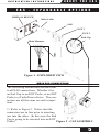
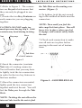
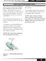
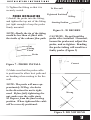
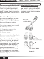
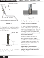
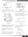
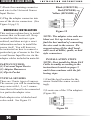
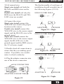
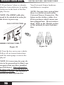
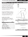
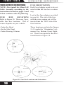
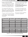
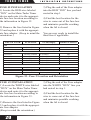
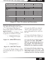
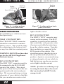
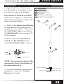
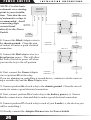
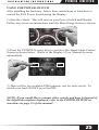
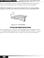
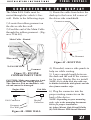
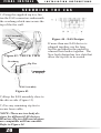
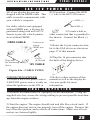
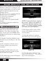
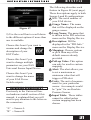
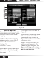
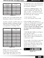
Expandable Accessory System
Installation Instructions
**read important safety information in this manual**
Table Of Contents
WARRANTY INFORMATION.............................................. 3
IMPORTANT NOTES.............................................................. 3
ABOUT THE EAS............................................................... 4
INTRODUCTION..................................................................... 4
“DAISY CHAINING” THE EAS............................................ 4
EAS - EXPANDABLE OPTIONS.............................................. 5
MAIN EAS CONNECTION.................................................. 5
“JAB” ADAPTER............................................................... 7
JUICE TO ATTITUDE CONNECTIONS................................ 7
EXPANDABLE EGT........................................................... 8
EGT CONNECTIONS.......................................................... 8
FITTING INSTALLATION.............................................................8
PROBE INSTALLATION..............................................................9
UNIVERSAL SENSOR INPUT......................................... 10
UNIVERSAL SENSOR APPLICATIONS.............................. 10
SENSOR INSTALLATION...........................................................11
UNIVERSAL INSTALLATION..................................................... 14
TURBO TIMER................................................................. 17
TURBO TIMER “COOL DOWN” CONNECTIONS................. 17
TRUCK-SPECIFIC INSTRUCTIONS........................................... 18
GENERIC INSTALLATIONS..................................................... 22
POWER SWITCH.............................................................. 23
INSTALLATION AND USER INSTRUCTIONS..................... 23
NON-EXPANDABLE EGT................................................. 26
FITTING AND PROBE INSTALLATION............................... 26
FINAL INSTALL............................................................... 27
CONNECTING TO THE DISPLAY.........................................27
SECURING THE EAS...........................................................28
EAS 12V POWER KIT...........................................................29
FINAL INSPECTION.............................................................29
MYSTYLE......................................................................... 30
USING MYSTYLE FOR EAS EDITING..................................30
STARTING MYSTYLE ......................................................... 30
UNIVERSAL SENSOR INPUT............................................. 31
CUSTOM MAPPING.................................................................. 32
EGT SENSOR.................................................................... 34
DISPLAY SETUP................................................................ 34
POWER SWITCH................................................................ 35
2
I N S T A L L A T I O N
I N S T R U C T I O N S
I M P O R TA N T
WARRANTY
A B O U T INFORMATION
T HE EA S
N O T E S
Before using your new EAS device, it is important that you update
your product. Refer to the Display Device’s User Guide for more information on how to use the Fusion update software, or visit our web
site.
Please take the time to thoroughly review all of the information outlined
in this manual. Taking the time to understand how this product works and
how to properly operate it will ensure that you have an extraordinary and
safe driving experience. If we can be of any assistance to help you get the
most from your product please call us. (See back page of this manual for
contact information)
Thank you again for your business and enjoy your new product.
IMPORTANT: Read through these instructions completely so that you
understand each step prior to installation. Refer to the Display Device
User Manual for Safety and Warranty info.
SAFETY TERMS
Throughout this User Guide (hereafter noted as User Manual or Manual)
you will see important messages regarding your safety or the protection of
your vehicle. These messages are designated by the words WARNING or
CAUTION.
WARNING indicates a condition that may cause serious injury or
death to you, your passengers or others nearby. Pay careful attention
to these Warning messages, and always comply with them. They could
save a life.
CAUTION indicates a condition that could cause damage to your vehicle. It is important to install and operate your product in conformance
with instructions in this Manual. Caution alerts you to particularly
important things that will keep your vehicle operating properly.
3
ABOU T TH E EA S
I N S T A L L A T I O N
I N S T R U C T I O N S
I N T R O D U C T I O N
Congratulations on purchasing the Expandable Accessory System (EAS)
for all your future Accessory needs.
The display devices are equipped with an expandable accessories port
which interfaces with the EAS.
With the EAS Expandable option you can add multiple accessories to the
device using a daisy-chain-style connection system.
The non-expandable options allows you to monitor a single EGT probe.
NOTE: Once the install is complete, it is necessary for your device to
be powered up so that it can recognize that you have installed an EAS
device. This will need to be done prior to using MyStyle® to configure
settings. See MyStyle® section for more information.
“DAISY CHAINING” THE EAS
In Figure 1, two EGT probes plus one JAB (Used in conjunction with
Juice Product) device are chained together. This allows the user to control
the Juice module and read Engine Exhaust temperatures in more than one
area of the vehicle.
NOTE: Always use the End Cap in any EAS Expandable assembly.
4
I N S T A L L A T I O N
E A S
-
I N S T R U C T I O N S
A BOUT T HE EA S
E X P A N D A B L E
DISPLAY DEVICE
O P T I O N S
Main Cable
JAB
EGT 1
EGT 2
Main Harness
End Cap
Figure 1 - EXPLODED VIEW
MAIN EAS CONNECTION
The following instructions are universal
to all EAS connections. Whether it be
an End Cap to an EGT Probe, or an EGT
Probe to a TurboTimer device. The connectors are all the same on each component.
1) Refer to Figure 2. Notice that the
connectors are in line prior to inserting
one into the other. (In this case, the End
Cap is going to be inserted into an EGT
Figure 2 - CAP ASSEMBLY
Probe.)
5
ABOU T TH E EA S
2) Refer to Figure 3. The connectors are Keyed which means that
they can only be plugged in one
way.
3) Locate the two Key Features on
each connector you are plugging
together.
CAUTION: DO NOT apply too
much pressure during step 4. Gold
contacts may bend during twisting.
Keys
Keyways
Nut
I N S T A L L A T I O N
I N S T R U C T I O N S
the Tab Slots on the mating connector. (Figure 3)
6) To tighten, twist the nut according to the molded-in labels near the
connectors.
NOTE: Turn until you feel the
tabs snap/lock into place. You will
know it is in place when you feel
it engage, and cannot easily undo
the nut.
7) Check each connection to make
sure all nuts are in place before
moving to the next set of instructions.
Tab Slots
Gold Contacts
Tabs
Figure 3
4) Insert the connector (contains
Nut) into it’s mating connector.
You will notice that you may have
to lightly twist the two connectors
in order for the two key features to
find one another.
5) Once the connectors are mated,
lightly push the two connectors
together and twist the nut. You will
feel the Tabs pass through the Tab
Slots.
NOTE: Twisting the nut allows the
internal tabs inside the nut to find
6
Figure 4 - ASSEMBLED EAS
I N S T A L L A T I O N
I N S T R U C T I O N S
“ J A B” A DA P T ER
JUICE TO ATTITUDE CONNECTIONS
The JAB (Juice to Attitude Bridge)
allows you to connect your Edge
Juice Module to your CS or CTS
device. This allows your CS or
CTS to communicate with and control your Juice Module. Your CS/
CTS will use the device to talk to
your Juice.
The following are instructions on
how to connect the JAB to the Juice
module.
2) Remove your old Attitude from
the vehicle.
3) Locate the connector at the end
of the JAB and plug it into the corresponding Juice connector.
NOTE: (Juice Owners Only)
There will never be a need for
more than one JAB (Juice Attitude
Bridge) since only one Juice can
be used at a time.
1) Unplug your old Attitude from
your Juice module. To do this
lightly lift up the small tab with a
small screw driver and lightly pull
the connectors apart.
NOTE: Be careful not to damage
the lock during un-install.
Snap Latch
Screw Driver
Figure 5 - ATTITUDE DISCONNECT
7
EXPANDABLE EGT
I N S T A L L A T I O N
I N S T R U C T I O N S
EGT CONNECTIONS
Required Tools
EGT stands for Exhaust Gas Temperature. This product is recommended to be used with vehicles
running diesel engines due to their
potential of getting extremely hot.
It can also be used to monitor everyday vehicle temperatures as well
as those vehicles that are pushed to
their limits.
WARNING When installing the EGT Thermocouple, wear
eye protection and protective
clothing to protect from getting
metal chips in your eyes. Also,
since exhaust manifolds can be
very hot, allow the engine to cool
before drilling. When working
under the vehicle, make sure the
parking brake is set.
CAUTION: One effective way to
avoid metal fragment contamination in your engine manifold is to
apply grease in the tip of the drill
bit and threads of your tap tool
when drilling/tapping the hole in
your manifold. Reduce pressure
on the drill when the drill breaks
through the manifold wall to reduce risk of pushing metal chips
into the manifold.
- Drill
- 1/8” drill bit or similar size
(for pilot hole)
- 21/64” (best size) or 5/16”
drill bit
- 9/16” wrench or socket
- 5/8” open end wrench
- 1/8”-27 NPT Thread Tap
- Phillips screwdriver
- 5/16” or 8mm wrench
FI TTI NG INSTALL AT ION
1) Obtain a 1/8” National Pipe Tap
(NPT) available from your hardware store.
2) Drill a 21/64” (5/16” optional)
hole through the exhaust manifold
wall.
3) Use the pipe tap to cut the
threads in accordance to the pipe
tap manufacturer’s instructions and
recommendations.
4) Remove the fitting from the
Thermocouple end and install by
tightening the tapered thread end
into the manifold.
Fitting
Tapped Hole
Exhaust Manifold Wall
Figure 6 - INSTALL FITTING
8
I N S T A L L A T I O N
I N S T R U C T I O N S
5) Tighten the fitting so that it is
securely seated.
P R OB E I NS TA LL ATI O N
1) Install the probe into the fitting,
and tighten the top nut of the fitting
just tight enough to keep the probe
firmly mounted.
NOTE: Ideally the tip of the fitting
would be less than or flush with
the inside of the exhaust flow path.
Nut
Fitting
Flush
EXPANDABLE EGT
To Fire wall
Tightened Position
90 Deg.
Starting Position
Figure 8 - 90 DEGREE
CAUTION: Do not bend the
probe after installed. If needed,
loosen the probe nut, adjust the
probe, and re-tighten. Bending
the probe tubing will result in a
faulty probe. (Figure 9)
Probe
Figure 7 - PROBE INSTALL
Correct
2) Make sure that the probe cable
is positioned to allow best path and
no bending when routing to the fire
wall.
NOTE: The probe will move approximately 90 Deg. clockwise
in the direction the nut is tightened. Before fully tightening the
nut, make sure the cable starts
90 Degrees from the final resting
position. When tightened the cable
will be correctly positioned.
Wrong
Figure 9- DO NOT BEND
9
UNIVERSAL SENSOR INPUT
I N S T A L L A T I O N
I N S T R U C T I O N S
UNIVERSAL SENSOR APPLICATIONS
The Universal Sensor Input Device
gives you the ability to monitor a
variety of sensor output readings
using your Display Device. In addition, you will be able to enter and
modify sensor data using MyStyle®
software.
This device allows you to connect up to two sensors at one time.
However, if another device is
purchased, you can “Daisy Chain”
them to read multiple sensors.
Before using your new EAS device, it is important that you update
your product. Refer to the Display
Device’s User Guide for more information on how to use the Fusion
update software.
DO NOT
CUT WIRES
This section explains how to install
the following sensors:
(1) Temperature sensors (also
known as a thermistor)
(2) Pressure sensor.
However, sensors other than what is
described, can also be used.
Figure 10 shows the Universal Sensor Input Device and the Adapters
that come in the kit. The adapter
wires are 8 feet long, and have non
terminated wire ends that can be
modified to meet the needs of any
specific sensor installation.
How these adapters are used will
be explained in more detail under
the UNIVERSAL INSTALLATION
section on page 14.
10
DEVICE
CONNECTORS
ADAPTERS
Figure 10
I N S T A L L A T I O N
I N S T R U C T I O N S
S ENS OR I NS TA LL ATI O N
This section gives step-by-step
instructions on how to install either
our Temperature Sensor and/or our
Pressure Sensors.
TEMPERATURE SENSOR
PARTS INCLUDED:
(1) Temperature Sensor
(1) Temperature Wire Harness
REQUIRED TOOLS:
-3/8” socket/wrench
-1/2” socket/wrench
-1/8”-27 NPT Thread Tap
-21/64” Drill bit
-Drill
-Thread Sealing Compound
PRESSURE SENSORS
PARTS INCLUDED:
(1) Pressure Sensor
(1) Pressure Wire Harness
REQUIRED TOOLS:
-13mm Wrench/Socket
-1/8”-27 NPT Thread Tap
-21/64” Drill bit
-Drill
-Thread Sealing Compound
NOTE: We have provided adapters
that are specific to the temperature and pressure sensors. The
two non-terminated wire adapters
(Shown in Figure 10) included in
the main kit are not needed at this
UNIVERSAL SENSOR INPUT
time. They can be set aside for any
future sensor installations.
NOTE: First install the Main EAS
Cable Assembly according to the
instructions located on pages 5
and 6 then continue with the following steps.
Both sensor installs require a hole
to be drilled and tapped. Follow
these instructions to properly create
the hole:
1) Update your product. Refer to
the Display Device’s User Guide
for more information on how to use
the Fusion update software.
2) Find the best location for the
sensor. Figure 11 (on the next
page) gives a basic example of the
temperature sensor being installed
to the side plate of a manual transmission. This location is ideal for
this particular install because the
plate can easily be removed, modified, and reinstalled without getting
any metal filings inside the transmission.)
NOTE: The wall of the object you
will be drilling into needs to be
thick enough to properly capture
the sensor’s threads.
11
UNIVERSAL SENSOR INPUT
SENSOR
I N S T A L L A T I O N
TRANS FLUID
I N S T R U C T I O N S
TAP
HOLE
COVER PLATE
TRANSMISSION HOUSING
Figure 11
3) Use the 21/64” drill bit to drill a
hole perpendicular to the face you
are drilling into.
DRILL BIT
Figure 13
5) Clean the area in and around the
tapped hole and make sure it is free
of burrs and metal fragments.
6) Apply a thread sealing compound to the sensor threads, and insert it into the tapped hole. Use the
1/2” wrench (Temp) or the 13mm
wrench (Pressure) to tighten until
snug. (Do not over tighten. Avoid
stripping the threads.)
INSTALL THE ADAPTER
Now that the Universal Sensor
Input Device and the Temperature/
Pressure sensors are secured, the
Harness Adapter can be added to
connect the two.
Figure 12
4) Tap the hole using the 1/8” NPT
pipe tap. See Figure 13.
12
Temperature sensor adapter:
1) Locate the Temperature Adapter
Harness included with the sensor.
See Figure 14.
I N S T A L L A T I O N
I N S T R U C T I O N S
UNIVERSAL SENSOR INPUT
CONNECTOR
EAS 5V DEVICE
RING TERMINAL
Figure 14
2) Remove the hardware from the
end of the mounted sensor as shown
in Figure 15.
NUT
LOCK
WASHER
RING
TERMINAL
ADAPTER
Figure 16
6) Plug the adapter connector into
one of the device connectors.
Pressure sensor adapter:
1) Locate the adapter cable included
with the sensor. See Figure 17.
WASHER
CONNECTOR
COMPOSITE
WASHER
MOUNTED
SENSOR
SENSOR CONNECTOR
Figure 15
3) Replace the hardware, including
the Adapter’s ring terminal, in the
order according to Figure 15.
4) Tighten the nut using the 3/8”
wrench or socket. (Do not over
tighten).
5) Route the remaining connector
and wire to the Universal Sensor
Input Device. See Figure 16.
Figure 17
2) Plug the small round connector
into the pressure sensor.
See Figure 18
MOUNTED
SENSOR
ADAPTER
Figure 18
13
UNIVERSAL SENSOR INPUT
3) Route the remaining connector
and wire to the Universal Sensor
Input Device.
I N S T A L L A T I O N
I N S T R U C T I O N S
Black (GROUND)
Red (POWER)
Yellow (SENSOR)
4) Plug the adapter connector into
one of the device connectors. (See
Figure 16 pg.13)
UNIV ER S A L I NS TA L L ATI O N
This section explains how to install
sensors that we do not sell. Keep
in mind that this section is generalized, and does not give exact
information on how to install the
sensor itself. You will however,
be instructed on how to connect a
particular type of sensor to the Universal Sensor Input Device via the
adapter cables included in main kit.
PARTS INCLUDED:
(1) Universal Input Device
(2) Adapter Harnesses
(1) Zip-tie Packet
TYPICAL SENSORS
There are 3 basic types of sensors.
The sensors you will be monitoring
may come with 1, 2, or 3 connections that will need to be connected
to a particular adapter wire.
Figure 19
NOTE: The adapter wire ends are
blunt cut. It is up to the user to
find the best method of connecting
the wire ends to the sensor. We
suggest using off the shelf hardware such as bullet, spade, or butt
style connectors.
INSTALLATION STEPS
NOTE: First install the Main EAS
Cable Assembly according to the
instructions located on pages 5
and 6 then continue with the following steps.
1) Find the best location for the
sensor. Install the sensor accordingly.
2) Locate one of the 3 Pin adapters.
(Figure 20)
Each adapter wire is labeled and
color coded. See Figure 19
Figure 20
14
I N S T A L L A T I O N
I N S T R U C T I O N S
3)Coil unused wire:
Single wire install-coil both the
BLACK and RED wires on the
adapter.
Double wire install-coil only the
RED since the BLACK and YELLOW wires are needed.
4) Connect the wires:
Single wire install-connect the
YELLOW wire lead to the proper
location on the sensor.
Double wire install-connect the
YELLOW wire to the sensor output
signal, and the BLACK wire to the
ground signal.
Triple wire install-connect the
YELLOW wire to the sensor output
signal, the BLACK wire to the
ground signal, and the RED wire to
the 5V reference signal.
5) Double check all connections to
ensure that they are making good
contact. If possible, use a multimeter to check continuity.
UNIVERSAL SENSOR INPUT
The final assembly of each type of
installation should resemble one of
the following Figures (22-24).
HOLE IN FIRE WALL
ADAPTER
SENSOR
Figure 22 - Single
HOLE IN FIRE WALL
ADAPTER
SENSOR
Figure 23 - Double
HOLE IN FIRE WALL
6) Plug the adapter connector into
one of the device connectors.
EAS CONNECTOR
ADAPTER CONNECTOR
Figure 21
ADAPTER
SENSOR
Figure 24 - Triple
15
UNIVERSAL SENSOR INPUT
7) If you haven’t done so already,
plug the 6 pin cable into its mating
connector on the back of the Display Device.
NOTE: The OBDII cable also
needs to be attached in order for
the device to power up.
EAS CONNECTOR
I N S T A L L A T I O N
I N S T R U C T I O N S
Your Universal Sensor hardware
installation is complete.
NOTE: You may have noticed that
there is a sticker on each of the
Universal Sensor Connectors. The
letters on the stickers, either A or
B lets you know which sensor you
have plugged into. Do not remove
them. Refer to the Mystyle section
of this manual for more information.
OBDII CONNECTOR
Figure 25
8) Turn the key-on in your vehicle.
Follow all on-screen instructions
until the main gauge screen is displayed.
NOTE: It is necessary for your device to be powered up so that it can
recognize that you have installed
an EAS device. This will need to
be done prior to using MyStyle® to
configure settings. See MyStyle®
section for more information.
16
Figure 26
I N S T A L L A T I O N
I N S T R U C T I O N S
TURBO TIMER
TURBO TIMER “COOL DOWN” CONNECTIONS
The EAS Turbo “Cool Down” Timer device keeps the engine running
according to the Display Device
settings. This allows the engine
to properly cool down before it is
shut off. This section shows how
to properly install the EAS Turbo
Timer device hardware.
VBAT (YELLOW)
For more information on how to
configure the “Turbo Cool Down”
feature, refer to the Display Device’s User Guide under the “ACCESSORY OPTIONS” menu.
PARTS INCLUDED
The following may or may not
be included in your kit. Refer to
Figures 27-29
PART
QTY
EAS Main Device.........................1
-End Cap......................................1
-Main Cable.................................1
ATM Fuse Adapters........................3
ATC Fuse Adapters.........................3
Micro2 Fuse Adapters....................2
Dodge Adapter(06-09)....................1
Dodge Adapter(2010-12)................1
RUN (WHITE)
IGN (RED)
Figure 27 - Main Device
Figure 28 - Fuse Adapters
Figure 29 - Dodge Adapters
17
TURBO TIMER
TRUCK-SPECIFIC INSTRUCTIONS
NOTE: First install the Main EAS
Cable Assembly according to the
instructions located on pages 5 and
6 then continue with the following.
FUSE
BOX
LOCATIONS
Refer to Figure 30. There are 3 possible fuse box locations. This of
course depends on your vehicle:
-Under the Hood
-On the Side Panel
-Under Steering Column
I N S T A L L A T I O N
I N S T R U C T I O N S
FUSE ORIENTATION
Each Fuse Adapter needs to be oriented within the fuse box a certain
way.
Look at the fuse adapters provided
in your kit. The side of the fuse
with the wire coming out will be
inserted into the “Hot” side of the
fuse location.
These locations are listed in Figures
31-33 under the “Orientation” column as Top, Bottom, Front, Right,
ect. These correspond to the directional labels in Figure 30.
Figure 30 - Fuse Box Locations and Orientation
18
I N S T A L L A T I O N
TURBO TIMER
I N S T R U C T I O N S
FUSE #1 INSTALLATION
1) Before using your new EAS device, it is important that you update
your product. Refer to the User
Guide for more information on how
to use the Fusion update software.
4) Plug the end of the Fuse adapter
into the YELLOW “VBAT” line
you had routed in step 1.
(NOTE: Make sure that all wires
are routed within the fuse box to
avoid the fuse box lid.)
2) Locate the YELLOW wire labeled “VBAT” on the Main Turbo
Timer device and route it to the appropriate fuse box location according to the information in Figure 31.
5) Find the best location for the
wire to come out of the fuse box
and minimize possible crushing
when the lid is closed.
3) Remove the fuse listed in Figure
31 and replace it with the appropriate fuse adapter. (Keep in mind the
orientation.)
TRUCK YEAR
FUSE BOX
You are now ready to install the
second fuse if applicable.
FUSE (amps)
ORIENTATION
GM
2001-2002
Under Hood
TBC (10amp)
Rear
2003-2007
Under Hood
TBC BATT (10amp)
Rear
2007.5-2013
Under Hood
IPC (10amp)
Rear
1994-1997
Steering Column
16 (15amp)
Bottom
1999-2001
Steering Column
4 (10amp)
Left
2002-2003
Steering Column
10 (10amp)
Left
2004-2007
Steering Column
2 (10amp)
Left
2008-2010
Under Hood
30 (10amp)
Front
2011-2013
Under Hood
46 (10amp)
Left
1998.5-2002
2003-2005
2006-2009
2010
Under Hood
Under Hood
Under Hood
Under Hood
A/C CLUTCH (10amp)
16 (10amp)
23 (10amp)
M26 (10amp)
Front
Rear
Left
Front
2011-2012
2013-2014
Under Hood
Under Hood
M27 (10amp)
44 (10amp)
Right
Right
FORD
DODGE
Figure 31 - Fuse 1 Location and Orientation
19
TURBO TIMER
FUSE #2 INSTALLATION
1) Locate the RED wire labeled
“IGN” on the Main Turbo Timer
device and route it to the appropriate fuse box location according to
the information in Figure 32.
2) Remove the fuse listed in Figure
32 and replace it with the appropriate fuse adapter. (Keep in mind the
orientation.)
TRUCK YEAR
GM
2001-2007
2007.5-2013
FORD
1994-1997
1999-2001
2002-2007
2008-2010
2011-2013
DODGE
1998.5-2002
2003-2005
2006-2012
2013-2014
FUSE BOX
Under Hood
Under Hood
Steering Column
Steering Column
Steering Column
Under Hood
Under Hood
I N S T A L L A T I O N
I N S T R U C T I O N S
3) Plug the end of the Fuse adapter
into the RED “IGN” line you had
routed in step 1.
4) Find the best location for the
wire to come out of the fuse box
and minimize possible crushing
when the lid is closed.
You are now ready to install the
third fuse if applicable.
FUSE(amps)
ORIENTATION
IGN E (10amp)
MISC ING (10amp)
17 (10amp)
19 (10amp)
45 (10amp)
77 (10amp)
52 (10amp)
Side Panel
9 (10amp)
Under Hood
28 (10amp)
Refer to “DODGE ADAPTER INSTALL” Section
Under Hood
78 (10amp)
Rear
Rear
Top
Right
Bottom
Front
Left
Bottom
Front
Rear
Figure 32 - Fuse 2 Location and Orientation
FUSE #3 INSTALLATION
1) Locate the WHITE wire labeled
“RUN” on the Main Turbo Timer
device and route it to the appropriate fuse box location according to
the information in Figure 33.
2) Remove the fuse listed in Figure
33 and replace it with the appropriate fuse adapter.
(Keep in mind the orientation.)
20
3) Plug the end of the Fuse adapter
into the WHITE “RUN” line you
had routed in step 1.
4) Find the best location for the
wire to come out of the fuse box
and minimize possible crushing
when the lid is closed.
I N S T A L L A T I O N
TRUCK YEAR
GM
2001-2005
2006-2007
2007.5-2013
FORD
1994-1997
1999-2001
2002-2003
2003-2007
2008-2013
DODGE
1998.5-2002
2003-2005
2006-2012
2013-2014
TURBO TIMER
I N S T R U C T I O N S
FUSE BOX
FUSE(#/NAME) ORIENTATION
Side Panel
BRAKE (10amp)
Side Panel
BRK (10amp)
FUSE #3 Not needed for these trucks
Steering Column
18 (10amp)
Steering Column
24 (10amp)
Steering Column
26 (10amp)
Steering Column
28 (10amp)
FUSE #3 Not needed for these trucks
FUSE #3 Not needed for these trucks
Under Hood
35 (10amp)
FUSE #3 Not needed for these trucks
FUSE #3 Not needed for these trucks
Rear
Rear
Bottom
Left
Right
Right
Front
Figure 33 - Fuse 3 Locations and Orientation
DODGE ADAPTER INSTALL
The 2006-2012 Dodge trucks require
a “Y” style adapter that plugs in
between the ignition module and the
ignition harness.
There are two types of adapters. Each
is specific to a certain set of years.
Figure 34 - (2006-2009 Trucks)
Figure 35 - (2010-2012 Trucks)
1) Locate the Dodge Adapter cables
provided in the box. (see Figures 34
and 35)
2) Locate the RED wire labeled
“IGN” on the main device and
route it through the fire wall into
the cab.
3) Connect the Dodge Adapter to
the routed “IGN” wire connector.
4) Locate the key position connectors under the dash. The 20062009 are up and inside the steering column. The 2010-2012 are
behind the key/ignition module.
5) Connect the Dodge adapter in
between the truck connectors. The
2006-2009 will be an in-line cable
coming from the steering column.
21
TURBO TIMER
Dodge
Adapter
I N S T A L L A T I O N
I N S T R U C T I O N S
Ignition
Module
Steering
Column
Stock Cable
Truck
Cable
Figure 36 - Looking up from
brake pedal (2006-2009)
GENERIC INSTALLATIONS
For installation on vehicles not outlined previously:
VBAT CONNECTION
The YELLOW VBAT connector
should be connected to constant
battery power. This could be done
by connecting to the battery itself
or any fuse that has constant power.
WARNING: DO NOT use fuses that
are for the AIR BAG/Supplement
Restraint System.
IGN CONNECTION
The RED “IGN” connector needs to
be connected to the RUN-START
circuit of the vehicle. This circuit
has power when the key is in the run
position and in the start-crank position. We recommend using a wiring
schematic of your vehicle to find this
but you can also use a meter or test
22
Dodge
Adapter
Figure 37 - Looking up from brake
pedal (2010-2013)
light to find the circuit.
RUN CONNECTION
The WHITE “RUN” connector may
or may not be necessary. The RUN
connector is used to power modules
that would other wise generate codes
if not powered while the turbo timer
keeps the vehicle running. Typically
these modules are connected to the
RUN circuit of the vehicle. This
circuit has power when the key is in
the run position and only in the run
position. Again we recommend using
a wiring schematic of your vehicle to
find this but you can also use a meter
or test light to find the circuit.
NOTE: If codes are set during or after using the turbo timer, the circuit
that was touched with RUN is the
wrong circuit.
I N S T A L L A T I O N
POWER SWITCH
I N S T R U C T I O N S
INSTALLATION AND USER INSTRUCTIONS
A single EAS Power Switch gives
you the ability to control two separate devices using your Display.
EAS DEVICE INSTALLATION
Please refer to page 5 to learn more
about the EAS system interface, then
refer to the steps below.
IN THE BOX
1
2
3
4
5
MAIN CABLE
POWER SWITCH
END CAP
ADAPTER HARNESS
ZIP TIES (NOT SHOWN)
1
2
1) Refer to the Quick Install Guide
for information on connecting the
monitor to your vehicle. Then route
the EAS Main Cable according to
the Final Install section on page 27
of this manual.
3
2) Next, connect the EAS Power
Switch and EAS Endcap to the
routed EAS Main Cable as shown.
4
ENDCAP
MAIN CABLE
POWER SWITCH
NOTE: Do not plug the Adapter Harness into the Power Switch until you
are instructed to do so.
3) Use the schematic on the following page to connect the Adapter
Harness wire leads.
BLACK (GROUND)
RED (POWER)
BLUE (SWITCH 2)
GREEN (SWITCH 1)
23
POWER SWITCH
I N S T R U C T I O N S
ADAPTER
HARNESS
CONNECTOR
BLUE
GREEN
BATTERY
POWER
RED
BLACK
NOTE: Use this basic
schematic as a starting
point to your installation. Note that the use
of automotive relays is
recommended. Avoid
connecting high
CHASSIS
GROUND
current loads
directly to the Power
Switch.
KEY
I N S T A L L A T I O N
RELAY 2
85
87
86
30
POWER
LOAD 2
4) Connect the Black Adapter wire to
the chassis ground. Clean the area
of contact to ensure a good electrical
connection.
5) Connect the Red adapter wire to a
keyed power source. This will allow
the Power Switch to power off when
you turn the key to the off position.
CHASSIS
GROUND
BATTERY
POWER
RELAY 1
85
87
86
30
LOAD 1
CHASSIS
6) Next, connect the Green Adapter
GROUND
wire to position 85 on the relay.
If you are planning on controlling a second device, continue to do the same using a second relay and the Blue Adapter wire.
7) Connect position 86 of each relay to the chassis ground. Clean the area of
contact to ensure a good electrical connection.
8) Next, connect position 30 of each relay to the battery power (+). Ensure
that the connection is clean and able to make a good electrical connection.
9) Connect position 87 of each relay to each of your Loads (i.e, the devices you
will be controlling.)
10) Finally, connect the Adapter Harness into the Power Switch.
24
I N S T A L L A T I O N
POWER SWITCH
I N S T R U C T I O N S
USING THE POWER SWITCH
After installing the hardware, follow these instructions to learn how to
control the EAS Power Switch using the Display:
1) Start the vehicle. This will turn on your Power Switch and Display.
Follow any on-screen instructions until the Main Gauge Screen is shown.
2) Press the UP/DOWN arrow keys to switch to the Stand-Alone Feature
Screen as shown below. (Refer to the Display’s User Manual for more
information)
PSA-###
PSB-###
OFF
OFF
3) There will be two available PID locations, one for each switch. To
switch your load ON/OFF press the PID.
NOTE: If you would like to rename either switch, and have it (instead of
the default description) displayed, refer to the POWER SWITCH instructions on page 35 of this manual.
25
NON-EXPANDABLE EGT
I N S T A L L A T I O N
I N S T R U C T I O N S
The non-expandable accessory system (Standard EGT Probe) provides a
single sensor allowing the user to monitor only one EGT parameter.
NOTE: The EGT sensor can not be chained and if you wish to add expandable capability, you will need to purchase a new expandable EGT.
Main
Cable
Probe
Figure 38 - STANDARD
FITTING AND PROBE INSTALLATION
These installations are similar to the Expandable probe installation. Refer
to “FITTING INSTALLATION” and “PROBE INSTALLATION” sections
under the “EGT CONNECTION” section for proper install instructions.
26
I N S T A L L A T I O N
FINAL INSTALL
I N S T R U C T I O N S
C O N N E C T I N G
The Main EAS Cable must be
routed through the vehicle’s firewall. Refer to the following steps.
T O
1) Locate the rubber grommet on
the driver side fire-wall.
2) Feed the end of the Main Cable
through the rubber grommet. (Figures 39 & 40)
T H E
D I S P L AY
3) Route the cable from below the
dash up to the lower left corner of
the driver side windshield.
Connector
Main Cable - Routed
EAS Assembly
Grommet
Fire-wall
Figure 41 - ROUTING
To EAS DEVICE
Grommet
Figure 39 - ENGINE
COMPARTMENT VIEW
CAUTION: Make sure connector is not
damaged during the routing process.
The connector lock mechanism is critical and cannot be damaged.
Engine Side
EAS Connector
Cab Side
Display
Connector
Grommet
Fire Wall
Figure 40 - FIRE WALL
4) If needed, remove side panels to
help see while routing.
5) Leave enough length between
the dash and the end of the connector for easy Display Device install.
NOTE: For a clean look, the cable can
be hidden behind the dash plastic and the
door frame weather strip.
6) Plug the connector into the
proper mating connector on the
back of the device.
NOTE: Depending on your mounting
style, refer to the mounting documents
below for proper installation:
(a) Arkon Mount: Quick Install Guide
(b) POD Mount: POD Install Manual
27
FINAL INSTALL
I N S T A L L A T I O N
S E C U R I N G
T H E
I N S T R U C T I O N S
E A S
1) Using the supplied zip ties, fasten the EAS connectors underneath
the overhang which runs across the
top of the fire wall.
EAS Assembly
Figure 44 - EAS Designs
Figure 42 - TRUCK VIEW
Overhang
Zip Ties
To Display
EAS Assembly
Figure 43
2) Keep the EAS assembly close to
the driver side. (Figure 13)
3) Use any remaining zip ties to
secure loose cable.
NOTE: There are two body designs for different EAS devices.
However, the two different designs
are compatible with one another.
Refer to Figure 44.
28
If more than one EAS device is
plugged together, use the long
zip ties provided in the packet to
connect their bodies together. The
New body design has two slots that
allow the zip ties to be seated.
I N S T A L L A T I O N
I N S T R U C T I O N S
E A S
1 2 V
All of our display devices are
shipped with an OBDII cable. This
cable is used to communicate with
your vehicle’s computer.
For older vehicles not equipped
with an OBDII port, a kit may be
purchased along with an EAS 5V
Sensor to provide vehicle parameters without OBDII.
OBDII CABLE
Plugs into
the monitoring
device
Connects to
vehicle
OBDII port
Power
& Ground
FINAL INSTALL
P O W E R
K I T
RUN position. Connect the RED
(+) wire to the KEY-ON source.
RED (+)
GND (-)
2) Locate a bolt or
other connection that is grounded to
the chassis. Connect the Black (-)
wire.
3) Route the 16 pin connector similar to the EAS device as shown on
page 27 of this manual.
4) Plug the 16 pin connector into
the back of the display device.
12V CABLE
Figure 44a - CABLE TYPES
CONNECTING POWER
1) Locate a KEY-ON power source.
A KEY-ON power source is only on
when the ignition is in the ON or
F I N A L
5) Refer to other sections of this
manual as well as the display device user guide for more
information.
I N S P E C T I O N
1) Recheck all connections for a properly secure installation. Using the
supplied wire ties, secure the wiring cabling to prevent possible heat damage from hot engine surfaces.
2) Start the engine. The engine should start and idle like a stock truck. If
the engine does not start or run properly, turn off the engine. Remove the
keys from the ignition, and re-check all connections. Make sure all connectors are fastened tightly.
29
E X P AMNYDSATBYLLEE E G T
I N S T A L L A T I O N
I N S T R U C T I O N S
USING MYSTYLE FOR EAS EDITING
This section explains how to use the
MyStyle software to configure your
sensor output data so it can be read
and interpreted properly on your
Display device.
In order for you to complete the following steps, you will need:
1) Access to a computer.
2) Display Device
3) USB Cable (See Quick Install
Guide)
4) MyStyle Program installed on
your computer.
STARTING MYSTYLE
1) Remove and unplug your Display Device from the truck completely. (For those who have laptops, do not leave the OBDII cable
plugged into the device while using
MyStyle.)
2) Double-Click the MyStyle Icon
located on your desktop or the start
menu.
Figure 45
NOTE: Look to the lower right of
the screen. There is an option to
“Check for MyStyle Software Updates”. It is always good to update
each time you open MyStyle.
6) The button in the center of the
screen will display your device’s
serial number.
7) Click the button to continue.
The following screen will appear:
3) The computer will ask you to
“Please connect your device to
continue”.
4) Plug the USB cable into your
computer and into to side of your
device and set it aside.
5) The following screen will appear
on your computer:
30
Figure 46
8) Click the button labeled “Customize EAS Devices”. The following screen will appear:
I N S T A L L A T I O N
I N S T R U C T I O N S
Figure 47
9) Use the scroll bar to scroll down
to the different options if more than
one is available.
Choose this Icon if you want to
rename and change the
description of your
EGT Probe.
Choose this Icon if you
want to change multiple
parameters on your EAS
Universal Sensor Input Device.
Choose this Icon if you
want to change the name
of your EAS Power
Switch outputs.
UNIVERSAL SENSOR INPUT
Previously in the Universal Sensor hardware install section of this
manual, it explained that you will
need to pay attention to the letter on
the connectors.
E X P AMN YD SA TB YL LE E E G T
The following describes each
feature in Figure 48 (next page).
These descriptions apply to both
Sensor A and B configurations:
1 S/N: The serial number of
your EAS device.
2 Gauge Name: The name
that will be displayed on the
gauge screen.
3 Long Name: The name that
is shown in the PID selection
menu on the Display Device.
4 Description: Will be
displayed in the “PID Info.”
menu on the Display Device.
5 Mapping: Choose custom
or pick from any of the
default sensors already
provided
6 Pull-up Value: This option
can only be used in custom
mapping.
7 Alert: The alert allows you
to set a maximum or
minimum value that will
trigger a PID alert.
8 Units: The unit of measurement for your particular
sensor. An example would
be “psia” for an Absolute
Pressure Sensor.
9 Input Table: These tables
cannot be edited unless
custom mapping has been
chosen.
“A” = Sensor A
“B” = Sensor B
31
E X P AMNYDSATBYLLEE E G T
I N S T A L L A T I O N
I N S T R U C T I O N S
1
2
3
4
5
6
7
8
9
Figure 48
CU S T OM M A P P I NG
If you chose to install a sensor that
is not called out as a default sensor,
you may chose to create custom
mapping.
1) Choose the custom mapping
option according to your type of
sensor. The two choices are:
-Voltage (V)
-Resistance (ohms)
Most sensors will have data sheets
that contain a chart of values that
you can use to input into the Mystyle chart.
32
For example, refer to the chart in
Figure 49.
In the case of a Temperature Sensor
(Thermistor), the chart will have
a temperature value (Usually in
degrees Celsius) that corresponds to
a resistance value.
NOTE: It is important that you
label your units properly. For
example, if your chart gives you
degrees in Celsius, make certain
that the Unit of Measure you input
matches that value type.
I N S T A L L A T I O N
RESISTANCE
(Ohms)
96.40
13.03
3.27
1.00
0.30
0.06
I N S T R U C T I O N S
TEMP C
-55
-25
0
25
55
105
Figure 49
E X P AMN YD SA TB YL LE E E G T
an equation to use, you will need to
calculate the input values based on
the equation variables.
2) Choose a Pull-up Value. The
values available are 10K ohm, 1K
ohm, or None. To help determine
which pull-up value to use, refer to
the following rule of thumb:
In this case, you would choose the
Resistance (ohms) Custom option.
-3 wire sensors: None
-2 or 1 wire sensors: 1K or 10K
Another example would be that of a
Pressure Sensor. In Figure 50, the
chart shows a Pressure value that
corresponds to a Voltage Value.
If for example your sensor is a
single wire Temperature sensor, and
is rated as 1K @ 25C, you would
want to use a 1K pull-up. You
want to match your pull-up value
as close to the sensor rating as
possible.
VOLTAGE
4.9
4.4
3.8
3.3
2.7
2.2
1.7
1.1
0.6
0.3
0.3
PRESSURE
(KPa)
0
10
20
30
40
50
60
70
80
90
100
Figure 50
In this case, you would choose the
Voltage (V) Custom option.
If your data sheet does not come
with a chart, but rather gives you
3) Set the alert value according to
your specific sensor.
Depending on the sensor, the alert
value will be either a maximum or
a minimum value.
For example, if you have a pressure
sensor, and you want the device
to alert you when the sensor reads
greater than or equal to 90 psi, set
up the values as shown:
Figure 51
33
E X P AMNYDSATBYLLEE E G T
4) Fill in the Unit of Measure
value. This will be displayed on
the main gauge screen. Only 4
digits are allowed.
5) Input the chart data. Most
sensors will have data sheets that
contain a chart of values that you
can input into the Mystyle chart.
These will look similar to the charts
in Figures 49 and 50 on the previous pages.
For non-linear output sensors, the
more data points you can enter, the
more accurate your custom mapping will be. When the sensor
output is linear, only the maximum
and minimum values are needed.
NOTE: You probably noticed the
button in the upper right hand
corner labeled “Switch to CNG”.
We offer CNG kits for fleet vehicles, which are not yet available to
individual users. This allows them
to modify a PID that uses temperature and pressure to calculate the
fuel level in their CNG tank.
7) Click the “Save” button, and
you will be directed to the previous
screen.
8) Click the “Save Configuration”
button to upload the changes to
your Display Device.
34
I N S T A L L A T I O N
I N S T R U C T I O N S
EGT SENSOR
If you are modifying an EGT Device, note that you are only allowed
to change the names and descriptions.
1) Update/change names and description.
2) Click the “Save” button, and
you will be directed to the previous
screen.
3) Click the “Save Configuration”
button to upload the changes to
your Display Device.
DISPLAY SETUP
Now that you have modified and
saved your Mystyle data, you can
setup and display your EGT or
Universal Sensor Input PIDs on the
Display Device.
1) Disconnect your device from
Mystyle, and reinstall it in your
truck.
2) Follow all on-screen instructions
until your main gauge screen is
displayed.
3)While viewing the main gauge
screen, choose the gauge you would
like to modify.
The image in Figure 52 will appear:
I N S T A L L A T I O N
MENU
I N S T R U C T I O N S
Engine Coolant Temp
E X P AMN YD SA TB YL LE E E G T
be what is displayed on the device.
Select New PID
Alert Settings
Gauge Color
PID Information
Exit Menu
ENTER
Figure 52
4) Select the EAS Device you created and modified in Mystyle from
the “Select New PID” options list.
5) Select the “Alert Settings” menu
for the ability to turn on or off the
alert option for your new PID. This
menu also allows you to specify the
set point at which the alert will be
triggered.
6) Exit the menu and return to the
main gauge screen to verify that the
new PID is reading correctly.
For more information regarding
the functionality of your Display
Device, refer to it’s User Guide.
POWER SWITCH
Use Mystyle to rename the Power
Switch to better fit your application.
3) Save, then exit Mystyle.
4) Disconnect your device from
your computer, and reinstall it in
your vehicle.
5) Follow all on-screen instructions
until your main gauge screen is
displayed.
6) While viewing the main gauge
screen, press the UP arrow button to
change between the gauge screens.
Refer to your Display Device user
manual for more information.
7) After locating the correct screen,
the name you had changed will appear. Pressing this button will turn
on/off your switched connection.
1) Complete the STARTING MYSTYLE section on page 30.
2) Next, modify the name and description according to your specific
application. The Button Name will
35
Copyright© 2012 REV 07
For additional questions not found in the user guide call:
Technical Support
(888) 360-3343 (Edge Customers)
8:00 am - 5:00 pm MST
-OR(888) 227-2447 (Superchips Customers)
8:00 am - 5:00 pm EST
To expedite your support call, please have your
Vehicle Information, Part Number, and Serial Number ready
prior to calling Technical Support.