1
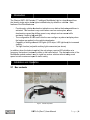
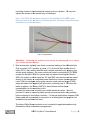
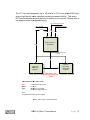
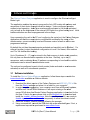
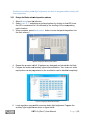
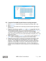
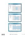
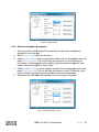
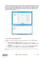
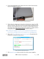
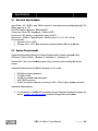
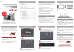
Intelligent MotoBrake Light User Manual Revision ‘C’ Hardware Ohmics, Copyright 2015. OMTL-0x (Rev-C) User Manual Page |1 Revision History Rev 01 Date 04-Jul-15 Change Description Updated for Revision ‘C’ Hardware OMTL-0x (Rev-C) User Manual Page |2 Table of Contents 1 Introduction 4 2 Installation and Operation 4 2.1 BOX CONTENTS ................................................................................................................... 4 2.2 INSTALLATION ..................................................................................................................... 5 2.3 OPERATION ........................................................................................................................ 8 2.3.1 Deceleration and applied brake (mixed) 8 2.3.2 Brake activated only 9 2.3.3 Deceleration only 9 2.3.4 Tail Light mode 9 3 Software and Firmware 10 3.1 SOFTWARE INSTALLATION .................................................................................................. 10 3.2 SOFTWARE CONFIGURATION .............................................................................................. 12 3.2.1 Design the Brake activated operation patterns 13 3.2.2 Program the Deceleration Operation Patterns and auxiliary lights output 14 3.2.3 Select operation mode 16 3.2.4 Select current pattern or sequence 17 3.2.5 Enabling/Disabling the white LED bar strobe light 18 3.3 FIRMWARE UPGRADES ...................................................................................................... 18 3.4 USING THE COMMAND LINE INTERFACE (CLI) ..................................................................... 21 4 FAQ, Known Issues, Troubleshooting 23 4.1 KNOWN ISSUES ................................................................................................................. 23 5 Specifications 24 5.1 ELECTRICAL SPECIFICATIONS ............................................................................................ 24 5.2 SYSTEM REQUIREMENTS ................................................................................................... 24 OMTL-0x (Rev-C) User Manual Page |3 1 Introduction The Ohmics OMTL-0X Revision ‘C’ Intelligent MotoBrake Light is a leap forward from the (dumb) single-action brake lights installed today by default on vehicles. Main features of the MotoBrake are: - - Provide early vehicle deceleration indication even before the brake pedal/lever is activated. This function is very useful when used on motorcycles, where deceleration caused by shifting gears is very abrupt and can cause traffic accidents if traffic is fast and tight. The configurable 40 LED matrix lets the user configure a pattern to display when the brakes are applied, or the vehicle decelerates. Capability of driving external LED lights (LED strips, LED light bars) for increased visibility. Tail light function (only with auxiliary lights connected per above) In addition, when the brake is applied, the unit pulses a centre LED white line at a frequency that makes it extremely visible to the traffic behind. The diminutive size of the MotoBrake module makes it easy to install on various vehicles without taking much space but with maximum impact to traffic safety. 2 Installation and Operation 2.1 Box contents Figure 1. Included Components OMTL-0x (Rev-C) User Manual Page |4 No 1 2 3 4 5 6 7 8 Description Intelligent Brake Light unit Revision C USB micro cable 3ft PosiTap/Lock connectors USB Dust Cap Mini Earth Magnet Universal mounting bracket Screws for universal mounting bracket Y cable adapter Qty 1 1 4 1 1 1 2 1 Figure 2. MotoBrake Package Contents 2.2 Installation The Ohmics OMTL-0x Intelligent Brake Light is provided with a universal installation bracket and hardware for the unit only. Because there are multiple ways to install the module, depending on the vehicle, hardware for particular vehicles is not provided. The unit is also supplied with a combination of four (4) Posi-Tap/Lock connectors allowing easy tapping into existing vehicle brake light wiring systems without cutting or damaging wires and, for connecting an external LED light bar or strip (not provided). Follow these simple general steps to install the OMTL-0X device: 1. Unpack the unit and identify the components. 2. Ensure your vehicle is not running and that all systems are off. 3. First install the universal bracket onto the vehicle ensuring there is access to install the two mounting screws for the unit from behind the bracket. 4. Identify the three wires that lead to the tail/brake light on your vehicle and the fourth (as applicable) that ties into the external brake lighting devices. Check your vehicle service manual for wire color coding. Ensure you mark them accordingly. 5. Identify the three connection wires on the Ohmics Intelligent MotoBrake Light, labelled as follows: a. Ground = BLACK - labelled ‘GND’. b. 12V = RED – Labeled ‘+12V’ c. Brake= WHITE or GREEN – Labelled ‘BRK’ d. Yellow= YELLOW – Labelled ‘EXT’ 6. Install the OMTL-0X device using the two M3 provided screws on the bracket. A drop of Loctite 243 or equivalent product is recommended when fastening the OMTL-0x (Rev-C) User Manual Page |5 mounting screws to avoid accidental loosening due to vibration. Do not overtighten the screws or the threads may be damaged. Note - The OMTL-0X has been designed to be installed with the LED matrix facing the rear of the vehicle in a horizontal position; otherwise the accelerometer functions may not work properly. Figure 3. Wiring identification Attention! - Connecting the conductors incorrectly can damage the unit or stress your vehicle electrical system. 7. Most motorcycles typically have three conductors leading to the tail/brake light. One is ground (GND), another is power (12V) for the tail light and the third is brake (BRK); they can be identified with a simple voltmeter or by studying your vehicle wiring diagram. On newer motorcycle models, particularly 2013+ BMW models the sensitive CAN bus system may trip when connecting the Ohmics OMTL-0x module, in which case the 12V and GND connections must be routed directly to the battery or a switched power distribution system (recommended). Later CAN bus equipped motorcycles may also send a pulsing signal (PWM) when the brake is not applied (tail light mode), switching only to 12V when the brake is applied - the Ohmics OMTL-0x has software and hardware compensation for this condition built in. Connect the three wires to match your vehicle electrical system. Use the provided Y-cable to connect multiple ground connections when using auxiliary lights connected to the Yellow conductor. For bicycle applications a special USB power cable will be provided for connection to a battery pack (not supplied, but available at local electronic stores). The brake White/Green conductor is not connected in applications where only Deceleration Mode is needed or programmed. OMTL-0x (Rev-C) User Manual Page |6 The EXT wire provides power (up to 1A) relative to GND to an external LED strip array or light bar for brake indication providing increased visibility. This wire is NOT connected when external lighting for braking is not required. Please refer to the diagram below for suggested wiring. 12V - switched power from bike BRK - Brake in from bike GND - from Bike Y CABLE Red Black White OMTL-02-Rev-C MotoBrake Black EXT - Output to auxiliary LED brake lighting Yellow Optional secondary Brake LED strip/bar Optional Brake LED strip/bar Maximum 1 amp combined load on EXT port!! OMTL-02-Rev-C Wire Color code: Red Black White Yellow = 12V switched from bike = Ground = Brake in from vehicle = Brake/Tail light PWM out Note: All signals reference to ground (GND) Figure 4. OMTL-0X (Rev-C) Connection Diagram OMTL-0x (Rev-C) User Manual Page |7 Attention! - The OMTL-0X Intelligent Brake Light performs a self-calibration sequence when powered up - this turns on the LED matrix for up to five (5) seconds. The light emitted is extremely bright and can cause eye injury if viewed directly at close distance - please exercise caution during installation and operation. 8. Mount the device on the included bracket using two M3 screws (provided). The use of Loctite 243 or equivalent product is always recommended to minimize loosening of the screws due to vibrations Note - The unit has been tested under various condition including temperature extremes, water (heavy rain) and dust exposure. However, it requires having the USB dust cap on during operation at all times except when performing firmware upgrades or device configuration. 2.3 Operation The Ohmics Intelligent MotoBrake Light (Rev-C) modes of operation are: A. B. C. D. Mixed, Deceleration and Brake activated Brake activated only - the accelerometer is disabled Deceleration only Tail Light mode (only when auxiliary lights are connected) 2.3.1 Deceleration and applied brake (mixed) In this mode the unit will turn the LED matrix on if the vehicle decelerates. As the vehicle decelerates, it will display a succession of three (LED output) user programmable patterns forming a sequence directly proportional with the deceleration. If external LED brake lights are connected, they will turn on in three levels of brightness directly proportional to vehicle decleration. When deceleration stops, the lights will return to tail light mode (dimmed). At any time, if the brakes are activated, the unit will enter Brake mode operation. In this mode, all forty (40) LED’s on the matrix will light up for 0.5 seconds; or, will display the user-chosen modulation pattern, followed by the brake pattern. In parallel, the centre White line will blink twice every 0.5 seconds (at 20Hz frequency) for higher and sustained visibility in traffic. If the auxiliary LED lights are connected, they will turn on full brightenss with a short fast initial blink or output the user-selected modulation pattern, after which they will go to a steady ‘on’ state per the user programmed output. Note - at any time the brakes are applied, the accelerometer will automatically be disabled for the duration the brakes are applied. OMTL-0x (Rev-C) User Manual Page |8 2.3.2 Brake activated only In this mode the accelerometer is disabled when using the system software configuration process. The unit will turn on the LED matrix and the auxiliary lights only when the brakes are applied. If auxiliary LED lights are connected they will activate at full brightness with a short fast initial blink or will output the user-selected modulation pattern, after which they go to a steady ‘on’ state per the user programmed output. When the brake is released the auxiliary LED lights will return to tail light mode light (dimmed). 2.3.3 Deceleration only This mode of operation is specific to vehicles that are not natively equipped with brake lights, such as bicycles, four-wheelers etc. In this case, the system relies only on the accelerometer to determine if the vehicle decelerates and accordingly, turns on the LED matrix or the auxiliary LED lights. The LED matrix and the auxiliary lights will turn off as soon as deceleration ceases. If auxiliary LED lights are connected, they will turn on and step through the userprogrammed three levels of brightness directly proportional to vehicle deceleration. When deceleration stops the lights will return to tail light mode (dimmed). 2.3.4 Tail Light mode This mode can only be activated when auxiliary LED lights are installed and connected to the EXT output of the device. When the vehicle is started the auxiliary lights will be lit at low output, with output increasing with deceleration or when brake are applied as per above modes. Tail light mode (low output) is resumed once the conditions (deceleration or braking) ceases. The level of brightenss for the auxiliary lights can be user programmed during device configuration. OMTL-0x (Rev-C) User Manual Page |9 3 Software and Firmware The Ohmics Pattern Designer application is used to configure the Ohmics Intelligent Brake Light. The application enables the users to program the forty LED matrix with patterns and sequences of their choice through interactive design. It also configures operation modes (mixed operation - brake plus accelerometer activated or just brake activated only) as well as the brightness of the external LED lights for a given braking level. Initial brake modulation can also be programmed in three steps. Upon connecting the unit to the PC and configuring the serial port, the Pattern Designer application will read the current device configuration and display the status of the accelerometer, current sensitivity level and firmware version as well as all the user programmed settings. By default the unit has the accelerometer activated and sensitivity set to ‘Medium’. For external (auxiliary) output the default configuration is Level 2 for lowest, 4 for medium and 7 for full deceleration braking. Up to 18 patterns (0 – 17) can be stored in the flash memory in brake mode operation, but only one can be selected for operation at the time. Similarly, up to six (6) sequences, each containing three (3) patterns corresponding to how hard the vehicle decelerates can be stored in accelerometer mode. The unit can be configured to work in both modes (brake activated or accelerometer activated) as well as in mixed mode operation. 3.1 Software installation To install the Ohmics Pattern Designer application, follow these steps or watch the instructional video available on Ohmics website: 1. Download the latest version of the Pattern Designer and MSP430_CDC.inf file from the Ohmics website and place it in a folder on your computer. 2. In order to run the application, your computer must have all Microsoft updates, and Microsoft VisualC 32bit libraries or it will report missing a file called msvcp120.dll when the Ohmics Pattern Designer application is launched for the first time. If that is the case please click on the Microsoft link to download and install the vcredist_x86.exe package. Note that on Windows 8.X, one needs to disable signature driver enforcement temporarily to allow the driver to install. 3. Install the vcredist_x86.exe package following the prompts. 4. Using a screwdriver, remove the USB dust cap as per attached figure. If lost, a replacement cap can be purchased at www.ohmics.com. OMTL-0x (Rev-C) User Manual P a g e | 10 Figure 5. Removing the USB protective cap 5. Connect your USB cable to the side port - the device will appear on Windows Device manager as MSP430 USB Example. The driver should install automatically as long as it can be found on your computer, otherwise choose a manual search for the driver and point to the folder on your computer where it was stored. A warning may be issued during installation that this is not a Windows signed driver - please ignore it to complete the installation process. Important note - Typical USB connections will supply between 300-500mA; some notebooks could be even less. The OMTL (Rev-C) device requires a minimum of 600mA @ 5V to operate. Therefore if the unit appears to be having issues detecting the driver, one may need to switch on the bike ignition to complement the power supplied. 6. Once installed, the device will appear as a Virtual COM port CDC (COM x) where ‘x’ can be any COM port number, under your Ports (COM&LPT) section in your Windows Device Manager as shown in the picture below. Figure 6. Installing the device driver 7. If unsure, click Start -> Right Click on My Computer -> Properties -> Device Manager and open up Ports (COM & LPT) The device will show as “Virtual COM Port CDC(COM4)”. Record the port number. 8. Launch the Pattern Designer application from the folder it was placed upon download. 9. Select File -> Serial. Configure port using the earlier recorded COM port number, OMTL-0x (Rev-C) User Manual P a g e | 11 a. speed - 9600 baud or higher, b. 8bits, 1 stop, c. no parity and no flow control. Figure 7. Configuring the serial port 10. Press ‘OK’. If the port is configured correctly the menu will report the selected port is open, otherwise an error message will appear. At the same time the ‘Sysinfo’ section will be populated with the device hardware and firmware information as shown above. 11. If no error is reported, the COM port setting is complete. The unit will also flash the selected brake and deceleration patterns to confirm successful PC connection. !!Warning!! - The LED matrix, when lit is extremely bright and could cause temporary blindness. Please exercise caution and do not stare directly into the matrix at close range when configuring the device. 3.2 Software configuration Ohmics OMTL-0X Intelligent Brake Light software configuration is done in six (6) steps: 1. Design the Brake operation patterns and load them into the flash memory (up to 18 patterns) 2. Design the Deceleration operation sequences and store them into flash memory (up to six 3-step sequences) 3. Select Sensitivity level and operation mode (mixed, accelerometer and brake activated or just brake activated) 4. Select a Pattern and respectively a Sequence for the two operation modes. 5. Configure the Brightness levels of the auxiliary brake lights. 6. Configure Brake modulation pattern. Note – The white center line of LED’s as well as the brake light modulation can be disabled or enabled depending on the local regulations for modulating rear lights. OMTL-0x (Rev-C) User Manual P a g e | 12 Similarly the auxiliary brake light brightness can also be programmed to comply with local regulations. 3.2.1 Design the Brake activated operation patterns 1. Select Braking from the left menu 2. Select Index 0-17 and design a preferred pattern by clicking on the LED icons. An LED is considered ‘on’ as indicated by the shading of the corresponding matrix location. 3. When complete, press Send pattern button to store that particular pattern into the flash memory. Figure 8. Configuring the Brake operation patterns 4. Repeat the process until all 18 patterns are designed and stored into the flash. 5. Program the matrix and auxiliary lights initial modulation. Two, four or six initial rapid pulses can be programmed or the modulation can be disabled completely. Figure 9. Configuring the Brake initial modulation 6. Local regulation may prohibit excessive brake light brightness. Program the auxiliary light brightness as shown in figure below. OMTL-0x (Rev-C) User Manual P a g e | 13 Figure 10. Configuring the auxiliary lights brightness 3.2.2 Program the Deceleration Operation Patterns and auxiliary lights output 1. Select Deceleration from the left menu and expand by clicking on the + sign 2. Select Index 0-5 3. Select Level 0 from the left menu and design a preferred pattern by clicking on the LED icons. 4. Repeat the step before to complete Level 1 and Level 2 respectively. Note that when designing the levels, think of it as a sequence starting from Level 0 to Level 2 so the patterns need to be designed in a way that would resemble a successsion sequence depending on how hard the vehicle decelerates. Level 0 pattern will always turn on first as the vehicle decelerates followed by Level 1 and respectively Level 2. 5. When complete, go back to Deceleration menu, select an index and press Send pattern button to store that particular sequence into the flash memory. 6. Repeat the process until all six sequences are designed and stored into flash. 7. Auxiliary lights brightness can be programmed for each of the 3 steps in a sequence. If local regulations prohibit brakes lights modulation or excessive brightness, all three steps in a sequence can be programmed with the same brightness level that is below permitted levels. Once the “Submit’ button is pressed, the device will play the selected sequence at the selected brightness level(s) OMTL-0x (Rev-C) User Manual P a g e | 14 Figure 11. Deceleration sequence 0, level 0 pattern design Figure 12 - Deceleration sequence 0, level 1 pattern design Figure 13. Deceleration sequence 0, level 2 pattern design OMTL-0x (Rev-C) User Manual P a g e | 15 Figure 14. Deceleration sequence 0 storing in flash and auxiliary lights output programming 3.2.3 Select operation mode 1. Select Device Config from the left menu. 2. Under Sensitivity select the level High (typical for bicycles), Medium (typical for cars) or Low (typical for motorcycles). Note that the device will read the current setting upon connection. Default is medium. Please note that sensitivity levels may be added at a later date. 3. Under Accelerometer select to have it On or Off. When disabled, the unit automatically is activated only when the brake is applied. Note that the device will read and display the current setting upon connection to the computer in the lower section of the Pattern Designer application. Default setting for the Accelerometer is On. Figure 15. Enabling or disabling the accelerometer OMTL-0x (Rev-C) User Manual P a g e | 16 Figure 16. Adjusting sensitivity 3.2.4 Select current pattern or sequence 1. Only one pattern and its respective sequence from the stored ones can be selected to run at the time. 2. Select Device Config from the left menu. 3. Under Set Acc Pattern select a sequence number from the drop down menu and press Send Command. The unit will play the sequence on its LED matrix for confirmation. When equipped with auxiliary lights the selected brightness level pattern will also be played on those lights 4. Under Set Brake Pattern select a pattern number from the drop down menu and press Send Command. The unit will play the pattern on its 40 LED matrix. Note that the center line will not play during pattern selection confirmation. 5. Disconnect the USB cable and operate your unit normally at this point. Figure 17. Selecting Deceleration sequence OMTL-0x (Rev-C) User Manual P a g e | 17 Figure 18. Selecting Brake operation pattern 3.2.5 Enabling/Disabling the white LED bar strobe light When the device is in Brake mode and if a brake is applied for longer then 500ms, a white LED bar will pulse in the center of the matrix in parallel with displaying the selected LED pattern. This bar can be enabled or disabled to conform to local bylaws regarding lighting on motor vehicles. This option is available in the Device Config menu as per picture below. Figure 19. Enabling/Disabling the white LED blinking bar 3.3 Firmware Upgrades Firmware upgrades will be necessary for future feature upgrades or bug fixes. Follow these steps for upgrading your firmware on your Ohmics Intelligent MotoBrake Light: Attention - The positioning of the small earth magnet supplied with your unit along with following the steps below is essential in putting your device in firmware upgrade mode. OMTL-0x (Rev-C) User Manual P a g e | 18 The current firmware version can be determined by connecting the brake light module to your PC via the USB cable and launching the Pattern Designer tool as seen in the figure below. If using a different operating system, a terminal utility such as Teraterm can be used and by typing “sysinfo” at the command prompt the firmware version along with system info will be displayed. Figure 20. Determining the firmware version Use these steps to upgrade the firmware: Attention - The exact order of the steps below is important for a successful upgrade. 1. Download the latest firmware and the Ohmics MotoBrake Light Firmware Upgrade utility from the www.ohmics.com website and store it on a folder on your computer. 2. Install the Ohmics MotoBrake Light Firmware Upgrade utility on your computer. 3. Ensure the unit is powered off or your vehicle ignition is switched off. Note – The unit will not enter upgrade mode if the unit is powered by any other means than USB. OMTL-0x (Rev-C) User Manual P a g e | 19 4. Position the supplied small earth magnet on the side or back of the unit where the word "UPGRADE" is etched in. Figure 21. Positioning the earth magnet for firmware programming mode 5. While holding the earth magnet in the position indicated above, plug in the USB cable into the device. The unit will enter the firmware update mode and the utility will report a device was found as seen, as shown in the figure below. Once the utility shows that a device has been detected, the magnet is no longer needed in the upgrade position and should be removed in order to continue. Note - Keeping the magnet in the position after the software has shown that the device has been detected will prevent the upgrade from completing properly. 6. Open up the Ohmics MotoBrake Light Firmware Upgrade utility and select the firmware file as shown in the figure below: Figure 22. Selecting and programming the firmware file 7. Click Upgrade Firmware button and wait for the utility to report completion. OMTL-0x (Rev-C) User Manual P a g e | 20 8. Disconnect the USB cable and replace the USB dust cap. 9. Upgrade is complete, you can operate the vehicle normally Note - Firmware upgrades will not erase the stored pattern or sequences from the flash, nor will it change the last configured settings. 3.4 Using the Command Line Interface (CLI) The Ohmics OMTL-0X Intelligent Brake Light can also be controlled via command line interface (CLI) as an alternative for users that don’t have access to a Windows machine. However, the main limitation is that the patterns and sequences will have to be requested via Ohmics website or email. The patterns can be generated and made available as binary files and then loaded via CLI by the user. The rest of the operations such as configuring the device or selecting a particular pattern are as simple as entering simple commands in at the computer prompt. A terminal application such TeraTerm can be configured. The same COM port settings as described in the software configuration settings apply. Once the terminal utility is configured, a prompt will be displayed per the attached screenshot. At the prompt type: #> #>help And the unit will return the following: help - print command list reset - reset the board senLevel <level> - set board sensitivity: <level = low, medium, high> loadAccPatt <index> <data> - load a new pattern (accelerometer only), <index = 0..5> loadBrkPatt <index> <data> - load a new pattern (brake button only), <index = 0..21> sysinfo - print system information selAccPatt <index> - select a pattern (accelerometer only), <index = 0..5> selBrkPatt <index> - select a brake pattern (brake button only), <index = 0..21> accStatus <newsts> - enable, disable accelerometer, <newsts = on, off> #> For checking or changing the sensitivity or accelerometer status, type: #> #>accStatus on #>senLevel medium #> For other commands please observe the help command return instructions. OMTL-0x (Rev-C) User Manual P a g e | 21 Figure 23. CLI mode configuration using TeraTerm OMTL-0x (Rev-C) User Manual P a g e | 22 4 FAQ, Known Issues, Troubleshooting 4.1 Known issues Issue Connecting and disconnecting the unit while Pattern Designer is still open can cause communication issues. Workaround / Fix Always ensure to open up first the configuration utility, then connect the device via USB. If disconnecting the device, ensure the application is closed, then open again. This is a known processor manufacturer limitation Cannot install the device driver in Microsoft has implanted security features Windows 8.x and 10 as it says signature in Windows 8 and part of it requires that is required drivers must be signed in order to prevent malware to affect your system. In order to install low level drivers one must disable signed drivers enforcement temporarily and the VCP driver provided will install fine. There are plenty of examples of ‘how to’ to be found on the web. When using Pattern Designer, CLI This is normal as both applications (command line interface) does not work cannot use the same COM port. In Deceleration mode the unit does not This was a very big challenge for us. We detect light decelerations have over a thousand lines of code for algorithms that detect a true deceleration and while we are continually improving it, we cannot make the unit to have a full range therefore we created more sensitivity levels to choose from. Why can’t I switch patterns or sequences Safety, Safety, Safety! The initial idea without hooking up the USB cable and my was to actually implement that feature computer? using the brake lever or pedal but we concluded it was safety issue and we removed it. Does my unit perform calibration? Yes, it does every time it powers up, in most cases quietly. In severe cases when major calibration is required the LED matrix will light up for approx. 1-2 seconds indicating the unit needs extra time for calibration. Once the matrix is off, the unit is calibrated. OMTL-0x (Rev-C) User Manual P a g e | 23 5 Specifications 5.1 Electrical Specifications Input Power: 4.5-15VDC, max. 400mA (maxim 2 amp when using auxiliary lights)@ 12V Brake input: up to 15V Red LED Matrix brightness: 1800mcd/LED Center Line White LED brightness: 1395mcd/LED Center Line LED pulsing: every 500ms twice at 20Hz Dimensions: (Width x Height x Depth): 80x40x15mm (3,1/4 x 1,5/8 x1/2 in) Environmental: Operation -20 to +50C. Storage -40 to +55C, Dust and water resistant (when USB cap is placed) 5.2 System Requirements Supported Operating System for Pattern Designer and Firmware Upgrade Utility: Windows 7 Service Pack 1, Windows 8, Windows 8.1, Windows 10. Windows XP: Only via command prompt using a terminal after installing the device drivers. Hardware Requirements for Pattern Designer or CLI mode: 900 MHz or faster processor 512 MB of RAM 50 MB of available hard disk space 5400 RPM hard drive DirectX 9-capable video card running at 1024 x 768 or higher display resolution Additional Requirements: For Windows 8.1 KB2883200 (available through Windows Update) is required as well as vcredist_x86.exe package available through Microsoft website. OMTL-0x (Rev-C) User Manual P a g e | 24