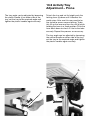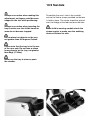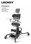
1
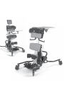
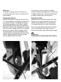
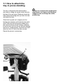
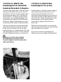
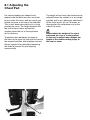
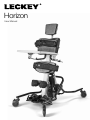
Horizon
User Manual
The Leckey Horizon Stander has
been designed to offer the option of
Supine and Prone Standing in one whilst
providing an unrivalled level of positional
support. This manual shows you how you
can quickly and easily make use of all
of the functions. The instructions on the
safety and maintenance of the product
will ensure that you will enjoy the use of
this product for a long time.
Contents
01
02
03
04
05
06
07
08
09
10
11
12
13
14
15
Intended use
Declaration of conformity
Terms of warranty
Product history record
Product training record
Safety information
How to unpack and assemble
Clinical setup for postural management
Product conversion
Frequent adjustments for daily use
Cleaning & care information
Daily product inspection
Reissuing Leckey products
Technical information
Specifications for LINAK
1 Intended Use
The Leckey Horizon Stander is for use in
prone and supine standing but may also
be used for upright standing. The Leckey
Horizon Stander is intended for adults and
children (aged 4 years+) with disabilities such
as cerebral palsy. The maximum user weight
limit on the size one Leckey Horizon Stander
is 50kg (110lbs), size two is 80kg (176lbs)
and size three 100kg (220lbs). Standing can
help the normal development of the hips, it
will help promote muscle formation, and can
help provide psychological well being.
2 Declaration of Conformity
James Leckey Design Ltd. as manufacturer
with sole responsibility declares that the
Leckey Horizon Stander conforms to the
requirements of the 93/42/EEC Guidelines
and EN12182 Technical aids for disabled
persons. General requirements
and test methods.
3 Terms of Warranty
The Warranty applies only when the product
is used according to the specified conditions
and for the intended purposes, following
all manufacturer’s recommendations (also
see general terms of sales, delivery and
payment). A two year warranty (1 year
for electrical) is provided on all Leckey
manufactured products and components.
4 Product History Record
Your Leckey product is classified as a Class
1 Medical device and as such should only
be prescribed, set up or reissued for use
by a technically competent person who
has been trained in the use of this product.
Leckey recommend that a written record is
maintained to provide details of all setups,
reissue inspections and annual inspections
of this product.
5 Product Training Record (Parents,
Teachers & Carers)
Your Leckey product is a prescribed Class
1 Medical Device and as such Leckey
recommend that parents, teachers and
carers using the equipment should be made
aware of the following sections of this user
manual by a technically competent person:
Section 6
Safety Information
Section 10
Frequent Adjustments for Daily use
Section 11
Cleaning & care information
Section 12 Daily Product Inspection
Leckey recommend that a written record
is maintained of all those who have been
trained in the correct use of this product.
6 Safety information
6.1 Always read instructions fully
before use.
6.2 Users should not be left unattended at
any time whilst using Leckey equipment.
6.3 Only use Leckey approved
components with your product. Never
modify the product in any way. Failure
to follow instructions may put the user
or carer at risk and will invalidate the
warranty on the product.
6.4 If in any doubt to the continued
safe use of your product or if any parts
should fail, please cease using the
product and contact our customer
services department or local dealer
as soon as possible.
6.5 Carry out all positional adjustments
and ensure that they are securely
fastened before you put the user into this
product. Some adjustments may require
the use of a tool which is provided with
each product. Keep all tools out of reach
of children.
6.6 When placing the user into the
standing frame, for safety reasons,
always secure the user’s feet and the
chest straps first. Then the hip and knee
straps should be fastened.
6.7 When used in the supine position it
is important to ensure the knee pad is
fastened securely. Always check the
clips are fully engaged.
6.8 Although the stander is fitted with
casters it is not a mobility device.
Always ensure that the castor brakes be
locked at all times when the frame is in
use, being adjusted or even just stored.
6.9 When adjusting the angle of the
Leckey Prone/Supine Stander ensure that
the user and all parts of the product are
well clear of surrounding furnishings to
avoid potential collisions.
6.10 It is not recommended to adjust the
height of the back pad whilst the frame is
in use and in vertical position. Other fine
positional adjustments may be carried
out safely when the user is in the frame.
It is important to support all pads
when adjusting them while the user is
in the product.
6.11 Never leave the product on a
sloping surface, greater than 5 degrees.
Always remember to lock all the castors.
6.12 The product contains components
which could present a choking hazard to
small children. Always check that locking
knobs and bolts within the child’s reach
are tightened and secure at all times.
6.13 Leckey products comply with fire
safety regulations in accordance with
EN12182. However the product contains
plastic components and therefore
should be kept away from all direct
sources of heat including naked flames,
cigarettes, electric and gas heaters.
6.14 Never place hot items on the Activity
Tray as they may damage the plastic.
6.15 Clean the product regularly. Do
not use abrasive cleaners. Carry out
maintenance checks on a regular basis to
ensure your product is in good working
condition.
6.16 The product is designed for indoor
use and when not in use should be
stored in a dry place that is not subjected
to extremes of temperature. The safe
operating temperature range of the
product is +5 to +40 deg Celsius.
6.17 The product has a battery power
source. It complies with the requirements
of BS EN 60601 Medical electrical
equipment – general requirements for
safety. Please read and adhere to the
guidelines on charging the battery
detailed in section 7.
How to
unpack and
assemble
Congratulations on purchasing your Leckey
Horizon Stander. Your Leckey Horizon
Stander will be boxed on a pallet. You should
first cut the straps and remove the outer
lid and cardboard sleeve. The tray will be
packaged separately and should be removed
from the box before trying to move the
stander. You can then remove the remaining
packaging, unlock the castors and roll the
stander off the pallet. Please check that you
have all the parts you have ordered. The
castors should then be locked into position,
facing out from the frame at 45 degrees.
Some of the components will be wrapped in
polythene packaging.
Safety First.
Keep polythene bags away from children.
7
Multi-tool
A number of adjustments will require the
use of the multi-tool, which is supplied with
each product.
If the battery is low in power an audible
bleep will sound indicating that it needs to be
charged. ‘Battery low’ will also be indicated
on both handset and control box (b).
Charging the battery
Before the product is used for the first time
it is recommended to charge the battery fully
for at least 12 hours. To charge the battery
(a), plug the adaptor into the mains socket,
attach the lead to the frame and switch on
the mains power. While charging, the charger
LED will remain orange and will turn to green
when fully charged. When charged switch
off mains power, remove the adaptor plug
and disconnect the lead from the frame. The
battery charge should be topped up each
day for approximately one hour.
Setting the Angle
Whether used in supine or prone the frame
angle can be easily adjusted with the push
button control handset or the control box.
Use angle indicator on frame for guidance.
Ensure that the product and user are away
from surrounding furnishings to prevent
possible collisions when adjusting the angle.
Safety first
Keep polythene bags away from children.
A
B
7.1 How to attach the
tray in prone standing
The tray is attached to and removed from
the frame by sliding the square metal tube into
the top of the main spine. Before you insert the
tube unlock the locking lever (a), insert the tube
and relock the lever.
To lock the tray and set its height push the
locking lever (a) down until it touches the metal
spine. After use the locking lever needs to be
fine tuned to ensure secure locking. To do this
lift up the lever and turn the nut (b) while holding
the lever in a fixed position. Push the lever back
down to check if it locks the tube securely.
Repeat the process as necessary.
A
B
Always use caution when making this
adjustment, as fingers could become
trapped in the receiving tube while
positioning.
7.2 How to attach the
tray in supine standing
7.3 How to attach
the sandals
The Tray is attached to and removed from
the frame by the metal brackets located
below the chest pad. To attach the tray slide
the metal bars into the receiving tubes to the
required depth and secure by tightening the
knobs (a) on either side.
Each sandal is attached to the footplate
individually with a single fixing bolt. Remove
the sandals from their packaging and
unscrew the plastic knob and washers.
Place the sandal on the footplate locating
the fixing bolt through the slot, place the
rubber washer on first and then the
metal washer. Secure in place with
the plastic knob (a).
Always use caution when making this
adjustment, as fingers could become
trapped in the slot while positioning.
A
A
7.4 How to attach the
headsupport & extended
headrest bracket in Supine
7.5 How to attach the
headsupport in prone
To attach and height adjust, slide the square
tubing into the top of the central spine on
the backrest. To lock the head support push
the locking lever down until it touches the
metal spine (b). To remove simply reverse
this process. The extended headrest, the
contoured head support and the Whitmyer
Pro-Series range of headsupports can also
be attached to the frame as detailed above.
If headsupport is needed in prone standing
the Leckey Interface Frame (LIF) can be
used with Horizon Stander. The LIF is
attached to and removed from the frame by
the metal brackets located below the chest
pad. To attach, slide the metal bars into the
receiving tubes to the required depth
and secure by tightening the knobs on
either side.
After use locking lever may need to be fine
tuned to ensure secure locking. To do this
lift up the lever and turn the nut (c) while
holding the lever in a fixed position. Push the
lever back down to check if it locks the tube
securely. Repeat the process as necessary.
Please refer to the specific user manual on
the Leckey Interface Frame to safely position
the frame and its accessories.
Always use caution when making
this adjustment, as fingers could
become trapped in the receiving tube
while positioning.
B
C
This frame will also accommodate the
Whitmyer pro-series range of headsupports.
7.6 How to attach
Flexible Guides
7.7 How to attach and
remove basic / flip-away /
3D footplates
To attach the flexible guides, loosen the
plastic knob (a) at the back of the pad and
slide the metal bracket into the slot. Then
when set to the desired height retighten the
plastic knob. Repeat on the other side.
To remove the footplate loosen the bolts
which attach the footplate to the bottom of
the spine (a). Slide the footplate downwards
and remove.
To attach a footplate, loosen the bolts at
either side of the footplate (a) and slide
upwards on to spine. Ensure the slider
plate is firmly inserted into groove in spine.
Tighten the bolts once the footplate is in
the required position.
A
A
Clinical setup
for postural
management
The clinical setup of the product should be
completed by a technically and clinically
competent person who has been trained in
the use of the product. Leckey recommend
a written record is maintained of all clinical
setups for this product.
8
8.1 Adjusting the
Chest Pad
For prone standing you should firstly
measure the distance from the users feet
to just under their arms and for supine you
should measure to the top of the shoulder.
This is best done were practical in a lying
position on a mat. The height between the
top of the chest pad or top and the
sandals should be set to the equivalent
of this distance.
To position the pad loosen the knob at
the back of the spine (a) and slide the pad to
the required position and retighten securely.
Always support the pad before loosening
the knob to prevent the pad slipping
unexpectedly.
A
The height of the chest pad should not be
adjusted when the stander is in an upright
position and in use. Maximum adjustment
of the chest pad is 40 cm/16 inches as
displayed on the calibration strip at the
side of the spine.
Never adjust the height of the chest
pad when the user is in the product
as the user’s weight may collapse the
height of the frame causing injury to
the user or carer.
8.2 Adjusting the Hip Pad
8.3 Adjusting the Knee
Supports
The hip pad can be height, depth and
angle adjusted for optimum pelvic position.
The height of the pad is set to the equivalent
distance between the user’s pelvis and their
feet. To adjust the hip pad loosen the four
knobs (a) on either side of the central spine
at the back of the pad and slide the pad
into the required position. Once the required
position is obtained the knobs should be
re-tightened securely.
The height and depth of the knee supports
can be positioned independently by
adjusting the mounting plate. To adjust
the plate loosen the two knobs (a) and slide
the plate and knee support to the required
position and then retighten the knobs
securely. Repeat the process for the
other plate.
Always check the pads are secure before
placing the user in the product.
To alter the width of the knee supports
and also if required achieve some rotation
loosen the knobs (b) and slide the pad to
the required position and then retighten the
knobs.
Always use caution when making this
adjustment, as fingers could become
trapped in the slot while positioning.
A
B
A
8.4 Adjusting the
Standard Footplates
8.5 Adjusting the
Flip-up Footplates
The Leckey Horizon Stander
footplates are split to allow independent
height and angle adjustment for exact
positioning of both feet. To adjust the
footplate height first loosen the allen bolts
(a) and then slide the footplate to the
required position and retighten securely.
To alter the angle of the footplate to
accommodate plantarflexion or dorsiflexion
simply rotate the coupling cylinder clockwise
or anti clockwise respectively (b).
The footplate is hinged at the front which allows
the sandals to be adjusted more easily and
can facilitate transfer from a seating position to
prone standing. To avoid any possible finger
nip issues lift the footplate at the notched area.
A
B
Use caution when lifting and
lowering the footplate as fingers
could become trapped.
8.6 Adjusting the 3D
Footplates
Loosen the three screws at the bottom of the
ball and socket joint (a). Swivel and adjust
footplate to required position and tighten
screws.
The footplate can also be adjusted to
accomodate leg position by loosening screw
(b) then you can slide left, right, backwards
and forwards. To move footplate up and
down, loosen the screw at the front of the
footplate, slide into position and retighten (c).
A
C
B
8.7 Positioning the Sandals
Each sandal is attached to the
individual footplate with a single fixing
bolt. The footplate is covered with a rubber
pad to ensure the sandals do not slide when
secured. If you wish to rotate the sandal
laterally, simply loosen the knob, place in
the required position and then re-tighten
the knob securely (a).
Use caution when lifting and
lowering the footplate as fingers
could become trapped.
A
8.8 Flexible Lateral
Support Adjustment
The flexible lateral supports can be adjusted
in height and width. To adjust the width,
loosen the knob (b) on the back of the chest
pad. Then adjust the lateral support to
the required position and finally re-tighten
the knob. To change the height, loosen as
before, slide the bracket out fully and insert
in an alternative slot (a), replace the knob
and tighten securely. As the lateral brackets
are staggered in height, additional height
range can be achieved by swapping the
lateral from the left to the right side. The
flexible lateral supports are secured around
the user by tightening the safety strap (c) into
position. Fasten the safety strap immediately.
Check the laterals are secure before
placing the user in the product. As if
they are loose the user may be at risk of
slipping into a position they cannot not
recover from and could restrict
their breathing.
A
B
C
8.9 Positioning & attaching
the Pelvic Band
There is a different pelvic band for prone
and supine standing. The pelvic band
should be attached to the user first, if
practical on a mat. The pelvic straps are
attached around the user’s pelvis and then
when the user is secured into the frame (by
their feet and chest) the longer straps are
slipped through the belt bars (a) on the back
of the hip pad and secured firmly around the
user. The additional strap with the plastic
buckle and clip (b) should be secured to
ensure the straps are not accidentally
unfastened. To ensure that you can easily
identify the strap that goes around the user
and the one that attaches to the hip pad,
a Leckey label is sewn onto the one that
attaches to the hip pad.
Always make sure the safety buckle is
engaged so the Velcro straps are not
accidentally undone which could allow the
user to slide out of the product and cause
serious injury.
A
B
8.10 Positioning
Flexible Hip Laterals
The Flexible Laterals can be used as an
alternative to the pelvic band. The Laterals
can be individually adjusted in width as well
as in height. To adjust the width loosen the
knob (a) on the back of the hip pad, then
adjust the flexible laterals to the required
position and finally re-tighten the knobs.
For the height positioning of the Laterals
loosen the allen bolt (b), position the Lateral
as required and then re-tighten the bolts
securely. The flexible Laterals supports are
secured around the user by tightening the
safety strap into position. Fasten the safety
strap immediately.
Check the laterals are secure before
placing the user in the product. As if
they are loose the user may be at risk
of slipping out of the product and could
cause them serious injury.
B
A
8.11 Activity Tray
Adjustment – Supine
The Tray is attached to and removed from
the frame by the metal brackets located
below the chest pad. To attach the tray slide
the metal bars into the receiving tubes to
the required depth and secure by tightening
the knobs (a) on either side. There are limit
poppers in the end of the tray tubes to show
the maximum depth adjustment allowed.
These may need to be depressed to
remove the tray.
The tray angle can be adjusted by loosening
the plastic handle (c) on either side of the
tray, set the tray to the required angle and
tighten the plastic handles again securely.
To adjust the height loosen the four knobs
(b), set the tray to the required position and
then retighten the knobs securely.
A
B
B
C
8.12 Activity Tray
Adjustment – Prone
To lock the tray and set its height push the
locking lever (a) down until it touches the
metal spine. After use this may need to be
fine tuned to ensure secure locking. To do
this lift up the lever and turn the nut (b) while
holding the lever in a fixed position. Push the
lever back down to check if it locks the tube
securely. Repeat the process as necessary.
The tray angle can be adjusted by loosening
the ratchet handle on either side of the tray,
set the tray to the required angle and tighten
the plastic handles again securely.
Always use caution when making this
adjustment, as fingers could become
trapped in the slot while positioning.
Always use caution when inserting the
tray to make sure the child’s hands or
arms do not become trapped.
Do not place hot objects on the tray,
not greater than 40 degrees Celsius.
Please note that the tray is for the use
of the user only. Do not lean or place
heavy objects on the tray, not greater
than 8kgs (17.6lbs).
Never use the tray to steer or push
the stander.
A
B
Do not height adjust the headsupport
beyond the hazard strip at the end of
the tube.
Always use caution when making this
adjustment, as fingers could become
trapped in the receiving tube while
positioning.
8.13 Head Support
Adjustment - Supine
The head support can be adjusted in
depth, height and angle. To height adjust,
unlock the lever (a) at the top of the central
spine, position to the desired height and
then re-lock.
For fine height, depth and angle adjustment
loosen the two knobs (b), one on either side
of the square tube, position the head support
and then re-tighten securely.
In addition to this, the contoured headrest
can be adjusted laterally. Loosen the screw
on top of the contoured headrest bar (c).
Adjust to the position required and
retighten screw.
C
B
A
Product
Conversion
9
9.1 Supine to prone
9.2 Prone to Supine
To convert the Leckey Horizon Stander to
the prone version, simply remove the head
support and attach the prone tray. Remove
the supine pelvic band and attach the prone
version. Finally loosen the sandals and turn
through 180 degrees and you are ready for
prone standing.
To convert the Leckey Horizon Stander to the
supine version, simply remove the prone tray.
Attach the required head support as defined
above. Remove the prone pelvic band and
attach the supine version. Finally loosen the
sandals and turn through 180 degrees and
you are ready for supine standing.
Supine
Prone
Frequent
adjustment
for daily use
Parents and carers should be shown how
to make frequent adjustments and made
aware of the safety checks in section 6 by
a technically and clinically competent person
who has been trained in the use of the
product. Leckey recommend that a written
record is maintained of all parent and
carers who have been trained in the use
of this product.
10
10.1 Transferring the user
into and out of the stander
10.2 Charging the battery
Before transferring the child into the stander
carry out the daily product inspection as
outlined in section 12 of this user manual.
Before the product is used for the first time
it is recommended to charge the battery
(a) fully for at least 12 hours. To charge the
battery, plug the adaptor into the mains
socket, attach the lead to the frame and
switch on the mains power. While charging
the charger LED will remain orange and
will turn to green when fully charged. When
charged switch off mains power, remove the
adaptor plug when and disconnect the lead
from the frame. The battery charge should be
topped up each day for approximately one
hour.
We would recommend that users are never
transferred straight from seating to standing
without preparation and stretching. This is
best done in lying position whilst on a mat
but can be carried out in a wheelchair or
seating system if required.
Before transferring the child into the product
lock all the castors, ensuring that they
are facing outwards to maximise product
stability. Make sure the straps on the flexible
laterals supports, the pelvic band and
sandals are released and out of the way
to facilitate transfer.
Always secure the pelvic band or
flexible hip pads first and then the flexible
lateral supports.
10.3 Setting the Angle
If the battery is low in power an audible bleep
will sound and ‘battery low’ will be indicated
on the handset and control box (b), indicating
that it needs to be charged. Please note that
there is a ‘Stop’ button (c) on the front of the
control box for use in emergencies.
Whether used in supine or prone the frame
angle can be easily adjusted with the push
button control handset or the control box.
There is also an angle adjustment sticker on
the frame for guidance.
Ensure that the product and user are
away from surrounding furnishings to
prevent possible collisions when
adjusting the angle.
Do not put your hands or fingers behind
the knee supports while adjusting
the angle of the product as they could
become trapped.
A
C
B
10.4 Flexible Lateral
Supports
10.5 Flexible Hip Pads
The flexible lateral supports are secured
around the user by clipping the plastic
buckle into its receiver. The safety strap
(a) can then be tensioned if required.
The flexible hip pads are secured around
the user by clipping the plastic buckle into
its receiver. The safety strap (b) can then be
tensioned if required.
Check the laterals are secure before
placing the user in the product. As if
they are loose the user may be at risk of
slipping into a position they cannot not
recover from and could restrict
their breathing.
Check the hip pads are secure before
placing the user in the product. As if
they are loose the user may be at risk
of slipping out of the product and could
cause them serious injury.
B
A
10.6 The Front Knee
Supports
10.7 Activity Tray
Adjustment – Supine
The knee brackets come as standard with
knee supports; these should always be
used when the user is in supine but can also
be used for prone standing for additional
support and security. To fasten the pad insert
the plastic clip into the buckle on the side of
the main knee support. Then grab the straps
ends and pull firmly away from the user,
which will secure the pad around the users
leg. To remove the pad simply squeeze the
tabs on the top and bottom of the plastic clip
and the pad will pop off (c).
The Tray is attached to and removed from
the frame by the metal brackets located
below the chest pad. To attach the tray slide
the metal bars into the receiving tubes to
the required depth and secure by tightening
the knobs (a) on rather side. There are limit
poppers in the end of the tray tubes to show
the maximum depth adjustment allowed.
These may need to be depressed to
remove the tray.
To adjust the height loosen the four knobs
(b), set the tray to the required position and
then retighten the knobs securely.
Always check with your therapist as to
the correct tensioning of the straps for
your child as the kneecap is a sensitive
area and too much force could
cause injury.
C
A
B
B
10.8 Activity Tray
Adjustment – Prone
The tray angle can be adjusted by loosening
the plastic handle (c) on either side of the
tray, set the tray to the required angle and
tighten the plastic handles again securely.
To lock the tray and set its height push the
locking lever (a) down until it touches the
metal spine. After use this may need to be
fine tuned to ensure secure locking. To do
this lift up the lever and turn the nut (b) while
holding the lever in a fixed position. Push the
lever back down to check if it locks the tube
securely. Repeat the process as necessary.
The tray angle can be adjusted by loosening
the ratchet handle on either side of the tray,
set the tray to the required angle and tighten
the plastic handles again securely.
A
B
C
10.9 Sandals
Always use caution when making this
adjustment, as fingers could become
trapped in the slot while positioning.
Always use caution when inserting the
tray to make sure the child’s hands or
arms do not become trapped.
Do not place hot objects on the tray,
not greater than 40 degrees Celsius.
Please note that the tray is for the use
of the user only. Do not lean or place
heavy objects on the tray, not greater
than 8kgs (17.6lbs).
Never use the tray to steer or push
the stander.
To position the user’s feet in the sandals
secure the Velcro straps provided so the foot
is held in place. The straps should be placed
over the bridge of the foot and over the toes.
If the child is wearing sandals check the
straps regular to make sure the webbing
does not irritate the skin.
11 Cleaning & Care
Information
How to Maintain
1. It is advisable to charge the battery for
at least one hour everyday. However if the
powered actuator is not operating and you
have checked that the handset is connected
correctly you should stop using the product
immediately and contact your local dealer.
2. At least once a week, check that all fixings
and fastenings including the castors are in
good condition.
3. The Leckey Horizon Stander is
manufactured from nylon coated metal,
ABS plastic and plywood. When cleaning
the frame we would recommend that you
use warm water and a non-abrasive
detergent.
4. When any parts of or accessories are not
in use, we would advise that you store then
together in a safe place for future use.
6. For heavier soiling use a mild propietary
cleaner and warm water ensuring that
cleaning products aare fully removed.
7. Body fluids should be removed promptly
with cold water and then cleaned as above.
8. Water and oil based stains may be
removed by using most water based
household propietary spray cleaning agents,
following instructions carefully.
9. For extreme soiling and infection control,
use a 5% sodium hypochlorite (bleach)
solution, using clean warm water to ensure
excess products is removed.
10. Removable parts can be machine
washed at 40° – Line drying is
recommended.
11. Gentle Low Heat tumble dry is required.
5. If you are in any doubt as to the safe use
of your Leckey Horizon Stander please cease
from using the product and contact your
local dealer as soon as possible.
Metal and plastic and wooden
components
1. Soap and water or antibacterial spray can
be used for daily cleaning.
Upholstery and fabrics
1. Clean and care for your fabric on a regular
basis and it will maintain its condition and
appearance.
2. For deep cleaning a low pressure steam
cleaner can be used.
2. Simply vacuum to remove dust particles
and wipe with a damp cloth for general
cleaning.
3. Microfibre cloths are extremely effective
without soap, which is helpful as soap can
clog your fabric.
4. Remove spillages promptly with an
absorbent dry cloth such as above.
5. Take care not to cause abrasive damage.
3. Do not use solvents to clean plastic
wooden or metal components.
4. Make sure the product is dry before use.
5. Check all wooden components regularly to
ensure there are no cracks or splitters.
12 Daily Inspection
13 Re-issuing Leckey
Products
Daily Product Inspection (Therapists,
parents & carers)
We recommend that daily visual checks of
the equipment are carried out by therapists,
carers or parents to ensure the product is
safe for use. The recommend daily checks
are detailed below.
1. Ensure all adjustment knobs and bolts are
in place and secure.
Most Leckey products are assessed and
ordered to meet the needs of an individual
user. Before reissuing a product we
recommend that the therapist prescribing
the product has carried out an equipment
compatibility check for the new user and has
ensured that the product being re-issued
contains no modifications or special
attachments.
2. Check all upholstery for signs of wear and
tear.
3. Check all castors are moving freely and
lock securely.
4. Check all Velcro strips and brush fluff to
ensure straps secure firmly.
If in any doubt to the continued safe use of
your Leckey product or if any parts should
fail, please cease using the product and
contact our customer services department or
your local dealer as soon as possible.
A detailed technical inspection should be
carried on the product prior to re-issuing.
This should be carried out by a technically
competent person who has been trained in
the use and inspection of the product. Please
refer to section 12 for the required checks to
be carried out.
Ensure the product has been cleaned
thoroughly in accordance with section 11 of
this manual.
Ensure a copy of the user manual is supplied
with the product. A copy can be downloaded
from our website www.leckey.com.
Leckey recommend that a written record is
maintained of all product inspections carried
out during the reissue of the product.
If in any doubt to the continued safe use of
your Leckey product or if any parts should
fail, please cease using the product and
contact our customer service department or
your local dealer as soon as possible.
14 Technical Data
Product and accessory codes
For product sizes insert size 1, 2 or 3 in
place of #.
For fabric colour options insert: GB, BB, PB or GRB in place of XXX.
Colour key:
GB = Green / Black (Available size 1 and 2 only)
BB = Blue / Black (Available size 1, 2 and 3)
PB = Pink / Black (Available size 1 and 2 only)
GRB = Grey / Black (Available size 3 only)
Horizon Prone Stander
The Horizon Prone Stander comes complete
with tray, knee supports, laterals, basic
footplate and your choice of pelvic band and
sandals as specified at time of order.
LHZ/#/156-XXX
Horizon Supine Stander
The Horizon Supine Stander comes as per
the Horizon Prone Stander but with the
addition of a head support and supine
pelvic band.
LHZ/#/157-XXX
Accessories
Head Lateral Support (Size 1 fits Size 3)
LHZ/#/117-XXX
Hip Laterals
LHZ/#/164-XXX
Chest Laterals
LHZ/#/168-XXX
Flip Away Hip Laterals (Size 3 Only)
LHZ/3/153-XXX
Flip Away Chest Laterals (Size 3 Only)
LHZ/3/154-XXX
Sandals
LHZ/#/100
Supine Tray (Size 2 fits Size 3)
LHZ/#/143
Prone Tray (Size 2 fits Size 3)
LHZ/#/158
Padded Tray Insert (Size 2 fits Size 3)
CAS/#/109
Wooden Tray Supine (Size 3 Only)
LHZ/3/143
Grab Rail (Size 2 fits Size 3)
LHZ/#/192
Grab Posts (Size 2 fits Size 3)
LHZ/#/193
Hip Plate Assembly
LHZ/#/172-XXX
Backrest Assembly (Size 2 fits Size 3)
LHZ/#/171-XXX
Headsupport Assembly (Size 2 fits Size 3)
LHZ/#/169-XXX
Flip-Up Footplate Assembly
LHZ/#/161
3D Footplate Assembly (One size fits all)
LHZ/#/160
Contoured Headsupport (One size fits all)
LHZ/1/180
Supine Belt
LHZ/#/181-XXX
Prone Belt
LHZ/#/182-XXX
Standard Knee Assembly (Size 2 fits Size 3)
LHZ/#/167-XXX
Medium Extended Knee Assembly (Size 2 fits Size 3)
LHZ/#/183-XXX
Long Extended Knee Assembly (Size 2 fits Size 3)
LHZ/#/184-XXX
Medium Extended Knees - Brackets Only
(Size 2 fits Size 3)
LHZ/#/185
Long Extended Knees - Brackets Only
(Size 2 fits Size 3)
LHZ/#/186
Headsupport Assembly - Extended 4”
(Size 2 fits Size 3)
LHZ/#/187-XXX
Conversion Kit to Supine
LHZ/#/190-XXX
Conversion Kit to Prone
LHZ/#/191-XXX
14 Technical data
Size
2
1
3
Age (approx)
min 4
max 10
Size
1
mm
9
14
18
Adult
2
3
inches mm
inches m m
inches
44.7
1280
50.4
1280
50.4
Width 580
(without tray)
22.8
640
25.2
640
25.2
Height in Horizontal Position 780
30.7
805
31.7
805
31.7
Weight of Product 44kg
97lbs
50kg
110.6Lbs
59kg
130lbs
Max User Weight 50kg
110Lbs
80kg
176Lbs
100kg 220lbs
User Standing Height
min 1000
max 1400
39.4
55.1
1400
1800
55.1
70.9
1550
1800
61
70.9
Shoulder Height
(footplate to top of pad)
min 820
max 1150
32.3
45.3
1000
1450
39.4
57
1000
1450
39.4
57
Hip Pad Height
(footplate to top of pad)
min 450
max 750
17.7
29.5
750
950
29.5
37.4
750
1150
29.5
45.3
Hip Pad Width
min 175
max 270
6.9
10.6
210
390
8.3
15.3
310
470
12.2
18.5
Knee Height
(footplate to middle of pad)
min 250
max 450
9.8
17.7
400
550
15.7
21.6
400
650
15.7
25.6
Width Between Chest
Laterals
min 200
max 300
7.9
11.8
240
380
9.4
14.9
340
460
13.4
18.1
10°
10°
10°
10°
10°
Length 1135
Footplate Angle Adjustment
+/- 10°
Tray Sizes 420
x 440
Tray Angle Adjustment 0° to
Prone Version 40°
16.5 520
x 17.3 x 590
20.5 520
20.5
x 23.2 x 590 x 23.2
0° to
40°
0° to
40°
0° to
40°
0° to
40°
0° to
40°
Tray Angle Adjustment 20°/30° 20°/30° 20°/30° 20°/30° 20°/30° 20°/30°
Supine Version
Frame Clearance 155
(bottom of ski to ground)
6.1
180
7
180
7
15 Customer – James Leckey
Specifications for LINAK
Products supplied
LINAK Actuator
343200-0020004X
Rated IP54
Duty Cycle: 2/18 – 2 minutes continuous
use followed by 18 min not in use.
Ambient temperature +5° to +40° C
Push Max 10,000N
Pull Max 6000N
Self Lock at 10,000N Push, 6000N Pull
Typical speed with full load 5mm/sec
Max amps at load of 6000N is 7 amps
Noise level below 50 dB (A)
Power input voltage 24v +- 10%
LINAK Control Box
CBJC0033-01
Rated IP: IP54
Duty Cycle Max 10% or 6 minutes per
hour followed by 18 min not in use.
Ambient temperature +5° to +40° C
Rated Capacity 2.9 Ah 24v
Lead acid gel filled battery
LINAK Handset
HD8X052-00
Rated IP54
Control current 100mA per channel (Max)
Ambient temperature +5° to +40° C
LINAK Battery Charger - CH01
Mains 100-240 VAC/50-60 Hz switch mode
power supply
Charging voltage 27.6 VDA +- 2%
Charging current Max 500mA
Green LED for power on
Yellow LED for charging funcion
Yellow LED turns into green when batteries
are fully charged.
Linak products may be stored in non-heated
storage facilities with humidity between
0 and 100%, none condensing.
None condensing means that one should
not take a product an ice cold warehouse
into a room with a temperature of 20deg C;
if this is done then moistness will appear
on the products.
Leckey
19 Ballinderry Road
Lisburn
BT28 2SA
Northern Ireland
United Kingdom
T: 028 9260 0750
E:[email protected]
W:www.leckey.com
24 hour postural
care for babies,
kids & adults.
Sleeping, Sitting,
Standing, Walking,
Moving, Bathing,
Toileting.
LS119-06