1
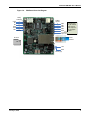
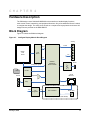
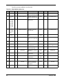
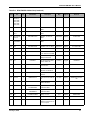
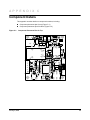
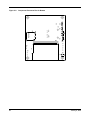
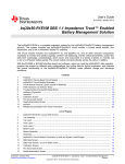
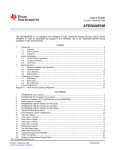
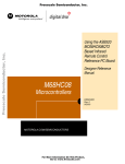
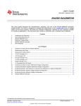
Stellaris® Ethernet-Enabled Intelligent Display Module (IDM) Reference Design Kit User ’s Manual RDK-IDM-0 5 Co pyrigh t © 2 008– 201 0 Te xas In strumen ts Copyright Copyright © 2008–2010 Texas Instruments, Inc. All rights reserved. Stellaris and StellarisWare are registered trademarks of Texas Instruments. ARM and Thumb are registered trademarks, and Cortex is a trademark of ARM Limited. Other names and brands may be claimed as the property of others. Texas Instruments 108 Wild Basin, Suite 350 Austin, TX 78746 http://www.ti.com/stellaris 2 January 6, 2010 Stellaris® Intelligent Display Module RDK User’s Manual Table of Contents Chapter 1: Stellaris® Ethernet-Enabled Intelligent Display Module ............................................................ 7 Kit Contents ........................................................................................................................................................ 8 Using the RDK .................................................................................................................................................... 8 Board Overview .................................................................................................................................................. 8 Chapter 2: Hardware Description .................................................................................................................. 11 Block Diagram .................................................................................................................................................. 11 Functional Description ...................................................................................................................................... 12 Microcontroller and Networking (Schematic page 1) .................................................................................... 12 Microcontroller .......................................................................................................................................... 12 Debugging................................................................................................................................................. 12 Ethernet .................................................................................................................................................... 12 LCD Panel and Peripherals (Schematic page 2) .......................................................................................... 12 LCD Panel................................................................................................................................................. 13 Touch Panel .............................................................................................................................................. 13 RS232 Serial Port ..................................................................................................................................... 13 Relay ......................................................................................................................................................... 13 Analog Inputs ............................................................................................................................................ 13 Audio Transducer...................................................................................................................................... 13 MicroSD Card Slot .................................................................................................................................... 14 Power Supplies (Schematic page 3)............................................................................................................. 14 PoE Operation (applies to MDL-IDM only)................................................................................................ 14 +5 V Operation (applies to MDL-IDM28 only) ........................................................................................... 14 Chapter 3: Software Development ................................................................................................................ 15 Software Description......................................................................................................................................... 15 Source Code..................................................................................................................................................... 15 Tool Options ..................................................................................................................................................... 15 Programming the IDM....................................................................................................................................... 16 Appendix A: Schematics................................................................................................................................ 19 Appendix B: Bill of Materials (BOM) ............................................................................................................. 23 Appendix C: Component Details ................................................................................................................... 29 January 6, 2010 3 List of Figures Figure 1-1. Figure 1-2. Figure 2-1. Figure 2-2. Figure C-1. Figure C-2. 4 Intelligent Display Module ............................................................................................................... 7 IDM Board Overview Diagram......................................................................................................... 9 Intelligent Display Module Block Diagram ..................................................................................... 11 Debug Connection Pinout ............................................................................................................. 12 Component Placement Plot for Top .............................................................................................. 29 Component Placement Plot for Bottom ......................................................................................... 30 January 6, 2010 Stellaris® Intelligent Display Module RDK User’s Manual List of Tables Table B-1. MDL-IDM28 Bill of Materials.......................................................................................................... 23 Table B-2. RDK-IDM Bill of Materials.............................................................................................................. 26 January 6, 2010 5 6 January 6, 2010 C H A P T E R 1 Stellaris® Ethernet-Enabled Intelligent Display Module The Stellaris Intelligent Display Module (IDM) Reference Design (RDK-IDM) is a compact QVGA touch-panel module for automation and instrumentation applications. The design is based on the Stellaris® LM3S6918 microcontroller; a highly integrated controller incorporating a 32-bit ARM® Cortex™-M3 core. A key feature of the standard IDM is the Power over Ethernet (PoE) power system that facilitates both network and power connections with a single CAT5 cable. 10/100 Ethernet capability connects the IDM to an array of networks—from dedicated industrial networks to the internet. The IDM example software application includes source code for an embedded web server. In addition to the POE-equipped IDM included in the RDK, there is also an IDM28 available. IDM28 has an identical feature set, including 10/100baseT Ethernet, but without the Power over Ethernet capability. Users should start development with the standard RDK-IDM and transition to MDL-IDM28 for production if PoE is not required. Development of software for the RDK-IDM is simplified by using the StellarisWare® comprehensive graphics library and ARM development tools from our tools partners. The IDM Reference Design Kit includes the touch panel module (MDL-IDM), a documentation CD, power supply, and cables. This user's manual provides comprehensive information on the reference design hardware and software. Figure 1-1. January 6, 2010 Intelligent Display Module 7 Kit Contents The RDK-IDM reference design kit supports both the MDL-IDM and the MDL-IDM28, and comes with the following: MDL-IDM Intelligent QVGA Touch Panel with Ethernet Power supply – 24 V/15 W – Plug adaptors for US, UK, EU, and Australia Retractable Ethernet cable – 10/100baseT Debug adapter – Adapts 10-pin fine-pitch ARM JTAG connector to standard 20-pin connector Reference Design Kit CD – Complete documentation, including Quickstart and User's Guides – Graphical User Interface (GUI) installer – Complete source code, schematics, and PCB gerber files The source code can be modified and compiled using any of the following tools: Keil™ RealView® Microcontroller Development Kit (MDK-ARM) IAR Embedded Workbench Code Sourcery GCC development tools Code Red Technologies development tools Texas Instruments’ Code Composer Studio™ IDE Using the RDK The recommended steps for using the RDK are: Follow the Quickstart guide included in the kit. The Quickstart guide will help get the display module up and running in minutes. Use your preferred ARM tool-chain and the Stellaris Graphics library to develop a touch-panel application. Software applications are loaded into IDM flash memory using a JTAG/SWD debug interface. See Chapter 3, “Software Development,” for the programming procedure. The Stellaris Graphics Library Software Reference Manual and the Stellaris Peripheral Driver Library Software Reference Manual each contain specific information on software structure and function. Customize and integrate the hardware to suit an end application. This user's manual is an important reference for understand circuit operation and completing hardware modification. Board Overview Figure 1-2 shows an overview of the board. 8 January 6, 2010 Stellaris® IDM RDK User’s Manual Figure 1-2. IDM Board Overview Diagram Relay Contacts 3 2 1 COM NC NO GND RXD TXD RS232 3 2 1 1 2 3 4 5 6 Analog Inputs AIN0 AIN1 AIN2 AIN3 GND +5.0V input SD Card +5.0V terminal may be used for power input or power output on PoE-equipped models. 10/100 Ethernet 1GB +24V GND 24Vdc (opt) January 6, 2010 9 10 January 6, 2010 C H A P T E R 2 Hardware Description The IDM design uses a Stellaris® LM3S6918 microcontroller to handle display functions, touch-screen control, networking, and peripheral functions. Only a few additional ICs are needed to complete the design. The entire circuit is built on a compact four-layer printed circuit board. All design files are provided on the RDK-IDM CD. Block Diagram Figure 2-1 shows the IDM block diagram. Figure 2-1. Intelligent Display Module Block Diagram Analog 4 x ADC Data QVGA LCD Panel LCD Driver +5V Ctrl Analog touch signals 1GB Stellaris LM3S6918 Microcontroller RS232 Serial microSD SPCO 10/100 Ethernet Speaker Relay +3.3V 3.3V Regulator +5V PoE Controller 24Vdc Jack PoE Components (not included in MDL-IDM28) January 6, 2010 11 Functional Description This section describes the IDM’s hardware design in detail. Microcontroller and Networking (Schematic page 1) Page 1 of the schematics details the microcontroller, Ethernet, and debug interfaces. Microcontroller At the core of the IDM is the Stellaris LM3S6918 microcontroller with integrated Ethernet MAC and PHY. The Stellaris microcontroller operates at up to 50 MHz using an internal PLL. The LM3S6918 microcontroller has an internal LDO voltage regulator that supplies 2.5 V power for internal use. This rail requires only three capacitors for decoupling and is not connected to any other circuits. A reset switch and R-C network connect to the microcontroller’s RSTn input. An external reset circuit is not required by the LM3S6918 microcontroller, so the R-C components simply serve to filter any noise on the reset line. Debugging The microcontroller supports JTAG and SWD debugging as well as SWO trace capabilities. To minimize board area, the RDK uses a 0.050” pitch header which matches ARM’s fine-pitch definition (Figure 2-2). Some in-circuit debuggers provide a matching connector. Other debuggers can be used with the ADA1 adaptor board included in the RDK. Figure 2-2. Debug Connection Pinout 1 2 +3.3V GND GND n/c GND TMS /SWDIO TCK/SWCLK TDO TDI SRSTn 9 10 Ethernet The Ethernet jack (P1) integrates a RJ-45 connector, Ethernet magnetics, surge suppression, and additional pins for Ethernet power connection. The jack supports power over the two unused CAT-5 pairs as well as the signal pairs. The Power over Ethernet (PoE) circuit is covered on page 3 of the schematic. A single LED provides Ethernet link and traffic information. Refer to the LM3S6918 microcontroller data sheet for information on the display modes for this LED. The schematic and PCB have provision for an LED to be mounted on the LCD side of the display. This capability would allow a short light-pipe to provide front-panel display of Ethernet traffic. LCD Panel and Peripherals (Schematic page 2) Page 2 of the schematics contains the LCD panel connections, serial communication, relay, speaker, analog inputs, and a microSD card slot. 12 January 6, 2010 Stellaris® IDM RDK User’s Manual LCD Panel The LCD panel (U2) is a 2.8” TFT panel with an integrated controller (ILI9320). The display memory resides in the LCD panel, allowing the microcontroller to access the panel as a peripheral. The LCD panel requires only a 3 V power supply which also simplifies system design. A 16-bit data path is used to improve access rates. Only two control lines (RDn, WRn) are required for reading and writing to the panel. A third signal (RS) selects between memory and control register access. In order to meet reset signal timing requirements. The microcontroller also controls the panel’s reset signal (RSTn). The LCD panel incorporates a white LED backlight which is controlled by the microcontroller using PC6/CCP3 and MOSFET Q3. Most applications will use backlighting at full brightness by setting GPIO PC6 HIGH. Because the forward voltage of each LED is typically 3.5 V, the 75Ω resistors set LED current to 20mA for a total panel current of 80mA. For additional LCD panel information, refer to the data sheets on the RDK-IDM CD and LCD driver source code in the StellarisWare Graphics library. Touch Panel Four ADC channels and four GPIO lines connect directly to the resistive touch panel, allowing the microcontroller to manage all aspects of operation. X and Y axis position measurements are made independently. For X-axis measurement, GPIO pins PC4 and PC5 are set HIGH and LOW respectively to form a resistor divider between 3 V and 0 V. The voltage on ADC6 and ADC7 indicates the X-axis position. To measure the Y-axis position, PD0 and PD1 are set HIGH and LOW respectively and the voltage on ADC4 or ADC5 is measured. Software controls calibration and finger press detection functions. RS232 Serial Port The MAX2331 (U3) line transceiver interfaces between UART 1 and the RS232 port pins. The transceiver incorporates a power saving feature that turns off its internal power supply if a valid RS232 level is not present on its receive pin. This feature should be considered if connecting to a device other than a PC serial port. Relay A single-pole, double-throw relay is available for general-purpose use. When connecting an external load, do not exceed the ratings listed in the MDL-IDM data sheet. If an inductive load is used and powered from a DC source, a flywheel diode should be connected across the load to reduce arcing as the relay switches off. Analog Inputs Four analog inputs add measurement capability to the IDM. Refer to the MDL-IDM data sheet for electrical limits for these inputs. A transient voltage suppressor (U6) adds electrostatic discharge (ESD) protection. Audio Transducer SPK1 is a small magnetic audio transducer which is driven by PC7/CCP4 through a small power MOSFET. CCP4 can be configured to generate a free running tone at the required frequency. Note that the audio transducer is polarized. January 6, 2010 13 MicroSD Card Slot Standard microSD media may be used for image or data storage. The SD card is wired for use in SPI mode, rather than the 1-bit or 4-bit SD modes. Power Supplies (Schematic page 3) The third schematic page contains the complete Power over Ethernet (PoE) power supply circuit. PoE Operation (applies to MDL-IDM only) PoE (IEEE 802.3af) is a specification for supplying 48 V at up to 15 W to a device over a standard CAT5 cable. The IDM can operate in Mode A, where power is received from Ethernet signal lines, or in Mode B, where power is received from the unused signal pairs. All PoE signaling, including device class identification, is handled by an LM5071 controller. Implementation of the 802.3af standard does not require software or Ethernet transactions. The PoE controller’s under-voltage lock-out circuit prevents the IDM from operating at less than 35 V. In order to support an alternative 24 Vdc power source, a simple circuit using transistor Q6, changes the under-voltage lock-out to around 12 V when a local supply is present. The IDM’s PoE circuit is fully isolated to 250 Vdc. The voltage potential between the Ethernet signals and GND on the module must not exceed this limit under both normal and fault conditions. The PoE switching power supply generates 5 Vdc power for backlighting, audio transducer, and the relay. A 5 Vdc power output is available on the terminal block for powering external sensors. A 3.3 V LDO voltage regulator provides microcontroller and digital circuit power. +5 V Operation (applies to MDL-IDM28 only) MDL-IDM28 does not support PoE operation. Instead, an external +5 V supply must be provided to the terminal block (see Figure 1-2 on page 9). The power supply should provide +5 V ±5% at 300 mA. 14 January 6, 2010 C H A P T E R 3 Software Development This chapter provides general information on software development as well as instructions for Flash memory programming. Software Description The software provided with the IDM provides access to all of the peripheral devices supplied in the design. The Stellaris Peripheral Driver Library is used to operate the on-chip peripherals, the Stellaris Graphics Library is used to render graphical displays on the touch screen, and a set of board-specific drivers are provided to access the off-chip functionality on the IDM. The Stellaris Graphics Library provides two levels of support for rendering graphical elements. In the lowest level, basic drawing primitives are provided, such as lines, circles, rectangles, and text rendering. Each primitive supports clipping to a single clipping rectangle, allowing only a portion of the display to be affected by the drawing primitives. Building upon the drawing primitives is a widget set, which combines the drawing of graphical elements with reactions to pointer events (in this case, presses on the touch screen). The widget set includes push buttons, check boxes, radio buttons, and drawing canvases. By using the widget set, complex interactive graphical displays can be constructed quickly. A set of drivers for the on-board peripherals is also provided. This includes a driver for the touch screen, the audio transducer, the relay, the analog inputs, and the MicroSD card. Since the PoE signaling is handled entirely in hardware and, therefore, imposes no requirements upon the software, any of the TCP/IP stacks that support the Stellaris Ethernet interface can be used on the module. The IDM is also supplied with a set of example applications that utilize the Stellaris Peripheral Driver Library and the Stellaris Graphics Library, along with the board-specific drivers for the on-board peripherals. These applications demonstrate the capabilities of the IDM, and provide a starting point for the development of the final application for use on the IDM. All example applications are integrated with the Stellaris boot loader to allow automatic firmware updates to be performed over Ethernet using the LM Flash Programmer application. Source Code The complete source code for the IDM is included on the RDK-IDM CD. Refer to the Quickstart Guide for a detailed description of initial RDK hardware set up and how to install the source code. The source code and binary files are installed in the DriverLib tree. Tool Options The source code installation includes directories containing projects and/or makefiles for the following tool-chains: Keil™ RealView® Microcontroller Development Kit (MDK-ARM) IAR Embedded Workbench Code Sourcery GCC development tools Code Red Technologies development tools Texas Instruments’ Code Composer Studio™ IDE January 6, 2010 15 Evaluation versions of these tools may be downloaded from www.ti.com/stellaris. Note that, due to code size restrictions, the evaluation tools may not build all example programs for the IDM. A full license is necessary to re-build or debug all examples. Instructions on installing and using each of the evaluation tools can be found in the Quickstart guides (for example, Quickstart-Keil, Quickstart-IAR) which are available for download from the evaluation kit section of our web site at www.ti.com/stellaris. For detailed information on using the tools, refer to the documentation included in the tool chain installation or visit the website of the tools supplier. Programming the IDM The IDM software package includes pre-built binaries for each of the example applications. If you installed DriverLib to the default installation path of C:/DriverLib, you can find the example applications for the IDM in “C:/DriverLib/boards/rdk-idm”. The LM Flash Programmer is a free tool for programming Stellaris microcontrollers. It can be used in two modes to update the firmware on the IDM. All IDM example applications are designed for use with the Stellaris boot loader which supports updating of the main application firmware over Ethernet. Alternatively, the LM Flash Programmer utility can be used in conjunction with any Stellaris evaluation board to program the IDM. The Stellaris evaluation board acts as a USB-to-JTAG/SWD hardware interface and should be used in cases where the boot loader image is not present or where the main application image is not behaving correctly and cannot receive the Ethernet signal telling it to transfer control to the boot loader. However, in normal operation, it is more convenient to program via Ethernet. To program example applications into the IDM using the Ethernet-based firmware update: 1. Install the LM Flash Programmer utility on a Windows PC. 2. Ensure that the IDM is connected to the same subnet of your Ethernet as the Windows PC that will be used to program the device. 3. Apply power to the IDM. 4. Run LM Flash Programmer. 5. In the Configuration tab, select “Manual Configuration - see below” in the “Quick Set” list. 6. Select “Ethernet Interface” in the list below “Interface” and fill in the IP and MAC addresses for the IDM you are trying to program. Each example application shows this information somewhere on the IDM display. Note that it may take several seconds for the IP address to be allocated. 7. If your PC has multiple network adapters, select the appropriate adapter in the “Ethernet Adapter” list. 8. Move to the Program tab and click the Browse button. Navigate to the example applications directory (the default location is “C:/DriverLib/boards/rdk-idm/”). 9. Each example application has its own directory. Navigate into the example directory that you want to load and then go to the /gcc directory which contains the binary (*.bin) files. Select the application binary file and click Open. Files that start with a “bl_” prefix are boot loader images and cannot be updated using this method. 10. Click the Program button to start the download process. 11. The program starts once the download is complete. 16 January 6, 2010 Stellaris® IDM RDK User’s Manual To replace the boot loader image or to program example applications into the IDM using a Stellaris evaluation board to provide JTAG/SWD functionality: 1. Install LM Flash Programmer on a Windows PC. 2. Connect the 10-pin to 20-pin adapter (included in the RDK) to the evaluation board ribbon cable. This converts the standard 20-pin ARM header on the evaluation board to a fine pitch ARM header. 3. Carefully connect the socket of the adaptor board to J1 on the IDM. 4. Apply power to the IDM and connect the evaluation board (available separately) to a USB port. 5. Run LM Flash Programmer. 6. In the Configuration Tab use the Quick Set control to select LM3S6965. These settings are compatible with the LM3S6918 implementation on the IDM. 7. Move to the Program Tab and click the Browse button. Navigate to the example applications directory (the default location is “C:/DriverLib/boards/rdk-idm/). 8. Each example application has its own directory. Navigate into the example directory that you wish to load and then into the /gcc directory which contains the binary (*.bin) files. Files named with a "bl_" prefix are Stellaris boot loader images while those without the prefix are main application images. Select the binary file and click Open. 9. Set the "Erase Method" to "Erase Necessary Pages" and check the "Verify After Program" box. NOTE: Setting "Erase Entire Flash" when attempting to replace a main application image will erase the boot loader image and result in a hang when the IDM next boots. If this occurs, reflash a boot loader image using these instructions. 10. If flashing a boot loader image, set the "Program Address Offset:" value to 0x0000. If programming a main application image, set this value to 0x1000. 11. Next, click on the Program button to start the Erase, Download, and Verify process. 12. Program execution will start once Verify is complete. The Debuggers in each of the tool-chains also include Flash programming capabilities, including support for high-performance in-circuit debug interfaces. The IDM design uses a Stellaris® LM3S6918 microcontroller to handle display functions, touchscreen control, networking, and peripheral functions. Only a few additional ICs are necessary to complete the design. The entire circuit is built on a compact four-layer printed circuit board. All design files are provided on the RDK-IDM CD. January 6, 2010 17 18 January 6, 2010 A P P E N D I X A Schematics This sections contains the schematic diagrams for the Intelligent Display Module. IDM Microcontroller and Networking on page 20 IDM LCD Panel and Peripherals on page 21 IDM Power over Ethernet Circuit on page 22 January 6, 2010 19 Schematic page 1 LCD_DB[0..15] P3V3 Stellaris Microcontroller R1 U1 Reset 1 3 SSICLK CARD_CS_N SSIRX SSITX 2 4 KMR221GLFS GPIOA0 GPIOA1 GPIOA2 GPIOA3 (bottom side) C1 0.1UF GPIOA[0..3] LCD_RST_N RELAY 72 73 74 75 1 2 5 6 19 18 PE0/SSI1CLK PE1/SSI1FSS PE2/SSI1RX PE3/SSI1TX ADC0 ADC1 ADC2 ADC3 PD0 PD1 PD2/U1RX PD3/U1TX ADC7 ADC6 ADC5 ADC4 PF0 PF1 PF2/LED1 PF3/LED0 TOUCH_YP TOUCH_YN RXD TXD TOUCH_YN TOUCH_YP TOUCH_XN TOUCH_XP LED4 Green LCD_RD_N LCD_WR_N LCD_RS P3V3 P3V3 LED0 43 TXOP 46 TXON OMIT 330 P3V3 C8 0.1UF Ethernet PoE 10/100baseT MDIO 10K TXOP LED3 PF3/LED0 47 61 60 59 58 C2 10pF C3 10pF PG0/I2C1SCL PG1 ISOLATED P1 1 TD+ 7 CT 1CT:1 TX+ TXRX+ 64 LM_RST_N 25MHz Y1 1 XTALNPHY XTALPPHY 17 16 OSC0 48 49 2 OSC1 8MHz Y2 C4 18PF C5 18PF 1 C9 18PF 2 C10 18PF 52 53 50 51 65 76 9 15 21 33 39 42 45 54 57 63 69 82 85 86 87 94 4 97 RST XTALNPHY XTALPPHY TXON RXIP 8 TD- 40 (bottom side) Ethernet LEDs R6 R9 MDIO Green 330 10 11 12 13 95 96 99 100 (bottom side) 2 RXIP 1 2 3 4 5 1CT:1 RD+ RX- 6 7 8 OSC0 OSC1 XOSC0 XOSC1 WAKE HIB CMOD0 CMOD1 GND GND GND GND GND GND GND GND GND GND GND GND GND GND GND GND AGND AGND RXIN ERBIAS AVDD AVDD VDD33 VDD33 VDD33 VDD33 VDD33 VDD33 VDD33 VDD33 VDD33 VDD33 VDD33 VBAT LDO 37 9 RXIN RD- R2 41 P3V3 12.4K, 1% 3 98 P3V3 8 20 32 36 44 56 68 81 83 84 93 55 C11 0.1UF 12.4K 1% resistor required on Pin 41 for compatibility with future LM3S6918 revisions. See product change notification. P3V3 C13 C14 C15 C16 C17 0.01UF 0.01UF 0.1UF 0.1UF 4.7UF C6 10pF C7 10pF 5 10 6 11 VC1+ VC1VC2+ VC2- C12 0.01UF GL GR SW1 PC0/TCK/SWCLK PC1/TMS/SWDIO PC2/TDI PC3/TDO/SWO PC4/CCP5 PC5/C1+/C0o PC6/CCP3 PC7/CCP4 49.9, 1% TOUCH_XN LCD_BL SOUND CON-HDR-2X5-050_0 80 79 78 77 25 24 23 22 OMIT LED2 LED1 R8 Debug TCK/SWCLK TMS/SWDIO TDI TDO TOUCH_XP TOUCH_XP TOUCH_XN Power LEDs R60 49.9, 1% 10K 2 4 6 8 10 P3V3 LED1 LCD_DB0 LCD_DB1 LCD_DB2 LCD_DB3 LCD_DB4 LCD_DB5 LCD_DB6 LCD_DB7 R11 10K J1 1 3 5 7 9 66 67 70 71 92 91 90 89 49.9, 1% R4 PB0/CCP0 PB1/CCP2 PB2/I2S0SCL PB3/I2C0SDA PB4/C0PB5/C1PB6/C0+ PB7/TRST R10 P3V3 R3 PA0/U0RX PA1/U0TX PA2/SSI0CLK PA3/SSI0FSS PA4/SSI0RX PA5/SSI0TX PA6/CCP1 PA7/I2C1SDA 49.9, 1% P3V3 26 27 28 29 30 31 34 35 R7 LCD_DB8 LCD_DB9 LCD_DB10 LCD_DB11 LCD_DB12 LCD_DB13 LCD_DB14 LCD_DB15 10K RJ45_PoE_JK0-0044 VC2N VC2P VC1N VC1P ISOLATED 7 P2V5 VDD25 VDD25 VDD25 VDD25 14 38 62 88 C18 C19 C20 0.01UF 0.1UF 4.7UF LM3S6918 Texas Instruments Title Intelligent LCD Board Size A Date: Document Number Rev C tbd Sheet 1 of 3 Schematic page 2 P3V3 2.8" TFT LCD Panel R1IN EN INVALID FORCEON 8 2 10 3 7 8 10 9 LCD_CS_N 16 FORCEOFF P3V3 LCD_RS LCD_RD_N LCD_WR_N CON-HDR-1X3-100 MAX3221 31 6 1 MMSD4148 8 nc - NC COM 10 RLY_NO 1 1 RLY_NC 2 5 RLY_COM 10K 10K 10K R44 J3 NO 11 21 U11 TVS_MMQA5V6T1G CS RS RD WR LEDK1 LEDK2 LEDK3 LEDK4 RESET IM0 IM3 TOUCH_YP TOUCH_YN 17 18 19 20 LEDK1 LEDK2 LEDK3 LEDK4 R14 R15 R16 R17 75 75 75 75 Q3 G LCD_BL NDS331N KWH028Q02-F03 R45 (bottom side) 10K P3V3 3 P3V3 D RLY_N + R23 Z1 3 2 D1 R55 P5V0 R54 10K LCD_RST_N Y+ Y- 1 3 4 6 1 0.01UF 13 TOUCH_XP TOUCH_XN 13 15 5 R1OUT 14 12 T1OUT 12 14 2 1 T1IN X+ X- DB10 DB11 DB12 DB13 DB14 DB15 DB16 DB17 C56 9 C2- J2 GND 11 RXD 23 24 25 26 27 28 29 30 0.1UF D 0.1UF 6 TXD LCD_DB8 LCD_DB9 LCD_DB10 LCD_DB11 LCD_DB12 LCD_DB13 LCD_DB14 LCD_DB15 C29 0.1UF 4.7UF 16 S 7 V- C23 0.1UF 0.01UF C2+ C28 LEDA C22 0.1UF C55 C1- DB0 DB1 DB2 DB3 DB4 DB5 DB6 DB7 0.01UF 5 0.1UF 1 2 3 4 22 35 36 37 0.01UF 0.1UF 4 LCD_DB0 LCD_DB1 LCD_DB2 LCD_DB3 LCD_DB4 LCD_DB5 LCD_DB6 LCD_DB7 C53 0.1UF C27 VCC VCC2 VCI C26 C21 C24 GND GND C25 P5V0 C54 U2 LCD_DB[0..15] 3 V+ VCC C1+ 5 34 U3 2 6 33 32 15 P3V3 TERM_3.5MM_3P R26 10K R58 10K R57 J4 SPK1 2 D8 1 2 1 MMSD4148 33 GPIOA-0 1 R22 33 GPIOA-1 2 GPIOA2 R24 33 GPIOA-2 3 GPIOA3 R25 33 GPIOA-3 4 9 R21 GPIOA1 SSIRX 2908-05WB-MG CSS-73B16K D GPIOA0 + - SSICLK SOUND C30 Q7 G (bottom side) P2 1 2 3 4 5 6 7 8 CARD_CS_N SSITX 33 R59 10K 12 S P5V0 11 NDS331N R20 10K 10 Q1 G RELAY V23026D1021B201 P3V3 1 3 4 6 GPIOA[0..3] S NDS331N R53 200K, 1% 0.1UF microSD Card Slot 5 U6 TVS_MMQA5V6T1G 6 5 2 P5V0 TERM_3.5MM_6P Texas Instruments Title Intelligent LCD Board Size A Date: Document Number Rev C tbd Sheet 2 of 3 Schematic page 3 24V - 48V Power Input R43 1 3 2 D7 1 V_EXT_IN 2 1 0.39 ohm, 1W, 1% R50 24.9K, 1% ISOLATED 2 PJ-102AH 2 S3BB-13-F Q6 1 D3 CMPT5401 2 3 R51 24.9K, 1% 1 T1 1 MMSD4148 P5V0 8 7 D2 1 POE_SEC L1 2 1 POE_DC 2 C31 MBRS540T3 0.18uH C35 C36 470UF 0.1UF 10uF, 6.3V 2 10uF, 6.3V 10uF, 6.3V OMIT R27 590K, 1% XFMR_C1588-AL POE_PRI 24.9K, 1% 1.00K, 1% +5V to +3.3V 300mA Power Supply R48 200K, 1% R36 150, 1% POE_OUT POE_CS 100, 1% 12 11 16 8 Si4848DY 1.0uF, 16V R35 Description 0 12/21/07 A 1/10/08 Change to 16 bit LCD IF B 2/7/08 Change LCD to -F03 Omit C35 & C50 Add R56 & R57 Remove U4 & U5; Add microSD Add LED1, LED2, & LED4 Change sound to P5V0 Change to 3.3V regulator Vc Vout Nr 5 C42 4 4.7UF R34 R38 590, 1% C45 22.1k, 1% 0.1UF C48 LM5071MT-50 0.047uF Vin 1.0uF, 16V R56 10K U10 R41 12.4K, 1% 3 0.39 ohm, 1W, 1% C46 1000pF C49 C44 2 R33 POE_VEE History 10.0, 1% C43 PQ1X331M2ZPH NR 1 4 10 9 13 U8 GND R32 POE_COMP 2 C51 1 0.047uF 4 Prototype release 3 R40 C LED nc1 COMP nc4 FB E POE_CMP GND 1000pF POE_C 0.1UF POE_SS AC2 VC2N POE_RCLASS POE_RT C47 VIN VCC RSIG UVLO OUT UVLORTN CS AUX RCLASS COMP RT FB SS ARTN VEE RTN Q2 POE_LED POE_AUX HD01 POE_VCC U9 1 2 5 6 4 3 14 15 7 5 6 7 8 P3V3 1.0uF, 16V 1 2 3 + R29 20.0, 1% C40 1 - POE_UVLO 100K, 1% 33.2K, 1% R49 D6 D5 AC1 VC2P R30 POE_UVLORTN VC1N R31 0.047uF SMAJ60A AC2 C41 POE_RSIG HD01 2 AC1 POE_VC R28 + POE_UVLOC 8/18/08 10uF, 6.3V 2 4.7uF, 100V C38 1 2 C37 1 4.7uF, 100V 4 D4 - C C34 R52 5 6 VC1P Date C33 3 POE_VIN Rev C32 1 2 R39 1.00K, 1% 8 C50 NOTE: OMIT For Non-PoE Version (IDM28) omit all components on this page except for +5V to +3.3V Power Supply. 6 7 POE_FB 5 R42 7.32K, 1% 1.00K, 1% FOD2712 Populate C35. Add VDD connection to R10,R11. Add 12.4K to U1.41 for future compatibility. Add notation for non-PoE variant. C52 1500pF, 250V Texas Instruments Title Intelligent LCD Board ISOLATED Size A Date: Document Number Rev C tbd Sheet 3 of 3 A P P E N D I X B Bill of Materials (BOM) Table B-1 provides the BOM for the IDM28 module (MDL-IDM28) and Table B-2 on page 26 provides the BOM for the IDM RDK (RDK-IDM). Table B-1. MDL-IDM28 Bill of Materials Item Ref Qty Part Number 1 C2,C3,C6,C7 4 C0603C100J5GACTU 2 C4,C5,C9,C1 0 4 C0603C180J5GACTU 3 C1,C8,C11, C15,C16,C19 ,C21,C22,C2 4,C25,C26, C27,C28, C29,C30, C36,C45,C47 18 ECJ-1VB1H104K 4 C12,C13, C14,C18, C53,C54, C55,C56 8 5 C17,C20, C23,C42 6 Mfg Supplier Stock No Capacitor 10pF 50V 5% Ceramic NPO/COG 0603 Kemet Mouser 80-C0603C100J5G Capacitor 18pF 50V 5% Ceramic NPO/COG 0603 Kemet Mouser 80-C0603C180J5G Capacitor 0.1uF 00603 50V X7R 5% Panasonic Digikey PCC2398CT-ND C0603C103J5RACTU Capacitor, 0.01uF 50V 5% 0603 X7R Kemet Mouser 80-C0603C103J5R 4 LMK212BJ475KG-T Capacitor 4.7uF 16V X5R 0805 Taiyo Yuden Digikey 587-1298-2-ND C31,C32, C33,C34 4 C0805C106K9PACTU Capacitor 10uF 6.3V X5R 0805 Kemet Mouser 80-C0805C106K9P 7 C35 1 EEE-FK0J471GP Capacitor, 470uF 6.3V Electro, Low Z, SMT Size F Panasonic Digikey PCE4308CT-ND 8 C37,C38 2 C5750X7R2A475M Capacitor 4.7uF 100V X7R 2220 TDK Digikey 445-1450-2-ND 9 C40,C43, C44 3 C0805C105Z4VACTU Kemet Mouser 80-C0805C105Z4V 10 C41,C49,C51 3 ECJ-1VB1H473K Panasonic Digikey PCC2286CT-ND 11 C46,C48 2 C0603C102K5RACTU Capacitor 1000pF 0603 X7R 50V 10% Kemet Digikey 399-1082-1-ND 13 C52 1 GRM188R72E152KW07D Capacitor 1500pF 250V X7R 0603 Murata Digikey 490-3528-1-ND 14 D1,D3,D8 3 MMSD4148T1G Diode, Switching 200mA 100V SOD-123 OnSemi Digikey MMSD4148T1GOSCT-ND 15 D2 1 MBRS540T3 Diode, Schottky 5A 40V SMC OnSemi Digikey MBRS540T3GOSCT-ND 16 D4,D6 2 HD01-T Rectifier, Bridge 0.8A 100V MiniDIP SMT Diodes Digikey HD01DICT-ND 17 D5 1 SMAJ60A-E3/1 TVS 60V 400W DO-214AC Vishay Digikey SMAJ60A-E3/1GI-ND 18 D7 1 S3BB-13-F Diode, 3A 100V SMB Diodes Digikey S3BB-FDICT-ND 19 J1 1 M50-3600542 Connector, 2x5 Header 1.27mm pitch, SMT Harwin Mouser 855-M50-3600542 January 6, 2010 Description Capacitor 1uF 16V Y5V 0805 Capacitor 0.047uF 50V X7R 0603 23 Table B-1. MDL-IDM28 Bill of Materials (Continued) Item Ref Qty Part Number Description Mfg Supplier Stock No 20 J2 1 90120-0763 Header 1x3 0.1" pitch unshrouded Molex Digikey WM8085-ND 21 J3 1 ED555/3DS Terminal Block 3 pos LP 3.5mm black On Shore Tech Digikey ED1515-ND 22 J4 1 ED555/6DS Terminal Block 6 pos LP 3.5mm black On Shore Tech Digikey ED1518-ND 23 J5 1 PJ-102AH CUI Digikey CP-102AH-ND 24 LED1,LED3 2 LTST-C171GKT LiteOn Mouser / Arrow LTST-C171GKT 25 L1 1 DO1813H-181MLB Coilcraft Coilcraft DO1813H-181MLB 27 P1 1 JK0-0044 Connector, RJ45 with PoE 10/100 magnetics, shielded TH Pulse Sager JK0-0044 28 Q1,Q3,Q7 3 NDS331N Mosfet N-Ch SOT-23 20V 1.3A Fairchild Arrow NDS331N 29 Q2 1 Si4848DY Mosfet N-Ch SO-8 150V 3.7A Vishay Digikey SI4848DY-T1-E3CT-ND 31 Q6 1 CMPT5401 Transistor, PNP 150V 500mA SOT-23 Central Semi Mouser 610-CMPT5401 32 R1,R3,R4,R9, R20,R23,R26 ,R44,R45,R5 4,R55,R56,R 58, R59 14 ERJ-3GEYJ103V Resistor, 10K 5% 0603 Panasonic Digikey P10KGCT-ND 33 R6,R60 2 ERJ-3GEYJ331V Resistor 330 ohms 5% 0603 Panasonic Digikey P330GCT-ND 34 R7,R8,R10,R 11 4 ERJ-3EKF49R9V Resistor 49.9 Ohms 1% 0603 Panasonic Digikey P49.9HCT-ND 35 R14,R15,R16 ,R17 4 ERJ-3GEYJ750V Resistor, 75 ohms 5% 0603 Panasonic Digikey P75GCT-ND 36 R21,R22,R24 ,R25,R57 5 ERJ-3GEYJ330V Resistor, 33 ohms 5% 0603 Panasonic Digikey P33GCT-ND Connector, 2.1mm DC power socket high-current LED, 0805 SMT Green Inductor 0.18uH 10A DO1813H 37 R27 1 ERJ-3EKF5903V Resistor 590K 1% 0603 Panasonic Digikey P590KHCT-ND 38 R28,R50,R51 3 ERJ-3EKF2492V Resistor 24.9K 1% 0603 Panasonic Digikey P24.9KHCT-ND 39 R29 1 ERJ-3EKF20R0V Resistor 20.0 1% 0603 Panasonic Digikey P20.0HCT-ND 40 R30 1 ERJ-3EKF3322V Resistor 33.2K 1% 0603 Panasonic Digikey P33.2KHCT-ND 41 R31,R39,R40 3 ERJ-3EKF1001V Resistor 1.00K 1% 0603 Panasonic Digikey P1.00KHCT-ND 42 R32 1 ERJ-3EKF10R0V Resistor 10.0 1% 0603 Panasonic Digikey P10.0HCT-ND 43 R33 1 ERJ-3EKF1000V Resistor 100 1% 0603 Panasonic Digikey P100HCT-ND 44 R34 1 ERJ-3EKF2212V Resistor 22.1K 1% 0603 Panasonic Digikey P22.1KHCT-ND 45 R35,R43 2 ERJ-1TRQFR39U Resistor 0.39 1% 2512 Panasonic Digikey PT.39YCT-ND 46 R36 1 ERJ-3EKF1500V Resistor 150 1% 0603 Panasonic Digikey P150HCT-ND 47 R38 1 ERJ-3EKF5900V Resistor 590 1% 0603 Panasonic Digikey P590HCT-ND 48 R2, R41 2 ERJ-3EKF1242V Resistor 12.4K 1% 0603 Panasonic Digikey P12.4KHCT-ND 49 R42 1 ERJ-3EKF7321V Resistor 7.32K 1% 0603 Panasonic Digikey P7.32KHCT-ND 50 R48,R53 2 ERJ-3EKF2003V Resistor 200K 1% 0603 Panasonic Digikey P200KHCT-ND 24 January 6, 2010 Stellaris® IDM RDK User’s Manual Table B-1. MDL-IDM28 Bill of Materials (Continued) Item Ref Qty Part Number Description Supplier Stock No Panasonic Digikey P100KHCT-ND CUI Digikey 102-1197-1-ND C&K / ITT Digikey 401-1427-1-ND 51 R49 1 ERJ-3EKF1003V 52 SPK1 1 CSS-73B16K Transducer, Audio 2.5-4.5V 16ohm 8.5mm SMD 53 SW1 1 KMR221GLFS Switch, Momentary Tact 200gmf 2.8x4.6mm 54 T1 1 C1588-AL Transformer, Flyback 7W for LM5070 Coilcraft Coilcraft C1588-AL 55 U1 1 LM3S6918 IC, Microcontroller ARM Cortex TQFP-100 Luminary Luminary LM3S6918 56 U2 1 KWH028Q02-F03 LCD Panel, 2.8" with Touch Screen Formike Formike KWH028Q02-F03 57 U3 1 MAX3221CAE+ IC, RS232 Driver/Receiver 1/1 SSOP-16 Maxim Digikey MAX3221CAE+-ND 58 U4 1 AT45DB081D-SU IC, Data Flash 1Mbit 2.7V SOIC-8 Atmel Digikey AT45DB081D-SU-ND 59 U6,U11 2 MMQA5V6T1G TVS, Quad 5.6V 50W SC74 On Semi Digikey MMQA5V6T1GOSCT-ND 60 U8 1 PQ1X331M2ZPH IC, Voltage regulator 3.3V 300mA SOT23-5 Sharp Digikey 425-2333-2-ND 61 U9 1 LM5071MT50/NOPB IC, PoE PD Interface w/AUX & PWM controller National Semi Future Electronics LM5071MT-50-LF 62 U10 1 FOD2712R1V Optically Isolated Error Amplifier Fairchild Digikey FOD2712R1VCT-ND 63 Y1 1 NX5032GA25.000000MHZ Crystal, 25.00MHz 5.0x3.2mm SMT NDK Digikey 644-1041-2-ND 64 Y2 1 NX8045GB8.000000MHZ Crystal, 8.00MHz 8.0x4.5mm SMT NDK Digikey 644-1018-2-ND 65 Z1 Relay 1C 1A 5V 1 V23026D1021B201 66 1 tbd 67 2 4008 1 2908-05WB-MG 1 D1002861 146 — 68 P2 69 — — Resistor 100K 1% 0603 Mfg Tyco Digikey PB285CT-ND PCB, RDK-IDM-B tbd tbd tbd Tape, Double-sided adhesive 0.125" thick 1.0" x 2.0" cut piece 3M Digikey 3M4008-ND for 36 yd roll Socket, microSD 3M Mouser 517-2908-05WB-MG Drake Drake D1002861 — — TOTAL PCB ITEMS LCD Screen Decal, "Luminary Micro" — Additional Parts for Reference Design Kit 70 z 4 2028 Standoff, 0.625" long 0.187" round aluminum 4-40 Keystone Mouser 534-2028 71 P2 4 NSP-4-4-01 H542-ND Machine Screw 4-40 x 0.25" nylon phillips or equivalent lead-free 4-40 machine screw Richco Digikey NSP-4-4-01-ND H542-ND January 6, 2010 25 Table B-2 provides the BOM for the RDK-IDM. Table B-2. RDK-IDM Bill of Materials Item Ref Qty Part Number Description Mfg Supplier Stock No 1 C2,C3,C6, C7 4 C0603C100J5GACTU Capacitor 10pF 50V 5% Ceramic NPO/COG 0603 Kemet Mouser 80-C0603C100J5G 2 C4,C5,C9, C10 4 C0603C180J5GACTU Capacitor 18pF 50V 5% Ceramic NPO/COG 0603 Kemet Mouser 80-C0603C180J5G 3 C1, C8, C11, C15, C16, C19, C21, C22, C24, C25, C26, C27, C28, C29, C30, C36, C45 17 ECJ-1VB1H104K Capacitor 0.1uF 00603 50V X7R 5% Panasonic Digikey PCC2398CT-ND 4 C12,C13,C 14,C18,C5 3,C54,C55, C56 8 C0603C103J5RACTU Capacitor, 0.01uF 50V 5% 0603 X7R Kemet Mouser 80-C0603C103J5R 5 C17,C20,C 23,C42 4 LMK212BJ475KG-T Capacitor 4.7uF 16V X5R 0805 Taiyo Yuden Digikey 587-1298-2-ND 7 C35 1 EEE-FK0J471GP Capacitor, 470uF 6.3V Electro, Low Z, SMT Size F Panasonic Digikey PCE4308CT-ND 9 C44 1 C0805C105Z4VACTU Capacitor 1uF 16V Y5V 0805 Kemet Mouser 80-C0805C105Z4V 14 D1,D8 2 MMSD4148T1G Diode, Switching 200mA 100V SOD-123 OnSemi Digikey MMSD4148T1GOSCTND 19 J1 1 M50-3600542 Connector, 2x5 Header 1.27mm pitch, SMT Harwin Mouser 855-M50-3600542 20 J2 1 90120-0763 Header 1x3 0.1" pitch unshrouded Molex Digikey WM8085-ND 21 J3 1 ED555/3DS Terminal Block 3 pos LP 3.5mm black On Shore Tech Digikey ED1515-ND 22 J4 1 ED555/6DS Terminal Block 6 pos LP 3.5mm black On Shore Tech Digikey ED1518-ND 24 LED1,LED 3 2 LTST-C171GKT LED, 0805 SMT Green LiteOn Mouser / Arrow LTST-C171GKT 27 P1 1 JK0-0044 Connector, RJ45 with PoE 10/100 magnetics, shielded TH Pulse Sager JK0-0044 28 Q1,Q3,Q7 3 NDS331N Mosfet N-Ch SOT-23 20V 1.3A Fairchild Arrow NDS331N 26 January 6, 2010 Stellaris® IDM RDK User’s Manual Table B-2. RDK-IDM Bill of Materials (Continued) Item Ref Qty Part Number 32 R1, R3, R4, R9, R20, R23, R26, R44, R45, R54, R55, R58, R59 13 ERJ-3GEYJ103V 33 R6,R60 2 34 R7,R8,R10, R11 35 Mfg Supplier Stock No Resistor, 10K 5% 0603 Panasonic Digikey P10KGCT-ND ERJ-3GEYJ331V Resistor 330 ohms 5% 0603 Panasonic Digikey P330GCT-ND 4 ERJ-3EKF49R9V Resistor 49.9 Ohms 1% 0603 Panasonic Digikey P49.9HCT-ND R14,R15,R 16,R17 4 ERJ-3GEYJ750V Resistor, 75 ohms 5% 0603 Panasonic Digikey P75GCT-ND 36 R21,R22,R 24,R25,R5 7 5 ERJ-3GEYJ330V Resistor, 33 ohms 5% 0603 Panasonic Digikey P33GCT-ND 48 R2 1 ERJ-3EKF1242V Resistor 12.4K 1% 0603 Panasonic Digikey P12.4KHCT-ND 50 R53 1 ERJ-3EKF2003V Resistor 200K 1% 0603 Panasonic Digikey P200KHCT-ND 52 SPK1 1 CSS-73B16K Transducer, Audio 2.54.5V 16ohm 8.5mm SMD CUI Digikey 102-1197-1-ND 53 SW1 1 KMR221GLFS Switch, Momentary Tact 200gmf 2.8x4.6mm C&K / ITT Digikey 401-1427-1-ND 55 U1 1 LM3S6918 IC, Microcontroller ARM Cortex TQFP-100 Luminary Luminar y LM3S6918 56 U2 1 KWH028Q02-F03 LCD Panel, 2.8" with Touch Screen Formike Formike KWH028Q02-F03 57 U3 1 MAX3221CAE+ IC, RS232 Driver/ Receiver 1/1 SSOP-16 Maxim Digikey MAX3221CAE+-ND 58 U4 1 AT45DB081D-SU IC, Data Flash 1Mbit 2.7V SOIC-8 Atmel Digikey AT45DB081D-SU-ND 59 U6,U11 2 MMQA5V6T1G TVS, Quad 5.6V 50W SC74 On Semi Digikey MMQA5V6T1GOSCTND 60 U8 1 PQ1X331M2ZPH IC, Voltage regulator 3.3V 300mA SOT23-5 Sharp Digikey 425-2333-2-ND 63 Y1 1 NX5032GA25.000000MHZ Crystal, 25.00MHz 5.0x3.2mm SMT NDK Digikey 644-1041-2-ND 64 Y2 1 NX8045GB8.000000MHZ Crystal, 8.00MHz 8.0x4.5mm SMT NDK Digikey 644-1018-2-ND 65 Z1 1 V23026D1021B201 Relay 1C 1A 5V Tyco Digikey PB285CT-ND 66 1 tbd PCB, RDK-IDM-C tbd tbd tbd 67 2 4008 Tape, Double-sided adhesive 0.125" thick 1.0" x 2.0" cut piece 3M Digikey 3M4008-ND January 6, 2010 Description 27 Table B-2. RDK-IDM Bill of Materials (Continued) Item 68 Ref P2 69 — 28 — Qty Part Number 1 2908-05WB-MG 1 D1002861 97 — Description Socket, microSD LCD Screen Decal, "Luminary Micro" — Mfg Supplier Stock No 3M Mouser 517-2908-05WB-MG Drake Drake D1002861 — — TOTAL PCB ITEMS January 6, 2010 A P P E N D I X C Component Details This appendix contains details on component locations, including: Component placement plot for top (Figure C-1) Component placement plot for bottom (Figure C-2) Figure C-1. Component Placement Plot for Top January 6, 2010 29 Figure C-2. Component Placement Plot for Bottom 30 January 6, 2010 IMPORTANT NOTICE Texas Instruments Incorporated and its subsidiaries (TI) reserve the right to make corrections, modifications, enhancements, improvements, and other changes to its products and services at any time and to discontinue any product or service without notice. Customers should obtain the latest relevant information before placing orders and should verify that such information is current and complete. All products are sold subject to TI’s terms and conditions of sale supplied at the time of order acknowledgment. TI warrants performance of its hardware products to the specifications applicable at the time of sale in accordance with TI’s standard warranty. Testing and other quality control techniques are used to the extent TI deems necessary to support this warranty. Except where mandated by government requirements, testing of all parameters of each product is not necessarily performed. TI assumes no liability for applications assistance or customer product design. Customers are responsible for their products and applications using TI components. To minimize the risks associated with customer products and applications, customers should provide adequate design and operating safeguards. TI does not warrant or represent that any license, either express or implied, is granted under any TI patent right, copyright, mask work right, or other TI intellectual property right relating to any combination, machine, or process in which TI products or services are used. Information published by TI regarding third-party products or services does not constitute a license from TI to use such products or services or a warranty or endorsement thereof. Use of such information may require a license from a third party under the patents or other intellectual property of the third party, or a license from TI under the patents or other intellectual property of TI. Reproduction of TI information in TI data books or data sheets is permissible only if reproduction is without alteration and is accompanied by all associated warranties, conditions, limitations, and notices. Reproduction of this information with alteration is an unfair and deceptive business practice. TI is not responsible or liable for such altered documentation. Information of third parties may be subject to additional restrictions. Resale of TI products or services with statements different from or beyond the parameters stated by TI for that product or service voids all express and any implied warranties for the associated TI product or service and is an unfair and deceptive business practice. TI is not responsible or liable for any such statements. TI products are not authorized for use in safety-critical applications (such as life support) where a failure of the TI product would reasonably be expected to cause severe personal injury or death, unless officers of the parties have executed an agreement specifically governing such use. Buyers represent that they have all necessary expertise in the safety and regulatory ramifications of their applications, and acknowledge and agree that they are solely responsible for all legal, regulatory and safety-related requirements concerning their products and any use of TI products in such safety-critical applications, notwithstanding any applications-related information or support that may be provided by TI. Further, Buyers must fully indemnify TI and its representatives against any damages arising out of the use of TI products in such safety-critical applications. TI products are neither designed nor intended for use in military/aerospace applications or environments unless the TI products are specifically designated by TI as military-grade or "enhanced plastic." Only products designated by TI as military-grade meet military specifications. Buyers acknowledge and agree that any such use of TI products which TI has not designated as military-grade is solely at the Buyer's risk, and that they are solely responsible for compliance with all legal and regulatory requirements in connection with such use. TI products are neither designed nor intended for use in automotive applications or environments unless the specific TI products are designated by TI as compliant with ISO/TS 16949 requirements. Buyers acknowledge and agree that, if they use any non-designated products in automotive applications, TI will not be responsible for any failure to meet such requirements. Following are URLs where you can obtain information on other Texas Instruments products and application solutions: Products Amplifiers Data Converters DLP® Products DSP Clocks and Timers Interface Logic Power Mgmt Microcontrollers RFID RF/IF and ZigBee® Solutions amplifier.ti.com dataconverter.ti.com www.dlp.com dsp.ti.com www.ti.com/clocks interface.ti.com logic.ti.com power.ti.com microcontroller.ti.com www.ti-rfid.com www.ti.com/lprf Applications Audio Automotive Broadband Digital Control Medical Military Optical Networking Security Telephony Video & Imaging Wireless www.ti.com/audio www.ti.com/automotive www.ti.com/broadband www.ti.com/digitalcontrol www.ti.com/medical www.ti.com/military www.ti.com/opticalnetwork www.ti.com/security www.ti.com/telephony www.ti.com/video www.ti.com/wireless Mailing Address: Texas Instruments, Post Office Box 655303, Dallas, Texas 75265 Copyright © 2009, Texas Instruments Incorporated