1
S e c u r i ty S y s te m
User Guide
FOCUS CADET
Fire & Commercial Burglary
Alarm System
CADET
REV 4
K3824V5 8/11 Rev C
TABLE OF CONTENTS
SYSTEM OVERVIEW .......................................3
INTRODUCTION ....................................... 3
FOCUS CADET FEATURES ................. 3
CONTROL UNIT ........................................ 4
PROTECTION POINTS AND GROUPS ...... 5
USER ACCESS AND SECURITY ............... 5
AUTOMATED EVENT RECORDING AND
PRINTING ............................................... 6
SUMMARY ................................................. 6
FALSE ALARM PREVENTION ......................7
INTRODUCTION ....................................... 7
QUICK START .................................................11
INTRODUCTION ..................................... 11
OPERATING PANEL FUNCTIONS ......... 11
NORMAL INACTIVE SCREEN ................ 12
RESPONDING TO ALARMS .................... 13
VIEWING CURRENT ALARMS ............... 14
ENTERING YOUR PERSONAL ID
NUMBER .............................................. 15
THE NAVIGATIONAL MENU
SELECTIONS ........................................ 16
TURNING BA GROUPS OFF .................. 18
ACTION MENUS 1-4 –
MAIN FEATURES ................................. 18
SUMMARY ............................................... 26
SYSTEM OPERATION OVERVIEW ............27
OPERATING PANEL ............................... 27
ACTION MENUS ..................................... 29
SYSTEM PROGRAMMING ...........................33
INTRODUCTION ..................................... 33
USER DATA ............................................ 33
ENTERING OR CHANGING A
USER NAME ......................................... 34
DELETING A USER ID CODE ................ 36
–2–
ASSIGNING OR CHANGING USER
ACCESS ................................................ 37
CHANGING THE TIME AND DATE ........ 42
DAILY OPERATING SCHEDULES .......... 44
HOLIDAY DESCRIPTION AND DATES .. 50
GROUP/POINT DESCRIPTIONS ............. 52
SYSTEM OPERATION .................................. 54
TURNING ON BURGLARY
PROTECTION ....................................... 54
TURNING OFF BURGLARY
PROTECTION ....................................... 56
SYSTEM HISTORY LOG ......................... 59
BYPASSING/UNBYPASSING
BURGLARY PROTECTION ................... 67
EXTENDING CLOSE TIME ..................... 70
SENDING MESSAGES TO A PAGER ....... 71
SYSTEM TEST ................................................ 72
BURGLARY PROTECTION POINTS
(AUDIBLE) ............................................ 72
PROTECTION POINTS (VISUAL) ........... 73
PROTECTION GROUPS .......................... 74
TESTING HOLDUP, FIRE, AND
SUPERVISORY DEVICES ..................... 74
BELL AND OPERATING PANEL
DISPLAY ............................................... 75
TROUBLESHOOTING GUIDE ..................... 76
FIRE ALARM APPLICATION NOTE ......... 79
ABOUT FIRE ALARM CODES................. 79
CODE ENFORCEMENT........................... 79
CADET PLUS FIRE ALARM SYSTEM
CAPABILITIES ..................................... 79
EMERGENCY EVACUATION...................... 80
INDEX ............................................................... 86
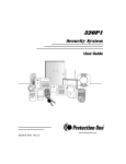
System Overview
Introduction
The Tyco Integrated Security FOCUS CADET is a user-friendly security
system that monitors your site’s detectors and alarms. Fully programmable,
the FOCUS CADET allows you to control hundreds of critical security
functions from one menu-driven interface as simple to use as the automated
teller machine (ATM) at your local bank.
The Tyco Integrated Security FOCUS CADET consists of a central control
unit, an operating panel, and up to 64 protection points. The control unit is
protected by a heavy-gauge steel cabinet and protected by a tamper sensor.
While monitoring protection points 24 hours a day the controller itself is
electronically monitored by trained Tyco Integrated Security personnel. If a
hazard or security breach occurs, the appropriate authorities (police, fire) are
alerted. In case of a maintenance problem, Tyco Integrated Security service
personnel can also be notified.
All functions are accessed through the system operating panels or through
card/key readers.
FOCUS
CADET Features
a. Attractive, easy-to-use, menu-driven operating panel.
b. Control of up to 64 protection points in as many as four independent
groups from one central location.
c. Manual activation or deactivation of any function.
d. Ability to turn group(s) on in either the AWAY or STAY mode. STAY
mode automatically bypasses certain point types. Check with your Tyco
Integrated Security service technician to see if your system contains any
of these point types.
e. Ability to bypass points for maintenance or service.
–3–
System Overview (cont’d)
f.
Capacity of up to 99 individual operating panel users, each having
various security privileges.
g. Capacity of up to 255 individual card/key reader users, each having
various levels of access.
h. Ability to program automatic activation/deactivation of security groups.
i.
Control and recording of employee access to workplace areas along with
time and date.
j.
Recording of security-related activities.
k. Ability to send messages to up to 8 paging services.
Although the FOCUS CADET has many powerful features, Tyco Integrated
Security has designed the system to operate as close to “turnkey” as possible.
Once the FOCUS CADET is set up for your site, operators will need only
swipe or insert a card or key, or enter a six-digit ID code once or twice a day.
Control Unit
The FOCUS CADET control unit – the brains of your security system – is a
powerful microcomputer that manages every function of your security
system. All information about your site’s security is stored in this unit.
The FOCUS CADET operating panel was designed for intuitive and
efficient operation by personnel with little or no experience using security
systems. All operations are accessed through four sequential menus.
The "?" key on each menu provides context-specific help. The QUICK
START section will help even the most instrument-shy operator get up to
speed in under an hour.
–4–
System Overview (cont’d)
Protection Points and Groups
The FOCUS CADET monitors up to 64 protection points in up to four
independent fire and burglary groups. The system lets you designate group
names in ways that make sense for your specific needs. For example, “Office”
and “Warehouse” could cover two sets of entry doors whose alarms
activate/deactivate independently.
Turning groups on and off allows different tasks to be carried out at different
times of day, all while maintaining the optimal level of safety and security.
By scrolling through the FOCUS CADET menu options, you may turn
groups on/off in the AWAY or STAY mode, or bypass points at any time for
maintenance or servicing. The system also allows you to check points or
groups to review their status, and alerts you to the precise location of an
activated alarm. Although some features may be manually activated or
deactivated at any time, FOCUS CADET also features powerful scheduling
capabilities for automated, worry-free operation.
The combination of point/group control and scheduling features allows
operators of the system to construct versatile scenarios quickly and with no
previous programming knowledge.
User Access and Security
NOTE: The Access Control feature is not part of a UL Listed system.
Each FOCUS CADET card/key reader acts as a security gateway to your
workplace, or to a specific area where certain employees have access and
others do not. This feature, which operates on manual-input codes, Wiegand,
proximity, magnetic cards, or Marlok keys, allows tracking of all securityrelated activities, either through a continuous printout or by accessing the
512-event history log. The FOCUS CADET supports up to 255 different
users (maximum 99 user codes, the rest are access cards only) and various
levels of security with all the flexibility you will need to assure that every
employee has the proper level of access to the workplace areas.
–5–
System Overview (cont’d)
Automated Event Recording and Printing
The Tyco Integrated Security FOCUS CADET provides complete
documentation and event-recording capabilities. The system prints all
desired events and stores the last 512 system events in memory. The types of
events recorded in the memory are:
a.
Changes in the
system status.
b.
Activation/deactivati
on of points or groups.
c. Use of a card/key
reader.
d. Modifications to user
or system data.
In addition to the 512-event history log, you may obtain a real-time printout
of all events at a remote printer.
The system’s powerful data-handling capabilities are indispensable for
keeping track of system status, for assuring smooth operation, for verifying
workplace safety and security, and for documenting employee access.
Summary
Tyco Integrated Security’s FOCUS CADET offers the security industry’s
best combination of versatility, value, and ease of use. It handles all your
site’s security and access control needs through a pleasant, intuitive, menudriven user interface. Although the system uses a powerful microprocessor,
it was designed so that non-technical personnel can easily access all its
features.
The QUICK START section is meant as a guide to introduce new users to the
operation of the FOCUS CADET operating panel. After reading QUICK
START and working through the exercises (a process that should take less
than one hour), the user will be familiar with all of the system’s most
important functions and operations. Advanced operations and specific ways
to get the most out of the system are covered in the rest of this manual.
–6–
False Alarm Prevention
Introduction
In recent years the pace of electronic development of security systems has
greatly accelerated. This has brought the price range of reliable monitored
security systems to a level that is affordable to most households and nearly
all businesses. As a result, the number of security systems installed is
expanding swiftly.
Since these security systems are a most significant deterrent to unwanted
intrusion, structures protected by security systems are generally safer than
those without; this is a benefit to both the residents and the local law
enforcement.
However, from time to time, many security system users operate their
system improperly and an alarm signal is generated in error. This situation
is referred to as a “false alarm.”
When a security system monitoring center receives an alarm signal, your
local police and/or fire department will be advised that there is an emergency
at your location requiring their timely response. Even if each user has only
one false alarm every two years, the police could potentially be called upon to
respond to nearly ten million false alarms each year. In most cities, more
than 90 percent of all alarms reported to the police are FALSE! In many
cities, the police spend as much as 15 percent of their time and resources on
false alarm-generated “wild goose chases.” In turn, this:
•
Diverts police and/or fire department personnel from legitimate calls.
•
Puts the community members at unnecessary risk.
•
Wastes taxpayers' money.
•
Embarrasses the security system user.
•
Diverts and wastes security company resources.
–7–
False Alarm Prevention (cont’d)
Statistics verify that more than 75 percent of all false alarms are caused
by alarm system operators
Of these, at least 7 out of 10 are simple errors made by a user while turning
the system on or off or when leaving or entering the building. Other typical
causes are:
1. Entering an area or opening a door or window whose protection has been
turned on.
2. Animals or large insects roaming through areas with protection turned
on.
False alarms on fire-monitored systems are typically caused by burning food,
heavy smoking in a room, or steam from a shower.
Working as a team, you and Tyco Integrated Security must have a goal
of zero false alarms
In many cities, the municipal government and police department are
attempting to make alarm system users more aware of their responsibility to
reduce false alarms by:
1. Requiring permits for alarm system users issued by licensed security
companies.
2. Charging fines for multiple false alarms and, in some areas, escalating
fines if false alarms persist.
3. Refusing to respond to an alarm when the rate of false alarm signals
remains high.
You must help eliminate false alarms
By installing this dependable, state-of-the-art FOCUS CADET system,
which is monitored by Tyco Integrated Security Systems, you have already
taken the first step.
Additional steps are to carefully read and understand this manual, to
become thoroughly familiar with your system by practicing entry and exit
commands, and to learn how your monitoring system can become part of
–8–
False Alarm Prevention (cont’d)
your work-day lifestyle. Learn your Personal Identification Number (PIN),
which is necessary when you communicate with your Tyco Integrated
Security Customer Monitoring Center. Then teach all others who will be
using the system. Make sure they are confident they can flawlessly operate
the system and are able to promptly cancel a false alarm, should one occur.
All users must be very familiar with the operating procedure to cancel false
alarms.
Preventing causes of false alarms
The Tyco Integrated Security brochure entitled Helping You Prevent False
Alarms refers you to this manual for any of several actions you may take to
prevent false alarms. These actions are listed below:
1. When You Test Your System: Follow the procedure under the heading
TESTING THE SYSTEM in this manual. Make certain your system is
“out of service” before you start testing the various sensors.
2. If You Move to a Different Building: Tyco Integrated Security offers a
special consideration to customers who move, provided you give to your
local Tyco Integrated Security representative the name of the party that
purchases or leases your present building. Do not take your operating
panel or any part of your system with you. Ask Tyco Integrated Security
to take your system out of service just before the new party takes
ownership of your present building.
3. If You Get a Watchdog: Nearly all types of animals can cause false
alarms. If you get a watchdog or have other animals, do not allow them
into a room with an area sensor when your system is turned on.
4. If You Hire Janitorial Help: Assign a special user code to each janitor,
and enter the code into the system using the procedure under the
heading SYSTEM PROGRAMMING in this manual. Carefully train your
help to turn the system on, turn it off, and cancel false alarms. They
must also understand the entry and exit delays and be able to respond to
a verification call from your Monitoring Center.
–9–
False Alarm Prevention (cont’d)
5. If You Fumigate Your Building: The chemical fog used in the
fumigation process may be sensed as smoke by fire alarm smoke
detectors and may also adversely affect area sensors. Therefore, be sure
to notify Tyco Integrated Security BEFORE starting.
6. If You Change Your Telephone: Changes in the location of the
telephone outlets or telephone numbers could compromise the
effectiveness of your security system. Have a Tyco Integrated Security
service technician inspect your system immediately after any such
changes.
7. If You Install Anything Near Any System Device: If you install any
electrical or electronic equipment within a few feet of any element of your
security system, it could cause the security equipment to malfunction.
Discuss such installation plans with a Tyco Integrated Security service
technician prior to proceeding with the installation.
8. If You Remodel or Renovate Your Building: During the course of
remodeling or renovating, there are often changes in telephone and/or
electrical circuits. In addition, large clouds of construction dust are
generated. Any of these can compromise the effectiveness of your security
system.
In addition, any change in the position of walls, doors or window
openings may disable certain sensors in your system. A change in the
location of mirrors, pictures, or other wall hangings, as well as fans or
large plants, could cause a false alarm when an area sensor is activated
by movement or reflections of movement.
Remember to discuss any renovation or redecorating with your Tyco
Integrated Security representative before you start construction or
redecorating, and once again when you complete it.
– 10 –
Quick Start
Introduction
The QUICK START section is designed to familiarize new users with the
operation of the FOCUS CADET operating panel in under an hour. It will
introduce you the FOCUS CADET’ four primary menus and guide you
through the logic behind one or two operations from each menu.
Think of the QUICK START section as a “crash course” on how to access
basic menus and functions of your new security system. After reading the
QUICK START section and going through the exercises, users will be better
able to define their particular control and programming needs and to
pinpoint problems, then locate the needed information in this manual and
follow the specific instructions confidently and efficiently.
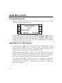
Operating Panel Functions
The operating panel is the primary interface between you, the operator,
and the electronic components forming the “brains” of your FOCUS CADET
security system. The panel consists of a liquid crystal display (LCD) on the
left and a numeric keypad (similar to the buttons on a TouchTone phone) on
the right. Users can access most FOCUS CADET operations through the
LCD. Some operations require both the LCD screen and the keypad.
Operating panel functions are divided into three main groups:
1. Programming — Operations relate to system settings, user names, user
ID numbers, schedules, names of points and groups, and time/date
functions.
2. System — Operations allow you to turn burglary protection on and off,
bypass protection points, respond to system alarms, obtain a history log,
and extend your site’s close time.
3. Test — Operations enable operators to test protection points, security
groups, and hardware.
– 11 –
Quick Start (cont’d)
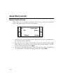
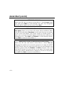
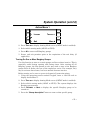
Normal Inactive Screen
When there are no alarms or troubles and no one is using the operating
panel, the Normal Inactive Screen will display:
Front Office
?
Off
More 12:59pm
Clear 1. Press the ? to view the Help Screen, which will aid you in responding to
an alarm or trouble condition.
2. The top line of the display will indicate a particular Burglar Alarm (BA)
group and the second line will indicate that group’s status. To view
status of other BA groups, press More.
3. As you enter your ID code, the system will verify your entry by displaying
“X.” If you make a mistake entering your ID code, press Clear.
– 12 –
Quick Start (cont’d)
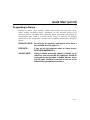
Responding to Alarms
During an alarm, your system’s alarm annunciating devices (bell, siren,
lights, and/or operating panel, depending on the optional devices you
selected) will be activated. The operating panel and horns will sound an
intermittent tone (with a 5-second pause every 10 seconds) to audibly
annunciate a fire alarm and a steady tone to audibly annunciate a burglary
alarm.
BURGLARY NOTE: Do not enter the premises until police arrive. Have a
key available to let the police in.
FIRE NOTE:
If you are on the premises when an alarm occurs,
EVACUATE IMMEDIATELY.
HOLDUP NOTE:
During a holdup or hostage (duress) situation, try to
remain as calm as possible. All employees should be
instructed on the operation of holdup devices. Users
with ID codes should be instructed on the use of the
Ambush/Hostage and Duress features.
– 13 –
Quick Start (cont’d)
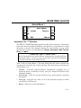
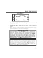
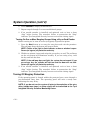
Viewing Current Alarms
During an alarm (excluding holdup, hostage and duress alarms), the
operating panel will display the current alarm by type and point description.
? 1 Fire Alarm
Smoke Detector
NoOther Alarms
Continue
1. Using the operating panel’s numeric keypad, enter a valid ID code to
display the Action Menu 1 (see page 19) if no burglary groups are on; or
press the “Turn off” selector button (if burglary groups are on) to
deactivate all annunciating devices.
2. If burglary groups are on, complete the steps under “Turning Off
Burglary Protection” in the SYSTEM OPERATION section. When all
burglary groups are off, press Continue to display Action Menu 1.
3. Press See alarms to display the alarm type, point number, and
description.
4. Press Prev or Next to display additional alarms.
5. Press Quit to display Action Menu 1.
– 14 –
Quick Start (cont’d)
Entering Your Personal ID Number
The first step in performing any function within the FOCUS CADET
system is to enter your personal six-digit ID number.
EXERCISE: ENTERING A VALID ID CODE
Enter your personal ID number. You should hear a short beep after
each digit is entered. After your number has been accepted, you will
hear a longer beep. Now wait about 15 seconds and try to enter
another, random six-digit number. What happens now? The number is
recognized as an invalid ID code and the operating panel will display
“Code Incorrect, Try Again.” If you make a mistake, press “Clear” to
re-enter the number.
The operating panel is active for 10 seconds after a valid code is entered.
This means you must enter a menu selection within that time or the
operating panel will deactivate, requiring the input of a valid ID code again.
Once you have selected a menu item, however, the panel remains active for a
full minute before becoming inactive. This timeout feature automatically
secures your FOCUS CADET security system in the event of a distraction
or emergency that causes you to step away from the operating panel.
EXERCISE: PANEL ACTIVATION/DEACTIVATION
Enter your ID code. Count to 15 after you hear the long beep. The
operating panel should now become inactive. Enter your ID code
again. As soon as you hear the long beep, press the More selection
once. The screen should change to the next menu, Action Menu 2
(see page 21). Wait a few seconds and press More again. You
should now be on Action Menu 3 (see page 23). Now wait a full
minute. What happens?
– 15 –
Quick Start (cont’d)
If you waited a full minute in the last exercise, your operating panel should
have entered its timeout phase. In other words, you have one minute after
entering your last menu selection before the operating panel shuts down.
Hostage
If this feature has been enabled, you can activate a silent holdup alarm by
entering your ID code and incrementing the last digit by 2. For example, if
your ID code is 011234, enter 011236 instead. Note that an ID code with a
last digit of 8 becomes 0 and a 9 becomes 1.
The Navigational Menu Selections
Each of the four Action Menus has several selections, depending on user
privilege. Among these are the navigational menu selections, which take you
from one menu to the next and back again. The two navigational selections
from these menus are More/First and Quit/Previous.
The More/First Selection
The More selection allows you to scroll through the Action Menus. At the last
menu designation, the More selection changes to First. Selecting First brings
you back to the first Action Menu. The position (bottom right) of the key does
not change.
EXERCISE: THE MORE/FIRST SELECTION
Enter your ID code and press the More selection three times. You are
now at the last Action Menu screen, and the More selection on the
screen has changed to First. Choosing First will now bring you back to
the first Action Menu screen. Repeat the steps two or three times to
verify that you have seen each screen before.
The Quit/Previous Selection
Pressing the menu selection Previous on the bottom left of each Action Menu
screen returns you to the previous Action Menu. Choosing Quit from Action
Menu 1 deactivates the operating panel.
– 16 –
Quick Start (cont’d)
EXERCISE: THE MORE/PREVIOUS SELECTION
Enter your ID code and press the More selection once, then press the
Previous selection. You should be back at Action Menu 1. Now choose
More three times and Previous three times. Again you should be back
at Action Menu 1. Experiment with the More and the Previous
selections until you feel comfortable navigating through the four
Action Menus.
Now return to the Action Menu 1 (choose Previous until its
designation changes to Quit). Choose Quit to return to the inactive
operating panel display.
Other Navigational Selections
Later on, when you begin working in the submenus of the FOCUS CADET
system, you will encounter other navigational selections such as Enter,
Done, Next, Pgdn, and Continue. The first two are used at the end of
operations such as entering a new group name or changing an ID code. Next,
Pgdn, and Continue are specific to certain submenus. Their meaning is
similar to More in the Action Menus (i.e., they move you to the next logical
step in the programming or operational procedure).
Summary: Navigational Selections
Every Action Menu screen contains two navigational selections, More/First
and Quit/Previous. More/First allows you to scroll forward among the four
Action Menus, while Quit/Previous brings you to the previous menu screen
(from screen 2-4) or inactivates the operating panel (from screen 1). If you
are not completely comfortable with the navigational selections, go back and
repeat the exercises before continuing.
– 17 –
Quick Start (cont’d)
Turning BA Groups Off
When an ID code is entered and any BA (Burglary) group is on, you will be
presented with the following screen:
Some BA Groups
are on
Code Accepted
Continue
Turn Off
If you desire to turn off any group, press Turn Off to display groups that are
on. To scroll through the groups that are on, press Previous or Next. To turn
off that group, press the key to the right of the group name. Hint: If all BA
groups you have access to are to be turned off, press All. Repeat the previous
steps for all groups to be turned off.
Action Menus 1-4 – Main Features
Now that you are familiar with the navigational and help features common
to all FOCUS CADET menus, it’s time to take a closer look at what
distinguishes one menu from another. To perform all the exercises here, your
ID code will need to have access to all levels of operation.
Operating panel Action Menus 1-4 give you access to all the features in your
security system through just 14 feature selections (three each on Action
Menus 1 and 2, four each on Action Menus 3 and 4). These 14 selections, in
turn, lead you logically and intuitively through the system submenus.
The FOCUS CADET operating panel was designed to maximize
functionality while eliminating memorization of complex commands; one
menu leads you to the next — and the next, if necessary — until your
operation is complete.
– 18 –
Quick Start (cont’d)
Action Menu 1
?
Lesson
Quit
Enter choice:
Turn on More Assistance: The “?” Selection
The FOCUS CADET operating panel provides online assistance. Choosing ?
from most menus provides definitions, descriptions, and assistance in using
that menu or screen. For example, choosing ? at Action Menu 1 gives online
descriptions of choices corresponding to Lesson, See alarms, Quit, Turn on,
Reset, and More.
EXERCISE: THE “?” SELECTION
Scroll through the four Action Menus using the two navigational keys
discussed earlier. At each screen, choose the ? selection to familiarize
yourself with the various Help Screens.
Take a look at Action Menu 1. You now know that this menu contains two
navigational selections and a help selection. The four feature selections for
Action Menu 1 are:
•
Lesson – Provides context-sensitive information regarding use of
operating panel, availability of help, and Tyco Integrated Security help
telephone number.
•
See alarms – Lists all current alarms by type, point number, and point
description.
•
Turn on – Activates one, some, or all of the protection groups in either
the AWAY or STAY mode.
•
Reset – Takes you to Reset Submenu 1.
– 19 –
Quick Start (cont’d)
EXERCISE: LESSON
Enter your ID code and observe Action Menu 1. Press Lesson. Read
text, then press More to scroll through text. Note Tyco Integrated
Security phone number on last screen. Press Quit.
EXERCISE: SEE ALARMS
See alarms allows you to review all current alarm conditions. Enter
your ID code and choose See alarms. At this time there are no alarms,
so the screen will display “No current alarms or trouble points.” If
there were, an alarm or trouble display would show the condition and
description of it. Press Next and Previous to scroll through alarms.
Press Quit to return to Action Menu 1.
EXERCISE: TURN ON BURGLARY PROTECTION
Enter your ID code and observe Action Menu 1. Press Turn on.
Choosing this enables you to turn the group(s) on in either the AWAY
or STAY mode. Once you select the mode, you can scroll through your
burglary groups using the Previous and Next selections. Try it. To
turn specific groups on, press the key to the right of the group name
when that group’s identification is displayed. To turn on all groups,
press All. Press Quit to return to Action Menu 1.
– 20 –
Quick Start (cont’d)
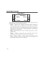
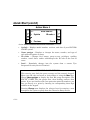
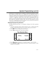
Action Menu 2
?
See points
Enter choice:
Test Previous
More Action Menu 2 has three feature selections:
•
See points – Displays the number, description and current status of
each protection point.
•
Change close time – Changes the close (system on) time of protection
groups.
•
Test – Takes you to the Test Submenu for testing of protection groups,
points, holdup devices, and/or the bell and display.
EXERCISE: SEE POINTS
From Action Menu 2, choose See points to enter a submenu. Press
Supervisory, Burglary, Holdup, or Fire (depending on services being
provided). If Burglary is selected, select which group. Press Installed.
This will show you the first point of the selected service. If there is
more than one point in this service, press Next to see the next point.
NOTE: Next and Previous will not be displayed if there is only one
point in that service. Press Quit to return to Action Menu 2.
EXERCISE: TEST
The test function is used for testing points, groups, and alarm
functions of your security system. To explore this function, enter your
ID code and enter Action Menu 2 by pressing More at Action Menu 1.
Press Test to go to the Test Submenu. Press More to display Test
Submenu 2. Press Quit to return to Action Menu 2.
– 21 –
Quick Start (cont’d)
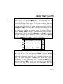
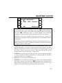
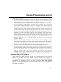
Action Menu 3
?
Bypass
Previous
Enter choice:
History
More Action Menu 3 is your starting point for most time-related, power status, and
bypass functions. It has four feature selections:
– 22 –
•
Bypass – Bypasses and unbypasses protection points, displays the
number of points within each group that can be bypassed, or bypasses
Vault Vibration Sensor points. Bypassing a point causes the system to
ignore that point until it is restored to normal operation (unbypassed).
Bypassing may be used to ignore a malfunctioning device, such as repair,
maintenance, or construction.
•
Status – Checks status of AC power, standby battery power, and the
telephone line.
•
History – Displays or prints the most recent 500 system events,
including user, time, and date of the occurrence of each event.
•
Time – Displays, modifies, or enters time-related functions such as
holidays, open/close schedules, daylight savings, current time/date, and
the open/close schedule in case of an ambush.
Quick Start (cont’d)
EXERCISE: BYPASS/UNBYPASS PROTECTION POINTS
Enter your ID code and press More twice to display Action Menu 3.
Choosing Bypass leads you to the Bypass selection menu. (You must
have a Bypass BA privilege. If not, you will not see Bypass). Selecting
Burglar will bring you to the Group Selection menu for the BA groups.
You may now scroll through the list of your burglary groups using the
Previous and Next selections. (This is automatically skipped if only
one BA group is being used). Choose one of the groups and press the
key next to the name of the group to display the Bypass Submenu.
Choose Bypass points to display point number, status, description,
and additional selector keys. Use Previous and Next to navigate
through a listing of specific points. To choose a point, press Bypass.
(Notice that Bypass changes to Unbypass.) Unbypass that point by
pressing Unbypass. Press Quit to return to Action Menu 1.
?
Bypassing:
Bypass points Quit
Bypass VVS EXERCISE: HISTORY LOG
Enter your ID code and scroll to Action Menu 3. To display the last
500 events by date, time and type, press History and select On this
screen. The most recent event is displayed first. PgDn displays
additional information about an event, including the user name,
point, and group descriptions. PgUp returns you to the original
information. To scroll through the events, use Prev and Next. At any
time you may select Quit to return to the History Selection Menu. To
obtain a hard copy of the history log, select On printer from this
menu. Pressing Quit again will return you to Action Menu 1.
– 23 –
Quick Start (cont’d)
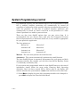
Action Menu 4
?
SysInfo
Previous
Enter choice:
ID codes First Action Menu 4 contains four feature selections:
•
SysInfo – Displays model number, revision, and date of your FOCUS
CADET system.
•
Name pnt/gps – Displays or changes the name, number, and type of
each protection point or group.
•
ID codes – Changes user names, group access, privileges, card/key
number, cancel dates, and/or adds/changes the ID code of the first 99
users.
•
Load – Downloads changes into the system from a remote Tyco
Integrated Security Service Terminal.
EXERCISE: NAME PNT/GPS
This exercise uses both the menu screens and the numeric keypad.
Enter your ID code and scroll to Action Menu 4 using the More key.
Choose Name pnt/gps to display the first BA group description. The
FOCUS CADET lists the groups first, then card/key readers, then
points. If you are familiar with your protection point ID numbers, you
may go directly to a point by entering its corresponding three-digit
number on the keypad.
Pressing Change now displays the selector keys for entering a new
description for a point or group from the Character Entry Screen.
– 24 –
Quick Start (cont’d)
? FIRST BA GROUP
Back
Quit
CHR
Forward Continue The first line of the screen displays the current name with the cursor
on the first letter of the description. Use the POS (Cursor Position)
keys to move the cursor to the right and left through the description.
Use the CHR (Character) keys to scroll forward and backward
through the character list (letters, numbers, symbols, and spaces).
Similarly, you may change characters directly by using the
alphanumeric keypad, which is organized like the TouchTone dial on
a telephone.
Experiment with the alphanumeric keypad. The keypad allows you to
insert a character, space, number, or symbol at any location within
the group, point, or user name:
•
Letters are entered by pressing the key corresponding to them on the
keypad. Pressing a key once, twice, or three times enters the first,
second, or third letter shown on the button. For example, press the 5
key three times to enter the letter L. The letters Q and Z are the
fourth letters for the 7 and 9 keys, respectively.
•
Numbers are entered by pressing the 0 key once to enter the number
0, or by pressing the 0 key repeatedly to scroll through the numbers
until the correct one is displayed.
•
Spaces are entered by pressing the 1 key.
•
Symbols are accessible by pressing the 1 key and scrolling through
the entire character set using the CHR (backward and forward) keys.
Hint: Scrolling through the entire alphabet will take less time if you
hold the keys down instead of pressing and releasing them.
– 25 –
Quick Start (cont’d)
Summary
After reading through the Quick Start section and going through the
exercises, you should be familiar with the operating panel of the FOCUS
CADET security system. If you are uncertain of any operation, return to that
part of this section and repeat the exercise.
– 26 –
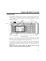
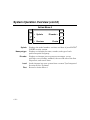
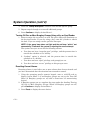
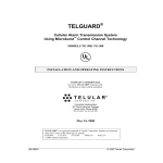
System Operation Overview
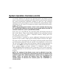
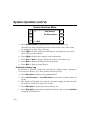
Operating Panel
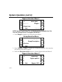
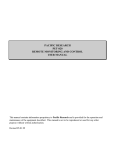
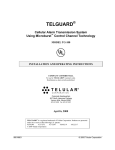
Your FOCUS CADET security system is controlled through interactive
operating panels consisting of a numeric keypad for entering data; a fourline, 17-character (per line) display; and 8 selector buttons for choosing
operating functions.
Numeric Keypad
Selector Buttons
Help Button
1
4
GHI
7
PRS
2
ABC
5
JKL
8
TUV
3
DEF
6
MNO
9
WXY
0
Display Screen
Operating Panel
Your “key” to the system is your personal 6-digit identification code, which
provides access to all operating functions. The system can be programmed to
limit the operational capabilities of each ID code and user.
As each digit of an ID code is entered from the numeric keypad, the
operating panel will emit a short beep. When the final digit of a valid ID code
is entered, the operating panel will emit a longer beep, signifying the ID code
was accepted.
NOTE: If you enter 18 incorrect digits, the operating panel will go into
“lock-out,” preventing further entries for 60 seconds.
– 27 –
System Operation Overview (cont’d)
As selector buttons are pressed, the operating panel will display system
status, selection menus, prompts, and help screens to guide the user through
the various operational capabilities assigned to that user. The messages
displayed on the operating panel can be customized by programming unique
descriptions for the name of each protective point, group of protective points,
holiday, and users.
NOTE: The operating panel remains “active” for 10 seconds after the entry
of a valid ID code. However, pressing a selector button within the initial 10
seconds extends the “active” period to 60 seconds.
Upon entry of a valid ID code, the operating panel will display the first of
four Action Menus. These Action Menus display all the operating functions
the user can access. To choose a displayed function, simply press the
corresponding selector button.
If you encounter a problem or require additional information during the
operation of the system, simply press the Help button located in the upperleft corner of the operating panel. The display will then provide instructions
and information associated with the specific items displayed on the screen.
The use of the "Help" button will not interfere with the system operation in
process. Press Quit or the upper-left button again to exit the Help display.
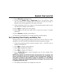
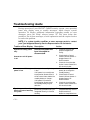
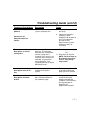
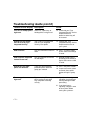
If a system trouble or error message is displayed, refer to the
TROUBLESHOOTING GUIDE section. It provides a list of these messages,
a brief explanation of each message, and the required action to resolve the
problem.
NOTE: The contrast of the display screen can be adjusted at any time.
Simply press the [0] and [#] keys simultaneously which are located on the
numeric keypad. The contrast adjustment options will be shown on the
display screen. To increase the contrast, press the “CONTRAST (+)”
selector button. To decrease the contrast, press the “CONTRAST (-)”
selector button.
– 28 –
System Operation Overview (cont’d)
Action Menus
Upon the entry of a valid ID code, the operating panel will display the first of
four Action Menu screens. These menus are the starting point for all
operating functions that can be accessed (except turning off the system). To
choose a displayed function, simply press the corresponding selector button.
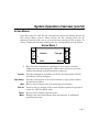
Action Menu 1
?
Lesson
Quit
Enter choice:
Turn on More ?
Help. Provides information regarding all other items currently
displayed on the operating panel. Help can be selected at any time
without interfering with the operation in process.
Lesson
Provides information regarding use of the operating panel and the
availability of Help messages.
See alarms
Provides a description of all current alarms by type, point number,
and point description.
Quit
Turn on
Reset
More
Exits a menu or deactivates the operating panel display.
Turns on all or a portion of the system burglary protection groups in
either the AWAY or STAY mode.
Resets (clears) alarms and test modes.
Displays the next Action Menu, more information, or additional
operating functions.
– 29 –
System Operation Overview (cont’d)
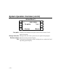
Action Menu 2
?
See points
Enter choice:
Test Previous
More See points Displays the number description and current status of each
protection point.
Change close time Changes the close time (system on) of a protection group(s).
Previous or Prev Returns to the previous display.
Test Tests protection groups, points, holdup devices, and/or bell and
operating panel display.
– 30 –
System Operation Overview (cont’d)
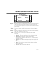
Action Menu 3
Bypass
Status
History
Time
?
Bypass
Previous
Enter choice:
History
More Bypasses (ignores) or unbypasses (restores to normal operation)
protection points, displays the number of points within each
group that can be bypassed, or bypasses Vault Vibration Sensor
(VVS) points.
Checks AC power, standby battery power, and the telephone
line.
Displays or prints the 500 most recent system events including
user, time, and date for each event.
Displays, enters, or changes the following time-related
functions:
•
Holiday – The name and date of each scheduled holiday.
•
Open/Close – Temporary and permanent daily
opening/closing schedules and limits (i.e., earliest opening
and latest closing).
•
Daylight – The dates of daylight savings time (spring and
fall).
•
Hstg – The open/close schedule for an ambush condition
(forced open/close).
•
Current – The current time and date.
– 31 –
System Operation Overview (cont’d)
Action Menu 4
SysInfo
Name pnt/gps
– 32 –
?
SysInfo
Previous
Enter choice:
ID codes First Displays the model number, revision, and date of your FOCUS
CADET security system.
Displays or changes the name, number, and type of each
protection point and group.
ID codes
Displays or changes user or group access names, access
privileges, user card/key numbers, the user ID code of the first
99 persons, and cancel dates.
Load
Loads changes into your system from a remote Tyco Integrated
Security Service Terminal.
First
Return to Action Menu 1.
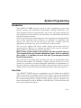
System Programming
Introduction
Your FOCUS CADET security system is easily customized to meet your
specific security and monitoring requirements. During installation, your
Tyco Integrated Security representative will review all system options and
will recommend certain features and functions to accommodate your facility
and daily business routines.
Certain system features and functions can be reprogrammed (changed) from
your remote operating panel. However, to program or reprogram your
system, you must use an ID code that has been assigned with the
appropriate “privilege level” (see User Data later in this section).
You can enter, display, add, delete, and/or change system data from your
operating panel. However, as changes are made, keep accurate and up-todate records to avoid potential errors in the future.
NOTE: Certain system features and functions must be controlled from the
Tyco Integrated Security Customer Monitoring Center. Prior to modifying
your system, it is advisable to check with your Tyco Integrated Security
Service Representative.
Your interactive operating panel provides four lines of information and/or
messages that prompt you through a simple selection process. If you are
unsure of a procedure, or require additional information or explanation of a
feature or function, simply press the "Help" selector button. You can use the
"Help" button at any time without interfering with the operation in process.
User Data
Your FOCUS CADET system accommodates up to 99 different six-digit ID
codes. Users must be assigned an ID code in order to access the operating
panel. The first two digits represent the user number. The last four serve as
the Personal Identification Number (PIN), which uniquely identifies the
person operating the system. Without a valid ID code, a user will not be able
to access or operate the system.
– 33 –
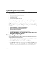
System Programming (cont’d)
Once an ID code is assigned to a user, that user may automatically perform the
following functions:
•
Turn on/off assigned Burglary Protection.
•
Test system sounders.
•
Test burglary points.
•
View/print the system’s history log.
Each code may also be assigned a specific “Privilege Level(s)” that provides
access to additional system operating functions (see Assigning Privilege Levels
later in this section). If a user does not have the privilege to operate a function, it
will not be displayed as a selection choice.
NOTE: Upon installation or initial system setup, one user (e.g., System
Manager) will be assigned the “Privilege Level” to perform the following
functions:
•
Open outside of the schedules (Irregular open).
•
Bypass burglar alarm (BA) protection points.
•
Change temporary schedules.
•
Change permanent daily schedules and the real-time.
•
Change, add, and delete user names, ID codes, card/key codes, cancel
dates, and “Privilege Levels” for users.
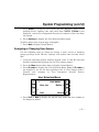
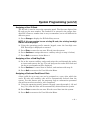
Entering or Changing a User Name
Use the following procedure to add new users, change an existing user's access,
or delete existing users from the system.
1. Using the operating panel’s numeric keypad, enter a valid ID code that has
been assigned the privilege level of "Can change names."
2. Press the More button three times to display Action Menu 4.
3. Press ID codes to display the User Selection Menu. NOTE: If ID codes is not
displayed, you do not have the privilege level of "Can change names."
Consult your manager or Tyco Integrated Security Service Representative.
– 34 –
System Programming (cont’d)
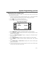
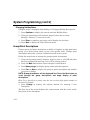
User Selection Menu
?
User xxx
Quit
User Name
Delete Next 4. Press Prev or Next to display the specific user name and user number to
be changed or added.
Hint: To go directly to the user, enter one-to three-digit user number on the
numeric keypad.
5. Press Change to display the Character Entry Screen to change the user
name.
The first line of the screen displays the current name with the cursor on the
first letter of the description.
6. Use the POS (Cursor Position) keys to move the cursor to the right and
left through the description. Use the CHR (Character) keys to scroll
forward and backward through the character list (letters, numbers,
symbols, and spaces).
Similarly, you may change characters directly by using the alphanumeric
keypad, which is organized like the TouchTone dial on a telephone.
•
Letters are entered by pressing the key corresponding to them on the
keypad. Pressing a key once, twice, or three times enters the first,
second, or third letter shown on the button. For example, press the 5 key
three times to enter the letter L. The letters Q and Z are the fourth
letters for the 7 and 9 keys, respectively.
•
Numbers are entered by pressing the 0 key once to enter the number 0,
or by pressing the 0 key repeatedly to scroll through the numbers until
the correct one is displayed.
– 35 –
System Programming (cont’d)
•
Spaces are entered by pressing the 1 key.
•
Symbols are entered by pressing the 1 key, then using the CHR
(backward and forward) keys to scroll through the entire character set.
Hint: Scrolling through the entire alphabet will take less time if you hold
the keys down instead of pressing and releasing them.
7. Press Continue to display the User Selection Menu again.
Repeat steps 4 through 6 to change the name of other users.
8. Press Quit to display Action Menu 4.
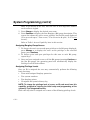
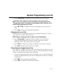
Deleting a User ID Code
Use this function to eliminate a user’s access to the security system.
1. Using the operating panel’s numeric keypad, enter a valid ID code that
has been assigned the privilege level of "Can change names."
2. Press the More button three times to display Action Menu 4.
3. Press ID codes to display the User Selection Menu. Note: If ID codes is
not displayed, you do not have privilege level of "Can change names."
Consult your manager or Tyco Integrated Security Service
Representative.
User Selection Menu
?
User xxx
Quit
User Name
Delete Next 4. Press Prev or Next to display the specific user name and user number to
be deleted.
Hint: To go directly to the user, enter the one- to three-digit user number
on the numeric keypad.
– 36 –
System Programming (cont’d)
5. Press Delete to delete the User Name, ID code, Burglary group access,
privilege levels, card/key code, and cancel date. NOTE: If Delete is not
displayed, contact Tyco Integrated Security for removal of this user from
the system.
6. Press Continue to display the User Selection Menu again.
To delete other users, repeat steps 4 through 6.
7. Press Quit to display Action Menu 4.
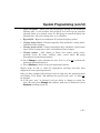
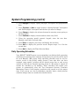
Assigning or Changing User Access
Use the following steps to assign or change a user’s access to burglary
groups, privilege levels, ID code, card/key code, and/or code and card cancel
date.
1. Using the operating panel’s numeric keypad, enter a valid ID code that
has been assigned the privilege level of "Can change names."
2. Press the More button three times to display Action Menu 4.
3. Press ID codes to display the User Selection Menu. Note: If ID codes is
not displayed, you do not have privilege level of "Can change names."
Consult your manager or Tyco Integrated Security Service
Representative.
User Selection Menu
?
User xxx
Quit
User Name
Delete Next 4. Press Prev or Next to display the specific user name and user number to
be changed or added.
– 37 –
System Programming (cont’d)
Hint: To go directly to the user, enter the one- to three-digit user number
on the numeric keypad.
5. Press Change to display the desired user name.
6. Press Continue to display the first Burglary (BA) group description. This
screen also shows the user’s access privilege for the BA group displayed
("Can access & open," "Can access," "Can access irr & open," or "Can not
access").
Refer to Table 1: Access Capability later in this section.
Assigning Burglary Group Access
7. To change the user’s access and open privilege to the BA group displayed,
press Change or to display the user’s access privilege to the next BA
group, press Continue.
8. To assign access and open privileges for this user to each BA group,
repeat step 7.
9. Once you have assigned access to all the BA groups (pressing Continue at
the last BA group), the operating panel will automatically display the
Privilege Level Selection Menu.
Assigning Privilege Levels
Once an ID is assigned the user may automatically perform the following
basic functions:
•
Turn on/off assigned burglary protection.
•
Test system sounders.
•
Test burglary points.
•
View/print the system’s history log.
NOTE: To change the privilege level of a user, an ID code must have this
capability assigned to it during the initial setup and programming of the
system by Tyco Integrated Security.
Each code may also be assigned one or more of the following privilege levels:
– 38 –
System Programming (cont’d)
•
Open irregular – Open (turn off) BA group(s) outside of the scheduled
opening time. A user without this privilege level will trip an irregular
opening alarm or be denied access if a BA group is turned off before the
opening time, after the closing time, or on a holiday.
•
Bypass BA – Bypass and unbypass all assigned burglary points.
•
Change temp sched – Change temporary daily schedules, closing times,
and limited time changes.
•
Change perm sched – Change permanent daily schedules, earliest open
times, latest closing times, date, and unlimited time changes.
•
Change names – Add, change or delete user names, group access,
privilege levels, ID codes, card/key codes, cancel dates, BA group
descriptions and point descriptions.
10. Press Change to select whether the user “Can” or “Can not” perform the
operating function displayed.
11. Press Continue to move to the next operating function.
Repeat steps 10 and 11 until the appropriate privilege level has been
assigned for each operating function.
Once you have assigned all privilege levels for this user, the operating panel
will display “User Name” and whether the user ID code “may” or “may not”
be changed.
12. If the user “may” be changed, and you desire to change or assign the
user's ID code, press Change and continue with step 13. Otherwise, press
Continue and skip to step 18.
– 39 –
System Programming (cont’d)
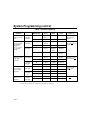
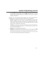
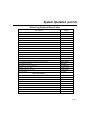
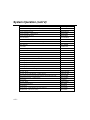
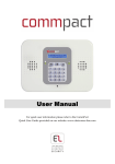
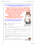
Table 1: Access Capability
Access
Capability
Time
Condition of
BA Group(s)
Access
Action
CMC
Signal
Log and
Print
Programming
Required
Person can open
and access any
time.
Inside or
Outside
Schedule
On
Open and
Access
Opening
Opening
Off
Access
No Signal
Access (1)
Access irr & open
plus can open
irregular
Same as above,
but an irregular
event will be
flagged for
access outside
of schedule
(PVF).
Inside
Schedule
On
Open and
Access
Opening
Opening
Off
Access
No Signal
Access (1)
On
Open and
Access
Irregular
Opening
(PVF)
Irregular
Opening
Off
Access
No Signal
Irregular
Access
On
Open and
Access
Opening
Open and
Access
Off
Access
No Signal
Access (1)
On
No Access
No Signal
No Access
Off
No Access
No Signal
No Access
Person can open
and access, but
only within
schedule.
Outside
Schedule
Inside
Schedule
Outside
Schedule
(2)
Person cannot
open, but can
access within
schedule.
Person cannot
gain access at
any time.
Inside
Schedule
Outside
Schedule
(2)
Inside or
Outside
Schedule
On
No Access
No Signal
No Access
Off
Access
No Signal
Access (1)
On
No Access
No Signal
No Access
Off
No Access
No Signal
No Access
On
No Access
No Signal
No Access
Off
No Access
No Signal
No Access
NOTES: 1. Nothing will be logged or printed if the Log Option = N. Selectable for each reader.
2. Access can be granted by establishing a temporary schedule.
– 40 –
Access irr & open
Plus can not open
irregular
Can access &
open plus can not
open irregular
Can access plus
can not open
irregular
Can not access
System Programming (cont’d)
Assigning a User ID Code
The ID code is used to access the operating panel. The first two digits of the
ID code are the user number. The number to be entered is the unique fourdigit PIN. Choose a number that is easy to remember, but is still difficult for
others to guess.
13. Press Change to display the ID Code Entry screen.
NOTE: If this user number has an existing ID code, the existing four-digit
PIN will not be displayed.
14. Using the operating panel’s numeric keypad, enter the four-digit user
PIN. Each digit is displayed as entered.
15. Press Enter to enter the new user ID code into the system.
16. Press Continue to assign this user a card/key code (go to step 18 below).
17. Press Quit to return to Action Menu 4.
Assigning a User a Card/Key Code
18. Go to the nearest card/key reader and swipe the card through the reader
or insert and remove the key. The red lamp on the reader will flash and
the key or card number will be displayed.
19. Press Continue if a cancel date is desired, and continue with step 21.
20. Press Quit to return to the User Selection Menu.
Assigning a Code and Card Cancel Date
A date valid for up to one year can be assigned to a user, after which the
user’s ID code and card/key code will be automatically deleted from the
system. Use this feature only for temporary help or construction personnel
who will not need access after a job is completed.
21. Using the operating panel’s numeric keypad, enter the month (1-12) and
day (1-31) that this user will be automatically deleted from the system.
22. Press Enter to enter the new user ID code cancel date into the system.
23. Press Quit to return to the User Selection Menu.
– 41 –
System Programming (cont’d)
Changing the Time and Date
Your FOCUS CADET security system contains a real-time clock and
calendar, which must be programmed at the time of installation. Periodically
check the clock and calendar to ensure their accuracy. The time and date
may require re-entering if both AC power and battery power have been
interrupted or disconnected. If a change is required, complete the steps
below.
Changing the Current Time
Note: Before changing the time or date, turn off all BA groups.
1. Using the operating panel’s numeric keypad, enter a valid ID code that
has been assigned the privilege level of "Change perm sched" or "Change
temp sched."
2. Press More twice to display Action Menu 3.
3. Press Time to display the Time Selection Menu.
Time Selection Menu
? Time:
Holiday
Quit
Daylight Current 4. Press Current to display the current time and date settings of the system.
5. Press Change to display the selector buttons “Change time” and “Change
date.”
NOTE: Change will not appear unless all BA groups are off.
– 42 –
System Programming (cont’d)
6. Press Change time to display the time currently set in the system.
7. Using the operating panel’s numeric keypad, enter the new time.
NOTE: Those users who have been assigned only the privilege level of
“Change temp sched” are limited to time changes within 5 minutes of the
current time displayed on the screen.
8. Press AM or PM to complete your entry and display the new time and
date.
9. Press Quit to display the Time Selection Menu.
Changing the Current Date
Perform the first 5 steps under the previous heading Changing the Current
Time and then continue with step 6 here.
NOTE: Before changing the time or date, turn off all BA groups.
6. Press Change date to display the date currently set in the system.
7. Using the operating panel’s numeric keypad, enter the new date.
Example: October 7th, 1998 is entered as 100798.
8. Press Enter to complete your entry and display the new date and time.
9. Press Quit to display the Time Selection Menu.
Setting Dates for Daylight Saving Time
Your FOCUS CADET security system will automatically adjust the realtime clock for daylight saving time on the two dates programmed into the
system. To program those dates do the following:
1. Using the operating panel’s numeric keypad, enter a valid ID code that
has been assigned the privilege level of "Change perm sched" or "Change
temp sched."
2. Press More twice to display Action Menu 3.
3. Press Time to display the Time Selection Menu.
– 43 –
System Programming (cont’d)
4. Press Daylight to display “Spring Daylight” description and programmed
date.
5. Press Previous or Next to toggle between “Spring Daylight” description
and “Fall Daylight” description and the date you want to change.
6. Press Change to display the selector buttons for entering a new spring or
fall description.
7. Press Continue to display current and new date entry field.
8. Using the operating panel’s numeric keypad, enter the new date.
Example: April 9th is entered 0409.
9. Press Enter to complete your entry and display the new date.
10. Press Quit to display the previous screen. Repeat steps 5 to 9 for the
second date.
11. Press Quit to display the Time Selection Menu.
Daily Operating Schedules
Your FOCUS CADET system can accommodate two distinct daily operating
schedules (two opening times and two closing times) for each day of the week
for each Burglary (BA) group. Daily operating schedules may be used to
restrict access to the facility and/or system. Users who have not been
assigned “open regular” privilege will be denied access (key or card access
control) or will trip an irregular opening alarm if a BA group is turned off
outside the schedules or on holidays. These schedules also enable your
system to automatically alert the Tyco Integrated Security Customer
Monitoring Center if the burglary protection was turned on at the proper
time. Your system can also accommodate schedule limits, which prevent
schedule changes that are outside the schedule limits.
– 44 –
System Programming (cont’d)
Schedules can be permanent or temporary. A permanent schedule is fixed,
and remains in effect until it is changed (by an authorized user). A
temporary schedule will override the permanent schedule for one day only. It
is automatically deleted at midnight of the day it took effect. For example, on
a Friday, a temporary closing time of 8:00 PM is programmed into the
system to override the permanent schedule closing time of 5:00 PM. It will
affect that day’s (Friday’s) schedule only. The 8:00 PM temporary closing
time will be automatically deleted at midnight, thus restoring the permanent
closing time of 5:00 PM for future Fridays.
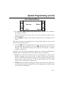
Changing Daily Operating Schedules
Use the following procedure to re-program (change) the daily operating
schedules.
1. Using the operating panel’s numeric keypad, enter a valid ID code that
has been assigned the privilege level of "Can change perm schedule."
2. Press More twice to display the Action Menu 3.
3. Press Time to display the Time Selection Menu.
Time Selection Menu
? Time:
Holiday
Quit
Daylight Current 4. Press Open/close to display the “Group Description” selector button.
5. Press Previous or Next to display the desired “Group Description” of the
schedule to be changed.
– 45 –
System Programming (cont’d)
6. Press the Group Description button to display the selector buttons "Daily
schedules" and "Schedule limits."
7. Press Daily schedules to display the selector buttons "Permanent" and
"Temporary."
8. Press Permanent or Temporary to display the current permanent or
temporary open/close schedule.
Hint: The system will start display with “today” (Mon-Sun).
9. Press More to step through the daily schedules and to the specific daily
schedule you would like to change.
10. Press Change to display the selector buttons "Open time" and "Close
time."
11. Press Open time or Close time to display the open or close schedule entry
screen.
12. Using the operating panel’s numeric keypad, enter the new open or close
time.
Example: 8:22 is entered as 0822.
13. Press AM or PM to complete your entry and to display the new open or
close schedule.
If Auto On/Off feature has been selected, see Changing Auto On/Off
Schedule.
14. Press Change to display the Auto On/Off options, or press Quit to display
another daily operating schedule.
Guidelines for Changing Daily Operating Schedules:
•
•
•
– 46 –
UUUU indicates Unscheduled; enter desired time. NNNN indicates Not
changeable; the schedule cannot be changed. Refer to your master system user.
Open times cannot be later than closing times. Closing times cannot be earlier
than open times.
Pressing Delete when changing an opening time will tell the system that no
opening will occur for that schedule. Persons without irregular access privilege
will be denied access or will create an Irregular Open Alarm.
System Programming (cont’d)
Guidelines (continued):
• Pressing Delete when changing a closing time will tell the system that no closing
will occur for that schedule that day (up to midnight). Use this to tell the system
when there is an early morning closing the next day. You must also program a
12:00 AM opening and a closing time (i.e., 3:00 AM) the next day.
• If your schedule is unpredictable, you may need to program a No Close time
period. Upon opening the group, a timer can be preset with a number of hours
and minutes you will be open that day. A closing timer will start when 20
minutes remain. A closing warning will start when only 5 minutes remain. If the
warning and reminder are ignored, and the group is not closed, a No Close signal
will be sent to the Tyco Integrated Security Customer Monitoring Center. To
program a No Close time, first select the second schedule for the desired day.
Second, delete the second opening time by pressing Change, Open time, Delete.
Third, enter the number of hours and minutes you will be open on that day as the
second closing time. For example, if you want two hours and 30 minutes, press
Change, Close time, 0, 2, 3, 0, AM. Repeat the procedure for each day that this
feature is desired.
• AM is used for less than 12 hours. If 12 to 24 hours is desired, subtract 12 hours
from the desired length of time, enter the remainder, and press PM. For example,
if you want 14 hours and 20 minutes, press Change, Close time, 0, 2, 2, 0, PM.
• The No Close time will take effect only when the group is opened. If you want the
new time to take effect NOW, first turn on the group and then turn it off.
• The programming of the first schedule for each day is optional. If you do program
the first schedule, openings outside the schedule can be restricted. For example, a
first schedule opening time of 5:00 AM and a first schedule close time of 10:00
PM may restrict certain users from midnight to 5AM and from 10PM to
midnight. Persons who open anytime will be required to close the group in the
specified time period entered in the second close schedule as specified above.
Changing Auto On/Off Schedule
Your FOCUS CADET security system can accommodate an Auto On/Off
feature. If enabled, the Auto On/Off feature enables your system to
automatically turn itself on and off according to the daily operating schedule
(permanent or temporary) that you have assigned. The Auto On/Off
feature is automatically deleted on holidays and can be cancelled by
deleting a schedule.
– 47 –
System Programming (cont’d)
For maximum security, the Auto On/Off feature is not recommended. If Auto
Off is enabled, burglary protection will automatically be turned off
regardless of unforeseen events, possibly allowing unauthorized personnel to
enter the premises. If Auto On is enabled, burglary protection will
automatically be turned on, which could lead to the generation of a false
alarm if personnel are within a protected area.
There are four Auto On/Off options that you may select from. It is
recommended that you discuss these with your Tyco Integrated Security
Service Representative to determine which one, if any, would be appropriate
for your particular application.
The four options are:
Manual on
Manual off
Automatic off
Manual on
Automatic on
Manual off
Automatic on
Automatic off
Manual: The user must perform the on/off function.
Automatic: The system automatically performs the on/off function.
The Auto On/Off feature is separately programmed for each group and daily
operating schedule. For example, you can select Auto Off for Burglary Group
1 on Saturday and Sunday only.
If your system was programmed with the Auto On/Off feature at the time of
installation, simply follow the steps under Changing Daily Operating
Schedules. Once you have entered AM or PM at step 13, the display will
indicate whether the system can or cannot turn itself on or off at that time.
15. Press More to display the next daily operating schedule to be changed; or
press Quit to display the Time Selection Menu.
– 48 –
System Programming (cont’d)
Changing Open/Close Schedule Limits
Use the procedure below to change the earliest open times and the latest
close times for the system.
1. Using the operating panel’s numeric keypad, enter a valid ID code that
has been assigned the privilege level of "Can change perm sched."
2. Press More twice to display Action Menu 3.
3. Press Time to display the Time Selection Menu.
Time Selection Menu
? Time:
Holiday
Quit
Daylight Current 4. Press Open/close to display “Group Description” selector buttons.
5. Press Previous or Next to display the desired “Group Description” of the
schedule to be changed.
6. Press the “Group Description” button to display the “Schedule limits”
selector button.
7. Press Schedule limits to display the limits currently set in the system.
8. Press Change to display selector buttons "Earliest open" and "Latest
close."
9. Press Earliest open or Latest close to display the current earliest open
and latest close time.
10. Using the operating panel’s numeric keypad, enter the new earliest open
or latest close time (enter hours only).
– 49 –
System Programming (cont’d)
11. Press AM or PM to complete the entry and to display the new schedule
limits.
12. Press Change to re-enter an earliest open or latest close time, or press
Quit to display other schedule options.
Holiday Description and Dates
Your FOCUS CADET security system can accommodate up to 14 holiday
descriptions and dates. Holidays are dates on which your entire facility (all
BA groups) is closed.
Any employee who has been assigned the privilege level of "Cannot open
irregular" will not be granted access (if using card access) or will trip an
irregular opening alarm if a BA group is turned off anytime during that
holiday.
If automatic-off has been selected, groups will not turn off on a holiday.
Adding or Changing Holiday Descriptions
To add or re-program (change) holiday descriptions and dates, follow the
steps below.
1. Using the operating panel’s numeric keypad, enter a valid ID code that
has been assigned the privilege level of "Can change perm sched."
2. Press More twice to display Action Menu 3.
3. Press Time to display the Time Selection Menu.
Time Selection Menu
– 50 –
? Time:
Holiday
Quit
Daylight Current System Programming (cont’d)
4. Press Holiday to display holiday descriptions and dates.
5. Press Previous or Next to display the holiday description and date you
want to change, or to display an unassigned holiday description and date.
6. Press Change to display the selector buttons for entering the new holiday
description.
The first line of the screen displays the current name with the cursor on the
first letter of the description.
7. Use the POS (Cursor Position) keys to move the cursor to the right and
left through the description. Use the CHR (Character) keys to scroll
forward and backward through the character list (letters, numbers,
symbols, and spaces).
Similarly, you may change characters directly by using the alphanumeric
keypad, which is organized like the TouchTone dial on a telephone.
•
Letters are entered by pressing the key corresponding to them on the
keypad. Pressing a key once, twice, or three times enters the first,
second, or third letter shown on the button. For example, press the 5 key
three times to enter the letter L. The letters Q and Z are the fourth
letters for the 7 and 9 keys, respectively.
•
Numbers are entered by pressing the 0 key once to enter the number 0,
or by pressing the 0 key repeatedly to scroll through the numbers until
the correct one is displayed.
•
Spaces are entered by pressing the 1 key.
•
Symbols are entered by pressing the 1 key then using the CHR
(backward and forward) keys to scroll through the entire character set.
Hint: Scrolling through the entire alphabet will take less time if you hold
the keys down instead of pressing and releasing them.
8. Press Continue to enter a new holiday date, or press Quit to display
another holiday description and date.
– 51 –
System Programming (cont’d)
Changing Holiday Dates
Complete steps 1 through 6 from Adding or Changing Holiday Descriptions.
7. Press Continue to display the current and new Holiday dates.
8. Using the operating panel’s numeric keypad, enter the new date.
Example: January 1 is entered as 0101.
9. Press Enter to complete your entry and to display the new date.
10. Press Quit to display the Time Selection menu.
Group/Point Descriptions
Change group and point descriptions to define a burglary or other protection
group, or to tailor group names to suit your specific needs. Change point
descriptions whenever a sensor is added or moved in the system.
Follow the steps below to change the group or point descriptions.
1. Using the operating panel’s numeric keypad, enter a valid ID code that
has been assigned the privilege level of "Can change names."
2. Press the More button three times to display Action Menu 4.
3. Press Name pnt/gps to display group and/or point descriptions.
4. Press Prev or Next to display the group or point description and number
you want to change.
NOTE: Group descriptions will be displayed first. Press the Next button to
scroll through the group descriptions and begin display of point
descriptions.
Hint: To go directly to a point, enter the one- to three-digit point number on
the numeric keypad.
5. Press Change to display the selector buttons for entering a new
description.
The first line of the screen displays the current name with the cursor on the
first letter of the description.
– 52 –
System Programming (cont’d)
6. Use the POS (Cursor Position) keys to move the cursor to the right and
left through the description. Use the CHR (Character) keys to scroll
forward and backward through the character list (letters, numbers,
symbols, and spaces).
Similarly, you may change characters directly by using the alphanumeric
keypad, which is organized like the TouchTone dial on a telephone.
•
Letters are entered by pressing the key corresponding to them on the
keypad. Pressing a key once, twice, or three times enters the first,
second, or third letter shown on the button. For example, press the 5 key
three times to enter the letter L. The letters Q and Z are the fourth
letters for the 7 and 9 keys, respectively.
•
Numbers are entered by pressing the 0 key once to enter the number 0,
or by pressing the 0 key repeatedly to scroll through the numbers until
the correct one is displayed.
•
Spaces are entered by pressing the 1 key.
•
Symbols are entered by pressing the 1 key, then using the CHR
(backward and forward) keys to scroll through the entire character set.
Hint: Scrolling through the entire alphabet will take less time if you hold
the keys down instead of pressing and releasing them.
– 53 –
System Operation
Your FOCUS CADET security system is controlled through operating
panels conveniently located throughout your facility. See SYSTEM
OPERATION OVERVIEW section for detailed operating instructions and a
description of the operating panel.
Turning On Burglary Protection
Turning on burglary protection will probably be the most used (and most
important) operation for most sites. Take extra time to practice securing and
exiting your premises. Make sure other operators you depend on for site
closings do the same.
If the operating panel is located within the protected area, you must enter
and exit the premises through a pre-determined entry/exit door. If your
system is programmed with an audible exit delay warning, the operating
panel will beep (once every second) during the exit delay period. You must
exit the protected area and close the exit door securely before the exit delay
expires. A 4-second steady tone indicates the expiration of the exit delay. If
you are detained and hear the 4-second tone, return to the operating panel,
re-enter your ID code, and repeat the process for exiting.
NOTE: If you do not exit the protected area prior to the expiration of the
exit delay, an “exit fail” signal will be transmitted to the Tyco Integrated
Security Customer Monitoring Center.
The system can be turned on in either the AWAY or STAY mode. The STAY
mode automatically bypasses certain point types. Check with your Tyco
Integrated Security service technician to see if your system contains any of
these point types.
Turning On ALL Burglary Groups
Before turning on, be sure to secure (or bypass) all protection points.
1. Using the operating panel’s numeric keypad, enter a valid ID code to
display Action Menu 1.
– 54 –
System Operation (cont’d)
Action Menu 1
?
Lesson
Quit
Enter choice:
Turn on More 2. Press Turn on to display Arming Mode screen (if STAY mode is enabled).
3. Select which arming mode (AWAY or STAY).
4. Press All to turn on all Burglary groups.
5. Secure and exit premises prior to the expiration of the exit delay (if
applicable).
Turning On One or More Burglary Groups
Use this function to turn on certain groups and leave others inactive. This is
especially useful during opening and closing times. After turning off all
Burglary groups, the first person on site may wish to turn a few Burglary
groups back on before the rest of the employees arrive. For example, they
may re-activate door alarms, but leave motion detectors inactive.
Before turning on, be sure to secure (or bypass) all protection points.
1. Using the operating panel’s numeric keypad, enter a valid ID code to
display Action Menu 1.
2. Press Turn on to display Arming Mode screen (if STAY mode is enabled).
3. Select which arming mode (AWAY or STAY). The system displays the
Burglary group status.
4. Press Previous or Next to display the specific Burglary group to be
turned on.
5. Press the “Group description” button to turn on that specific group.
– 55 –
System Operation (cont’d)
6. Press Continue to display Action Menu 1.
7. Repeat steps 2 through 5 to turn on additional groups.
8. If an outside sounder is installed and optioned, wait to hear a short
“ding” before leaving. The sounder's failure to annunciate the "ding"
indicates Tyco Integrated Security has not received the closing signal.
Turning On One or More Burglary Groups Using a Key or Card Reader
Before turning on, be sure to secure (or bypass) all protection points.
1. Press the Next button at or near the entry door and exit the premises.
The red lamp above the button will start to flash.
NOTE: Failure of the light to flash indicates a door or window is open.
Secure (or bypass) all protection and retry.
2. Within one minute, insert and swipe the access key or card. The red lamp
on the exit button will illuminate steadily. If you are using a key, turn
the key and lock the door.
NOTE: If the red lamp does not light, the system has not armed. If you
are using a key, the cylinder will not turn and the door will not lock.
Secure (or bypass) all protection and retry.
3. If an outside sounder is installed and optioned, wait to hear a short
“ding” before leaving. The sounder's failure to annunciate the "ding"
indicates Tyco Integrated Security has not received the closing signal.
Turning Off Burglary Protection
If the operating panel is located within the protected area, enter through a
pre-determined entry door. The operating panel will emit a steady tone
indicating the entry delay.
NOTE: If you do not turn the system off prior to the expiration of the entry
delay (steady tone stops), an alarm signal will be transmitted to the Tyco
Integrated Security Customer Monitoring Center.
– 56 –
System Operation (cont’d)
Turning Off ALL Burglary Groups
Note: All Burglary groups in alarm or entry delay will be automatically
turned off when a valid ID code is entered. All other Burglary groups must
be turned off manually.
1. Using the operating panel’s numeric keypad, enter a valid ID code to
display the Turn Off Menu.
Turn Off Menu
Some BA Groups
are on
Code Accepted
Continue
Turn Off 2. Press Turn off to display Burglary group description and additional
selector buttons.
3. Press All to turn off all Burglary groups.
4. Press Continue to display Action Menu 1.
Turning Off One or More Burglary Groups
NOTE: All Burglary groups in alarm or entry delay will be automatically
turned off when a valid ID code is entered. All other Burglary groups must
be turned off manually.
1. Using the operating panel’s numeric keypad, enter a valid ID code to
display the Turn Off Menu.
2. Press Turn off to display Burglary group description and additional
selector buttons.
3. Press Previous or Next to display the specific Burglary group to be
turned off.
– 57 –
System Operation (cont’d)
4. Press the “Group description” button to turn off that specific group.
5. Repeat steps 2 through 4 to turn off additional groups.
6. Press Continue to display Action Menu 1.
Turning Off One or More Burglary Groups Using a Key or Card Reader
1. Insert or swipe the access key or card. The green lamp will illuminate on
the key/card reader. If you are using a key, turn the cylinder to unlock
the door. If you are using a strike, pull the door open.
NOTE: If the green lamp does not light and the red lamp “winks” out
momentarily, it indicates the system is rejecting the access attempt.
The system can reject access for the following reasons:
a. User does not have “irregular open” privilege, and the present time is
outside the schedule or is a holiday.
b. “Lockout” option is selected, and the present time is outside the
schedule or is a holiday.
c. User does not have “open” privilege, and group(s) are on.
d. User does not have “access” privilege to this group or area.
Resetting Current Alarms
Resetting alarms is used after one or more alarms have been activated and
you have determined that the situation has returned to normal.
1. Using the operating panel’s numeric keypad, enter a valid ID code to
display Action Menu 1 (if no Burglary groups are on) or the Turn Off
Menu (if Burglary groups are on) and to deactivate all annunciating
devices.
2. If Burglary groups are on, complete the steps under the heading Turning
Off One or More Burglary Groups. When all Burglary groups are off,
press Continue to display Action Menu 1.
3. Press Reset to display the reset choices.
– 58 –
System Operation (cont’d)
4. Press Alarms to reset all points to which you have access. The display
will indicate if all points have or have not been reset.
5. If all points have not been reset, press See points to display those points
that have not been reset. Inspect those points and correct the problem.
6. If all points have been reset, press Continue to display Action Menu 1.
System History Log
Your FOCUS CADET security system stores up to 512 system events,
including the user, time, and date of each occurrence. The history log
includes the following events:
•
Opening/closings of each Burglary group (including the name of the
users).
•
Schedule changes (including the name of the user who made the change).
•
Alarms, by description and number of Burglary group and point.
•
Trouble conditions, by description and number of point.
•
Bypassed and unbypassed points, by description and number of Burglary
group and point (including the name of the user who performed the
function).
•
Name of the user requesting the printout of the history log.
•
Results of point tests.
•
Optionally, all card/key accesses per reader.
Viewing the History Log
1. Using the operating panel’s numeric keypad, enter a valid ID code to
display Action Menu 1.
2. Press More twice to display Action Menu 3.
3. Press History to display the History Selection Menu.
– 59 –
System Operation (cont’d)
History Selection Menu
?
See history:
On this screen Quit
4. Press On this screen to display the last 500 system events (in
chronological order, beginning with the most recent event). The events
are displayed by date, time, and type.
5. Press PgDn to display additional information, including the user name,
point, and group description.
6. Press PgUp to display the original event information.
7. Press Prev or Next to display additional events in the history log.
8. Press Quit to display the History Selection Menu.
9. Press Quit to display Action Menu 1.
Printing the History Log
If a printer is installed, turned on, and selected complete steps 1 through 3
in Viewing the History Log. Then perform following steps:
4. Press On printer to display the printing options.
5. Press Last 60 events or Last 500 events to print the desired number of
events.
6. The display will prompt you to check your paper supply (2 sheets to print
60 events or 10 sheets to print 500 events).
7. Press Start print to begin printing the history log.
8. Press Stop print to stop the printing of the history log; or press Continue
to display Action Menu 3.
– 60 –
System Operation (cont’d)
History Log Alpha and Event Codes
Description
Alpha
System Event
System Reset
Reset Memory
AC Fail
AC Restore
AC Fail 4-Hour
AC Fail 4-Hour Restore
Telco Line Cut (built-in dialer)
Telco Line Cut Restore (built-in dialer)
Telco Line Cut (backup dialer)
Telco Line Cut Restore (backup dialer)
Communication Failure (built-in dialer)
Communication Failure Restore (built-in dialer)
Communication Failure (backup dialer)
Communication Failure Restore (backup dialer)
Low Battery System
Low Battery System Restore
Battery Charger Fail
Battery Charger Restore
Change Date
Expansion Module
RESET
RESET MEM
AC FAIL
AC RESTORE
AC FAIL 4H
AC 4H RST
TEL T MCUT
TEL R MCUT
TEL T BCUT
TEL R BCUT
TEL T MCOM
TEL R MCOM
TEL T BCOM
TEL R BCOM
LOW BAT
BATTERY RS
CHARG FAIL
CHARG RST
CH DATE
Interactive Keypad Tamper
Interactive Keypad Trouble - Supervision
Interactive Keypad Trouble Restore
Cardreader Alarm
Cardreader Trouble
Cardreader Trouble Restore
Point Gateway Tamper Alarm
Point Gateway Trouble - Supervision
Point Gateway Trouble Restore
KEYPAD ALM
KEYPAD TBL
KEYPAD RST
READER ALM
READER TBL
READER RST
GATEWAY AL
GATEWAY TB
GATEWAY RS
– 61 –
System Operation (cont’d)
Description
Alpha
Expansion Module (continued)
Printer Tamper Alarm
Printer Trouble – Supervision
Printer Trouble Restore
RF Low Battery
PRINTER AL
PRINT TBL
PRINT RST
RF LOW BAT
RF Point Low Battery Restore
RF LB RST
Downloading
DLL Aborted
Start DLL
DLL Interrupted
End DLL Altered
DLL Comm Fail
End DLL Not Altered
DLL ABORT
START DLL
DLL INTER
END DLL AL
DLL COMM F
END DLL NA
Burglary
– 62 –
BA Burglary Alarm
BA Burglary Point Bypass
BA Burglary Alarm Restore
BA Burglary Point Trouble
BA Burglary Point Unbypass
Open/Close
BURGLAR AL
BA BYPASS
BURGLAR RS
BURGLAR TB
BA UNBYP
BA Auto Close
BA Auto Close with Bypass – within Group
BA Trouble Closing (closed with burglary alarm during exit)
BA Bypass Closing – within group
BA Closing
BA Auto Open
BA Irregular Opening
BA Opening
BA No Close – Scheduled close time expired
BA Exit Fail – exit error (user)
AUTO CLOSE
AUTO CL BY
TBL CLOSE
BYP CLOSE
CLOSING
AUTO OPEN
IRR OPEN
OPENING
NO CLOSE
EXIT FAIL
System Operation (cont’d)
Description
Alpha
Open/Close (continued)
BA Bypass Closing by User
BYPASS USR
BA STAY (Local) Arming
CLOSE STAY
Fire
Fire Alarm
Fire Trouble
Fire Alarm Restore
Fire Alarm Silence
Fire Point Bypass
Fire Alarm Point Unbypass
Supervisory Alarm
Supervisory Trouble
Supervisory Restore
Supervisory Point Bypass
Supervisory Point Unbypass
Waterflow Alarm
Waterflow Bypass
Waterflow Restore
Waterflow Trouble
Waterflow Unbypass
FIRE ALARM
FIRE TBL
FIRE RST
FA SILENCE
FA BYPASS
FA UNBYP
CRIT ALARM
CRIT TBL
CRITL RST
CRIT BYP
CRIT UNBYP
WF ALARM
WF BYPASS
WF RST
WF TBL
WF UNBYP
Panic
Holdup Alarm
Holdup Point Trouble – sensor trouble
Holdup Restore
Holdup Point Bypass
Holdup Point Unbypass
Hostage Alarm – Duress
Hostage Alarm Restore
Medical Alarm
Medical Alarm Restore
Medical Trouble
HOLDUP ALM
HOLDUP TBL
HOLDUP RST
HU BYPASS
HU UNBYP
HHHHHHHHHH
HOSTAGE RST
MED ALARM
MED RST
MED TBL
– 63 –
System Operation (cont’d)
Description
Alpha
Panic (continued)
Medical Bypass
UT BYPASS
Medical Unbypass
U UNBYPASS
Scheduling
Change Close Time
Change Auto-On Level
CH CLOSE T
CH AUTO ON
Other
– 64 –
Supervised Bell Alarm
BELL ALARM
Supervised Bell Trouble
BELL TBL
Supervised Bell Trouble Restore
Remote Power Supply Alarm
Remote Power Supply Trouble
Remote Power Supply Trouble Restore
Keyswitch Alarm
Keyswitch Trouble
Keyswitch Restore
Janitor Keyswitch Alarm
Janitor Keyswitch Trouble
Janitor Keyswitch Alarm Restore
Janitor On Premises – user on premises
Janitor Off Premises – user on premises restore
Tyco Integrated Security On-Premises
Tyco Integrated Security Off-Premises
Tamper Alarm
Tamper Restore
VVS Bypass
VVS Unbypass
Bypass by User
Keypad Active
Audible Walk-Test
Change Code
BELL RST
POWER ALM
POWER TBL
POWER RST
KEY ALARM
KET RST
KEY RST
JANITOR AL
JAN TBL
JAN RST
JANITOR ON
JAN OFF
SERVICE ON
SER OFF
TAMPER ALM
TAMPER RST
VVS BYPASS
VVS UNBYP
BYP USER
ACCESS
AUDIBLE TS
CH CODE
System Operation (cont’d)
Description
Alpha
Other (continued)
Change Early Open
Change Holiday
Change Latest Close – sent only if closing schedule is altered
Change Open Time – schedule change
Change Time – time/date reset
Carbon Monoxide Alarm
Carbon Monoxide Bypass
Carbon Monoxide Restore
Carbon Monoxide Trouble
Carbon Monoxide Unbypass
Long Range Radio
CH ER OPEN
CH HOLIDAY
CH LT CLOS
CH OPEN TM
CH TIME
CO ALARM
CO BYPASS
CO RST
CO TBL
CO UNBYP
DC Fault
DC Fault Restore
Tamper Fault
Tamper Fault Restore
Low Battery
Low Battery Restore
VSR Fault (antenna)
VSR Fault Restore (antenna)
ECP Fault
ECP Fault Restore
Communication Fault
Communication Fault Restore
System Test
LR DC FLT
LR DC RST
LR TMP FLT
LR TMP RST
LR BAT FLT
LR BAT RST
LR VSR FLT
LR VSR RST
LR ECP FLT
LR ECP RST
LR COM FLT
LR COM RST
Walk-Test
Bell Test
Holdup Test Alarm
Holdup Test Restore
Start Fire Alarm Test
End Fire Alarm Test
Start Burglary Alarm Test
WALK TEST
BELL TEST
HU TEST AL
HU TEST RS
SRT FA TST
END FA TST
SRT BA TST
– 65 –
System Operation (cont’d)
Description
Alpha
System Test (continued)
– 66 –
End Burglary Alarm Test
Start Supervisory Test
End Supervisory Test
Start Holdup Alarm Test
End Holdup Alarm Test
Long Print
END BA TST
SRT SV TST
END SV TST
SRT HU TEST
END HU TST
LONG PRINT
Short Print
Supervisory Test Print – manual trigger test report
Supervisory Test Restore
Fire Alarm Test Print
Fire Alarm Test Print Restore
Burglary Alarm Test Print
Burglary Alarm Test Print Restore
Holdup Suspicion Print
Keypad No Access
Untyped Bypass
Untyped Unbypass
Tamper Bypass
Tamper Unbypass
Burglary Alarm Diagnostics
Fire Alarm Diagnostics
Output Trouble
Output Trouble Restore
Point Trouble
Point Alarm – general alarm
Point Alarm Restore – general alarm restore
Untyped Diagnostics
Burglary Alarm Weak Battery
Fire Alarm Weak Battery
Holdup Alarm Weak Battery
Supervisory Alarm Weak Battery
SHT PRINT
CRIT TST A
CRIT TST R
FIRE TST A
FIRE TST R
BA TST AL
BA TST RST
SUSPICION
NO ACCESS
UT BYPASS
U UNBYPASS
TMP BYPASS
TMP UNBYP
BA WAN
FA WAN
OUTPUT TBL
OUTPUT RST
POINT TBL
POINT ALM
POINT RST
UA WAN
B WEAK BAT
F WEAK BAT
H WEAK BAT
S WEAK BAT
System Operation (cont’d)
Description
Alpha
System Test (continued)
Untyped Alarm Weak Battery
Access
U WEAK BAT
2-Man 2ND Person
Keypad Lockout
Cardreader Irregular Access
Manual Pushbutton Access – remote arm/disarm opening
Access Denied Code Known – access denied
Access Denied Code Unknown – access denied
Dialer Test
ACCESS 2ND
KEYPD LOCK
IRR ACCESS
MAP ACCESS
DENIED NA
INVALID NA
Dialer Test Report
Dialer Test Report with System Trouble Present
DLR TEST
TBL TEST
Bypassing/Unbypassing Burglary Protection
Bypassing a point or part of the burglary protection will cause the system to
ignore that point or portion of protection until it is unbypassed (restored to
normal operation) or the system is turned off.
Bypassing may be required to ignore a malfunctioning device or to allow
access to permanently secured areas. Only those users assigned the privilege
level of "Can Bypass BA" may bypass and unbypass protection.
Bypassing Protection Points
NOTE: A bypassed point cannot detect intrusion or an alarm condition.
Before resorting to bypassing a point, attempt to repair or correct the
problem.
1. Using the operating panel’s numeric keypad, enter a valid ID code that
has been assigned the privilege level of "Can bypass BA."
2. Press More twice to display Action Menu 3.
3. Press Bypass to display the Bypass Selection Menu 1.
– 67 –
System Operation (cont’d)
Bypass Selection Menu 1
?
Special
Supervisory
Quit
What Type?
Burglar Holdup
NOTE: Special, Supervisory, Fire, and Holdup will be displayed only if the
user has privilege level of "Can bypass FA/HU/SPV."
4. Press Burglar to display the Group Selection Menu.
Group Selection Menu
?
Which group:
Group Description
Previous
Quit
5. Press Previous or Next to display the “Group description” that contains
the point(s) you want to bypass.
6. Press the Group description button to display Bypass Selection Menu 2.
Bypass Selection Menu 2
– 68 –
?
Quit
Bypassing:
Bypass points Bypass VVS
System Operation (cont’d)
7. Press Bypass points to display the point number, status, description,
and additional selector buttons.
8. Press Prev or Next to display the specific point to be bypassed.
9. Press Bypass to bypass the point displayed and to display the “unbypass”
selector button.
10. To bypass additional points, repeat steps 8 and 9.
11. Press Quit to display Action Menu 1.
Unbypassing Protection Points
Complete steps 1 through 7 under Bypassing Protection Points. Then perform
the following steps:
8. Press Prev or Next to display the specific point to be unbypassed.
9. Press Unbypass to unbypass the point displayed and to display the
“Bypass” selector button.
10. To unbypass additional points, repeat steps 8 and 9.
11. Press Quit to display Action Menu 1.
Bypassing/Unbypassing Vault Vibration Sensors (VVS)
Vault vibration sensors are sophisticated electronic sensors that are
sensitive to occupant and construction vibrations. If construction is
scheduled to end by the programmed "Latest Close Time," use the Bypass
VVS feature to automatically bypass ALL VVS detectors. ALL VVS
detectors will be automatically unbypassed after 12 midnight. Complete
steps 1 through 6 under Bypassing Protection Points. Then perform the
following steps:
7. Press Bypass VVS or Unbypass VVS to bypass or unbypass vault
vibration sensors.
8. Press Quit to display Action Menu 3.
– 69 –
System Operation (cont’d)
Extending Close Time
Fifteen minutes prior to the scheduled close time, the operating panel will
beep once per minute to remind you to close (turn on burglary protection). If
you are unable to turn on the burglary protection, you must extend the close
time. Extending the close time (temporary schedule change) will override the
permanent close schedule for 1 day only. It will be automatically deleted at
midnight of the day it was entered. To extend the close time, perform the
following steps:
1. Using the operating panel’s numeric keypad, enter a valid ID code that
has been assigned the privilege level of "Can change temp sched."
2. Press More to display Action Menu 2.
3. Press Change close time to display Burglary group descriptions.
4. Press Previous or Next to display the specific Burglary group description.
5. Press the “Group description” button to display the current and new
close times.
6. Using the operating panel’s numeric keypad, enter the new close time.
7. Press AM or PM to complete your entry and to display the new close time.
8. Press Quit to display the Time Selection Menu.
– 70 –
System Operation (cont’d)
Sending Messages to a Pager
The FOCUS 200 PLUS system can transmit messages to up to 8 paging
services (typically at least one for each group). The types of messages are
divided into 4 categories: System Troubles, Point Troubles, Alarms and
Open/Closes.
The format of the pager message is as follows:
EEE GGG UUUU
EEE = Event Code
GGG = Group Number (001-008)
UUUU = User Number (for open/closes) or Point Number.
The possible event codes are:
111 = Fire Alarm
500 = Group Failed to Turn ON
222 = Hold-up or Hostage Alarm
555 = Point or System Trouble
333 = Burglary Alarm
777 = Group was Turned ON
400 = Group failed to Turn OFF
911 = Personal Emergency (Medical
Alarm)
444 = Group was Turned OFF
The following is an example of a pager message:
444 001 0025 − Group 1 was turned OFF by user 25.
– 71 –
System Test
To ensure proper operation of your FOCUS CADET security system, it is
recommended that you periodically test all devices within your system. You
can print, display, or audibly annunciate all system tests. Before testing
protection groups and/or points, turn off the group(s) containing the points to
be tested.
Burglary Protection Points (Audible)
1. Using the operating panel’s numeric keypad, enter a valid ID code to
display Action Menu 1.
2. Bypass all protection points to be tested.
3. Press More to display Action Menu 2.
4. Press Test to display Test Menu 1.
5. Press More to display Test Menu 2.
6. Press Burg pts. audibly to audibly annunciate the test from the operating
panel and begin the system test. The display will indicate "Test in
Progress."
7. Walk through the test areas and activate each protection point to be
tested. You will hear a beep when all points are secure (normal) and a
steady tone when a point is activated.
8. When the test is complete, return to the operating panel and re-enter
your ID code to display Action Menu 1.
9. Press Reset to display the reset options.
10. Press Tests to exit the test mode and to return the system to normal
operation.
11. Press Continue to display Action Menu 1.
12. Unbypass those points that were bypassed for test purposes.
– 72 –
System Test (cont’d)
Protection Points (Visual)
1. Using the operating panel’s numeric keypad, enter a valid ID code to
display Action Menu 1. Turn off those groups to be tested.
2. Press More to display Action Menu 2.
3. Press Test to display Test Menu 1.
4. Press Sensor points to display types of devices to be tested.
5. Press Burglar to display Burglary group descriptions.
6. Press Previous or Next to display the “Group description” to be tested.
7. Press Group description to begin display of the test instructions.
8. Press More 3 times to scroll through the test instructions.
9. Press Start test to begin the system test.
10. Activate those devices to be tested. One history event will be logged for
each sensor.
11. When the test is complete, return to the operating panel and re-enter
your ID code to display Action Menu 1.
12. Press Reset to display the reset options.
13. Press Tests to exit the test mode and to return the system to normal
operation.
14. Press Continue to display Action Menu 1.
15. Press More twice to display Action Menu 3.
16. Press History to display the history menu and test results.
– 73 –
System Test (cont’d)
Protection Groups
Use this test to determine if the selected Burglary group is ready to turn on.
1. Using the operating panel’s numeric keypad, enter a valid ID code to
display Action Menu 1.
2. Press More to display Action Menu 2.
3. Press Test to display Test Menu 1.
4. Press Burglary groups to display the "Burglary Group Descriptions."
5. Press Previous or Next to display the “Group description” to be tested.
6. Press Group description to test that specific group and to display the
test results.
7. Press Quit to display Action Menu 2.
8. To test additional groups, repeat steps 3 through 7.
Testing Holdup, Fire, and Supervisory Devices
CAUTION: Use care when conducting this test. All holdup, fire, and
supervisory functions are disabled during this test mode. In the event of a
security breach or fire, no signals will be sent to the monitoring center.
1. Using the operating panel’s numeric keypad, enter a valid ID code that
has been assigned the privilege level of "Can change perm sched" or "Can
bypass FA/HU/SPV."
2. Press More to display Action Menu 2.
3. Press Test to display Test Menu 1.
4. Press Sensor points to display types of devices to be tested.
5. Press Holdup, Fire, or Supervisory to display the test instructions.
6. Press More twice to scroll through burglar device test instructions. Press
“?”. Press More twice to scroll through fire, holdup, and supervisory test
instruction. Press Quit. Press More twice for the remainder of the test
instructions.
– 74 –
System Test (cont’d)
7. Press Start test to begin the test.
8. Activate each Holdup, Fire, or Supervisory device. You will hear a beep
once per minute as a reminder that the system is in the test mode. A
history event will be logged for each sensor activated.
9. Upon completion of the test, return to the operating panel and re-enter
your ID code to display Action Menu 1.
10. Press Reset to display the reset options.
11. Press Test to exit the test mode and to return the system to normal
operation.
12. Press Continue to display Action Menu 1.
13. Check the system history to see that all points tested properly.
Bell, Operating Panel Display, and Battery Test
Testing the bell, operating panel display and battery will not affect any other
operation, nor will it interfere with protection from any point or group.
1. Using the operating panel’s numeric keypad, enter a valid ID code to
display Action Menu 1.
2. Press More to display Action Menu 2.
3. Press Test to display Test Menu 1.
4. Press More to display Test Menu 2.
5. Press Bel/Dsp/Batt tst to begin automatic test of your system’s bell,
display, and battery.
NOTE: A test pattern of all LCD elements will be shown for 4 seconds, and
the bell will ring for the last 4 seconds of this 30-second test. Walk to an
area where the bell can be heard to verify its operation. If a low battery
condition is detected, trouble beeping will occur (except if the service code
is used to perform the test).
6. The display will indicate the completion of the test.
– 75 –
Troubleshooting Guide
During operation of your FOCUS CADET security system, your operating
panel may display error or trouble messages, which restrict system
operation. To display additional information regarding trouble or error
messages, press the "Help" selector button “?”. The chart below also
provides a list of these messages, a brief explanation and the required action
to resolve the problem.
NOTE: If a system trouble condition or error message persists, contact
your Tyco Integrated Security Service Representative for assistance.
Trouble or Error Display
Description
Action
System has battery power
only.
AC electrical power has
been interrupted or
disconnected.
1. Check the status of AC
power throughout the
facility.
2. Check that the Central
Control Unit transformer is
plugged into an AC
electrical outlet.
Cannot turn on! AC power
is off.
3. Check the circuit breaker
for the Central Control Unit
AC electrical outlet.
Cannot turn on! Battery
power is low.
Your system’s standby battery
is low.
If AC power has recently been
interrupted or disconnected, it
will be several hours before the
standby battery re-charges.
If AC power has not been
interrupted or disconnected,
the standby battery may be
defective.
Tyco Integrated Security
Service personnel working
on system.
– 76 –
The user is not authorized to
perform any function until Tyco
Integrated Security is finished
working.
4. Check availability of AC
power (to re-charge the
standby battery).
5. Check that the Central
Control Unit transformer is
plugged into an AC
electrical outlet.
6. Check the circuit breaker
for the Central Control Unit
AC electrical outlet.
7. Check with your Tyco
Integrated Security Service
Representative to
determine completion time.
Troubleshooting Guide (cont’d)
Trouble or Error Display
Description
Action
System has telephone line
problem.
A problem exists with the
system’s telephone line.
8. Check other telephones in
the facility.
9. Contact the telephone
company (if other
telephones do not work) or
your Tyco Integrated
Security Service
Representative (if other
telephones work) for
assistance.
Cannot turn on!
Communication line
trouble.
This is a “Late Close
Warning.” The operating
panel will emit a steady tone
until the closing time is
changed. If the system is not
turned on or the closing time
extended, a signal will be
transmitted to the Tyco
Integrated Security Customer
Monitoring Center.
10. Turn the system on.
Cannot turn on! ‘Group
Description’ must be on
first.
Group interlock option is
programmed into your
system.
12. The group displayed must
be turned on before the
group you have selected.
Cannot turn off ‘Group
Description’ Schedule
locked.
Your system is programmed
with “schedule lockout” for
this protection group.
13. This group can only be
turned off during the
programmed opening
schedule. Check with your
Security Manager to
determine the
programmed schedule.
Time to turn on ‘Group
Description’ or extend
closing time.
OR
11. Extend the closing time.
NOTE: You must have an
ID code with a privilege
level of "Can change
temp sched."
– 77 –
Troubleshooting Guide (cont’d)
Trouble or Error Display
Description
Action
Fire, SPV or Holdup points
bypassed.
Some fire, supervisory, or
holdup points are bypassed.
14. Check with your Tyco
Integrated Security Service
Representative to
determine when they will
be restored.
Cannot turn on! System
must be reset by Tyco
Integrated Security.
Your system is programmed
with the Tyco Integrated
Security reset option.
15. Contact your Tyco
Integrated Security Service
Representative to reset
your system.
Code incorrect.
User has entered an invalid ID
code.
16. Press “Try again” button
and re-enter a valid 6-digit
ID code.
Code incorrect. Keyboard
locked. Please wait.
User has entered 18 incorrect
ID code digits.
17. Wait 60 seconds for the
operating panel lockout to
expire and re-enter a valid
ID code.
Cannot turn on! Some
points are abnormal.
There are some abnormal
protection points within the
group you selected.
18. Press “See points” button.
Too many points
bypassed.
Bypass warning. Too many
points are bypassed, which
may compromise building
security.
20. If you do not have bypass
capability, check with your
Security Manager before
proceeding.
19. Inspect and secure (return
to normal) these points
befroe turning this group
on.
21. If you have bypass
capability, unbypass some
of these points before
turning the system on.
– 78 –
Fire Alarm Application Note
About Fire Alarm Codes
There are various fire alarm codes written by industry associations and institutes.
For example, the National Fire Alarm Protection Association writes the National Life
Safety Code, also known as NFPA 101. There are other fire alarm codes written by
other associations or institutes such as BOCA and ICBO that specify whether or not
a given building or structure type is required to have a fire alarm system and if so
what fire alarm system functions must be supported. Each state and local
government jurisdiction adopts in part or in entirety these codes which become that
jurisdiction’s code.
In addition there are also standards that govern the design, installation and service
of fire alarm systems. For instance, the use and placement of smoke and fire
detection devices is specified in the National Fire Alarm Code. The most popularly
adopted code is the National Fire Alarm Code, commonly referred to as NFPA 72.
Code Enforcement
Codes are enforced by the person who is designated by the state or local government
as the “Authority Having Jurisdiction,” also simply referred to as the “AHJ.” The
AHJ has the delegated power to review and interpret the code as it may pertain to a
particular structure. The AHJ must interpret codes because structures often are not
uniform. So for example, the AHJ will review a fire alarm design for the correct
number of smoke detectors and their placement in relation to the structure’s layout.
FOCUS Cadet Plus Fire Alarm System Capabilities
The FOCUS CADET security system is Underwriters Laboratories listed for, and
can support, addressable smoke and fire detection, as well as provide fire alarm
warning to your premise’s occupants. It is a best fit for many structures that require
fire alarm in those jurisdictions that allow combination security and fire alarm
systems.
Tyco Integrated Security can help you with all your fire alarm system requirements.
Even if you already have a fire alarm system, be sure to involve your local Tyco
Integrated Security office anytime you are renovating or expanding your facility.
Your local representative can help you determine how to protect your facility
whether it be for fire, security, or critical item monitoring such as cooler
temperatures or storage tank levels.
– 79 –
Emergency Evacuation
Establish and regularly practice a plan of escape in the event of fire. The
following steps are recommended by the National Fire Protection
Association:
1. Position your detector or your interior and/or exterior sounders so
that they can be heard by all occupants.
2. Determine two means of escape from each room. One path of
escape should lead to the door that permits normal exit from the
building. The other should be an alternate escape route such as a
window, to be used if your normal exit path is impassable. Station
an escape ladder at such windows if there is a long drop to the
ground.
3. Sketch a floor plan of the building. Show windows, doors, stairs,
and rooftops that can be used to escape. Indicate escape routes for
each room. Keep these routes free from obstruction and post
copies of the escape routes in every room.
4. Assure that all bedroom doors are shut while you are asleep. This
will prevent deadly smoke from entering while you escape.
5. Try the door. If the door is hot, check your alternate escape route.
If the door is cool, open it cautiously. Be prepared to slam the door
if smoke or heat rushes in.
6. Where smoke is present, crawl on the ground; do not walk
upright. Smoke rises and may overcome you. Clearer air is near
the floor.
7. Escape quickly; don't panic.
8. Establish a common meeting place outdoors, away from your
house, where everyone can meet and then take steps to contact
the authorities and account for those missing. Choose someone to
assure that nobody returns to the house — many die going back.
– 80 –
FEDERAL COMMUNICATIONS COMMISSION STATEMENTS
The user shall not make any changes or modifications to the equipment unless authorized by the
Installation Instructions or User's Manual. Unauthorized changes or modifications could void the user's
authority to operate the equipment.
CLASS B DIGITAL DEVICE STATEMENT
This equipment has been tested to FCC requirements and has been found acceptable for use. The FCC
requires the following statement for your information:
This equipment generates and uses radio frequency energy and if not installed and used properly, that is,
in strict accordance with the manufacturer's instructions, may cause interference to radio and television
reception. It has been type tested and found to comply with the limits for a Class B computing device in
accordance with the specifications in Part 15 of FCC Rules, which are designed to provide reasonable
protection against such interference in a residential installation. However, there is no guarantee that
interference will not occur in a particular installation. If this equipment does cause interference to radio or
television reception, which can be determined by turning the equipment off and on, the user is encouraged
to try to correct the interference by one or more of the following measures:
• If using an indoor antenna, have a quality outdoor antenna installed.
• Reorient the receiving antenna until interference is reduced or eliminated.
• Move the radio or television receiver away from the receiver/control.
• Move the antenna leads away from any wire runs to the receiver/control.
• Plug the receiver/control into a different outlet so that it and the radio or television receiver are on
different branch circuits.
• Consult the dealer or an experienced radio/TV technician for help.
INDUSTRY CANADA CLASS B STATEMENT
This Class B digital apparatus complies with Canadian ICES-003.
Cet appareil numérique de la classe B est conforme à la norme NMB-003 du Canada.
FCC / IC STATEMENT
This device complies with Part 15 of the FCC Rules, and RSS210 of Industry Canada. Operation is subject
to the following two conditions: (1) This device may not cause harmful interference, and (2) This device
must accept any interference received, including interference that may cause undesired operation.
Cet appareil est conforme à la partie 15 des règles de la FCC & de RSS 210 des Industries Canada. Son
fonctionnement est soumis aux conditions suivantes: (1) Cet appareil ne doit pas causer d’interférences
nuisibles. (2) Cet appareil doit accepter toute interférence reçue y compris les interférences causant une
réception indésirable.
– 81 –
NOTIFICATION
All connections to the telephone network must be made through standard plugs and standard telephone
company jacks, or equivalent, in such manner as to allow for easy and immediate disconnection of the alarm
equipment. If the connecting cord is unplugged from the jack there shall be no interference to the telephone
equipment still connected to the telephone network. Notify the telephone company if the communicator is
removed from the premises and the RJ-31X or RJ38X jack is no longer needed.
MALFUNCTIONS OF EQUIPMENT
In the unlikely event that the system should ever fail to operate properly, it should be disconnected from the
RJ-31X or RJ38X jack to determine if the problem is with the telephone network or with the security system.
If a problem is found with the communicator, leave disconnected until repaired or replaced.
If you experience trouble with the telephone equipment, please contact your Tyco Integrated Security
Customer Service Representative and ask for information on obtaining service or repairs.
The telephone company may ask that you disconnect this equipment from the network until the problem has
been corrected or until you are sure that the equipment is not malfunctioning.
FEDERAL COMMUNICATIONS COMMISSION (FCC) PART 68 NOTICE
This equipment complies with Part 68 of the FCC rules. On the front cover of this equipment is a label that
contains, among other information, the FCC registration number and ringer equivalence number (REN) for
this equipment. If requested, this information must be provided to the telephone company.
This equipment uses the following jacks: An RJ31X is used to connect this equipment to the telephone
network.
The REN is used to determine the quantity of devices which may be connected to the telephone line.
Excessive RENs on the telephone line may result in the devices not ringing in response to an incoming call.
In most, but not all areas, the sum of the RENs should not exceed five (5.0). To be certain of the number of
devices that may be connected to the line, as determined by the total RENs, contact the telephone company
to determine the maximum REN for the calling area.
If this equipment causes harm to the telephone network, the telephone company will notify you in advance
that temporary discontinuance of service may be required. If advance notice is not practical, the telephone
company will notify the customer as soon as possible. Also, you will be advised of your right to file a
complaint with the FCC if you believe necessary.
The telephone company may make changes in its facilities, equipment, operations, or procedures that could
affect the operation of the equipment. If this happens, the telephone company will provide advance notice in
order for you to make the necessary modifications in order to maintain uninterrupted service.
If trouble is experienced with this equipment, please contact the manufacturer for repair and warranty
information. If the trouble is causing harm to the telephone network, the telephone company may request
you remove the equipment from the network until the problem is resolved.
There are no user serviceable components in this product, and all necessary repairs must be made by the
manufacturer. Other repair methods may invalidate the FCC registration on this product.
This equipment cannot be used on telephone company-provided coin service. Connection to Party Line
Service is subject to state tariffs.
This equipment is hearing-aid compatible.
When programming or making test calls to an emergency number, briefly explain to the dispatcher the
reason for the call. Perform such activities in the off-peak hours; such as early morning or late evening.
– 82 –
CANADIAN DEPARTMENT OF COMMUNICATIONS (DOC) STATEMENT
This Class B digital apparatus complies with Canadian ICES-003
NOTICE
AVIS
The Industry Canada Label identifies certified
equipment. This certification means that the
equipment meets telecommunications network
protective, operational and safety requirements as
prescribed in the appropriate Terminal Equipment
Technical
Requirements
document(s).
The
Department does not guarantee the equipment will
operate to the user’s satisfaction.
Before installing this equipment, users should
ensure that it is permissible to be connected to the
facilities of the local telecommunications company.
The equipment must also be installed using an
acceptable method of connection. The customer
should be aware that compliance with the above
conditions may not prevent degradation of service in
some situations.
Repairs to certified equipment should be coordinated
by a representative designated by the supplier. Any
repairs or alterations made by the user to this
equipment, or equipment malfunctions, may give the
telecommunications company to request the user to
disconnect the equipment.
Users should ensure for their own protection that
the electrical ground connections of the power
utility, telephone lines and internal metallic water
pipe system, if present, are connected together, This
precaution may be particularly important in rural
areas.
Caution: Users should not attempt to make such
connections
themselves
but
should
contact
appropriate electric inspection authority, or
electrician, as appropriate.
NOTICE:
The Ringer Equivalence Number
(REN) assigned to each terminal device provides an
indication of the maximum number of terminals
allowed to be connected to a telephone interface.
The termination on an interface may consist of any
combination of devices subject only to the
requirement that the sum of the Ringer Equivalence
Numbers of all the devices does not exceed 5.
l’étiquette d’Industrie Canada identifie le matériel
homologué. Cette étiquette certifie que le matériel
est
conforme
aux
normes
de
protection,
d’exploitation et de sécurité des réseaux de
télécommunications, comme le prescrivent les
documents concernant les exigences techniques
relatives au matériel terminal. Le Ministère
n’assure toutefois pas que le matériel fonctionnera à
la satisfaction de l’utilisateur.
Avant d’installer ce matériel, l’utilisateur doit
s’assurer qu’il est permis de le raccorder aux
installations
de
l’enterprise
locale
de
télécommunication. Le matériel doit également être
installé en suivant une méthode acceptée da
raccordement. L’abonné ne doit pas oublier qu’il est
possible que la conformité aux conditions énoncées
ci-dessus n’empêche pas la dégradation du service
dans certaines situations.
Les réparations de matériel nomologué doivent être
coordonnées par un représentant désigné par le
fournisseur. L’entreprise de télécommunications
peut demander à l’utilisateur da débrancher un
appareil à la suite de réparations ou de
modifications effectuées par l’utilisateur ou à cause
de mauvais fonctionnement.
Pour sa propre protection, l’utilisateur doit s’assurer
que tous les fils de mise à la terre de la source
d’energie électrique, de lignes téléphoniques et des
canalisations d’eau métalliques, s’il y en a, sont
raccordés
ensemble.
Cette
précaution
est
particulièrement importante dans les régions
rurales.
Avertissement : L’utilisateur ne doit pas tenter de
faire ces raccordements lui-même; il doit avoir
racours à un service d’inspection des installations
électriques, ou à un électricien, selon le cas.
AVIS : L’indice d’équivalence de la sonnerie
(IES) assigné à chaque dispositif terminal indique le
nombre maximal de terminaux qui peuvent être
raccordés à une interface. La terminaison d’une
interface téléphonique peut consister en une
combinaison de quelques dispositifs, à la seule
condition que la somme d’indices d’équivalence de la
sonnerie de tous les dispositifs n’excède pas 5.
– 83 –
WARNING!
THE LIMITATIONS OF THIS ALARM SYSTEM
While this system is an advanced design security system, it does not offer guaranteed protection
against burglary or fire or other emergency. Any alarm system, whether commercial or residential, is
subject to compromise or failure to warn for a variety of reasons. For example:
• Intruders may gain access through unprotected openings or have the technical sophistication to
bypass an alarm sensor or disconnect an alarm warning device.
• Intrusion detectors (e.g., passive infrared detectors), smoke detectors, and many other sensing
devices will not work without power. Battery-operated devices will not work without batteries, with
dead batteries, or if the batteries are not put in properly. Devices powered solely by AC will not work
if their AC power supply is cut off for any reason, however briefly.
• Signals sent by wireless transmitters may be blocked or reflected by metal before they reach the
alarm receiver. Even if the signal path has been recently checked during a weekly test, blockage can
occur if a metal object is moved into the path.
• A user may not be able to reach a panic or emergency button quickly enough.
• While smoke detectors have played a key role in reducing residential fire deaths in the United
States, they may not activate or provide early warning for a variety of reasons in as many as 35% of
all fires, according to data published by the Federal Emergency Management Agency. Some of the
reasons smoke detectors used in conjunction with this System may not work are as follows. Smoke
detectors may have been improperly installed and positioned. Smoke detectors may not sense fires
that start where smoke cannot reach the detectors, such as in chimneys, in walls, or roofs, or on the
other side of closed doors. Smoke detectors also may not sense a fire on another level of a residence
or building. A second-floor detector, for example, may not sense a first-floor or basement fire.
Moreover, smoke detectors have sensing limitations. No smoke detector can sense every kind of fire
every time. In general, detectors may not always warn about fires caused by carelessness and safety
hazards like smoking in bed, violent explosions, escaping gas, improper storage of flammable
materials, overloaded electrical circuits, children playing with matches, or arson. Depending upon
the nature of the fire and/or the locations of the smoke detectors, the detector, even if it operates as
anticipated, may not provide sufficient warning to allow all occupants to escape in time to prevent
injury or death.
• Passive Infrared Motion Detectors can only detect intrusion within the designed ranges as
diagrammed in their installation manual. Passive Infrared Detectors do not provide volumetric area
protection. They do create multiple beams of protection, and intrusion can only be detected in
unobstructed areas covered by those beams. They cannot detect motion or intrusion that takes place
behind walls, ceilings, floors, closed doors, glass partitions, glass doors, or windows. Mechanical
tampering, masking, painting or spraying of any material on the mirrors, windows or any part of the
optical system can reduce their detection ability. Passive Infrared Detectors sense changes in
temperature; however, as the ambient temperature of protected area approaches the temperature
range of 90° to 105°F, the detection performance can decrease.
– 84 –
WARNING!
THE LIMITATIONS OF THIS ALARM SYSTEM
(continued)
• Alarm warning devices such as sirens, bells, or horns may not alert people or wake up sleepers if
they are located on the other side of closed or partly open doors. If warning devices sound on a
different level of the residence from the bedrooms, then they are less likely to waken or alert people
inside the bedrooms. Even persons who are awake may not hear the warning if the alarm is muffled
from a stereo, radio, air conditioner or other appliance, or by passing traffic. Finally, alarm warning
devices, however loud, may not warn hearing-impaired people or waken deep sleepers.
• Telephone lines needed to transmit alarm signals from a premises to a central monitoring station
may be out of service or temporarily out of service. Telephone lines are also subject to compromise by
sophisticated intruders.
• Even if the system responds to the emergency as intended, however, occupants may have insufficient
time to protect themselves from the emergency situation. In the case of a monitored alarm system,
authorities may not respond appropriately.
• This equipment, like other electrical devices, is subject to component failure. Even though this
equipment is designed to last as long as 10 years, the electronic components could fail at any time.
The most common cause of an alarm system not functioning when an intrusion or fire occurs is
inadequate maintenance. This alarm system should be tested weekly to make sure all sensors and
transmitters are working properly.
Installing an alarm system may make one eligible for lower insurance rates, but an alarm system is
not a substitute for insurance. Homeowners, property owners, and renters should continue to act
prudently in protecting themselves and continue to insure their lives and property.
We continue to develop new and improved protection devices. Users of alarm systems owe it to
themselves and their loved ones to learn about these developments.
– 85 –
Index
“Quick Start” ................................................... 4
Access Capability ......................................... 40
Action Menu 1 ......................................... 19, 29
Action Menu 2 ......................................... 21, 30
Action Menu 3 ......................................... 22, 31
Action Menu 4 ......................................... 24, 32
Action Menus ................................................ 29
Action Menus 1-4 .......................................... 18
Customer Monitoring Center .......................... 9
Tyco Integrated Security Service personnel
working on system .................................... 77
Assigning a Code and Card Cancel Date ..... 41
Assigning a User a Card/Key Code .............. 41
Assigning a User ID Code ............................ 41
Assigning Access to a User .......................... 37
Assigning Burglary Group Access ................ 38
Assigning Privilege Levels ............................ 38
Assistance: The “?” Selections ..................... 19
Auto On/Off Schedule ................................... 47
Automated Recording and Documenting........ 6
AWAY ......................................................... 3, 5
BURGLARY NOTE ....................................... 13
Bypass .................................................... 22, 31
Bypass BA .................................................... 39
Bypass Selection Menu 1 ............................. 68
Bypass Selection Menu 2 ............................. 68
Bypassing Protection Points ......................... 67
Bypassing/Unbypassing Vault Vibration
Sensors (VVS) .......................................... 69
Can change names ...................................... 34
Cannot turn off ‘Group Description’
Schedule locked ....................................... 77
Cannot turn on! ‘Group Description’
must be on first. ........................................ 77
Cannot turn on! AC power is off. .................. 76
Cannot turn on! Battery power is low. ........... 76
Cannot turn on! Communication line
trouble....................................................... 77
Cannot turn on! Some points are
abnormal................................................... 78
Cannot turn on! System must be
reset by Tyco Integrated Security. ............ 78
Change close time .................................. 21, 30
Change names ............................................. 39
– 86 –
Change perm sched ..................................... 39
Change temp sched ...................................... 39
CHANGES IN TELEPHONE COMPANY
EQUIPMENT ............................................. 81
Changing Daily Operating Schedules ........... 45
Changing the Current Date ........................... 43
Changing the Current Time........................... 42
Changing the Time and Date ........................ 42
Character Entry Screen ................................ 24
Character Keys ............................................. 35
Code incorrect. ............................................. 78
Code incorrect. Keyboard locked.
Please wait. .............................................. 78
Conditions Not Covered By Warranty ........... 89
CONTRAST .................................................. 28
Control Unit ..................................................... 4
Current .......................................................... 31
Customer Monitoring Center ......................... 33
Daily Operating Schedules ........................... 44
Daylight ......................................................... 31
Deleting a User ID Code ............................... 36
DOC .............................................................. 83
Emergency Evacuation ................................. 80
ENTERING A VALID ID CODE ..................... 15
Entering Your Personal ID Number .............. 15
Event Code ................................................... 71
Extending Close Time ................................... 70
Fall Daylight .................................................. 44
False Alarm Prevention .................................. 7
False alarms ................................................... 8
FCC PART 15 STATEMENT......................... 81
FCC PART 68 NOTICE................................. 82
Fire Alarm Application Note .......................... 79
Fire Alarm Codes .......................................... 79
Fire Alarm System Capabilities ..................... 79
FIRE NOTE ................................................... 13
Fire, SPV or Holdup points bypassed. .......... 78
First ............................................................... 32
FOCUS ELITE Features .............................. 3
Group Number .............................................. 71
Group Selection Menu .................................. 68
Group/Point Descriptions .............................. 52
History ..................................................... 22, 31
History Log ...................................................... 5
History Log Alpha and Event Codes ............. 61
History Selection Menu ................................. 60
HOLDUP NOTE ............................................ 13
Holiday .......................................................... 31
Holiday Dates ............................................... 52
Holiday Description and Dates ..................... 50
Hstg .............................................................. 31
ID codes ............................................ 24, 32, 33
INCIDENCE OF HARM ................................. 81
Lesson .................................................... 19, 29
LIMITATIONS OF THIS ALARM SYSTEM .... 84
LIMITED WARRANTY .................................. 89
Load ........................................................ 24, 32
MALFUNCTIONS OF EQUIPMENT .............. 82
Marlok keys ..................................................... 5
More .............................................................. 29
Name pnt/gps ......................................... 24, 32
National Life Safety Code ............................. 79
Navigational Menu Selections....................... 16
Normal Inactive Screen ................................ 12
Open irregular ............................................... 38
Open/Close ................................................... 31
Open/Close Schedule Limits ........................ 49
operating panel ............................................... 4
Operating Panel ............................................ 27
Operating Panel Functions ........................... 11
Operating Panel Lock-Out ............................ 27
Pager ............................................................ 71
pager message ............................................. 71
permanent schedule ..................................... 45
Permits for alarm system ................................ 8
Personal Identification Number (PIN), ............ 9
Point Number ................................................ 71
Preventing causes of false alarms .................. 9
Previous ........................................................ 30
Printing the History Log ................................ 60
Privilege Level .............................................. 34
Programming ................................................ 11
Protection Points and Groups ......................... 5
Quick Start .................................................... 11
Quit ............................................................... 29
Reset ...................................................... 19, 29
Resetting Current Alarms ............................. 58
Responding To Alarms ................................. 13
See alarms .............................................. 19, 29
See points ............................................... 21, 30
Setting Dates for Daylight Saving Time ........ 43
Silent holdup alarm ....................................... 16
Spring Daylight .............................................. 44
Status ...................................................... 22, 31
STAY ............................................................... 5
STAY mode ............................................... 3, 55
SysInfo .................................................... 24, 32
System has battery power only ..................... 76
System has telephone line problem. ............. 77
System History Log ....................................... 59
System Operation Overview.......................... 27
System Overview ............................................ 3
System Programming.................................... 33
System Test .................................................. 72
temporary schedule....................................... 45
TERMS AND CONDITIONS .......................... 89
Test ......................................................... 21, 30
Testing Bell and Operating Panel Display..... 75
Testing Burglary Protection Points
(Audible) .................................................... 72
Testing Holdup, Fire and Supervisory
Devices ..................................................... 74
Testing Protection Groups ............................ 74
Testing Protection Points (Visual) ................. 73
Time ........................................................ 22, 31
Time Selection Menu .................................... 42
Too many points bypassed. .......................... 78
Troubleshooting Guide .................................. 76
Turn Off Menu ............................................... 57
Turn on .................................................... 19, 29
Turning BA Groups Off .................................. 18
Turning Off ALL Burglary Groups .................. 57
Turning Off Burglary Groups Using a
Key or Card Reader .................................. 58
Turning Off Burglary Protection ..................... 56
Turning Off One or More Burglary Groups .... 57
Turning On ALL Burglary Groups .................. 54
Turning On Burglary Groups Using a
Key or Card Reader .................................. 56
Turning On Burglary Protection ..................... 54
Turning On One or More Burglary Groups .... 55
Unbypassing Protection Points ..................... 69
User Access and Security ............................... 5
User Data ...................................................... 33
User Name .................................................... 34
User Number ................................................. 71
User Selection Menu ..................................... 35
Viewing Current Alarms ................................ 14
Viewing the History Log ................................ 59
Wiegand .......................................................... 5
– 87 –
LIMITED WARRANTY
Terms and Conditions Applying to Sale of Equipment
Limited Warranty. Any original part of the system (as distinguished from the Software), including the wiring,
installed under this Agreement which proves to be defective in material or workmanship within 90 days of the
date of completion of installation (“Warranty Period”) will be repaired or replaced at Tyco Integrated Security's
(“Tyco”) sole discretion, with a new or functionally operative part. Labor and material required to repair or
replace such defective components will be furnished at no charge during the Warranty Period.
Warranty Services will be furnished between 8:00A.M. to 4:30P.M., Monday through Friday, except holidays. If
Customer has purchased QSP/Maintenance services, the foregoing Warranty Period will be extended for the
time period purchased and at the additional cost for QSP/Maintenance shown in your Agreement with Tyco.
The following “Conditions” are not covered by Warranty:
(a) Damage or extra service time needed resulting from accidents, acts of God, lightning, strikes, riots, floods,
terrorism, acts of War, alteration, misuse, tampering or abuse, adjustments, repairs or maintenance not done
by Tyco or from parts, accessories, attachments, or other devices not furnished by Tyco. (b) Customer’s failure
to properly follow operating instructions provided by Tyco; (c) Adjustments necessitated by misalignment of
video cameras, improper adjustment of monitor brightness and contrast tuning dials or insufficient light on the
area viewed by the camera(s); (d) Trouble due to interruption of Telecom Service; (e) Battery failure; (f)
Devices designed to fail in protecting the System, such as, but not limited to, fuses and circuit breakers; or (g)
System changes requested by Customer. If Customer calls Tyco for service under the Warranty and Tyco’s
representative finds that one of the “Conditions” has led to the inoperability or apparent inoperability of the
System or any component, Tyco may bill Customer for the service call whether or not Tyco actually works on
the System. If repairs are required due to one of the above "Conditions," Tyco will charge Customer for such
work on a time and materials basis at Tyco's then applicable rates for labor and materials.
THE FOREGOING WARRANTY IS IN LIEU OF ALL OTHER WARRANTIES, EXPRESS OR IMPLIED,
INCLUDING BUT NOT LIMITED TO, ANY IMPLIED WARRANTIES OF MERCHANTABILITY OR FITNESS
FOR A PARTICULAR PURPOSE. THE CUSTOMER’S EXCLUSIVE REMEDY WITH RESPECT TO ANY AND
ALL LOSSES OR DAMAGES RESULTING FROM ANY CAUSE WHATSOEVER, INCLUDING TYCO'S
NEGLIGENCE, IS REPAIR OR REPLACEMENT AS SPECIFIED ABOVE. TYCO WILL IN NO EVENT BE
LIABLE FOR ANY CONSEQUENTIAL OR INCIDENTAL DAMAGES OF ANY NATURE, INCLUDING
WITHOUT LIMITATION, DAMAGES FOR PERSONAL INJURY OR DAMAGES TO PROPERTY, HOWEVER
OCCASIONED, WHETHER ALLEGED AS RESULTING FROM BREACH OF WARRANTY OR CONTRACT
BY TYCO OR NEGLIGENCE OF TYCO OR OTHERWISE.
To obtain service under this warranty, call or write our local Tyco Integrated Security (Tyco) Service
Department at the telephone number or address found in your local yellow pages, at 1.800.289.2647 or online
at: http://www.tycois.com/about-us/contact-us.
COPYRIGHT 2012. TYCO INTEGRATED SECURITY LLC - ALL RIGHTS RESERVED
No part of this publication may be reproduced, stored in a retrieval system, or transmitted in any form, or by
any means – electronic, mechanical, photocopying, recording, or otherwise without the written permission of
Tyco Integrated Security LLC. The material in this publication is for information purposes and subject to
change without notice. Tyco Integrated Security LLC. assumes no responsibility for any errors which may
appear in this publication.
Tyco Integrated Security
1501 Yamato Road
Boca Raton, FL 33431
Copyright 2009
ÊK3824V5lŠ
K3824V5 8/11 Rev C