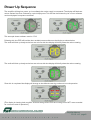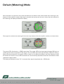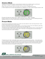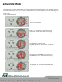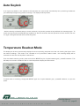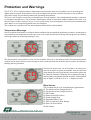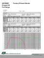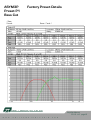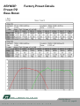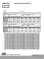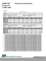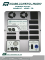
1
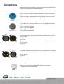
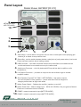
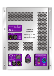
USER MANUAL
ASYM3P - VSB215P
W
World HQ: Unit 7 Lockwood Ind. Park, Mill Mead Road, London, N17 9QP. U.K.
t l
f
i
or ld
tel: +44 (0) 208
skype: NoiseControlHQ
email: [email protected]
808 1923
W
A UO DL I AO U. CD O I MO . C O M
W WW W W. N. ON I OS IE SC EO N
C TO R NO TL R
Important Safety Information
Do not remove Covers.
No user serviceable parts inside, refer
servicing to qualified service personnel.
This equipment must be earthed.
CAUTION
RISK OF ELECTRIC SHOCK
DO NOT OPEN
DO NOT EXPOSE TO RAIN OR MOISTURE
ATTENTION
RISQUE DE CHOC ELECTRIQUE
NE PAS ENLEVER
NE PAS EXPOSER A LA PLUIE NI A L’HUMITE
Objects containing liquids, such as vases, must not be placed on this equipment.
It should not be necessary to remove any protective earth or signal cable shield connections.
The mains plug is the disconnection device, and must remain accessible when the equipment is in use.
The mains switch does not provide complete disconnection of the equipment from the mains.
Do not defeat the purpose of the polarized or grounding-type plug. A polarized plug has two blades with
one wider than the other. A grounding type plug has two blades and a third grounding prong. The wider
blade and the third prong are provided for your safety. When the provided plug does not fit into your
outlet,
consult an electrician for replacement of the obsolete outlet.
Only use a Neutrik Powercon mains connector to connect to the apparatus. The part number for this is
connector is NAC-3MPA. Only use this equipment with an appropriate mains cord.
The mains cord should be a sheathed type and comply with IEC 60227 for PVC cords, or IEC 60245 for
rubber cords. The cable must be a three-core cord with 2.5mm2 conductors.
In the USA the cord should comply with the requirements contained in the Standard for CordSets and
Power Supply Cords, UL 817, be marked VW-1, and have an ampacity rating not less than the marked
rating of the apparatus.
Caution - Replace the main fuse ONLY with the exact same type as specified - that is:
For 230V operation:
Manufacturer: Schurter
Description: FF16A Super quick acting 6.3mm x 32mm Ceramic Fuse
Manufacturer's Part Number: 7022.0470
For 115V operation:
Manufacturer: Schurter
Description: FF16A Super quick acting 6.3mm x 32mm Ceramic Fuse
Manufacturer's Part Number: 7022.0470
Please do NOT operate the amplifier with no load connected, or with the covers removed. The covers are
integral to the control of air through the unit and without them, the amplifier may overheat and shut
down. Whilst this will not damage it, it may be seen as faulty when it is in fact working correctly and just
protecting itself!
Dangerous, potentially lethal, voltages exist on exposed parts and care must be taken not to touch any
metallic parts when the covers are removed. Remember that the large reservoir capacitors are capable
of storing large amounts of energy for long periods after the amplifier has been turned off!
W
t l
W
W
f
or ld
W
.
N
O
I S
E
Amplifier Manual
FF 2.5 - 4.5 page 2
i
C
O
N
T
R
O
L
A
U
D
I O
.
C
O
M
Introduction
Thank you for purchasing the ASYM3P - VSB215P Series Powered Speaker. Please take a moment to
read through this manual to ensure you get the very best out of the product.
The FF 2.5 - 4.5 Series Digital Power Amplifiers used have been designed to offer cutting edge
performance in terms of sound quality, efficiency and innovative design features.
They feature two independent amplifier sections providing unrivalled levels of power and performance in a
small lightweight package.
The amplifiers are switching designs, as is the power supply for them, leading to much higher efficiency
and so less wasted power.
Both amplifiers and their power supply are monitored by a microprocessor, which constantly checks their
performance and monitors for fault conditions, shutting down in the event of any dangerous or potential
harmful situations.
A digital signal-processing module is also built into the amplifier. This high quality design implements all
the necessary filtering and dynamics processing to realise various crossover functions, such as band
pass filters, polarity switching, driver time alignment and limiting. Ten preset memories are provided to
allow instant recall of different configurations.
A USB port is provided for loading different preset configurations and into the module's memory and for
updating the firmware.
A simple control interface allows quick and easy adjustment of the system volume, selection and recall of
presets, and metering of the two amplifiers signal levels. It also provides feedback in the event of any
potential fault conditions, including operating temperature.
This interface features an autolock feature to prevent unauthorised adjustment to settings. This locks all
keys 60 seconds after power-up and automatically relocks the keys 60 seconds after any adjustment is
made
Amplifier Manual
FF 2.5 - 4.5 page 3
W
W
W
.
N
O
I S
E
C
O
N
T
R
O
L
A
U
D
I O
.
C
O
M
Connections
Before plugging the amplifier in, please familiarise yourself with the
front panel connections as explained below.
The mains power inlet is a standard Neutrik Powercon connector.
This is lockable, and the connections for live, neutral and earth are
clearly marked in the appropriate plug. Please do not use cable
rated at less than 10A continuous ampacity.
The outputs from the two amplifiers are via a single Neutrik Speakon
and are connected as follows:
Pin 1+: Low Amp Positive
Pin 1 - : Low Amp Negative
Pin 2+: High Amp Positive
Pin 2-: High Amp Negative
Audio Signal
IN
Input to the amplifier is via a standard XLR connector and is wired as:
Pin 1: Ground
Pin 2: Hot
Pin 3: Cold
The link output is via a standard XLR connector and is wired as:
Pin 1: Ground
Pin 2: Hot
Pin 3: Cold
OUT
RS 485
IN
The RS485 Network connections are via a standard XLR connector
and is wired as:
Pin 1: Ground
Pin 2: Hot
Pin 3: Cold
OUT
We do not recommend making USB cables from scratch
– please use a ready made cable.
Amplifier Manual
FF 2.5 - 4.5 page 4
t l
W
W
W
.
N
O
I S
E
C
O
N
T
R
O
L
A
U
D
I O
.
C
O
M
Panel Layout
Model Shown ASYM3P (FF 2.5)
9
NETWORK ONLY
NOT FOR AUDIO !
10
1
2
6
3
4
5
AUDIO IN
7
8
1. Adjust Keys - used to either change the volume of the module (with accompanying gain
readout) or to select a new preset to load.
2. Select Key - used to switch between default mode (volume) and preset select/load mode
Please see later sections about loading presets.
3. USB Connector – this data connection allows new preset files to be loaded into the
module and stored in non-volatile memory for instant recall.
4. Audio Input Connector – this fully balanced XLR input drives both amplifiers and is
hardwired to…
5. Link Output Connector – provides an output to link the audio through to another
amplifier module.
6. Slave Speaker Output (FF 4.5 0NLY - NOT SHOWN) – high power outputs
from the amplifiers to the speakers – please note there can be dangerous
voltages present here at high audio levels.
7. Mains Power Switch – Swithes the amplifier/speaker on and off !
8. Mains Power Inlet – Mains voltage input – 230V AC, 50-60Hz. Only use genuine Neutrik
Powercon connectors that are lockable.
9. RS485 - network connection input (NOT FOR AUDIO)
10. RS485 - network connection output (NOT FOR AUDIO)
Amplifier Manual
FF 2.5 - 4.5 page 5
W
or ld
W
W
W
.
N
O
I S
E
C
O
N
T
R
O
L
A
U
D
I O
.
C
O
M
Power Up Sequence
The amplifier will begin to power up immediately the mains supply is connected. The display will flash two
amber dashes five times, followed by a quick display test. This will then be followed by the current software
version displayed in sequence as below:
This example shows software version 1.04.
Following this, the DSP will load the last recalled preset, evident on the display as shown below.
The audio will fade up slowly to the last set volume, with the display will briefly show the volume setting.
The audio will fade up slowly to the last set volume, with the display will briefly show the volume setting.
Once this is completed the display will change to the default metering mode and normal operation.
(This display is showing both amplifier channels being driven hard into limiting and is NOT recommended
as a normal mode of operation!)
Amplifier Manual
FF 2.5 - 4.5 page 6
W
W
W
.
N
O
I S
E
C
O
N
T
R
O
L
A
U
D
I O
.
C
O
M
Default (Metering) Mode
After the power up sequence, the module will default to its default mode, which shows level metering on the
display for both amplifier modules. Note that if the audio level present at the input is lower than the threshold of
the metering, the display will default to display.
Once signal is received, the metering will show the output levels of the two amplifier modules, as shown below.
The green LEDs illuminate at –40dB output level. The amber LEDs illuminate approximately 6dB prior to
reaching the limiter threshold for that output. The red LEDs illuminate approximately 1dB from limiting.
Note that the threshold for the green LEDs is fixed, but as different presets may have different limiter
thresholds, the amber and red LED thresholds are automatically adjusted to follow the thresholds of their
respective output limiters.
The display will default to show “On” 4 seconds after signal drops below the –40dB point.
Amplifier Manual
FF 2.5 - 4.5 page 7
W
W
W
.
N
O
I S
E
C
O
N
T
R
O
L
A
U
D
I O
.
C
O
M
Volume Mode
The gain (or volume) of the amplifiers may be adjusted in tandem from the default mode my pressing the
Adjust keys as required. The display will instantly switch to show the attenuation in dB.
Please note that on Firware versions 4 and later the volume adjust is a 40dB attenuator only.
ie. Volume adjustment can only be made downward, any reading from 0 - 40 is a measure of gain reduction in dB.
On previous firmware the maximum gain is +9dB, and the minimum is –9dB, in 1dB steps.
Holding an Adjust key in will accelerate the volume change after approximately 3 seconds. Releasing the key will
display the volume for 2 further seconds, before reverting back to metering mode.
Preset Mode
A single press of the Select key will switch the module into preset selection mode, and initially show the number
of the currently loaded preset in amber as below.
If all that is required is to check the preset number or volume setting, another press on the Select key will briefly
show the current volume setting and then default back to the metering mode.
To change and recall a different preset, when the current preset number is visible as above, use the Adjust keys
to scroll up and down to the number required. The “P” will remain on the display with the number flashing to
show that this preset has not been loaded yet.
To escape from this mode, use the Adjust keys to get back to the original preset number – this is shown by the
number not flashing - then press Select again to exit. If a new preset is to be loaded. Select it as described above,
then press Select again. Both digits will flash 5 times and then the preset number will become static. The audio
will fade down and back up with the new preset loaded. When complete, the volume will briefly be displayed,
and the module will return to the default metering mode.
W or ld H Q : Unit 3 S tephen Hous e, 1 (B ) Dar nley R oad, London E9 6 QH, UK
t el:l +4 4 (0 ) or
2 0ld8 5 1 0 9 0 1 0 fa
f x: +4 4 (0 ) 2 0 8 5 3 3 1 4 3 3 ema il:
i : info@ nois econtr olaudio. com
Amplifier Manual
FF 2.5 - 4.5 page 8
Network ID Mode
A second press of the Select key will switch the module into Network ID mode. The latest version of software - that is
version 4.00 and above for the FF 2.5 and version 5.00 and above for the FF 4.5 Support full real-time remote control
of all parameters for preset design via the USB connection, and many new features for network monitoring and
remote control.
The display will flash between
and one of the following:
Flashing "no" indicates that the external comms
are disabled. Press Adjust UP to move through
the av ailable ID numbers as below…
I D 01 is the default setting and is used for access
via the USB port connection only.
Uploading of preset files, new firmware, or live preset
design must be via the USB connection.
.
ID numbers 02 to 64 are network IDs and are
accessed through the RS485 port connection only.
The RS485 port is to be used for network monitoring
purposes only, with PC software available soon.
The global ID "AL" is used for factory diagnostic
purposes and should not be used.
Amplifier Manual
FF 2.5 - 4.5 page 9
W
W
W
.
N
O
I S
E
C
O
N
T
R
O
L
A
U
D
I O
.
C
O
M
Auto Keylock
If no keys are pressed on the module for 60 seconds, the controls will automatically lock, preventing inadvertent
(or unwanted!) changes being made to settings. The display will briefly shown.
…before reverting to whatever was on screen previously. Any further presses of keys will flash this message again. To
unlock the keys, press both ADJUST keys together for about 2 seconds. Normal operation will then resume, with the
unit again locking 60 seconds after the last key press.
Temperature Readout Mode
The display can be set to permanently display the current operating temperature of the unit, showing the higher of the
two sensor readings. This mode is not intended to be a permanent readout mode - the metering display will be
restored the next time the amplifier is switched on.
From the default metering mode, press and hold the SELECT key for 2 cycles between gain/ presetID readouts. This
will swap from meters in default mode to a red temperature display as shown below.
To switch back to metering, simply hold SELECT again for 2 cycles between gain/ presetID readouts, or cycle the
power.
Amplifier Manual
FF 2.5 - 4.5 page10
W
W
W
.
N
O
I S
E
C
O
N
T
R
O
L
A
U
D
I O
.
C
O
M
Protection and Warnings
The FF 2.5 - 4.5 is equipped with an advanced microprocessor than not only takes care of controlling the
digital signal processor responsible for the audio management, but also monitors the status of the amplifiers
and power supply, and constantly checks the operating temperature.
The fans in the amplifier are directly controlled by the microprocessor, each independently variable in response
to changes in temperature. The processor also keeps a check of the actual rotational speed of the fans, so is
aware if either of them stops turning, or is turning too slowly. This can happen if the vents become blocked with
dust/debris or a foreign body gets stuck in the amplifier.
The module has a series of errors that it displays which will be outlined below.
Temperature Warnings
As the amplifier temperature increases above ambient, the fan speed will gradually increase in an attempt to
compensate. If the temperature continues to rise, at a certain threshold the display will change from the default
metering readout to a flashing warning in red.
The temperature may continue to rise, and the amplifier will carry on working normally. Once the temperature
reaches a level that is likely to cause damage to internal components, the amplifier will shut down, and display a
flashing warning as below.
The fans will continue to run at full power in an attempt to
cool the amplifier as quickly as possible. If the temperature
drops below the warning threshold, the amplifier power will
be restored. However, whilst the error display will clear, a
warning will be displayed until the amplifier is switched off
and on again, in the form of an “E –“ display as below.
Other Errors
The complete list of error code displays is given below:
E1 Temperature Over Range Sensor 1
E2 Temperature Over Range Sensor 2
E3 DC Protect
E4 General Amplifier Failure
E5 Power Supply Fault
E6 Over-Modulation Fault
E7 PSU Temperature Over Range
E8 Over Current Protect
E9 Fan Failure
Amplifier Manual
FF 2.5 - 4.5 page11
W
W
W
.
N
O
I S
E
C
O
N
T
R
O
L
A
U
D
I O
.
C
O
M
Warnings in detail
Error warnings and recovery in detail…
E1 ---- Temperature Over Range Sensor 1
E2 ---- Temperature Over Range Sensor 2
See section on previous page detailing how over temperature conditions are handled.
E4 ----
General Amplifier Protect
This condition will shut the amplifier and power supply down and require a restart to clear the fault condition (if
possible). If the warning still appears, contact Noise Control Audio.
E5 and E8 ---- Power Supply Protect and Mains Voltage Low
If the mains voltage is close to the threshold where correct operation cannot be maintained, this will be evident on
loud peaks as the amplifier muting and the audio fading back in, accompanied by E8. This cycle will continue until
either the level is reduced, or the mains voltage is increased.
If the voltage continues to drop, over-modulation protection additionally is triggered, showing E6 and E8 in sequence.
Any further drop in mains voltage will cause the amplifier to protect its power supply, with the display showing E5 and
E6 in sequence.
In any of these cases, restoration of a good mains supply will result in the amplifier clearing the errors and functioning
again normally without the need to restart.
If, however, the amplifier is turned on and the measured mains voltage is too low to allow any operation, the display will
show E5 and E8 in sequence for a few seconds, before reverting to E5. If the mains voltage is restored to a normal
operating level, this will clear to E- (showing the fault has been rectified), and a restart will allow the amplifier to
function normally.
If the amplifier displays an E5 immediately on start-up, there is a power supply fault - contact Noise Control Audio.
E6 ---- Over-Modulation Protect
If the amplifier is being driven too hard into too low a load, it will try to keep operating for as long as possible by
adapting the limiter thresholds accordingly. If this does not succeed in reducing the modulation level enough, the
amplifier will briefly switch off and then back on, accompanied by the audio fading up and E6 displayed.
E9 ---- Fan Failure
If either of the fans (or blower) is turning too slowly (or not at all) the amplifier will mute and display
subsequently begins to turn again, the amplifer's power will be restored and audio will fade back up
E9.
If the fan
Note that most error conditions, with the exceptions of the initial temperature warning and the fan failure, will
result in the amplifier shutting down.
If the fault has not cleared when the amplifier is next powered up it will not operate, and continue to show
any error codes in sequence, if more than one exists. No adjustments are possible in this mode – please
contact us to resolve this.
Amplifier Manual
FF 2.5 - 4.5 page12
W
W
W
.
N
O
I S
E
C
O
N
T
R
O
L
A
U
D
I O
.
C
O
M
USB Port
TThe USB port is designed to allow the uploading of new presets into the module. The amplifier software
now supports high speed real time control of all aspects of the integrated DSP, as well as extensive
monitoring and remote control capabilities. Presets may be stored and recalled individually, and
"prepacked" preset files may also be accepted to configure a module in one simple operation.
The operating firmware may also be remotely updated..
Amplifier Manual
FF 2.5 - 4.5 page13
W
W
W
.
N
O
I S
E
C
O
N
T
R
O
L
A
U
D
I O
.
C
O
M
ASYM3P
Preset P0
Full Range
Factory Preset Details
Amplifier Manual
FF 2.5 - 4.5 page14
W
W
W
.
N
O
I S
E
C
O
N
T
R
O
L
A
U
D
I O
.
C
O
M
ASYM3P
Preset P1
Bass Cut
Factory Preset Details
Amplifier Manual
FF 2.5 - 4.5 page15
W
W
W
.
N
O
I S
E
C
O
N
T
R
O
L
A
U
D
I O
.
C
O
M
ASYM3P
Preset P2
Bass Boost
Factory Preset Details
Amplifier Manual
FF 2.5 - 4.5 page16
W
W
W
W
or ld
. N
O
I S
E
C
O
N
T
R
O
L
A
U
D
I O
.
C
O
M
VSB215P
Preset P0
80Hz HPF
Factory Preset Details
Amplifier Manual
FF 2.5 - 4.5 page17
W
W
W
.
N
O
I S
E
C
O
N
T
R
O
L
A
U
D
I O
.
C
O
M
VSB215P
Preset P1
120Hz HPF
Factory Preset Details
Amplifier Manual
FF 2.5 - 4.5 page18
W
W
W
.
N
O
I S
E
C
O
N
T
R
O
L
A
U
D
I O
.
C
O
M