1
PELCO Camera and SCADA Integration
Guide
PELCO Viewer v3.0
May 2011
Legal Notice
DISCLAIMER
Schneider Electric (Australia) Pty. Ltd. makes no representations or warranties with respect to this manual and, to
the maximum extent permitted by law, expressly limits its liability for breach of any warranty that may be
implied to the replacement of this manual with another. Further, Schneider Electric (Australia) Pty. Ltd. reserves
the right to revise this publication at any time without incurring an obligation to notify any person of the revision.
COPYRIGHT
© Copyright 2011 Schneider Electric (Australia) Pty. Ltd. All rights reserved.
TRADEMARKS
Schneider Electric (Australia) Pty. Ltd. has made every effort to supply trademark information about company
names, products and services mentioned in this manual.
Citect, CitectHMI, CitectFacilities, PELCO, Vijeo Citect, Vijeo Citectlite and CitectSCADA are registered trademarks
of Schneider Electric (Australia) Pty. Ltd.
IBM, IBM PC and IBM PC AT are registered trademarks of International Business Machines Corporation.
MS-DOS, Windows, Windows NT, Windows Vista, Windows 7, Microsoft, and Excel are either registered trademarks or trademarks of Microsoft Corporation in the United States and/or other countries.
All other brands and products referenced in this document are acknowledged to be the trademarks or registered
trademarks of their respective holders.
GENERAL NOTICE
Some product names used in this manual are used for identification purposes only and may be trademarks of
their respective companies.
PLEASE NOTE
Electrical equipment should be installed, operated, serviced, and maintained only by qualified personnel. No
responsibility is assumed by Schneider Electric (Australia) Pty. Ltd. for any consequences arising out of the use of
this material. © 2011 Schneider Electric (Australia) Pty. Ltd.. All Rights Reserved.
Validity Note
The present documentation is intended for qualified technical personnel responsible for the implementation, operation and maintenance of the products described. It contains information necessary for the proper use of the products. However, those who wish to make a more "advanced" use of our products may find it necessary to consult
our nearest distributor in order to obtain additional information.
The contents of this documentation are not contractual and in no way constitute an extension to, or restriction
of, the contractual warranty clauses.
Contact Schneider Electric today at www.schneider-electric.com/vijeocitect
Contents
Legal Notice
2
Contents
3
Introduction
7
Safety Information
Chapter 1: PELCO Viewer Usage
Supported PELCO cameras
Chapter 2: Installing the PELCO ActiveX Control
Installation requirements
System software
System hardware
Installing the PELCO Viewer ActiveX Control
Verifying the camera video streaming
Finding the camera's IP address, port and number
Checking camera availability
Chapter 3: Connecting to a PELCO Camera from a Project
Configuring during design time
Adding the PELCO Viewer ActiveX Control
Configuring PELCO Viewer properties
Using tag association
Controlling the camera
Compiling and Running the Project
Using Cicode
Saving settings between page transitions
9
13
13
15
15
15
16
18
18
20
20
23
23
23
24
25
26
27
28
29
3
Contents
Chapter 4: PELCO Example Project
PELCO Camera Management page
Camera Alarm Link
Genies
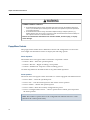
Chapter 5: Further Viewer Features
Pan, Tilt and Zoom toolbar
Popup Menu Controls
PELCO Viewer mouse controls
RTSP and Sarix cameras
Reference
Chapter 6: PELCO Viewer ActiveX Control Interface Properties
Properties
AutoConnect
Bandwidth
CameraNumber
CameraIpAddress
CameraPortNumber
HomePresetId
ReverseTilt
RtspMode
RtspUrl
UnicastStream
UnicastStreamIP
UnicastStreamPort
VelocityHorizontal
VelocityVertical
Reading and writing to properties
Chapter 7: PELCO Viewer ActiveX Control Interface Methods
31
31
32
33
33
34
36
36
37
39
40
40
40
41
41
41
42
42
42
42
43
43
44
44
44
44
47
Connection Methods
Customize User Interface methods
PTZ Methods
Preset Methods
Pattern Methods
47
48
49
50
52
Chapter 8: Troubleshooting
55
Devices and tools
Implementation checklist
Debugging procedure
Enabling event logs
Troubleshooting guide
4
31
55
56
56
57
57
Contents
Glossary
63
Index
65
5
Contents
6
Part: 1
Introduction
This section introduces the PELCO Viewer ActiveX® Control and
describes how to install the control on a SCADA computer. In this
document, SCADA will refer to either Vijeo Citect, CitectSCADA or
CitectFacilities software.
Safety Information
PELCO Viewer Usage
Installing the PELCO ActiveX Control
Connecting to a PELCO Camera from a Project
PELCO Example Project
Further Viewer Features
7
8
Safety Information
Hazard categories and special symbols
The following symbols and special messages may appear in this manual or on the product to warn of potential hazards or to call attention to information that clarifies or simplifies a procedure.
A lightning bolt or ANSI man symbol in a "Danger" or "Warning" safety label on the
product indicates an electrical hazard which, as indicated below, can or will result in
personal injury if the instructions are not followed.
The exclamation point symbol in a safety message in a manual indicates potential personal injury hazards. Obey all safety messages introduced by this symbol to avoid possible injury or death.
Symbol
Name
Lightning Bolt
ANSI man
Exclamation Point
DANGER indicates an imminently hazardous situation which, if not avoided, will result in
death or serious injury.
WARNING indicates a potentially hazardous situation which, if not avoided, can result in
death or serious injury.
9
Safety Information
CAUTION indicates a potentially hazardous situation which, if not avoided, can result in
minor or moderate injury.
CAUTION
CAUTION used without the safety alert symbol indicates a potentially hazardous situation
which, if not avoided, can result in property damage.
Please Note
Electrical equipment should be installed, operated, serviced, and maintained only by
qualified personnel. No responsibility is assumed by Schneider Electric (Australia) Pty.
Ltd. for any consequences arising out of the use of this material.
Before You Begin
SCADA stands for Supervisory Control and Data Acquisition (SCADA) solution. It facilitates the creation of software to manage and monitor industrial systems and processes.
Due to SCADA’s central role in controlling systems and processes, you must appropriately design, commission, and test your SCADA project before implementing it in an
operational setting. Observe the following:
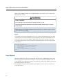
UNINTENDED EQUIPMENT OPERATION
Do not use SCADA software as a replacement for PLC-based control programs. SCADA software is not designed for direct, high-speed system control.
Failure to follow these instructions can result in death, serious injury, or equipment damage.
10
Safety Information
LOSS OF CONTROL
l
l
l
l
The designer of any control scheme must consider the potential failure modes of control
paths and, for certain critical control functions, provide a means to achieve a safe state
during and after a path failure. Examples of critical control functions are emergency
stop and overtravel stop.
Separate or redundant control paths must be provided for critical control functions.
System control paths may include communication links. Consideration must be given to
the implications of unanticipated transmission delays or failures of the link.*
Each implementation of a control system created using SCADA must be individually and
thoroughly tested for proper operation before being placed into service.
Failure to follow these instructions can result in death, serious injury, or equipment damage.
UNINTENDED EQUIPMENT OPERATION
Integration of PELCO camera streaming with SCADA is provided as an aid and is not intended
to replace a complete security monitoring system.
Failure to follow these instructions can result in death, serious injury, or equipment damage.
* For additional information, refer to NEMA ICS 1.1 (latest edition), "Safety Guidelines
for the Application, Installation, and Maintenance of Solid State Control".
11
Safety Information
12
Chapter 1: PELCO Viewer Usage
The PELCO Viewer ActiveX Control is designed for the PELCO Camera Video Streaming
interface in CitectSCADA, CitectFacilities and Vijeo Citect.
The PELCO Viewer ActiveX Control provides the ability to stream video through a
SCADA runtime page and control the camera.
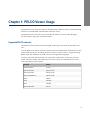
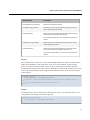
Supported PELCO cameras
The PELCO camera interface was developed for the Spectra IV Series IP and Sarix cameras.
Current PELCO IP cameras (cameras that have been launched before 31/01/2011) are supported with this release, including the Sarix range of cameras. Sarix is supported using
RTSP, while the remainder of the IP cameras are supported using RTP.
Cameras launched after 31/01/2011 are expected to work but the control has not been
tested with later models. The table below lists the cameras for which the Pelco Viewer
ActiveX Control has been tested.
Camera
Model
Fixed IP Camera
IP 3701
Spectra IV Dome
Spectra IV-IP
Spectra IV Dome
Spectra IV-IP
Spectra IV PND 35X
Spectra IV-IP
Sarix
IXE20C
Sarix
IX10DN
Sarix
IXS0DN
Spectra HD Sarix
D5118
13
Chapter 1: PELCO Viewer Usage
14
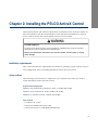
Chapter 2: Installing the PELCO ActiveX Control
Minimum hardware and software requirements for PELCO Viewer ActiveX Controls for
Microsoft Windows XP, Microsoft Windows Vista and Microsoft Windows 7 must be
met in order to install and run the PELCO Viewer ActiveX Control.
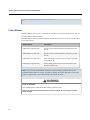
SYSTEM STABILITY
The Pelco Viewer ActiveX Control must be installed on a SCADA display client to avoid additional CPU and memory overhead on the SCADA server.
Failure to follow these instructions can result in death, serious injury, or equipment damage.
Installation requirements
This section describes the requirements for hardware, operating system software and system configuration prior to installing the PELCO Viewer ActiveX Control.
System software
The following system software is required on any computer onto which you want to
install the PELCO Viewer ActiveX Control.
Supported operating systems
Windows XP Professional with Service Pack 3 - (32 Bit and 64 Bit)
Windows Vista with Service Pack 2 (32 Bit and 64 Bit)
Windows 7 with Service Pack 1 (32 Bit and 64 Bit)
Other software
l
SCADA 7.00 or later
l
Microsoft .NET Framework 3.5 SP1
l
Microsoft Visual C++ 2008 Redistributable SP1
15
Chapter 2: Installing the PELCO ActiveX Control
l
A Local Area Network (LAN) if you want to have the client access a remote server.
l
Microsoft DirectX 9.0 on Windows XP and 10 on Windows Vista or later
l
Sentinel key protection
If you experience problems installing Microsoft .NET framework, download the full .NET
3.5 SP1 installation from the Microsoft site and manually install it, then run the PELCO
installation. Alternatively install SCADA 7.20 (which includes .NET 3.5 SP1) first.
If you are prompted by the PELCO installer to install the .NET Framework 3.5 Sp1 you
will be redirected to the Microsoft download site to install it. If you are directed to
another version of the .NET Framework, please choose the .NET Framework 3.5 Service
Pack 1 from the web page to ensure successful installation and function of the PELCO
Viewer. Alternatively install SCADA 7.20 (which includes .NET 3.5 SP1) before installing
PELCO.
Software installed with the PELCO Viewer ActiveX Control
l
ATL Security
System hardware
The PELCO Viewer is a resource intensive component and as such, hardware that meets
the recommended requirements should be selected for a SCADA client.
The ActiveX control requires DirectX 3D Acceleration enabled hardware, where video
stream rendering is handled by an external processor and RAM configuration on the
graphics card.
The following hardware is recommended for a computer that is used as a client running
PELCO camera video stream. The display adapters listed below have been tested. Some
graphics cards may provide poor quality video and, in some circumstances, loss of
colour and pixelation. See Video Streaming Performance for more information on the
impact of concurrent video streams on graphics card performance.
The following tables indicate the computer hardware requirements for the SCADA
PELCO ActiveX installation.
16
Chapter 2: Installing the PELCO ActiveX Control
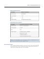
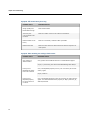
Minimum hardware requirements
Description
Minimum specification
Processor Type
Intel Pentium 4
Processor Speed
2 GHz
RAM
1 GB
Graphics Adapter
256 MB dedicated video memory
Recommended hardware requirements
Description
Recommended specification or higher
Processor Type
Intel Core™ 2 Duo CPU E7500
Processor Speed
2.93 GHz
RAM
4 GB
Graphics Adapter
ATI Radeon HD 3450 - Dell Optiplex
NVDIA GeForce Go 7400
ATI Radeon HD 3450 Pro
1 GB or more dedicated video memory
Note: It is recommended that you run the PELCO interface on dedicated clients and
not on any of the other I/O, Alarm or Report Servers.
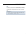
Video streaming performance
Video streaming with DirectX requires a lot of CPU, memory and especially dedicated
on-board video memory. The more dedicated on-board video memory, the more concurrent video streaming connections can be supported.
17
Chapter 2: Installing the PELCO ActiveX Control
POOR PERFORMANCE
l
l
The PELCO Viewer requires a graphics adapter with sufficient video memory as indicated in the table below.
Ensure that no more than four concurrent video sessions are streamed on a single
SCADA graphics page.
Failure to follow these instructions can result in death, serious injury, or equipment damage.
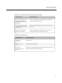
Depending on your computer’s dedicated video memory you should experience reasonable video stream quality, performance, and responsiveness providing that number
of concurrent video streaming controls on the same page does not exceed the number in
the table below.
Graphic Card Dedicated Video
Memory
Max. Number of Concurrent Video
Streaming
256 MB
1-2
512 MB
2-4
Installing the PELCO Viewer ActiveX Control
To install the PELCO Viewer ActiveX Control, run "setup.exe" from the installation
media. Follow the onscreen prompts to complete installation of the control.
Documentation
After a successful installation, the documentation is available from the Windows Start
menu (Start > Programs > Schneider Electric > PELCO > PELCO User Guide).
Verifying the camera video streaming
The video rendering can be verified by launching the PELCO Diagnostic Player. PELCO
Diagnostic Player can be launched either from the installed directory or the Windows
Start menu (Start > Programs > Schneider Electric > PELCO > PELCO Diagnostic Player).
A console window and the PELCO Diagnostic Player will be displayed.
At the bottom of the PELCO Diagnostic Player window, click the Configuration button
to launch the Network Stream Settings dialog box.
18
Chapter 2: Installing the PELCO ActiveX Control
DELAYED OR INCORRECT VIDEO
Ensure that cameras are configured to overlay the time-stamp & camera information on the
video stream to assist operators in correctly identifying the camera and the time at which the
image was relayed.
Failure to follow these instructions can result in death, serious injury, or equipment damage.
If using RTP mode to connect to the camera, please ensure you enter valid values for:
l
Camera IP address
l
Camera Port (default is 49152 - check camera manual)
l
ServiceID set to 1 (default camera number)
Optionally enter valid values for:
l
Local IP address
l
Local Port (default is 9102)
l
Select the unicast check box
If using RTSP mode to connect to a Sarix camera, the connection can be established
using the following RTSP URL:
RTSP://<IP Address>/stream1
Note: "stream1" or "stream2" is required as a string to connect to the camera.
Press the Connect button. The PELCO Diagnostic Player window should display live
video streamed from your camera.
If the viewer is not showing live video image from your camera, that is the player shows
the default PELCO screen, then the camera is not connected. Please make sure that all
required software is installed on your computer and that the correct IP addresses and
ports are used. If the lack of connection persists, see Troubleshooting which contains
information on testing the camera using the PELCO software.
Note: Check that the ports are not blocked by the network administrator and that the
IP addresses are accessible.
19
Chapter 2: Installing the PELCO ActiveX Control
Finding the camera's IP address, port and number
Finding the IP address
You can use the PELCO Device Utility to determine the IP address of your camera. The
PELCO Device Utility can be found on the resource CD which is shipped with the camera. For information about how to install the PELCO Device Utility, please refer to the
PELCO documentation.
1. Choose Start > Programs > PELCO > Device Utility > PELCODeviceUtility
2. Your camera’s IP address will be shown after the PELCO Device Utility has started
3. If the camera’s IP address is still not shown then click the “Search Now” button and
your camera should be detected by the utility.
4. If your camera’s IP address is still not shown, make sure it is connected to your network and that the camera is not blocked by your network. In some cases, the
addresses are blocked by network administrators or local network rules.
Finding the port number
PELCO IP cameras usually have default ports of either 49152 or 49157. A different port
number can be assigned. For further information, please refer to your PELCO camera's
manual.
Alternatively, reset the values to the factory defaults with the reset button on the camera.
Finding the camera number
In the majority of cases, the default number is 1. If the camera is used in conjunction
with a PELCO DVR, then the camera number is assigned on the DVR.
Checking camera availability
There are two ways to check the availability of a camera from your computer, using the
PELCO Device Utility or using Internet Explorer.
Using the PELCO Device Utility
You can use the PELCO Device Utility to determine availability of your camera. The
PELCO Device Utility can be found on the resource CD shipped with the camera. For
information about how to install the PELCO Device Utility, please refer to the PELCO
camera's documentation.
20
Chapter 2: Installing the PELCO ActiveX Control
1. Choose Start > Programs > PELCO > Device Utility > PELCODeviceUtility
2. Click the Connect button for your camera.
Using Internet Explorer
1. Open Microsoft Windows Internet Explorer and enter the camera’s IP address in the
URL field. For example, http://10.176.234.163
2. The login window will be displayed.
3. Log in with your user name and password. The defaults are “admin” and “admin,”
if you have not changed them.
4. After the first successful login, you will be prompted to install an ActiveX control on
your computer. Accept it and install the ActiveX control on your computer.
5. Once the installation is complete, your camera will be connected and video will
stream in your browser.
If there are any difficulties, please refer to Troubleshooting, your PELCO manual or contact PELCO support to address this before proceeding further with the project.
21
Chapter 2: Installing the PELCO ActiveX Control
22
Chapter 3: Connecting to a PELCO Camera from a
Project
There are three ways to connect to a PELCO camera from within a SCADA project:
l
Configuring during design time
l
Using tag association
l
Using Cicode
Configuring during design time
The quickest method of using a PELCO camera in your project is to place the PELCO
Viewer ActiveX control on a page and then configure it directly:
1. Add a PELCO Viewer ActiveX control to your page (see Adding PELCO Viewer ActiveX Control).
2. Configure the camera’s configuration properties directly in the PELCO Viewer Properties window (see Configuring PELCO Viewer Properties).
3. Compile and run the project.
4. Once the project is running, update your Page List from the Pages menu and then
navigate to the new camera page.
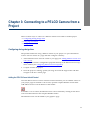
Adding the PELCO Viewer ActiveX Control
Once the PELCO Viewer ActiveX Control has been installed, you can add the Viewer to
your project pages. In SCADA v7.20 or later, open the Graphics Builder and click the
Add PELCO Viewer ActiveX button on the toolbar:
In SCADA v7.10 or earlier, the PELCO Viewer can be inserted by clicking on the Insert
ActiveX Control button in the Graphics Builder toolbar.
The PELCO Viewer will be added to your graphics page.
23
Chapter 3: Connecting to a PELCO Camera from a Project
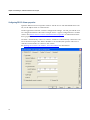
Configuring PELCO Viewer properties
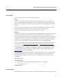
Open the PELCO Viewer Properties window. On the Access tab and Identification subtab, set the Object Name to “PELCOCam”.
On the Appearance tab and “Camera Configuration Settings” sub tab, provide the camera configuration details. The below example shows a typical configuration for an RTP
camera. See PELCO Viewer ActiveX Control Interface Properties for information about
these properties.
Click the “Automatically connect to camera” checkbox to automatically connect the camera to the Viewer upon start. If this checkbox is not checked, the operator will have to
click the Connect button to connect to the camera.
See Finding the Camera's IP Address, Port and Number for information.
24
Chapter 3: Connecting to a PELCO Camera from a Project
INCORRECT VIDEO DISPLAYED
Ensure that continuous port numbers are not used for multiple cameras on the same page
when using unicast stream.
Failure to follow these instructions can result in death, serious injury, or equipment damage.
When working with two or more cameras on a single page, unicast stream port values
should not be continuous because the next immediate port numbers are reserved for PTZ
operations. For example, if you have configured the unicast stream port value as 9001
for one camera and 9002 is used for the next camera then both cameras will display the
same image.
Once the configuration is updated, click the Apply button.
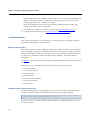
Using tag association
To create a PELCO Viewer control using tag association:
1. Create Tags for camera properties.
To be able to connect to a PELCO camera from the PELCO Viewer ActiveX Control at
runtime, you will need to pass the camera connection information to an object in the
PELCO Viewer ActiveX Control. These camera properties are stored in tags defined
within SCADA. For details about how to create tags, please refer to the SCADA online
help.
For example, for each RTP camera the following basic camera properties must be
defined:
l
Camera IP address – String type
l
Camera port number – Long type
l
Camera number – Long type
l
Unicast stream – Digital type
l
Unicast stream IP address – String type
l
Unicast port number – Long type
l Auto Connect – Digital type
For a full list of camera properties see PELCO Viewer ActiveX Control Interface Properties.
2. Add a PELCO Viewer ActiveX control to your page (see Adding the PELCO ActiveX
Control).
3. Map tags to properties.
25
Chapter 3: Connecting to a PELCO Camera from a Project
Open the PELCO Viewer Properties window. On the Access tab and the Identification
subtab, set the Object Name to "PELCOCam". Make sure the “Persist ActiveX data
between page transitions” checkbox is checked.
Then on the Appearance tab and Tag Association sub-tab, map the variable tags
created above to the camera's properties.
4. Create buttons and objects to control the camera (see Controlling the camera).
5. Compile and run the project (see Compiling and running the project).
Controlling the camera
This section describes how to create buttons to control the camera's properties and display them on the graphics page at runtime.
Managing camera properties
The SetValue genie has been included to simplify the creation of buttons and text objects
that will change the properties of the PELCO camera. For example, in order to be able to
change the IP address of the camera during runtime, you should use the SetValue genie
to create a new IP Address button with the Label "IP Address", and the Variable as
"IpAddress".
See Genies for more information on the genies included with the PELCO Viewer ActiveX
Control.
Similarly you can create buttons objects for the following camera properties:
l
Camera IP address
l
Camera port number
l
Camera number
l
Unicast stream
l
Unicast stream IP address
l
Unicast port number
l
Auto Connect
Adding the Connect and Disconnect function
To add a connect button to your graphics page, create a new button and add the label
"Connect". Under the Input tab, add the following action to the Up command:
_ObjectCallMethod(ObjectByName("PELCOCam"), "Connect");
Similarly, create a new button with the label "Disconnect". Add the following action to
the Up command:
26
Chapter 3: Connecting to a PELCO Camera from a Project
_ObjectCallMethod(ObjectByName("PELCOCam"), "Disconnect");
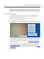
Compiling and Running the Project
After the PELCO camera page has been created in your project, compile and run the
project. Once the project is running, update your Page List from the Pages menu and
then navigate to the new camera page.
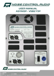
1. Click the IP Address button and enter the IP address of the camera.
2. Enter the other required camera properties.
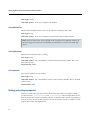
3. Click the Connect button and the PELCO Viewer should be connected to the camera
as below:
A pan, tilt and zoom toolbar and popup menu are provided to control the PELCO PTZ
cameras. Right-click the viewer window and choose to show the toolbar. The PELCO
PTZ camera can also be controlled by using the mouse. Click and hold the left mouse
button, and move the mouse to control the camera. See PELCO Viewer Mouse Controls
for more information.
It is now possible to view the live video and control the PELCO camera using the builtin pan, tilt and zoom controls such as toolbar buttons, mouse and popup menus. See
Pan, Tilt and Zoom Toolbar for more information. Cameras can also be controlled using
customised buttons. Some examples of custom control buttons can be seen in the PELCO
example project.
27
Chapter 3: Connecting to a PELCO Camera from a Project
Using Cicode
A PELCO camera control can be created and the camera controlled using Cicode functions. The PELCO Viewer ActiveX Control comes with a group of programming interfaces which can be accessed via Cicode. The two examples below demonstrate how to
use Cicode to control your camera through the programming interface.
Example
In this example, a Cicode command is embedded in a Button object named Left that will
control the camera to pan left at runtime.
The Cicode command for the button down input is:
_ObjectCallMethod(ObjectByName("PELCOCam"), "PanLeft");
The Cicode command for the button up input is:
_ObjectCallMethod(ObjectByName("PELCOCam"), "PanStop");
In this case, when the button is clicked, the camera will pan to the left. The pan left operation stops when your button is released. “PELCOCam” used in the Cicode function is
the object name assigned to the PELCO Viewer ActiveX Control object on the page of
your project.
Example
In this example, two Cicode functions are defined that do the same job as the example
above.
FUNCTION RunPanLeft()
OBJECT hPELCOPTZ =
_ObjectCallMethod(
END
FUNCTION RunPanStop()
OBJECT hPELCOPTZ =
_ObjectCallMethod(
END
28
ObjectByName("PELCOCam");
hPELCOPTZ, "PanLeft");
ObjectByName("PELCOCam");
hPELCOPTZ, " PanStop");
Chapter 3: Connecting to a PELCO Camera from a Project
Saving settings between page transitions
When you set properties on the PELCO Viewer control from Cicode and move off the
page, your changes will be lost. This behavior is not always what you want, so the
Graphics Builder provides a "Persist ActiveX data between page transitions" option to
save the state of an ActiveX control when you switch between pages.
Enabling this option causes SCADA to write a temporary file to the Data directory in the
format of <Event class>.stg whenever you leave a page that contains an ActiveX object
(for example, the PELCO Control). When you reenter the page, SCADA looks for that
same file and, if found, will load the settings from it. These files only exist while SCADA
run time is running. When you shut down SCADA, the temporary *.stg files are deleted.
To save between page transitions:
1. Double-click the PELCO ActiveX control you want to change. The Properties dialog
box appears.
2. Click the Access tab.
3. Click the Identification tab. The Identification panel appears.
4. In the Persistence area, select the Persist ActiveX data between page transitions check
box, and then click Apply.
29
Chapter 3: Connecting to a PELCO Camera from a Project
30
Chapter 4: PELCO Example Project
To test the PELCO cameras in the SCADA system, a PELCO Example Project has been
included in the installation. Example projects are provided in XP Style (Compatible with
v7, v7.10 and v7.20) and Tab Style (v7.20). They can be found in the Projects sub folder
of your chosen installation folder. After the project has been restored and compiled, enter
the connection details on the page and connect to the camera. The PELCO Example
project gives examples of one, two and four cameras, the Sarix camera, and Camera
Management. Some genies have been developed to help you get started. The project can
be expanded to cover more cameras and the genies can be reused in your own projects.
The PELCO PTZ toolbar and popup menu are provided to control the camera(s) position, as well as mouse and customized control buttons.
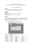
PELCO Camera Management page
The PELCO Camera Management page can be used to add or edit PELCO camera information such as name, description, IP address, port, number, RTSP mode, RTSP URL and
bandwidth. Camera information is stored in the database files in the projects folder. This
functionality can also be used to test the camera video stream in order to make sure the
information is valid after camera information is added or edited.
Camera Alarm Link
Alarm link provides a convenient way of integrating the alarm system and PELCO PTZ
cameras. The key to implementing a PELCO camera link is to use Cicode to run the “Preset” method provided by the PELCO Viewer ActiveX Control programming interface. An
example is provided to demonstrate this feature.
Example
In this example, there is a PELCO PTZ camera in the front entrance of an office and a
PIR (sensor) installed to trigger the alarm.
To configure the Alarm Link
1. Configure the camera’s preset (for example, 15) to point to the front entrance where
the PIR (sensor) will be triggered when the area is armed or secured.
2. Create a digital alarm tag (for example, PIRTrigged).
31
Chapter 4: PELCO Example Project
3. Create a digital alarm.
4. Add a Cicode function as below:
FUNCTION FrontEntranceAlarmLink()
OBJECT hPELCOPTZ = ObjectByName("PELCOCam");
INT preset = 15;
IF PIRTrigged = 1 THEN
_ObjectCallMethod( hPELCOPTZ, "PresetRun", preset );
END
END
5. If necessary, add a button to toggle the alarm at runtime.
6. Save, compile and run the project.
7. Open the camera page.
8. Make sure the camera is not pointing to the previously configured preset.
9. Trigger the alarm and check the change in the PELCO Viewer.
Genies
To simplify project creation, additional genies have been included in the example project
for:
l
function - used to call functions inside the ActiveX control on the one camera page.
l
setValue - used to create buttons and text objects to change the properties of the
PELCO camera.
l
pelcoCameraSelector - used to manage multiple cameras on the PELCO Camera
Management page.
See the PELCO Example Project for examples of these genies.
32
Chapter 5: Further Viewer Features
The PELCO Viewer includes the following features:
l
Pan, Tilt and Zoom controls
l
Popup menu controls
l
Mouse Controls
l
RTSP and Sarix Cameras
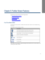
Pan, Tilt and Zoom toolbar
The PELCO Viewer includes a toolbar which allows the camera to be controlled using
the mouse.
The toolbar has the following controls:
Icon
Description
These controls enable the camera to Pan right or left (P)
These controls enable the camera to Tilt up or down (T)
Stop the Pattern, Tour, Scan and Pan or Tilt operations
Move the camera to the home position
Zoom near/far (Z)
Focus near/far
Iris close/open
This toolbar can be hidden by right-clicking the mouse button in the viewer window and
checking Show/Hide Toolbar.
33
Chapter 5: Further Viewer Features
CAMERA CONTROL CONFLICT
l
l
If the PELCO cameras are being controlled exclusively through the SCADA system then
ensure your SCADA system is designed to allow only one operator to perform operations
on a camera at a time.
If the PELCO cameras are being controlled independently by multiple systems (e.g
SCADA and Security) then ensure you have a clear documented and communicated process in place to ensure no camera conflict occur.
Failure to follow these instructions can result in death, serious injury, or equipment damage.
Popup Menu Controls
The popup menu toolbar allows additional controls and configuration of camera features. Right click the PELCO Viewer to display the following options:
Pattern Operation:
The Pattern menu will appear when connected to a SpectraIV camera.
l
Pattern > Run... - Runs the specified pattern
l
Pattern > Record... - Begins recording a new pattern
l
Pattern > End Record - Stops the current recording process
Click the Stop button in the PTZ Toolbar to stop the Pattern Operation.
Preset Operation:
The Preset menu will appear when connected to a camera equipped with PTZ functions.
l
Preset > Run... - Runs the specified preset
l
Preset > Set... - Sets the selected preset to the current camera position
l
Preset > Delete... - Deletes the specified preset
l
Preset > Home - Runs the currently configure home preset
l
Preset > Configure Home Preset... - Allows specification of which preset represents
the home position
Note: The number of presets that can be configured from PELCO ActiveX is 1-256
(based on the camera preset limit).
34
Chapter 5: Further Viewer Features
Scan operation:
The Scan menu will appear when connected to a SpectraIV camera equipped with PTZ
functions. There are three built in scan sequences: auto, random and frame. The default
is auto, which is a sequential scan.
l
Scan > Scan Random - Continuously rotates the camera horizontally in random increments. Random scan, being random in nature, can take several seconds to commence
l
Scan > Scan Frame - Continuously rotates the camera horizontally in 90 Degree increments
l
Scan > Scan Auto - Continuously rotates the camera 360 degrees
Click the Stop button in PTZ Toolbar to stop the scan operation.
Tour operation:
The Tour menu will appear when connected to a Sarix camera equipped with PTZ functions.
l
Tour > Run... - Runs the specified tour
Click the Stop button in the PTZ Toolbar to stop the Tour Operation.
Note: Tours must be created using the camera's web interface. For more information,
please refer to the PELCO Spectra HD camera user manual. When creating the Tour
from the web interface you must follow a strict naming convention in order to run
the Tour from the PELCO Viewer. The tour name must contain and start with the
(case-insensitive) word "Endura" AND a number afterwards. The Tour names must
end in a digit and the set of all digits must be consecutively numbered starting at 1.
Tour Name Examples: Endura Tour 1, Endura Tour 2, Endura Tour 3
Other Operations:
The Operation menu will appear when connected to a SpectraIV camera.
l
Operations > Rotate 180 Degrees - Pans the camera 180 degrees from its present position.
l
Operations > Pan to Zero - Pans the camera back to the camera's zero position. This
is not necessarily the same as the home position for the camera.
Hide Toolbar controls:
Show/Hide Toolbar
35
Chapter 5: Further Viewer Features
Hide Status Bar:
Show/Hide Status Bar
PELCO Viewer mouse controls
The PELCO Viewer allows the camera to be directly moved using mouse controls:
Click and hold the left mouse button:
l
Move the mouse left to move the camera to the left
l
Move the mouse right to move the camera to the right
l
Move the mouse up to move the camera up (if the Reverse Tilt check box is clicked
the camera will move down instead)
l
Move the mouse down to move the camera down (if the Reverse Tilt check box is
clicked the camera will move up instead)
Use the mouse scroll wheel to zoom the camera near and far.
Note: Mouse controls for Spectra HD Sarix cameras may have slow response times.
To avoid this, use the buttons on the toolbar instead.
RTSP and Sarix cameras
Real Time Streaming Protocol, or RTSP, is an application-level protocol for control over
the delivery of data with real-time properties. RTSP provides an extensive framework to
enable controlled, on-demand delivery of real-time data such as video. Sources of data
can include both live data feeds and stored clips. This protocol is intended to control
multiple data delivery sessions, provide a means for choosing delivery channels, such
as UDP, multicast UDP or TCP, and provide a means for choosing delivery mechanisms
based on RTP (RFC 1889).
Sarix cameras have an RTSP server in the camera and the current PELCO Viewer ActiveX control supports both RTP and RTSP.
The SarixCamera page in the example project is designed for a Sarix camera.
36
Part: 2
Reference
This section describes the properties and methods used to access and
control PELCO cameras from within SCADA. In addition it provides
a troubleshooting section to help investigate loss of connection with
your cameras.
PELCO Viewer ActiveX Control interface properties
PELCO Viewer ActiveX Control interface methods
Troubleshooting
37
38
Chapter 6: PELCO Viewer ActiveX Control Interface Properties
The following properties can be used to manage and control PELCO IP cameras in various ways, from video streaming, PTZ control speed and other properties at SCADA runtime. See "PELCO Viewer ActiveX Control Interface Properties"
Property
Description
AutoConnect
Connects to configured camera when page is loaded in runtime
Bandwidth
Returns the streaming video bandwidth constraints.
CameraNumber
Changes the active camera being viewed on a DVR.
CameraIpAddress
The IP address of the PELCO device where video is streamed
from.
CameraPortNumber
The port number of the camera.
HomePresetId
Camera preset ID used for the home position/button on the PTZ
control.
ReverseTilt
Reverses the tilt direction when using the mouse.
RtspMode
Specifies RTP camera or RTSP camera.
RtspUrl
Specifies the RTSP URL if the camera is a RTSP camera.
UnicastStream
Specifies whether unicast or muliticast
UnicastStreamIP
The IP address of your local computer that the PELCO device will
stream the video to.
UnicastStreamPort
The port that the PELCO device will use for unicast listening in for
the video.
VelocityHorizontal
The horizontal rotation velocity setting.
VelocityVertical
The vertical rotation velocity setting.
39
Chapter 6: PELCO Viewer ActiveX Control Interface Properties
Properties
To be able to connect to a PELCO camera from the PELCO Viewer ActiveX control at runtime, the camera connection information must be specified to an object in the PELCO
Viewer ActiveX control. When setting properties via Cicode, the values will not be persisted when you navigate away from the page and they will need to be set again when
you re-open the page. You can have the last values automatically set either using tags
(see Tag Association) or using the “Persist ActiveX data between page transitions”
option.
Listed below are the properties of the PELCO Viewer ActiveX Control interface in this
release.
AutoConnect
This property causes a configured camera to be automatically connected when the page
is loaded in runtime. Set to "1" to enable auto connection.
Data Type: Digital
Allowable Values:
l
0 - AutoConnect property is Off
l
1 - AutoConnect property is On
Default Value: 0
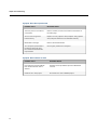
Bandwidth
Returns the streaming video bandwidth constraints. The higher the bandwidth, the
better the image quality, the greater the processing power, but the network traffic will
also be greater.
There are three factors that affect bandwidth:
40
l
The total number of cameras connected
l
The motion type (low, medium, high) – A camera transmits actual frames and delta
frames so the more the image changes, the higher bandwidth used
l
Bandwidth type - There are three types of bandwidth setting in PELCO Viewer:
Bandwidth Settings
Frames/Sec
Bit Rate
Gop (Group of Picture)
High
30
2,000,000
15
Medium
30
150,000
15
Chapter 6: PELCO Viewer ActiveX Control Interface Properties
Bandwidth Settings
Frames/Sec
Bit Rate
Gop (Group of Picture)
Low
30
198
15
For more information regarding bandwidth/network performance see UnicastStream
property.
Data Type: Long
Allowable Values:
l
0 - High Bandwidth
l
1 - Medium Bandwidth
l
2 - Low Bandwidth
Default Value: 0
CameraNumber
Changes the active camera being viewed on a DVR. Set this value to 1 for normal IP
cameras.
Data Type: Long
Allowable Values: Any valid PELCO camera number.
Default Value: 1
CameraIpAddress
The IP address of the PELCO device where video is streamed from.
Data Type: String
Allowable Values: Any valid PELCO camera IP address.
Example: 192.168.0.90
CameraPortNumber
The port number of the camera.
Data Type: Long
Allowable Values: Any valid PELCO camera port number.
Default Value: 49152
41
Chapter 6: PELCO Viewer ActiveX Control Interface Properties
HomePresetId
Camera preset ID used for the home position/button on the PTZ control.
Data Type: Int
Allowable Values: Any valid PELCO camera preset number.
Default Value: 3
ReverseTilt
This property allows the user to reverse the tilt direction when using the mouse during
RTP streaming.
Data Type: Digital
Allowable Values:
l
0 – Reverse Tilt property is Off
l
1 – Reverse Tilt property is On
Default Value: 0
RtspMode
Specifies the type of camera connected, either RTP or RTSP.
Data Type: Int
Allowable Values:
l
0 - RTP camera
l
1 - RTSP camera
Default Value: 0
RtspUrl
Provides the RTSP URL if the camera is a RTSP camera. Dependent on the configuration
of the RTSP camera.
Data Type: String
Allowable Values: Any valid PELCO Sarix camera URL.
Example: rtsp://192.168.0.18/stream1
42
Chapter 6: PELCO Viewer ActiveX Control Interface Properties
UnicastStream
Specifies either a unicast or multicast streaming type.
Unicast
A unicast connection sends a separate video stream from the camera to each Pelco
Viewer (client). Although multiple Pelco Viewers might request the same data from the
camera at the same time, a unique, separate video stream is transmitted to each Pelco
Viewer.
Every unicast connection to the camera consumes additional processing power which
limits the number of simultaneous clients which can access the camera.
PELCO cameras support a maximum of 20 simultaneous clients.
Multicast
A multicast connection sends a video stream to multiple PELCO Viewers (clients) at the
same time using one, shared transmission stream. Unlike unicast, multicast communication requires much less processing power for the camera, instead your network
design and the type of network switches used are the important factors in the number of
clients that can be supported and the performance of your system. Multicast is useful
only for local area networks and can be used to preserve network bandwidth.
For more information about network, bandwidth and Switch Compatibility related information please see Endura Network Design Guide and Endura Switch Compatibility
When using multi-cast please be aware that the video stream is sent to your primary network adapter. If you are running virtualization software on your machine it may prevent the video stream from being sent to your primary network adapter. Please see
Troubleshooting for more information.
When a unique connection to the camera is required then select the unicast option and
provide your computer's Local IP address and valid port details. The video will be
streamed to this IP address. If this property is false then multicast streaming will be
established.
Data Type: Digital
Allowable Values:
l
0 - Unicast Stream Off (Unicast Stream IP and port will be ignored)
l
1 - Unicast Stream On
Default Value: 0
UnicastStreamIP
The IP address of your local computer to which the PELCO device will stream the video.
43
Chapter 6: PELCO Viewer ActiveX Control Interface Properties
Data Type: String
Allowable Values: Your local computer’s IP address
UnicastStreamPort
The port that the PELCO device will use for Unicast listening for the video.
Data Type: Long
Allowable Values: Your local computer’s port number used for video stream.
Note: Unicast stream port values should not be consecutive for different cameras on
the same page because the next immediate port numbers are reserved for PTZ operations.
VelocityHorizontal
The horizontal rotation velocity setting.
Data Type: Long
Allowable Values: Any valid PELCO camera horizontal velocity number. This is for
PTZ cameras only.
Default Value: 64000
VelocityVertical
The vertical rotation velocity setting.
Data Type: Long
Allowable Values: Any valid PELCO camera vertical velocity number. This is for PTZ
cameras only.
Default Value: 8000
Reading and writing to properties
Properties listed in the previous section can be read and written at runtime with the
Cicode functions _ObjectGetProperty and _ObjectSetProperty. The example below shows
how to modify the camera’s horizontal velocity at runtime. If the camera is panning too
slow or too fast, increase or decrease the camera’s horizontal velocity at runtime accordingly to personalise the requirements.
44
Chapter 6: PELCO Viewer ActiveX Control Interface Properties
Example
Where "PELCOCam" is the object name of a PELCO Viewer ActiveX Control instance
inserted on a graphics page.
FUNCTION SetVelocityHorizontal()
OBJECT hPELCOPTZ = ObjectByName("PELCOCam");
INT oldSpeed = _ObjectGetProperty(hPELCOPTZ,"VelocityHorizontal");
INT newSpeed = StrToInt(Input("Velocity Horizontal", "Enter pan speed", oldSpeed));
_ObjectSetProperty( hPELCOPTZ, "VelocityHorizontal", newSpeed );
END
45
Chapter 6: PELCO Viewer ActiveX Control Interface Properties
46
Chapter 7: PELCO Viewer ActiveX Control Interface Methods
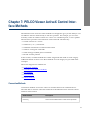
The PELCO Viewer ActiveX Control methods are designed to give you the ability to control PELCO cameras automatically as much as possible. For example, you can automatically switch to another camera in a viewer or to a different preset, or run a pattern.
The list below provides some tasks that can be achieved automatically:
l
Switch cameras in a viewer
l
Send focus (+ or --) commands
l
Send PTZ commands to a PELCO PTZ camera
l
Send iris close/open commands
l
Send create/go to/delete preset commands
l
Record and run patterns
In this section, available methods have been categorised and listed for each category.
Additional details on how to use these methods in each category are provided in the
examples.
The main categories for methods are:
l
Connection methods
l
Customize User Interface methods
l
PTZ methods
l
Preset methods
l
Pattern methods
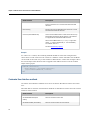
Connection Methods
Connection methods are used to connect to and disconnect from a PELCO device.
The table below contains connection methods for the PELCO Viewer ActiveX Control
interface in this release.
Method Name
Description
Connect()
Connect to the PELCO device video stream specified
47
Chapter 7: PELCO Viewer ActiveX Control Interface Methods
Method Name
Description
by the properties. It is used for both RTP and RTSP
cameras.
Disconnect()
Disconnect from the PELCO device stream. It is used
for both RTP and RTSP cameras.
Connect(CameraBandwith)
Connect to the PELCO device video stream and set up
bandwidth specified by the Properties. This method
is supported for both RTP & RTSP streams.
Where CameraBandwith is 0, 1 or 2 (0 - high bandwidth, 1 - medium bandwidth, 2 - low bandwidth).
The default value is 0.
See also Bandwidth property.
Example
To connect to a camera, the Connect() method should be used. The example below
shows how Cicode can be used to connect to a PELCO camera. The other two methods
can be used in the same way as this method. "PELCOCam" used in the example code is
the actual object name that has been assigned to the PELCO Viewer ActiveX Control
object in this project.
FUNCTION ConnectCamera()
OBJECT hPELCOCam = ObjectByName("PELCOCam");
_ObjectCallMethod(hPELCOCam, "Connect");
END
Customize User Interface methods
Customize User Interface methods are used to customize the PELCO Viewer user interface.
The table below contains customization methods for the PELCO Viewer ActiveX Control
interface in this release.
48
Method Name
Description
ShowHideStatusbar(bool
status)
Show or hides the status-bar
ShowHideToolbar(bool status)
Show or hides tool-bar for PTZ cameras
Chapter 7: PELCO Viewer ActiveX Control Interface Methods
PTZ Methods
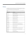
PTZ methods are used to pan, tilt and zoom a PELCO PTZ camera and are not applicable to fixed cameras. If the camera supports it, it can also change the focus and iris on
any camera that support those functions programmatically.
The table below contains the PTZ methods for PELCO Viewer ActiveX Control in this
release.
Method Name
Description
PanLeft()
Start panning the camera to the left. PanStop() is required to
stop the camera panning.
PanRight()
Start panning the camera to the right. PanStop() is required
to stop the camera panning.
PanUp()
Start tilting the camera up.
PanDown()
Start tilting the camera down.
PanStop()
Stop panning the camera.
ZoomIn()
Start zooming the camera in.
ZoomOut()
Start zooming the camera out.
ZoomStop()
Stop zooming the camera.
FocusNear()
Start focusing the camera on objects that are closer.
FocusFar()
Start focusing the camera on objects that are farther.
FocusStop()
Stop focusing the camera.
FocusAuto()
Auto-focus the camera.
IrisOpen()
Start opening the camera's iris to brighten the image.
IrisClose()
Start closing the camera's iris to darken the image.
IrisStop()
Stop resizing the iris.
IrisAuto()
Auto-adjust the camera iris.
49
Chapter 7: PELCO Viewer ActiveX Control Interface Methods
When a pan method is called, for example PanLeft, it will continue to run until a PanStop method is called.
LOSS OF CONTROL
Ensure PanStop is called when PanLeft or PanRight methods are used.
Failure to follow these instructions can result in death, serious injury, or equipment damage.
Note: PanLeft and PanRight methods require PanStop to be called to stop the camera
from continuously panning.
Example
An example has been provided below on how to use the PanLeft method to pan a PTZ
camera left for 10 seconds and then stop the operation. Any other PTZ methods can be
used in the same way as this method. "PELCOCam" used in the example code is the
actual object name that has been assigned to the PELCO Viewer ActiveX Control object
in this project.
FUNCTION PanCameraLeft()
OBJECT hPELCOCam = ObjectByName("PELCOCam");
_ObjectCallMethod(hPELCOCam, "PanLeft");
SleepMS(10000);
_ObjectCallMethod(hPELCOCam, "PanStop");
END
Preset Methods
The preset methods are used to manage and run presets on a PELCO PTZ camera and
are not applicable to fixed cameras. Home is also a special preset in the PTZ camera. It
is also possible to set the Home position and point the camera to the Home position that
has been selected for the camera.
The table below contains preset methods for the PELCO Viewer ActiveX Control interface in this release.
50
Chapter 7: PELCO Viewer ActiveX Control Interface Methods
Method Name
Description
PresetDelete( long presetId )
Deletes the specified preset ID.
PresetSet( long presetId )
Stores the current camera position (pan/tilt) and zoom
level at the specified preset ID.
PresetHomeSet()
Stores the current camera position and zoom level as the
home preset ID (defaults to preset ID 3)
This is the Preset ID that is run when the Home button is
clicked.
PresetRun( long presetId )
Moves the camera to the location and zoom level stored
at the specified preset ID.
PresetHomeRun()
Moves the camera to the location and zoom level stored
in the home preset ID (defaults to preset ID 3).
This is the preset ID that is run when the Home button is
clicked.
Example
The example below shows how to use the PresetRun method to control the PTZ camera.
Other preset methods can be used in the same way as this method. In the example
below, a Cicode function has been written to run a preset position that has been programmed and stored into the PTZ camera. "PELCOCam" used in the example code is the
actual object name that has been assigned to the PELCO Viewer ActiveX Control object
in this project.
FUNCTION RunPreset()
OBJECT hPELCOCam = ObjectByName("PELCOCam");
INT preset = StrToInt(Input("Run Preset", "Enter the Preset number to Run", "1"
));
_ObjectCallMethod(hPELCOCam, "PresetRun", preset );
END
Example
In example below, the Cicode function demonstrates how to save the PTZ camera’s current position and settings as the Home position.
FUNCTION SaveHomePosition()
OBJECT hPELCOCam = ObjectByName("PELCOCam");
51
Chapter 7: PELCO Viewer ActiveX Control Interface Methods
_ObjectCallMethod(hPELCOCam, "PresetHomeSet" );
END
Pattern Methods
Pattern methods are used to record and run patterns on a PELCO PTZ camera and are
not applicable to fixed cameras.
The table below contains pattern methods for the PELCO Viewer ActiveX Control interface in this release.
Method Name
Description
PatternRun( long patternId )
Run the camera movement pattern specified by the pattern ID.
PatternStop( long patternId )
Stop the camera movement pattern specified by the pattern ID.
PatternStart( long patternId )
Start recording the camera movement pattern specified
by the pattern ID.
PatternEnd( long patternId )
End recording for the camera movement pattern specified by the pattern ID.
Note: If you use the PatternStart method to start recording a pattern, then a PatternEnd method must be used to end the recording. Also note that there is only one
pattern supported on some PELCO PTZ cameras in IP mode.
LOSS OF CONTROL
Ensure PatternStop is called when PatternStart() method is used.
Failure to follow these instructions can result in death, serious injury, or equipment damage.
52
Chapter 7: PELCO Viewer ActiveX Control Interface Methods
Example
The example below shows how to use the PatternRun method to run a pattern on the
PTZ camera. Other pattern methods can be used in the same way as this method. In the
example below, a Cicode function has been written to run a pattern previously recorded
and stored in the PTZ camera. "PELCOCam" used in the example code is the actual
object name that has been assigned to the PELCO Viewer ActiveX Control object in this
project.
FUNCTION RunPattern()
OBJECT hPELCOCam= ObjectByName("PELCOCam");
INT pattern = StrToInt(Input("Run Pattern", "Enter the Pattern Number to Run",
"1" ));
_ObjectCallMethod(hPELCOCam, "PatternRun", pattern );
END
53
Chapter 7: PELCO Viewer ActiveX Control Interface Methods
54
Chapter 8: Troubleshooting
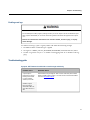
In this section, some guidelines and tips are provided for debugging on PELCO camera-related projects.
When working with PELCO Viewer ActiveX control, you will be able to see real time camera status in the
‘status bar' and additional information will be logged in the Windows ‘event viewer’. Enter the “eventvwr”
run command to launch the Event Viewer. For specific PELCO camera difficulties, please refer to your
PELCO camera's manual.
Devices and tools
Essential devices
In order to analyse functionality related to PELCO camera projects, you will need either
direct or indirect access to a PELCO IP or Sarix camera. Be aware that if the camera is
accessed over the Internet, you will experience poor streaming quality and very poor
responsiveness to the camera controls.
Essential tools/utilities
There are some tools and utilities recommended to assist in analysing the functionality
of PELCO camera on SCADA projects:
l
PELCO Device Utility – Assists in locating a PELCO camera IP address on your network.
l
PELCO Diagnostic Player – Tests camera video rendering on the system.
l
DXDIAG – Checks the DirectX version and sets and tests Direct3D acceleration on
your computer.
l
DESK.CPL – Checks dedicated on-board memory on your graphic card.
l
Wireshark – Checks network communication between your computer and PELCO
camera.
l
Intel UPnP Device spy – Locates the PELCO RTP camera IP address and port
number.
55
Chapter 8: Troubleshooting
Implementation checklist
Before debugging you system, please go through the checklist below to make sure that
the PELCO camera has been implemented optimally.
l
The Hardware and software requirements in the Installation Requirements have been
met or exceeded.
l
Only PELCO IP or Sarix cameras have been tested and are supported.
l
Only use a cable modem router or a switch with a DHCP server when installing
PELCO IP cameras on a network.
l
Do not use a HUB in the network setup of an IP camera.
l
Place PELCO cameras behind a firewall when they are connected to a network.
l
Install the latest version of the PELCO Viewer ActiveX Control.
Debugging procedure
Generally, there are three types of functions to analyse:
l
Camera hardware, setup or network related
l
PELCO Viewer ActiveX and its dependencies software setup/configuration related
l
PELCO Viewer ActiveX configuration/setup in SCADA projects during SCADA
project configuration or runtime
The procedure listed below will help you identify the type of issue and assist with debugging.
1. Is the camera a PELCO camera?
This manual addresses issues with PELCO cameras only.
2. Can you view the video stream in Internet Explorer?
If not, there may be an issue with the camera, installation or network.
3. Can you view the video stream in PELCO Diagnostic Player?
If not, there may be an issue with the PELCO Viewer installation. Re-install and configure the PELCO Viewer and try again.
4. Can you view the video stream in SCADA runtime?
If not, there may be some project related issue preventing access to the video stream.
Try to connect to the camera using the PelcoExample test project.
See the Troubleshooting Guide section for information.
56
Chapter 8: Troubleshooting
Enabling event logs
REGISTRY CORRUPTION
Do not attempt to modify registry settings unless you are an expert user of the Windows operating system and SCADA, or are under the direct guidance of technical support for this product.
Failure to follow these instructions can result in death, serious injury, or equipment damage.
To enable event logs, open a registry editor and make the following change:
1. In Windows Run Command type “regedit”
2. Navigate to “HKEY_LOCAL_MACHINE\SOFTWARE\Schneider Electric\Pelco”
3. Set the “Log Value” key to "1" to enable event logging and "0" to disable event logging.
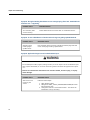
Troubleshooting guide
Symptom: .NET Framework 3.5 SP1 fails to install through web directly.
Possible Issue
Remedial Action
A port may be
blocked from downloading and installing the installer
directly from web.
Download the full package of .NET 3.5 SP1 manually and install it
before installing Pelco Viewer. The full version can be downloaded
from the Microsoft website.
Installer might
launch a link to
download .NET version other than 3.5
SP1
57
Chapter 8: Troubleshooting
Symptom: During Uninstalling PelcoViewer an error message saying “Error 1001: InstallUtilLib.dll.
Unknown error.” is appearing.
Possible Issue
Remedial Action
The necessary .NET
version missing.
Install .NET Framework 3.5 SP1 and un-install Pelco Viewer.
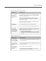
Symptom: In case of #COM errors or Runtime values for tags not getting updated/refreshed.
Possible Issue
Remedial Action
Sample project
restore/pages
update issues.
Run Computer Setup wizard or navigate to another page and then
return to the page causing update issues.
Symptom: Application hangs on some invalid IP address input.
REGISTRY CORRUPTION
Do not attempt to modify registry settings unless you are an expert user of the Windows operating system and SCADA, or are under the direct guidance of technical support for this product.
Failure to follow these instructions can result in death, serious injury, or equipment damage.
58
Possible Issue
Remedial Action
Web-service not
returning the
values.
Follow the below steps:
1. Open Registry editor.
2. Navigate to “HKEY_LOCAL_MACHINE\SOFTWARE\Schneider
Electric\Pelco” path
3. Change the value for “ConnectionTimeout”. The values can
be between 5-30(in seconds).
Chapter 8: Troubleshooting
Symptom: RTP camera has no video at runtime
Possible Issue
Remedial Action
Are the camera IP
address, port
number and camera number correct?
Use Intel UPnP Device spy to check your camera IP address and
port number. The port number usually has a default value 49152
and camera number should be 1.
If not, (if they are different from camera IP address and port
number reported by Intel UPnP Device spy), try the new IP
address and port number.
If yes, (they are the same), or there is still no video image when
trying the new values, then continue.
Is it working in
Web browser?
If no, refer to PELCO manual or contact PELCO support.
If yes, try connecting the camera from PELCO Diagnostic Playerr.
You are using
multi-cast and
have virtualization
software installed
such as VMWare.
Virtualization software typically installs its own software network
adapters on your machine. These adapters, if enabled, can steal
multi-cast traffic. Resolutions include:
1. Disable virtual network adapters
2. Use a unicast connection and specify your network adapter
3. Consult your virtualization software manufacturer for other
solutions
Symptom: PTZ too slow or fast
Possible Issue
Remedial Action
Does this happen
when using toolbar
PTZ control buttons?
If yes, this is by design and cannot be changed during runtime.
If no, please continue.
Does this happen
when using mouse
control?
If yes, this is by design and cannot be changed during runtime.
If no, please continue.
Does this happen
when using customized control or
Cicode?
If no, please refer to information above.
If yes, increase or decrease horizontal or vertical velocity to
adjust PTZ speed until you are satisfied.
59
Chapter 8: Troubleshooting
Symptom: PTZ control latency is too long
Possible Issue
Remedial Action
Image quality and
bandwidth too high
Reduce bandwidth.
Too many concurrent camera connections
Reduce number of concurrent camera connections.
Network traffic is too
heavy
Reduce unnecessary network traffic if possible.
Network too slow
Make sure the camera is within the local network. Improve network speed.
Symptom: Video streaming not working on Sarix camera
Possible Issue
Remedial Action
Is it working in
Web browser?
If no, please refer to PELCO manual or contact PELCO support.
If yes, try connecting the camera from PELCO Diagnostic Player.
Have you set
RtspMode property
to true at runtime?
If no, set RtspMode property to true (non-zero value) at runtime
and try again.
If yes, continue.
Have you set
RtspURL property
to correct value at
runtime?
60
If no, set RtspURL property to the correct value at runtime and try
again. The default format of this property is: Rtsp://Camera_IP_
Address/stream1
Chapter 8: Troubleshooting
Symptom: Two or more video streams not working on same page
Possible Issue
Remedial Action
Caused by conflicting object
names assigned to the
PELCO Viewer ActiveX Control object
Rename conflicted object name assigned to the PELCO
Viewer ActiveX Control object
Caused by conflicting object
names used in Cicode Connect function
Rename conflicted object name used in Cicode Connect
function
Caused by conflicting unicasting port numbers
Resolve conflicted uni-casting port number. Any unicasting port number can only be used once.
Symptom: Poor image quality
Possible Issue
Remedial Action
Image is not
focused
Adjust focus
Bandwidth is too
low
Increase camera bandwidth
There is not
enough dedicated
memory
Replace current graphics card/computer with graphics card/computer that has more dedicated memory
61
Chapter 8: Troubleshooting
Symptom: Slow video responsiveness
Possible Issue
Remedial Action
Too many concurrent camera
connections
Reduce number of concurrent camera connections on
the same page
There is not enough dedicated memory
Replace current graphics card/computer with graphics
card/computer that has more dedicated memory
Bandwidth is too high
Reduce camera bandwidth
The computer specification is
too low and does not meet
the recommended hardware
requirements
Use a higher performance computer
Symptom: Alarm link does not work
62
Possible Issue
Remedial Action
Preconfigured preset in PELCO
PTZ camera has been lost or
deleted.
Reconfigure the predefined preset in PELCO PTZ
camera.
Cicode error in the project
Fix Cicode error in the SCADA project.
Glossary
A
ActiveX
A framework for defining reusable software components that perform a particular function or set of
functions in Microsoft Windows in a way that is independent of the programming language used to
implement them. A software application can then be composed of one or more of these components
in order to provide its functionality.
D
DVR
Digital Video Recorder
I
Iris
A mechanical device found in cameras that mimics the function of the biological iris.
P
PELCO camera
In this document, PELCO camera refers to PELCO IP cameras and PELCO Sarix cameras.
PELCO device
In this document, PELCO device refers to PELCO RTP and RTSP cameras.
PTZ
Pan, Tilt and Zoom
R
RAM
Random Access Memory
RTP
Real-Time Transport Protocol
63
Glossary
RTSP
Real-Time Streaming Protocol
S
Sarix
A new camera imaging technology developed by Pelco
SCADA
Supervisory Control and Data Acquisition. In this document, SCADA refers to Vijeo Citect, CitectSCADA or CitectFacilities
64
D
Index
#
#COM issues
58
A
ActiveX control, installing
adding buttons
Alarm link issues
AutoConnect property
18
26
62
40
B
Bandwidth property
buttons, adding
buttons, connect and disconnect
40
26
26
C
camera availability
20
camera control with Cicode
28
camera control, with mouse
36
camera management page, example project
31
camera number
20
camera port number
20
camera preset positions
34
camera properties
26, 40
camera properties, reading and writing
44
camera scan sequences
35
camera tour operations
35
camera, configuring in design time
24
CameraNumber property
41
cameras
RTSP & Sarix
36
supported
13
Cicode, controlling the camera
28, 47
concurrent video streams
17
Connect() method
47
connecting to a camera
26
control methods
47
controlling the camera with mouse
36
controls, adding
26
debugging checklist
debugging procedure
DirectX
Disconnect() method
disconnecting from a camera
DXDIAG
56
56
16
47
26
55
E
example project
camera management page
31
31
F
FocusAuto() method
FocusFar() method
FocusNear() method
FocusStop() method
49
49
49
49
G
genie
function
pelcoCameraSelector
SetValue
graphic card memory
graphics pages, defining
32
32
26, 32
18
23
H
hardware requirements
HomePresetID prroperty
16
42
I
image quality issues
implementation checklist
install issues
installation
verifying
invalid IP address
IP address
IPAddress property
IrisAuto() method
IrisClose() method
IrisOpen() method
IrisStop() method
61
56
57
15
18
58
20
41
49
49
49
49
M
mapping tags
26
65
Index
memory, graphic card
methods
connection
customize
pattern
preset
PTZ
mouse controls
multiple video stream issues
18
47
48
52
50
49
36
61
N
no video at runtime
59
O
operating system requirements
15
P
PandDown() method
49
PanLeft() method
49
panning
33
PanRight() method
49
PanStop() method
49
PanUp() method
49
pattern, methods
52
pattern, recording
34
PatternEnd(patternID) method
52
PatternRun(patternID) method
52
PatternStart(patternID) method
52
PatternStop(patternID) method
52
PELCO camera usage
13
PELCO Device Utility
21, 55
PELCO Diagnostic Player
18, 55
PELCO Viewer, adding
23
pelcoCameraSelector genie
32
Persist ActiveX data between page transitions 29
port number, camera
20
Port property
41
preset methods
50
PresetDelete(presetID) method
50
PresetHomeRun() method
50
PresetHomeSet() method
50
PresetRun(presetID) method
50
presets
34
PresetSet(presetID) method
50
project, compiling
27
project, testing
27
66
PTZ
PTZ
PTZ
PTZ
latency issues
methods
too slow or fast
toolbar
60
49
59
33
reading camera properties
requirements
hardware
operating system
software
video streaming
return to zero position
reverse camera position
ReverseTilt prroperty
RTSP cameras
RtspMode property
RtspUrl property
44
R
16
15
15
17
35
35
42
36
42
42
S
Sarix cameras
Sarix streaming not working
scan sequences
SetValue genie
ShowHideStatusbar(status) method
ShowHideToolbar(status) method
Slow video stream
software requirements
status bar, show/hide
supported cameras
36
60
35
26, 32
48
48
62
15
36
13
T
tags, mapping
tilting
toolbar, pan, tilt and zoom
toolbar, show/hide
tours
troubleshooting
26
33
33
35
35
57-59
U
UnicastStream property
UnicastStreamIP property
UnicastStreamPort property
uninstall issues
43
43
44
58
V
VelocityHorizontal property
44
Index
VelocityVertical property
video streaming requirements
44
17
W
writing camera properties
44
Z
zero position
ZoomIn() method
zooming
ZoomOut() method
ZoomStop() method
35
49
33
49
49
67
Index
68