1
USER'S MANUAL
FX3U-32DP PROFIBUS-DP Interface Block
Safety Precautions
(Read these precautions before use.)
Before installation, operation, maintenance or inspection of this product, thoroughly read through and
understand this manual and all of the associated manuals. Also, take care to handle the module properly and
safely.
This manual classifies the safety precautions into two categories:
and
.
Indicates that incorrect handling may cause hazardous conditions, resulting in
death or severe injury.
Indicates that incorrect handling may cause hazardous conditions, resulting in
medium or slight personal injury or physical damage.
Depending on the circumstances, procedures indicated by
may also cause severe injury. It is
important to follow all precautions for personal safety.
Store this manual in a safe place so that it can be taken out and read whenever necessary. Always forward it
to the end user.
1. DESIGN PRECAUTIONS
Reference
Page
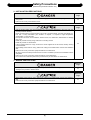
• Make sure to have the following safety circuits outside of the PLC to ensure safe system operation
even during external power supply problems or PLC failure.
Otherwise, malfunctions may cause serious accidents.
1) Most importantly, have the following: an emergency stop circuit, a protection circuit, an
interlock circuit for opposite movements (such as normal vs. reverse rotation), and an interlock
circuit (to prevent damage to the equipment at the upper and lower positioning limits).
2) Note that when the PLC CPU detects an error, such as a watchdog timer error, during selfdiagnosis, all outputs are turned off. Also, when an error that cannot be detected by the PLC
CPU occurs in an input/output control block, output control may be disabled.
External circuits and mechanisms should be designed to ensure safe machinery operation in
such a case.
3) Note that when an error occurs in a relay, triac or transistor output device, the output could be
held either on or off.
For output signals that may lead to serious accidents, external circuits and mechanisms
should be designed to ensure safe machinery operation in such a case.
19
23
Reference
Page
• Make sure to observe the following precautions in order to prevent any damage to the machinery
or accidents due to abnormal data written to the PLC under the influence of noise:
1) Do not bundle the main circuit line together with or lay it close to the main circuit, high-voltage
line, or load line. Otherwise, noise disturbance and/or surge induction are likely to take place.
As a guideline, lay the control line at least 100mm (3.94") or more away from the main circuit,
high-voltage line, or load line.
2) Ground the shield wire or shield of the shielded cable at one point on the PLC. However, do
not ground them at the same point as the high-voltage lines.
• Install module so that excessive force will not be applied to peripheral device connectors.
Failure to do so may result in wire damage/breakage or PLC failure.
(i)
19
23
27
Safety Precautions
(Read these precautions before use.)
2. INSTALLATION PRECAUTIONS
Reference
Page
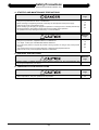
• Make sure to cut off all phases of the power supply externally before attempting installation or
wiring work.
Failure to do so may cause electric shock.
23
Reference
Page
• Use the product within the generic environment specifications described in the PLC main unit
manual (Hardware Edition).
Never use the product in areas with dust, oily smoke, conductive dusts, corrosive gas (salt air, Cl2,
H2S, SO2, or NO2), flammable gas, vibration or impacts, or exposed to high temperature,
condensation, or wind and rain.
If the product is used in such conditions, electric shock, fire, malfunction, deterioration or damage
may occur.
• Install the product securely using a DIN rail or mounting screws.
• Install the product on a flat surface.
If the mounting surface is rough, undue force will be applied to the PC board, thereby causing
nonconformities.
• When drilling screw holes or wiring, make sure cutting or wire debris does not enter the ventilation
slits.
Failure to do so may cause fire, equipment failures or malfunctions.
• Be sure to remove the dust proof sheet from the PLC's ventilation port when the installation work is
completed.
Failure to do so may cause fire, equipment failures, and malfunctions.
• Do not touch the conductive parts of the product directly to avoid failure or malfunctions.
23
3. WIRING PRECAUTIONS
Reference
Page
• Cut off all phases of the power supply externally before installation or wiring work in order to avoid
damage to the product or electric shock.
27
Reference
Page
• When drilling screw holes or wiring, make sure cutting or wire debris does not enter the ventilation
slits.
Failure to do so may cause fire, equipment failures or malfunctions.
(ii)
27
Safety Precautions
(Read these precautions before use.)
4. STARTUP AND MAINTENANCE PRECAUTIONS
Reference
Page
• Do not touch any terminal while the PLC’s power is on.
Doing so may cause electric shock or malfunctions.
• Before cleaning or retightening terminals, externally cut off all phases of the power supply.
Failure to do so may cause electric shock.
• Before modifying or disrupting the program in operation or running the PLC, carefully read through
this manual and the associated manuals and ensure the safety of the operation.
An operation error may damage the machinery or cause accidents.
19
53
57
65
Reference
Page
• Do not disassemble or modify the unit.
Doing so may cause fire, equipment failures, or malfunctions.
* For repair, contact your local Mitsubishi Electric distributor.
• Do not drop the product or expose the product to strong impacts, as doing so may cause product
damage.
• Turn off the power to the PLC before attaching or detaching the peripheral devices.
Failure to do so may cause equipment failures or malfunctions.
19
53
57
65
5. DISPOSAL PRECAUTIONS
Reference
Page
• Please contact a certified electronic waste disposal company for the environmentally safe
recycling and disposal of your device.
20
6. TRANSPORTATION PRECAUTIONS
Reference
Page
• The PLC and peripheral devices are precision instrument. During transportation, avoid impacts.
After transportation, verify the operations of the products.
(iii)
20
(iv)
FX3U-32DP PROFIBUS-DP Interface Block
User’s Manual
FX3U-32DP PROFIBUS-DP Interface Block
User’s Manual
Manual number
JY997D25201
Manual revision
A
Date
03/2007
Foreword
This manual contains text, diagrams and explanations which will guide the reader in the correct installation,
safe use and operation of the FX3U-32DP and should be read and understood before attempting to install or
use the unit.
Store this manual in a safe place so that you can take it out and read it whenever necessary. Always forward
it to the end user.
This manual confers no industrial property rights or any rights of any other kind, nor does it confer any patent
licenses. Mitsubishi Electric Corporation cannot be held responsible for any problems involving industrial property
rights which may occur as a result of using the contents noted in this manual.
© 2007 MITSUBISHI ELECTRIC CORPORATION
1
FX3U-32DP PROFIBUS-DP Interface Block
User’s Manual
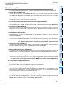
Outline Precautions
• This manual provides information for the use of the FX3U-32DP. The manual has been written to be used
by trained and competent personnel. The definition of such a person or persons is as follows;
a) Any engineer who is responsible for the planning, design and construction of automatic equipment
using the product associated with this manual should be of a competent nature, trained and qualified
to the local and national standards required to fulfill that role. These engineers should be fully aware of
all aspects of safety with regards to automated equipment.
b) Any commissioning or service engineer must be of a competent nature, trained and qualified to the
local and national standards required to fulfill that job. These engineers should also be trained in the
use and maintenance of the completed product. This includes being completely familiar with all
associated documentation for the said product. All maintenance should be carried out in accordance
with established safety practices.
c) All operators of the completed equipment should be trained to use that product in a safe and
coordinated manner in compliance to established safety practices. The operators should also be
familiar with documentation which is connected with the actual operation of the completed equipment.
Note: the term 'completed equipment' refers to a third party constructed device which contains or uses
the product associated with this manual
• This product has been manufactured as a general-purpose part for general industries, and has not been
designed or manufactured to be incorporated in a device or system used in purposes related to human life.
• Before using the product for special purposes such as nuclear power, electric power, aerospace, medicine
or passenger movement vehicles, consult with Mitsubishi Electric.
• This product has been manufactured under strict quality control. However when installing the product
where major accidents or losses could occur if the product fails, install appropriate backup or failsafe
functions in the system.
• When combining this product with other products, please confirm the standard and the code, or regulations
with which the user should follow. Moreover, please confirm the compatibility of this product to the system,
machine, and apparatus with which the user is using.
• If in doubt at any stage during the installation of the product, always consult a professional electrical
engineer who is qualified and trained to the local and national standards. If in doubt about the operation or
use, please consult the nearest Mitsubishi Electric distributor.
• Since the examples indicated by this manual, technical bulletin, catalog, etc. are used as a reference,
please use it after confirming the function and safety of the equipment and system. Mitsubishi Electric will
accept no responsibility for actual use of the product based on these illustrative examples.
• This manual content, specification etc. may be changed without a notice for improvement.
• The information in this manual has been carefully checked and is believed to be accurate; however, if you
have noticed a doubtful point, a doubtful error, etc., please contact the nearest Mitsubishi Electric
distributor.
Registration
• Microsoft® and Windows® are either registered trademarks or trademarks of Microsoft Corporation in the
United States and/or other countries.
• The company and product names described in this manual are the registered trademarks or trademarks of
their respective companies.
2
FX3U-32DP PROFIBUS-DP Interface Block
User’s Manual
Table of Contents
SAFETY PRECAUTIONS ............................................................................................................ i
Table of Contents ..................................................................................................................... 3
Applicable Standards ............................................................................................................... 7
Location and Usage of Manual ................................................................................................ 8
Associated Manuals.................................................................................................................. 9
Generic Terms and Abbreviations......................................................................................... 11
Reading of the Manual ............................................................................................................ 12
1. Introduction
13
1.1 Product Outline and Features ........................................................................................................ 13
1.2 External Dimensions ...................................................................................................................... 14
1.2.1 External Dimensions and Part Names............................................................................................ 14
1.2.2 PROFIBUS-DP Connector Pin Assignment .................................................................................. 15
1.3 Network Configuration.................................................................................................................... 15
1.3.1 Applicable PROFIBUS-DP Network ............................................................................................... 15
1.3.2 Applicable PLC ............................................................................................................................... 15
1.4 FROM/TO Execution Time............................................................................................................. 16
1.5 System Start-up Procedure............................................................................................................ 17
2. Specifications
19
2.1 General Specifications ................................................................................................................... 20
2.2 Power Supply Specifications.......................................................................................................... 20
2.3 Performance Specifications ........................................................................................................... 21
3. Installation
23
3.1 Installation Arrangements .............................................................................................................. 24
3.2 Mounting ........................................................................................................................................ 25
3.2.1 Direct Mounting .............................................................................................................................. 25
3.2.2 DIN Rail Mounting .......................................................................................................................... 26
4. Wiring
27
4.1 Applicable Cable and Connector.................................................................................................... 27
4.2 PROFIBUS-DP Wiring ................................................................................................................... 28
4.3 Grounding ...................................................................................................................................... 28
4.4 Bus Terminator............................................................................................................................... 28
5. Communication Outline on PROFIBUS-DP Network
29
5.1 Cyclic Input/Output Data Communication ...................................................................................... 29
5.1.1 Cyclic Data Consistency................................................................................................................. 30
5.2 Acyclic Input/Output Data Communication..................................................................................... 31
5.2.1 Acyclic Data Consistency ............................................................................................................... 32
5.3 Diagnostic Data Communication.................................................................................................... 33
5.3.1 Diagnostic Data Communication .................................................................................................... 33
5.4 Global Control ................................................................................................................................ 34
5.4.1 SYNC and UNSYNC Global Control .............................................................................................. 34
5.4.2 FREEZE and UNFREEZE Global Control ...................................................................................... 35
3
FX3U-32DP PROFIBUS-DP Interface Block
User’s Manual
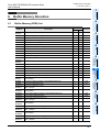
6. Buffer Memory Allocation
37
6.1 Buffer Memory (BFM) List .............................................................................................................. 37
6.2 Cyclic I/O Data Area Compatible with FX0N-32NT-DP [BFM #0 to BFM #19] ............................... 38
6.3 Data Exchange Status Register [BFM #20] ................................................................................... 39
6.4 Swap Byte Order [BFM #21 Bit0 and Bit1]..................................................................................... 39
6.5 Cyclic Input Data Length [BFM #22] .............................................................................................. 39
6.6 Cyclic Output Data Length [BFM #23]............................................................................................ 39
6.7 Transmission Speed [BFM #24]..................................................................................................... 40
6.8 DP Communication Status Register [BFM #25] ............................................................................. 40
6.9 PROFIBUS Module ID [BFM #26].................................................................................................. 41
6.10 Slave Address [BFM #27] ............................................................................................................ 41
6.11 User Diagnostics [BFM #28] ........................................................................................................ 41
6.12 Error Status Register [BFM #29 Bit0 to Bit13].............................................................................. 42
6.13 Module ID Code [BFM #30].......................................................................................................... 42
6.14 Master Address [BFM #33] .......................................................................................................... 42
6.15 Allocated Group ID Number [BFM #34] ....................................................................................... 43
6.16 DP-V1 Communication Parameter [BFM #35] ............................................................................. 43
6.17 Start/Stop DP Communication [BFM #36 Bit0] ............................................................................ 44
6.18 Consistency Handling Error Flags [BFM #37] .............................................................................. 44
6.19 Setting Error Flag [BFM #38] ....................................................................................................... 45
6.20 Cyclic Input Data Consistency Activate/Deactivate Flag [BFM #98 Bit0]..................................... 46
6.21 Cyclic Input Data Send Flag [BFM #99 Bit0]................................................................................ 46
6.22 Cyclic Input Data Send Area [BFM #100 to #171] ....................................................................... 46
6.23 Cyclic Output Data Consistency Activate/Deactivate Flag [BFM #298 Bit0] ................................ 46
6.24 Cyclic Output Data Read Flag [BFM #299 Bit0]........................................................................... 46
6.25 Cyclic Output Data Receive Area [BFM #300 to #371] ................................................................ 46
6.26 Acyclic Input Data Send Flag (Class1) [BFM #499 Bit0].............................................................. 47
6.27 Acyclic Input Data Send Area (Class1) [BFM #500 to #572] ....................................................... 47
6.28 Acyclic Output Data Read Flag (Class1) [BFM #699 Bit0]........................................................... 47
6.29 Acyclic Output Data Receive Area (Class1) [BFM #700 to #772] ................................................ 47
6.30 Acyclic Input Data Send Flag (Class2) [BFM #899 Bit0].............................................................. 48
6.31 Acyclic Input Data Send Area (Class2) [BFM #900 to #972] ....................................................... 48
6.32 Acyclic Output Data Read Flag (Class2) [BFM #1099 Bit0]......................................................... 48
6.33 Acyclic Output Data Receive Area (Class2) [BFM #1100 to #1172] ............................................ 48
6.34 Reset Extended Diagnostic/Alarm Data Area Flag [BFM #1298]................................................. 49
6.35 Alarm/Status Switch [BFM #1299 Bit0] ........................................................................................ 49
6.36 Diagnostic/Alarm Immediate Send Flag [BFM #1300 Bit0] .......................................................... 49
6.37 Diagnostic/Alarm (Status) Data Area ........................................................................................... 50
6.37.1 Master Address [BFM #1301]....................................................................................................... 50
6.37.2 ID Number [BFM #1302]............................................................................................................... 50
6.37.3 Block Length [BFM # 1303] .......................................................................................................... 50
6.37.4 Alarm/Status Type [BFM #1304] .................................................................................................. 50
6.37.5 Slot Number [BFM #1305] ............................................................................................................ 50
6.37.6 Specifier [BFM #1306] .................................................................................................................. 50
6.37.7 Extended Alarm Data [BFM #1307].............................................................................................. 50
6.37.8 Extended Alarm Data [BFM #1308].............................................................................................. 51
6.37.9 Extended Diagnostic/Alarm(Status) Data Area [BFM #1309 to #1322]........................................ 51
7. Parameter Setting and Network Configuration [GX Configurator-DP]
53
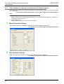
7.1 Slave Parameter Settings .............................................................................................................. 54
7.1.1 Slave Properties ............................................................................................................................. 54
7.1.2 Extended User Parameters ............................................................................................................ 54
7.1.3 Slave Modules ................................................................................................................................ 55
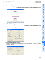
7.2 Network Configuration.................................................................................................................... 55
4
FX3U-32DP PROFIBUS-DP Interface Block
User’s Manual
8. Example Program
57
8.1 Example Program .......................................................................................................................... 57
8.1.1 System Configuration ..................................................................................................................... 57
8.1.2 Contents of Operation .................................................................................................................... 57
8.1.3 Setting Network Configuration and Parameter for Example Program ............................................ 58
8.1.4 Example Program for Cyclic Communication using GX Developer................................................ 61
8.1.5 Example Program for Cyclic Communication using GX IEC Developer (Ver. 7.00 or later)........... 62
8.1.6 Example Program for Acyclic Communication using GX Developer .............................................. 63
8.1.7 Example Program for Acyclic Communication using GX IEC Developer (Ver. 7.00 or later) ......... 64
9. Diagnostics
65
9.1 Check LEDs ................................................................................................................................... 66
9.2 Checking Errors ............................................................................................................................. 67
Warranty................................................................................................................................... 69
Revised History ....................................................................................................................... 70
5
FX3U-32DP PROFIBUS-DP Interface Block
User’s Manual
MEMO
6
FX3U-32DP PROFIBUS-DP Interface Block
User’s Manual
Applicable Standards
Applicable Standards
Compliance with EC Directive (CE Marking)
This note does not guarantee that an entire mechanical module produced in accordance with the contents of
this note will comply with the following standards.
Compliance to EMC and LVD directives for the entire mechanical module should be checked by the user /
manufacturer. For more details please contact your local Mitsubishi Electric sales site.
1. Requirement for Compliance with EMC Directive
The following products have shown compliance through direct testing (of the identified standards below) and
design analysis (through the creation of a technical construction file) to the European Directive for
Electromagnetic Compatibility (89/336/EEC) when used as directed by the appropriate documentation.
Type:
Programmable Controller (Open Type Equipment)
Models: MELSEC FX3U series products, identified here, manufactured from
March 1st, 2007.
FX3U-32DP: PROFIBUS-DP Interface Block for FX3U Series Main Processing
Units.
Standard
EN61131-2:2003
Remark
Programmable controllers
- Equipment requirements
and tests
Compliance with all relevant aspects of the standard.
• Radiated Emissions
• Mains Terminal Voltage Emissions
• RF immunity
• Fast Transients
• ESD
• Conducted
• Surge
• Power magnetic fields
Caution for Compliance with EC Directive
1) Caution for wiring
For noise prevention please attach at least 50 mm (1.97") of the twisted-pair cable along the grounding
plate to which the ground terminal is connected.
→ For wiring details, refer to Section 4.2
2) Installation in Enclosure
→ For details on Enclosure installation, refer to FX3U User’s Manual - Hardware Edition.
Certification of UL, cUL Standards
The following product has UL and cUL certification.
UL, cUL File Number:
Models:
E95239
FX3U-32DP: PROFIBUS-DP Interface Block for FX3U Series Main Processing Units.
7
FX3U-32DP PROFIBUS-DP Interface Block
User’s Manual
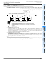
Location and Usage of Manual
Location and Usage of Manual
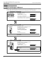
The FX3U-32DP PROFIBUS-DP Interface Block is a DP-Slave for the PROFIBUS-DP network. By connecting
the FX3U-32DP, the FX3U Series PLC can both read and write data from and to a DP-Master.
PLC
FX3U Series PLC
For installation and wiring
- Hardware Manual
(Manual is supplied with product.)
Supplied Manual
- User's Manual - Hardware Edition
Additional Manual
For basic/applied instructions and PLC devices
- Programming Manual - Basic & Applied Instruction Edition
Additional Manual
PROFIBUS-DP Master
If necessary, obtain the following manuals for your network.
FX3U-64DP-M
The installation manual is supplied with the product.
For details, refer to the user's manual.
For installation and wiring
- FX3U-64DP-M Installation Manual
(Manual is supplied with product.)
Supplied Manual
For details
- FX3U-64DP-M User's Manual
Additional Manual
For other master modules Obtain the manual of another PROFIBUS-DP master module to fulfill its requirements
for your network.
PROFIBUS-DP Slave
FX3U-32DP
The hardware manual is supplied with the product.
For details, refer to the user's manual.
For installation and wiring
- Installation Manual
(Manual is supplied with product.)
Supplied Manual
For details
- User's Manual
This manual
8
Additional Manual
This manual details wiring, installation, specification and BFM allocation, etc.
FX3U-32DP PROFIBUS-DP Interface Block
User’s Manual
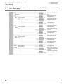
Associated Manuals
Associated Manuals
For a detailed explanation of the FX3U-32DP, refer to this manual.
For hardware information and instructions on the PLC main unit, other special function units/blocks, etc., refer
to the appropriate manuals.
For acquiring required manuals, contact the distributor from where your product was purchased.
~ Indispensable manual
{ Manual that may be indispensable depending on the purpose of use
U Abbreviated document
Manual Name
Manual
Number
Description
Model
Code
Manual for the Main Module
FX3U Series PLCs Main Unit
U
Supplied
Manual
FX3U Series
Hardware Manual
JY997D18801
Describes FX3U Series PLC specification for
I/O, wiring and installation extracted from the
−
FX3U User’s Manual - Hardware Edition.
For details, refer to FX3U Series User’s
Manual - Hardware Edition.
Describes FX3U Series PLC specification
details for I/O, wiring, installation and 09R516
maintenance.
FX3U Series
Additional
User’s Manual
JY997D16501
Manual
- Hardware Edition
Programming for FX3U/FX3UC Series
FX3U / FX3UC Series
Additional Programming Manual
Describes PLC programming for basic/
JY997D16601
09R517
~
Manual - Basic & Applied
applied instructions and devices.
Instruction Edition
Manual for the PROFIBUS-DP Master Block, Interface Block
PROFIBUS-DP Master Block
Describes the FX3U-64DP-M PROFIBUSDP Master Block specification for wiring
Supplied FX3U-64DP-M
and installation extracted from the FX3U−
JY997D19901
U
Manual Installation Manual
64DP-M User’s Manual.
For details, refer to FX3U-64DP-M User’s
Manual.
Describes the FX3U-64DP-M PROFIBUSAdditional FX3U-64DP-M
DP Master Block specification details for
−
JY997D19201
~
Manual User’s Manual
wiring, installation and allocation BFM’s,
etc.
PROFIBUS-DP Interface Block
Describes the FX3U-32DP PROFIBUS-DP
Interface Block specification for wiring and
Supplied FX3U-32DP
installation extracted from the FX3U-32DP
−
JY997D24901
U
Manual Installation Manual
User’s Manual.
For details, refer to FX3U-32DP User’s
Manual.
Describes the FX3U-32DP PROFIBUS-DP
Additional FX3U-32DP
Interface Block specification details for
−
JY997D25201
~
Manual User’s Manual
wiring, installation and allocation BFM’s,
etc.
Describes the FX0N-32NT-DP PROFIBUSSupplied FX0N-32NT-DP
DP Interface Unit specification details for
−
JY992D61401
{
Manual User’s Manual
wiring, installation and allocation BFM’s,
etc.
~
9
FX3U-32DP PROFIBUS-DP Interface Block
User’s Manual
Associated Manuals
~ Indispensable manual
{ Manual that may be indispensable depending on the purpose of use
U Abbreviated document
Manual Name
Manual
Number
Description
Model
Code
PROFIBUS-DP Interface Block
U
Supplied
Manual
FX2N-32DP-IF
Hardware Manual
{
Additional FX2N-32DP-IF
Manual User’s Manual
Configuration Software
GX Cofigurator-DP
Configuration System for
~
Open Networks Software
Manual
10
JY992D77101
JY992D79401
−
Describes the FX2N-32DP-IF PROFIBUSDP Interface Unit specification for wiring
and installation extracted from the FX2N32DP-IF User’s Manual.
For details, refer to FX2N-32DP-IF User’s
Manual.
Describes the FX2N-32DP-IF PROFIBUSDP Interface Unit specification details for
wiring, installation and allocation BFM’s,
etc.
Describes the operation details for the GX
Configurator-DP Configuration System for
Networks Software.
−
−
−
FX3U-32DP PROFIBUS-DP Interface Block
User’s Manual
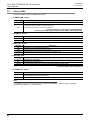
Generic Terms and Abbreviations
Generic Terms and Abbreviations
Generic Name and
Abbreviation
Description
PLCs
FX3U Series
Main unit
Generic name of the FX3U Series
Abbreviated name of the FX3U Series PLC main unit
FX2N Series
Generic name of the FX2N Series
FX0N Series
Generic name of the FX0N Series
Expansion board
Generic name of the FX3U Series expansion board
Special adapter
Generic name of the FX3U Series special adapter
Special function units/block
Generic name of the FX0N/FX2N Series FX3UC Series special function block, and
FX2N Series special function unit
Extension unit/block
Generic name of I/O Extension block and powered extension unit
I/O Extension block
Generic name of FX2N Series extension block
Powered extension unit
Generic name of FX2N Series powered extension unit
PROFIBUS-DP Network
PROFIBUS-DP network
Abbreviated name of the PROFIBUS-DP network
DP-Master
Generic name of the PROFIBUS-DP master module (include FX3U-64DP-M)
64DP-M
DP-Slave
Abbreviated name of FX3U-64DP-M PROFIBUS-DP master block
Generic name of the PROFIBUS-DP slave module
32DP-IF
Abbreviated name of FX2N-32DP-IF PROFIBUS-DP interface block
32NT-DP
Abbreviated name of FX0N-32NT-DP PROFIBUS-DP interface block
GX Configurator-DP
Generic name of configuration system for open networks software Version
7.00A or later.
Programming Tools
Programming tool
Generic name of the programming software and handy programming panel
Programming software
Generic name of the following programming software
GX Developer, FX-PCS/WIN(-E)
GX Developer
Generic name of programming software packages SW
D5C-GPPW-J and
SW
D5C-GPPW-E
GX IEC Developer
Generic name of programming software, GX IEC Developer Ver.7.00 or later
FX-PCS/WIN(-E)
Generic name of programming software packages FX-PCS/WIN and FX-PCS/WIN-E
Handy programming panel Generic name of the following models
(HPP)
FX-20P(-E), FX-10P(-E)
RS-232/RS-422
conversion interface
Generic name of the following models
FX-232AW, FX-232AWC, FX-232AWC-H
USB/RS-422
conversion interface
Abbreviated name of the FX-USB-AW USB/RS-422 Conversion Interface
Manuals
Programming Manual
Abbreviated name of FX3U / FX3UC Series Programming Manual - Basic & Applied
Instruction Edition
FX3U PLC Hardware Edition
Abbreviated name of FX3U Series User's Manual - Hardware Edition
Analog Control Edition
Abbreviated name of FX3U / FX3UC Series User's Manual - Analog Control Edition
Positioning Control Edition
Abbreviated name of FX3U / FX3UC Series User's Manual - Positioning Control Edition
Data Communication Edition Abbreviated name of FX Series User's Manual - Data Communication Edition
GX Configurator-DP
Software Manual
Abbreviated name of GX Cofigurator-DP Configuration System for Open Networks
Software Manual
11
FX3U-32DP PROFIBUS-DP Interface Block
User’s Manual
Reading of the Manual
Reading of the Manual
Shows the manual title.
This area shows the
manual title for the page
currently opened.
Shows the title of the chapter and the title
of the section.
This area shows the title of the chapter and the
title of the section for the page currently opened.
Indexes the chapter number.
The right side of each page
indexes the chapter number
for the page currently opened.
Shows the reference.
The mark of "
" is
expressing the reference
destination and the
reference manual.
The page above is an example. It may differ from the actual page.
12
FX3U-32DP PROFIBUS-DP Interface Block
User’s Manual
1 Introduction
1.1 Product Outline and Features
1
Introduction
2
Product Outline and Features
The FX3U-32DP PROFIBUS-DP Interface Block (hereinafter called 32DP) enables users to integrate the
MELSEC FX3U PLC in any existing PROFIBUS-DP network (DP-V0/DP-V1) as a DP-Slave. The 32DP links
the FX3U PLC with PROFIBUS-DP decentralized control tasks. The module connects the PLC system to the
DP-Master in the PROFIBUS-DP network for efficient and easy data exchange.
The 32DP Interface Module enables the FX3U PLC to fit into an existing PROFIBUS-DP Network as a DPSlave, while reducing the time and cost for users to build up a new network system.
→ For the PROFIBUS-DP Network configuration, refer to Subsection 1.3.1
3
Installation
1. Easy Connectivity to an existing PROFIBUS-DP Network
Specifications
1.1
Introduction
1.
4
2. Enhanced Data Exchange
Wiring
The 32DP has enhanced the data exchange functionality in the following communication formats.
→ For details, refer to Chapter 5 and 6
• Cyclic Input/Output Data Communication - a maximum of 144 Bytes
• Acyclic Input/Output Data Communication - a maximum of 140 Bytes
5
• User-Diagnostic Messages
3. Global Control
The 32DP supports SYNC / UNSYNC / FREEZE / UNFREEZE global controls.
→ For details, refer to Chapter 5
Mode,
Data Comms.,
Global Control
• Alarm(Status) Messages
6
4. Flexible and Easy Network Setting
5. Various Transmission Speed Options
7
Setting
Parameters and
Configuration
The 32DP supports the communication speeds, 9.6k, 19.2k, 45.45k, 93.75k, 187.5k, 500k, 1.5M, 3M, 6M and
12Mbps to fit into various kinds of networks. To connect the 32DP to a PROFIBUS-DP Network, use the
standard 9-pin D-SUB connector and shielded twisted-pair PROFIBUS cable complying with EN50170.
→ For wiring, refer to Chapter 4
→ For the transmission speed parameter, refer to Section 2.3 and 6.7
Allocation of
Buffer Memories
(BFMs)
The 32DP enables a flexible and smooth integration with components on a new/existing PROFIBUS-DP
Network. The FX3U-32DP PROFIBUS Interface Block is fully applicable for the user-specific PROFIBUS-DP
Network.
→ For details, refer to Chapter 7 and 8
8
When this manual references INPUT/OUTPUT for communication data on the PROFIBUS-DP network, it
refers to data from the DP-Master's point of view. Therefore, CYCLIC INPUT DATA means THE CYCLIC
DATA STREAMING FROM DP-SLAVE TO DP-MASTER. On the other hand, ACYCLIC OUTPUT DATA, for
example, means THE ACYCLIC DATA STREAMING FROM DP-MASTER TO DP-SLAVE.
Example
Program
Note : INPUT/OUTPUT to where?
9
Diagnostics
13
FX3U-32DP PROFIBUS-DP Interface Block
User’s Manual
1 Introduction
1.2 External Dimensions
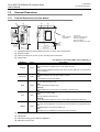
1.2
External Dimensions
1.2.1
External Dimensions and Part Names
[3]
[5]
[4]
[6]
32
90(3.55")
80(3.15")
[2]
[7]
[1]
Unit:
Mass (Weight):
Accessory:
[8]
2-φ4.5
4(0.16")
87(3.43")
89(3.51")
43(1.7")
mm(inches)
Approx. 0.2kg (0.44 lbs)
GSD file (CD-ROM)
Dust Proof Sheet
Special Unit/Block No. Label
9(0.36")
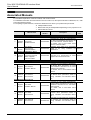
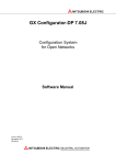
[1] PROFIBUS-DP port (9-pin D-SUB Connector: #4-40unc inch screw thread)
[2] Extension cable
[3] Direct mounting hole: 2-φ4.5 (0.18"), mounting screw: M4 screw
[4] Status LEDs
LED Name
POWER
FROM/TO
RUN
DIA
TOKEN
→ For details on the status LEDs, refer to Section 9.1
Color
Description
Green
ON :
The connected PLC supplies power to the 32DP correctly
OFF :
Power is being supplied incorrectly from the PLC to the 32DP due to an unsecured
cable connection
Green
ON:
Constant FROM/TO access within 200ms intervals
OFF :
No FROM/TO access within 200ms
Green
ON :
In cyclic data exchange mode
OFF :
Not in cyclic data exchange mode
Flashing :
The DP-Master is in clear mode or the 32DP is in fail-safe mode
Red
Green
ON :
Hardware error in the 32DP
OFF:
Normal Operation without errors
Flashing :
A user-diagnostic message or a DP-V1 Alarm/Status message is left unread
ON:
The 32DP has established a connection with the DP-Master at an appropriate baud
rate
A Class2 Master can access the 32DP now
OFF:
The 32DP has not established a connection at any baud rate
[5] Extension port under the top cover
[6] Name plate
[7] DIN rail mounting groove (DIN rail: DIN46277)
[8] DIN rail mounting hook
14
FX3U-32DP PROFIBUS-DP Interface Block
User’s Manual
1.3 Network Configuration
1
PROFIBUS-DP Connector Pin Assignment
Introduction
1.2.2
1 Introduction
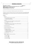
The PROFIBUS-DP connector is a 9-pin D-SUB type. with the following pin assignment.
Description
Receive/Transmit-Data-P
RTS
Ready to send
5
DGND
Data Ground
6
VP
Voltage-Plus
8
RXD/TXD-N
Receive/Transmit-Data-N
NC
Not assigned
1
6
7
8
4
9
RXD/TXD-P
4
4
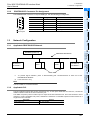
Network Configuration
1.3.1
Applicable PROFIBUS-DP Network
Wiring
1.3
5
DP-Master (Class 1/2)
PROFIBUS-DP Network
*2
PLC
PLC
6
DP-Slave or
DP-Master*1
Allocation of
Buffer Memories
(BFMs)
*2
Mode,
Data Comms.,
Global Control
DP-Slave or
DP-Master*1
3
Installation
Assigned
Not assigned
1, 2, 7, 9
2
Specifications
3
3
Signal Name
2
5
Pin No.
7
FX3U-32DP
To prevent signal reflection, place a self-terminating DP connector/device at each end of the
PROFIBUS-DP Network.
*2.
FX3U series PLC only.
Note
8
The FX3U-32DP is not self-terminated.
Example
Program
1.3.2
Applicable PLC
PLC Type
Version
Ver. 2.21 or later
15
9
Diagnostics
The FX3U-32DP functions with an FX3U series PLC only. To set up the 32DP with an FX3U PLC, connect the
32DP’s extension cable to the PLC’s extension port.
The 32DP occupies 8 points on either input or output of the PLC extension bus. The FX3U series PLC has a
maximum of 384 controllable I/O points, whereas the maximum connectable special function blocks for a
single FX3U PLC is 8 units.
FX3U series PLC
Setting
Parameters and
Configuration
*1.
FX3U-32DP PROFIBUS-DP Interface Block
User’s Manual
1.4
1 Introduction
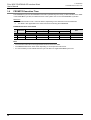
1.4 FROM/TO Execution Time
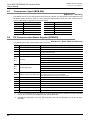
FROM/TO Execution Time
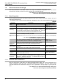
The PROFIBUS cycle time and FROM/TO instruction operates asynchronously. If data is written to the 32DP
in the PROFIBUS cycle time, this data will move to the system area on the next PROFIBUS cycle time.
Reference
The FROM/TO Execution Time*1 varies as follows, depending on the data amount to be transferred.
*1.
This table is also applicable to the other instructions accessing the 32DP BFMs.
FROM/TO Execution Time details
Execution time in ON status (µs)
FNC
Instruction
No.
16-bit instruction 32-bit instruction
Execution time in OFF status (µs)
Note
16-bit instruction
32-bit instruction
1.105
BFM#100 to #171
1.105
BFM#300 to #371
FX3U-32DP
78
FROM
15 + 250n
15 + 320n
0.585
79
TO
15 + 280n
15 + 415n
0.585
n: The number of transferred data
Note
• The execution times above are approximate values for the FX3U-32DP.
• The FROM/TO Execution Time varies depending on each special function block.
• It is not necessary to check all DP-Slaves' cyclic I/O data in a single PROFIBUS Cycle Time.
16
FX3U-32DP PROFIBUS-DP Interface Block
User’s Manual
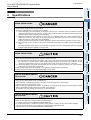
1.5 System Start-up Procedure
1
System Start-up Procedure
Introduction
1.5
1 Introduction
FX3U-32DP
2
Refer to Chapter 1
Specifications
Outline of system:
• Applicable PLC
• Applicable PROFIBUS configuration tool
Outline
Refer to Chapter 2
3
Specifications:
• Operation environment
• Power supply specifications
• Performance specifications
Installation
Check of specifications
Refer to Chapter 1 and 2
4
System configuration:
Wiring
System configuration
Refer to Chapter 3 and 4
Installation and wiring
Communication setting for 32DP
Configuration setting:
• Create network configuration by configuration
tool
• Set parameter for DP-Master and DP-Slave
Refer to Chapter 7
Test run (communication test)
Configuration/Communication test:
• Change DP-Master to the Data Exchange Mode
• Check communication status (RUN LED)
8
Example
Program
Buffer memory:
• List of buffer memories
• Details of buffer memory
• For buffer memory read/write method,
refer to programming manual
Communication program:
→ For example program, refer to Chapter 8
• Cyclic communication program
• Acyclic communication program
Create program
7
Setting
Parameters and
Configuration
Refer to Chapter 5 and 6
6
Allocation of
Buffer Memories
(BFMs)
Turn ON power
Mode,
Data Comms.,
Global Control
Refer to Chapter 7
5
Installation:
• Arrangements
• Mounting
Wiring:
• Applicable cable and connector
• PROFIBUS-DP wiring
• Bus terminator
Refer to Chapter 9
9
Diagnostics
If error occurs, refer to Chapter 9.
17
FX3U-32DP PROFIBUS-DP Interface Block
User’s Manual
1 Introduction
1.5 System Start-up Procedure
MEMO
18
FX3U-32DP PROFIBUS-DP Interface Block
User’s Manual
2 Specifications
1
Introduction
2.
Specifications
2
3
Installation
4
Wiring
• Make sure to have the following safety circuits outside of the PLC to ensure safe system operation even during
external power supply problems or PLC failure.
Otherwise, malfunctions may cause serious accidents.
1) Most importantly, have the following: an emergency stop circuit, a protection circuit, an interlock circuit for
opposite movements (such as normal vs. reverse rotation), and an interlock circuit (to prevent damage to the
equipment at the upper and lower positioning limits).
2) Note that when the PLC CPU detects an error, such as a watchdog timer error, during self-diagnosis, all
outputs are turned off. Also, when an error that cannot be detected by the PLC CPU occurs in an input/
output control block, output control may be disabled.
External circuits and mechanisms should be designed to ensure safe machinery operation in such a case.
3) Note that when an error occurs in a relay, triac or transistor output device, the output could be held either on
or off.
For output signals that may lead to serious accidents, external circuits and mechanisms should be designed
to ensure safe machinery operation in such a case.
Specifications
DESIGN PRECAUTIONS
5
6
Allocation of
Buffer Memories
(BFMs)
• Make sure to observe the following precautions in order to prevent any damage to the machinery or accidents
due to abnormal data written to the PLC under the influence of noise:
1) Do not bundle the main circuit line together with or lay it close to the main circuit, high-voltage line, or load
line. Otherwise, noise disturbance and/or surge induction are likely to take place. As a guideline, lay the
control line at least 100mm (3.94") or more away from the main circuit, high-voltage line, or load line.
2) Ground the shield wire or shield of the shielded cable at one point on the PLC. However, do not ground them
at the same point as the high-voltage lines.
• Install module so that excessive force will not be applied to peripheral device connectors.
Failure to do so may result in wire damage/breakage or PLC failure.
Mode,
Data Comms.,
Global Control
DESIGN PRECAUTIONS
7
8
Example
Program
• Do not touch any terminal while the PLC’s power is on.
Doing so may cause electric shock or malfunctions.
• Before cleaning or retightening terminals, externally cut off all phases of the power supply.
Failure to do so may cause electric shock.
• Before modifying or disrupting the program in operation or running the PLC, carefully read through this manual
and the associated manuals and ensure the safety of the operation.
An operation error may damage the machinery or cause accidents.
Setting
Parameters and
Configuration
STARTUP AND MAINTENANCE
PRECAUTIONS
9
Diagnostics
STARTUP AND MAINTENANCE
PRECAUTIONS
• Do not disassemble or modify the unit.
Doing so may cause fire, equipment failures, or malfunctions.
* For repair, contact your local Mitsubishi Electric distributor.
• Do not drop the product or expose the product to strong impacts, as doing so may cause product damage.
• Turn off the power to the PLC before attaching or detaching the peripheral devices.
Failure to do so may cause equipment failures or malfunctions.
19
FX3U-32DP PROFIBUS-DP Interface Block
User’s Manual
2 Specifications
2.1 General Specifications
DISPOSAL PRECAUTIONS
• Please contact a certified electronic waste disposal company for the environmentally safe recycling and disposal
process for your device.
TRANSPORT AND STORAGE
PRECAUTIONS
• The PLC and peripheral devices are precision instrument. During transportation, avoid impacts. After
transportation, verify the operation of the products.
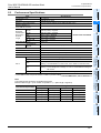
2.1
General Specifications
The FX3U PLC’s general specifications except the following items are applicable to the 32DP specifications.
However, do not perform any dielectric withstand voltage tests or insulation resistance tests on this product.
→ Refer to FX3U PLC Hardware Edition
Item
Withstand voltage
Insulation resistance
2.2
500 V AC for 1 min
Compliant with JEM-1021 between communication
5 MΩ or more by 500 V DC connector frame and ground terminal of PLC main unit
Insulation tester
Power Supply Specifications
Items
Internal Power Supply
20
Specifications
Description
145 mA at 24V DC is supplied from the internal service power in the main unit via
extension cable
FX3U-32DP PROFIBUS-DP Interface Block
User’s Manual
2.3 Performance Specifications
1
Performance Specifications
Item
Introduction
2.3
2 Specifications
Specifications
Bus network
Unit Type
PROFIBUS-DP Slave
Maximum Transmission Data
144 Byte (default: 32Byte Input / 32Byte Output cyclic)
Maximum Number of
FX3U-32DP at one PLC
8 units
9.6k, 19.2k, 45.45k,
1,200 m (3,937') / segment
93.75k
187.5k
1,000 m (3,281') / segment
500k
400 m (1,312') / segment
1.5 M
200 m (656') / segment
3M, 6M, 12M
100 m (328') / segment
PROFIBUS Module ID
Connector
→ Refer to the note below
“F332” hex
PROFIBUS-DP
Network
4
Port for PROFIBUS-DP network (9 pin D-SUB Connector)
Supports SYNC, UNSYNC, FREEZE, and UNFREEZE modes
Terminal Resistor
Not built in.
Number of occupied I/O points
Occupies 8 points on either input or output of PLC extension bus
Applicable PLC
FX3U Series PLC
Wiring
Global Control
5
ON : Constant FROM/TO access within 200ms intervals
RUN
ON : In cyclic data exchange mode
Flashing : The DP-Master is in clear mode, or the 32DP is in fail-safe mode
DIA
ON : Hardware error in the 32DP
Flashing : A User-Diagnostic message or a DP-V1 Alarm/Status message is
left unread
TOKEN
ON : Connected properly with the DP-Master at an appropriate baud rate
*1 The LEDs on the front panel show the 32DP’s operation status.
→ For the LED details, refer to Section 9.1
Note
The following table shows the acceptable bus length.
Maximum Bus Length = (The number of repeaters + 1) × (Bus Length / segment)
7
Setting
Parameters and
Configuration
Transmission Speed (bps)
Maximum Bus Length
No repeater
1 repeater
2 repeaters
6
Allocation of
Buffer Memories
(BFMs)
ON : The connected PLC supplies power to the 32DP correctly
FROM/TO
Mode,
Data Comms.,
Global Control
POWER
LED *1
3
Installation
Supported
Transmission
Speed (bps)
and Bus
Length
2
Specifications
Transmission Type
3 repeaters
1,200 m (3,937')
2,400 m (7,874') 3,600 m (11,811') 4,800 m (15,748')
187.5k
1,000 m (3,281')
2,000 m (6,562')
3,000 (9,843')
4,000 m (13,123')
500k
400 m (1,312')
800 m (2,625')
1,200 m (3,937')
1,600 m (5,249')
1.5 M
200 m (656')
400 m (1,312')
600 m (1,969')
800 m (2,625')
3M, 6M, 12M
100 m (328')
200 m (656')
300 m (984')
400 m (1,312')
8
Example
Program
9.6k, 19.2k, 45.45k, 93.75k
9
Diagnostics
21
FX3U-32DP PROFIBUS-DP Interface Block
User’s Manual
2 Specifications
2.3 Performance Specifications
MEMO
22
FX3U-32DP PROFIBUS-DP Interface Block
User’s Manual
3 Installation
1
Introduction
3.
Installation
2
3
Installation
4
Wiring
• Make sure to have the following safety circuits outside of the PLC to ensure safe system operation even during
external power supply problems or PLC failure.
Otherwise, malfunctions may cause serious accidents.
1) Most importantly, have the following: an emergency stop circuit, a protection circuit, an interlock circuit for
opposite movements (such as normal vs. reverse rotation), and an interlock circuit (to prevent damage to the
equipment at the upper and lower positioning limits).
2) Note that when the PLC CPU detects an error, such as a watchdog timer error, during self-diagnosis, all
outputs are turned off. Also, when an error that cannot be detected by the PLC CPU occurs in an input/
output control block, output control may be disabled.
External circuits and mechanisms should be designed to ensure safe machinery operation in such a case.
3) Note that when an error occurs in a relay, triac or transistor output device, the output could be held either on or off.
For output signals that may lead to serious accidents, external circuits and mechanisms should be designed
to ensure safe machinery operation in such a case.
Specifications
DESIGN PRECAUTIONS
5
DESIGN PRECAUTIONS
Mode,
Data Comms.,
Global Control
6
Allocation of
Buffer Memories
(BFMs)
• Make sure to observe the following precautions in order to prevent any damage to the machinery or accidents
due to abnormal data written to the PLC under the influence of noise:
1) Do not bundle the main circuit line together with or lay it close to the main circuit, high-voltage line, or load
line. Otherwise, noise disturbance and/or surge induction are likely to take place. As a guideline, lay the
control line at least 100mm (3.94") or more away from the main circuit, high-voltage line, or load line.
2) Ground the shield wire or shield of the shielded cable at one point on the PLC. However, do not ground them
at the same point as the high-voltage lines.
• Install module so that excessive force will not be applied to peripheral device connectors.
Failure to do so may result in wire damage/breakage or PLC failure.
7
Setting
Parameters and
Configuration
INSTALLATION PRECAUTIONS
• Make sure to cut off all phases of the power supply externally before attempting installation or wiring work.
Failure to do so may cause electric shock.
8
23
9
Diagnostics
• Use the product within the generic environment specifications described in the PLC main unit manual (Hardware Edition).
Never use the product in areas with dust, oily smoke, conductive dusts, corrosive gas (salt air, Cl2, H2S, SO2, or
NO2), flammable gas, vibration or impacts, or exposed to high temperature, condensation, or wind and rain.
If the product is used in such conditions, electric shock, fire, malfunction, deterioration or damage may occur.
• Install the product securely using a DIN rail or mounting screws.
• Install the product on a flat surface.
If the mounting surface is rough, undue force will be applied to the PC board, thereby causing nonconformities.
• When drilling screw holes or wiring, make sure cutting or wire debris does not enter the ventilation slits.
Failure to do so may cause fire, equipment failures or malfunctions.
• Be sure to remove the dust proof sheet from the PLC's ventilation port when the installation work is completed.
Failure to do so may cause fires, equipment failures, and malfunctions.
• Connect the extension and communication cables securely to their designated connectors.
Unsecured connection may cause malfunctions.
• Do not touch the conductive parts of the product directly to avoid failure or malfunction.
Example
Program
INSTALLATION PRECAUTIONS
FX3U-32DP PROFIBUS-DP Interface Block
User’s Manual
3.1
3 Installation
3.1 Installation Arrangements
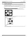
Installation Arrangements
The 32DP is connected to the extension port of an FX3U series PLC or extension unit/block (including special
function unit/block) on the right side.
Since additional extension devices can be added on both the left and right-hand sides of the PLC, keep an
appropriate amount of space on both sides of the PLC when planning to add extension devices in the future.
For further details on installation arrangements, refer to the following manual.
→ FX3U PLC Hardware Edition
Note
• Keep a space of 50 mm (1.97") or more between the 32DP and the other devices and cabinet.
Install the unit as far from high-voltage lines, high-voltage devices and power equipment as possible.
A
FX3U Series
main unit
A
FX3U-32DP
A
A
A ≥ 50mm (1.97")
• To prevent the product’s temperature from rising, do not install the PLC on a floor, ceiling, or in the vertical
direction. Install it horizontally on a wall as shown below.
• Take care to position the 32DP and other peripheral devices for their extension ports and cables to be as
close to each other as possible.
24
FX3U-32DP PROFIBUS-DP Interface Block
User’s Manual
3.2 Mounting
1
Mounting
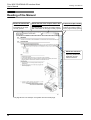
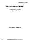
The 32DP can be mounted on a DIN rail (DIN46227) or mounted directly to the mounting surface with screws.
Direct Mounting
2
39
(1.54")
3
Installation
90 (3.55")
4
(0.16")
Specifications
The 32DP can be directly mounted with M4 screws.
The 32DP mounting hole pitches are shown below.
→ For the connecting procedure to the extension port, refer to FX3U PLC Hardware Edition
80 (3.15")
3.2.1
Introduction
3.2
3 Installation
4
Wiring
Note
• Mounting screw: M4 screw.
• An interval space between each unit of 1 to 2 mm (0.04" to 0.08") is necessary.
• When connecting the 32DP to an extension unit/block (or special function unit/block), first mount the
extension unit/block (or special function unit/block) to the right side of the PLC.
5
1) Drill screw holes on the mounting surface according to the
diagram above.
Mode,
Data Comms.,
Global Control
Direct Mounting
2) Align the 32DP (right fig. A) with the holes and tighten with
M4 screws (right fig. B).
6
Allocation of
Buffer Memories
(BFMs)
FX
3U
-48
M
IN 0
10
1
11
2
12
3
13
4
14
5
15
6
16
7
17
20
21
T
0
10
1
7
22
23
24
25
26
PO
27
PO
WER
WER
RURU
N N
3
11
4
12
BA BA
5
TT TT
13
6
14
ERER
7
15
RORO
20
16
R R
21
17
22
23
24
25
Setting
Parameters and
Configuration
OU
2
26
27
B
8
Example
Program
A
B
3) Connect the 32DP’s extension cable (right fig. C) to the
extension device connector of the main unit.
→ For extension cable connection procedures,
refer to FX3U PLC Hardware Edition
9
Diagnostics
25
FX3U-32DP PROFIBUS-DP Interface Block
User’s Manual
3.2.2
3 Installation
3.2 Mounting
DIN Rail Mounting
The 32DP can be mounted on a DIN rail (DIN46227, 35mm width).
→ For detail, refer to FX3U PLC Hardware Edition
Note
• An interval space between each unit of 1 to 2 mm (0.04" to 0.08") is necessary.
• When connecting the 32DP to an extension unit/block (or special function unit/block), first mount the
extension unit/block (or special function unit/block) to the right side of the PLC.
DIN Rail Mounting
1) Fit the upper edge of the DIN rail mounting groove (right fig. A) onto the DIN
rail.
1)
2) Push the product onto the DIN rail.
A
2)
3) Connect the 32DP’s extension cable (right fig. B) to the
extension device connector of the main unit.
→ For extension cable connection procedures,
refer to FX3U PLC Hardware Edition
Removing from DIN Rail
1) Disconnect the PROFIBUS-DP communication cable and extension cables.
2) Insert the tip of a flathead screwdriver into the hole of the DIN rail
mounting hook (right fig. A).
3) Move the flathead screwdriver as shown in the figure to the right, pull
out the DIN rail mounting hook (right fig. A).
4) Remove the product from the DIN rail (right fig. B).
B
4)
A
3)
2)
26
FX3U-32DP PROFIBUS-DP Interface Block
User’s Manual
4 Wiring
4.1 Applicable Cable and Connector
1
Introduction
4.
Wiring
2
• Cut off all phases of the power supply externally before installation or wiring work in order to avoid damage to the
product or electric shock.
• When drilling screw holes or wiring, make sure cutting or wire debris does not enter the ventilation slits.
Failure to do so may cause fire, equipment failures or malfunctions.
6
Allocation of
Buffer Memories
(BFMs)
Applicable Cable and Connector
7
Setting
Parameters and
Configuration
The following table shows the applicable cable and connector for a PROFIBUS-DP network.
Description
PROFIBUS-DP network cable Shielded twisted-pair PROFIBUS cable complying with EN50170
Connector
5
Mode,
Data Comms.,
Global Control
WIRING PRECAUTIONS
Item
4
Wiring
WIRING PRECAUTIONS
4.1
3
Installation
• Make sure to observe the following precautions in order to prevent any damage to the machinery or accidents
due to abnormal data written to the PLC under the influence of noise:
1) Do not bundle the main circuit line together with or lay it close to the main circuit, high-voltage line, or load
line. Otherwise, noise disturbance and/or surge induction are likely to take place. As a guideline, lay the
control line at least 100mm (3.94") or more away from the main circuit, high-voltage line, or load line.
2) Ground the shield wire or shield of the shielded cable at one point on the PLC. However, do not ground them
at the same point as the high-voltage lines.
• Install module so that excessive force will not be applied to peripheral device connectors.
Failure to do so may result in wire damage/breakage or PLC failure.
Specifications
DESIGN PRECAUTIONS
Applicable only to PROFIBUS connector
(9-pin D-SUB Connector: #4-40unc inch screw thread)
8
Example
Program
→ For PROFIBUS connectors, refer to the respective PROFIBUS
connector manual
9
Diagnostics
27
FX3U-32DP PROFIBUS-DP Interface Block
User’s Manual
4.2
4 Wiring
4.2 PROFIBUS-DP Wiring
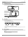
PROFIBUS-DP Wiring
To connect the 32DP to a PROFIBUS-DP network, use the PROFIBUS connector and shielded twisted-pair
PROFIBUS cable complying with EN50170.
Shielded twisted-pair
PROFIBUS cable to
PROFIBUS-DP
network
PROFIBUS connector
FX3U-32DP
PROFIBUS-DP Interface Block
For noise prevention, please attach
at least 50mm (1.97") of the
twisted-pair PROFIBUS cable
along the grounding plate to which
the ground terminal is connected.
FX3U Series PLC
FX3U-32DP
PROFIBUS-DP
Interface Block
Shielded twisted-pair
PROFIBUS cable
complying with EN50170
to PROFIBUS-DP network
Grounding plate
Grounding resistance of 100 Ω or less (Class D)
4.3
Grounding
Ground the cable as stated below.
• Use a grounding resistor of 100Ω or less.
• Ground the cables indepently for best results.
When independent grounding is not used, use "shared grounding" as follows.
PLC
Other
equipment
Independent grounding
Best condition
PLC
Other
equipment
Shared grounding
Good condition
PLC
Other
equipment
Common grounding
Not allowed
• The grounding wire size should be AWG 14 (2 mm2) or larger.
• The grounding point should be as close to the PLC as possible, and all grounding wire should be as short
as possible.
4.4
Bus Terminator
To avoid signal reflections, connect a self-terminating DP-Connector/Device at each end of the PROFIBUSDP Network.
Note
The FX3U-32DP is not sef-terminated.
28
FX3U-32DP PROFIBUS-DP Interface Block
User’s Manual
5 Communication Outline on PROFIBUS-DP Network
5.1 Cyclic Input/Output Data Communication
1
Communication Outline on PROFIBUS-DP Network
2
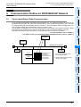
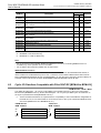
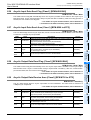
Cyclic Input/Output Data Communication
3
Installation
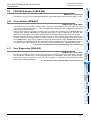
Cyclic I/O Data Communication exchanges data periodically (e.g. I/O, analog input value, etc.) between the
DP-Master and the 32DP. The 32DP can exchange data in cyclic I/O data communication (not in the Data
Consistency Mode) with the DP-Master when the I/O data <= 16 bit, whereas the 32DP exchanges data in the
Data Consistency Mode with the DP-Master when the I/O data > 16 bit.
The DP-Master configuration tool (e.g. GX Configurator-DP) automatically sets the Data Consistency Mode
ON, depending on the data size to exchange, while users can also set this mode ON/OFF manually.
BFM #98 and #298 show the mode status. The allowable data size is a maximum of 144Byte.
→ For flag allocations, refer to Chapter 6
→ For details on the Cyclic Input/Output Data Send/Receive Areas, refer to Chapter 6
Specifications
5.1
Introduction
5.
4
DP Master
Wiring
DP Slave
PROFIBUS-DP Network
Mode,
Data Comms.,
Global Control
DP Slave
5
DP Slave
Read*2
*1 TO or WBFM applied instructions,
directly specifying BFMs
*2 FROM or RBFM applied instructions,
directly specifying BFMs
Buffer Memory
FX3U PLC Main Unit
FX3U-32DP
6
Allocation of
Buffer Memories
(BFMs)
Input-Send Area for
Cyclic Data
Communication
Output-Receive Area
for Cyclic Data
Communication
Write*1
7
Setting
Parameters and
Configuration
8
Example
Program
9
Diagnostics
29
FX3U-32DP PROFIBUS-DP Interface Block
User’s Manual
5.1.1
5 Communication Outline on PROFIBUS-DP Network
5.1 Cyclic Input/Output Data Communication
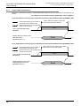
Cyclic Data Consistency
When the Cyclic Data Consistency Activate/Deactivate Flags turn ON, the cyclic data process behaves as
follows:
→ For details on Cyclic Communication related flags, refer to Chapter 6
Cyclic Input Data Consistency (Cyclic Input Data Consistency Activate/Deactivate Flag BFM#98 = ON)
: Set ON automatically by FX3U-32DP if
Input Data can be written by user
Able to write to the 32DP's Cyclic Input
Data Send Area for this duration
: Must be set OFF by user program after
writing of all Input Data
Cyclic Input Data Send Flag
(BFM#99)
Writing data to the Cyclic Input
Data Send Area
(BFM#100 to #171)
ON
Write
Cyclic Output Data Consistency (Cyclic Output Data Consistency Activate/Deactivate Flag BFM#298 = ON)
: Set ON automatically by FX3U-32DP if
Output Data can be read by user
Able to read from the 32DP's Cyclic Output
Data Receive Area for this duration
: Must be set OFF by user program after
reading of Output Data
Cyclic Output Data Read Flag
(BFM#299)
Reading data from the Cyclic
Output Data Receive Area
(BFM#300 to #371)
30
ON
Read
FX3U-32DP PROFIBUS-DP Interface Block
User’s Manual
5.2 Acyclic Input/Output Data Communication
1
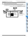
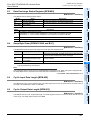
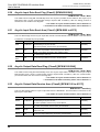
Acyclic Input/Output Data Communication
DP Master
2
Specifications
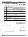
Acyclic I/O data communication is available for changing DP-Slave parameters during cyclic communication.
The allowable data size is a maximum of 140Byte. Cyclic Communication has a higher priority than Acyclic
Communication. Acyclic Communication is always processed in the Data Consistency Mode.
→ For flag allocations, refer to Chapter 6
→ For details on Acyclic Input-Send/Output-Receive Area, refer to Chapter 6
Introduction
5.2
5 Communication Outline on PROFIBUS-DP Network
3
DP Slave
Installation
PROFIBUS-DP Network
DP Slave
DP Slave
Read*2
4
Wiring
Input-Send Area for
Acyclic Data
Communication
Output-Receive Area
for Acyclic Data
Communication
Write*1
*1 TO or WBFM applied instructions,
directly specifying BFMs
*2 FROM or RBFM applied instructions,
directly specifying BFMs
5
Buffer Memory
Mode,
Data Comms.,
Global Control
FX3U PLC Main Unit
FX3U-32DP
6
Allocation of
Buffer Memories
(BFMs)
7
Setting
Parameters and
Configuration
8
Example
Program
9
Diagnostics
31
FX3U-32DP PROFIBUS-DP Interface Block
User’s Manual
5.2.1
5 Communication Outline on PROFIBUS-DP Network
5.2 Acyclic Input/Output Data Communication
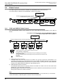
Acyclic Data Consistency
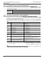
Acyclic Data Communication is always processed in the Data Consistency Mode, regardless of the BFM#98
or BFM#298 settings. The 32DP supports Class 1 and 2 Acyclic Communication.
→ For details on Acyclic Communication related flags, refer to Chapter 6
Acyclic Input Data Communication
: Set ON automatically by FX3U-32DP if
Input Data can be written by user
Able to write to the 32DP's Acyclic Input
Data Send Area for this duration*1
: Must be set OFF by user program
after writing of all Input Data
Class1 Acyclic Input Data Send
Flag (BFM#499)
Writing data to the acyclic Input
Data Send Area (Class1)
(BFM#500 to #572)
ON
Write
Acyclic Output Data Communication
: Set ON automatically by FX3U-32DP if
Output Data can be read by user
Able to read from the 32DP's Acyclic Output
Data Receive Area for this duration*1
: Must be set OFF by user program
after reading of Output Data
Class1 Acyclic Output Data Read
Flag (BFM#699)
Reading data from the Acyclic
Output Data Receive Area (Class1)
(BFM#700 to #772)
*1.
ON
Read
For Class 1: To prevent an "Acyclic Class 1 Response Timeout," the response time must be smaller
than 10 seconds.
For Class 2: The "Acyclic Class 2 Response Timeout" will be set by the Initiate-request
(SendTimeout value) from the DP-Master.
Note : INPUT/OUTPUT to where?
When this manual references INPUT/OUTPUT for communication data on the PROFIBUS-DP network, it
refers to data from the DP-Master's point of view. Therefore, CYCLIC INPUT DATA means THE CYCLIC
DATA STREAMING FROM DP-SLAVE TO DP-MASTER. On the other hand, ACYCLIC OUTPUT DATA, for
example, means THE ACYCLIC DATA STREAMING FROM DP-MASTER TO DP-SLAVE.
32
FX3U-32DP PROFIBUS-DP Interface Block
User’s Manual
5.3 Diagnostic Data Communication
1
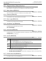
Diagnostic Data Communication
Note
DP Master
3
Installation
If BFM#1299 Bit 0 turns to 1 when BFM#35 Bit0 = 0, BFM#38 Bit13 displays " BFM#1299 Setting Error."
→ For flag allocations, refer to Chapter 6
→ For details on Slave Diagnostic Data, refer to Chapter 6
2
Specifications
The 32DP classifies the diagnostic data into two categories : Alarm Message and Status Message. When the
32DP’s DP-V1 functionality is ON (BFM#35 Bit0 = 1) and the Alarm/Status Switch is OFF (BFM#1299 Bit0 =
0), the 32DP can send a diagnostic message as a high-prioritized Alarm Message. This Alarm Message from
the 32DP needs to be acknowledged by the DP-Master. If this alarm-acknowledging step is not necessary,
the 32DP can send a diagnostic message as a low-prioritized Status Message when users set the Alarm/
Status Switch (BFM#1299 Bit0 = 1).
The content of BFM#1299 Bit0 is mapped to BFM#35 Bit2.
Introduction
5.3
5 Communication Outline on PROFIBUS-DP Network
4
DP Slave
Wiring
PROFIBUS-DP Network
DP Slave
DP Slave
Read*1
Diagnostic/Alarm
(Status) Data Area
Write*2
Buffer Memory
*1 FROM or RBFM applied instructions,
directly specifying BFMs
*2 TO or WBFM applied instructions,
directly specifying BFMs
6
Allocation of
Buffer Memories
(BFMs)
FX3U PLC Main Unit
5
Mode,
Data Comms.,
Global Control
Diagnostic/Alarm
Immediate Send Flag
BFM #1300
FX3U-32DP
The 32DP sends Alarm Message to the DP-Master
The DP-Master acknowledges Alarm Message
7
Diagnostic Data Communication
Diagnostic Data Communication is always processed in the Data Consistency mode, regardless of the
BFM#98 setting.
→ For details on Diagnostic Data related flags, refer to Chapter 6
: Is automatically reset after send of data
Writing data to the
Diagnostic/Alarm Data Area
(BFM#1309 to #1322)
ON
9
Diagnostics
Diagnostic/Alarm immediate
Flag (BFM#1300)
8
Do not write to the
32DP's Diagnostic/
Alarm(Status) Data
Area for this
duration
Example
Program
: Must be set ON by user program
Setting
Parameters and
Configuration
5.3.1
Write
33
FX3U-32DP PROFIBUS-DP Interface Block
User’s Manual
5.4
5 Communication Outline on PROFIBUS-DP Network
5.4 Global Control
Global Control
The 32DP supports SYNC,UNSYNC, FREEZE and UNFREEZE Global Control Services.
The default setting is UNSYNC and UNFREEZE in Global Control Mode.
DP-Master
Example: Sending the Global Control Command
to the DP-Slaves in groups 1 and 2
PROFIBUS-DP Network
Group 1
Group 5
Group 2
Group 8
5.4.1
SYNC and UNSYNC Global Control
The SYNC/UNSYNC Global Control handles the cyclic output data from the DP-Master to the 32DP as
follows:
→ For details on Global Control, refer to the DP-Master’s Manual
→ For Cyclic Output Data, refer to Chapter 6
DP-Master
Example: Sending the SYNC command to DP-Slaves in group 1.
(Group 1)
(Group 2)
DP-Slave 1
...
PROFIBUS-DP Network
(Group 1)
DP-Slave 2
...
(Group 1)
DP-Slave 3
DP-Slave n
...
...
. . . Output image memory: Data is always refreshed by polling.
. . . <During UNSYNC mode(default)>
The data is transferred to the output image memory immediately (normal condition)
<During SYNC mode>
The data is transferred to the output image memory at the SYNC command from the
DP-Master.
. . . SYNC Command
1) SYNC Global Control command
In SYNC mode, the cyclic output data to the 32DP in the group(s) specified by DP-Master is not
immediately transferred to the output image memory of the 32DP. The 32DP holds the cyclic output data
until the next SYNC/UNSYNC Global Control command. When receiving the next SYNC/UNSYNC
command, the 32DP transfers the data to its output image memory.
2) UNSYNC Global Control command
The UNSYNC Global Control command releases the 32DP from SYNC mode and the 32DP starts
updating the cyclic output data continuously.
By specifying groups of DP-Slaves, the DP-Master sends the UNSYNC command arbitrarily to those DPSlave groups, similar to the SYNC command.
Note
When using SYNC Global Control command, the cyclic output data (sent to the DP-Slave) is not refreshed
until the next SYNC or UNSYNC global command is sent to the DP-Slave.
34
FX3U-32DP PROFIBUS-DP Interface Block
User’s Manual
5.4 Global Control
1
FREEZE and UNFREEZE Global Control
The FREEZE/UNFREEZE Global Control handles the cyclic input data communication from the 32DP to the
DP-Master.
→ For datails on Global Control, refer to the DP-Master’s Manual
→ For Cyclic Input Data, refer to Chapter 6
(Group 8)
(Group 3)
...
PROFIBUS-DP Network
(Group 3)
DP-Slave 2
...
3
(Group 3)
DP-Slave 3
Installation
DP-Slave 1
2
Specifications
DP-Master
Example: Sending the FREEZE command to DP-Slaves in
group 3.
Introduction
5.4.2
5 Communication Outline on PROFIBUS-DP Network
DP-Slave n
...
...
4
Wiring
. . . Input image memory: The data is always refreshed by polling.
. . . <During UNFREEZE mode(default)>
The data is transferred to the input image memory immediately (normal condition)
<During FREEZE mode>
The data is transferred to the input image memory at the FREEZE command from the
DP-Master.
. . . FREEZE Command
5
Note
7
Setting
Parameters and
Configuration
When using the FREEZE Global Control command, the cyclic input data (received from the DP-Slave) is not
refreshed until the next FREEZE or UNFREEZE global command to the DP-Slave.
6
Allocation of
Buffer Memories
(BFMs)
2) UNFREEZE Global Control command
An UNFREEZE Global Control command releases the 32DP from FREEZE mode and the 32DP starts
updating the cyclic input data continuously.
By specifying groups of DP-Slaves, the DP-Master sends the UNFREEZE command arbitrarily to those
DP-Slave groups, similar to the FREEZE command.
Mode,
Data Comms.,
Global Control
1) FREEZE Global Control command
In Freeze mode, the cyclic input data from the 32DP in the group specified by DP-Master is not
immediately transferred to its input image memory. The 32DP holds the cyclic input data until the next
FREEZE/UNFREEZE Global Control command. When receiving the next FREEZE/UNFREEZE
command, the 32DP transfers the data to the input image memory.
8
Example
Program
9
Diagnostics
35
FX3U-32DP PROFIBUS-DP Interface Block
User’s Manual
5 Communication Outline on PROFIBUS-DP Network
5.4 Global Control
MEMO
36
FX3U-32DP PROFIBUS-DP Interface Block
User’s Manual
6 Buffer Memory Allocation
6.1 Buffer Memory (BFM) List
1
Buffer Memory Allocation
2
Buffer Memory (BFM) List
BFM No.
Description
BFM Access
Read Write
Reference
Cyclic I/O Data Area Compatible with FX0N-32NT-DP
BFM#20
Data Exchange Status Register
3
−
6.3
BFM#21
Swap Byte Order
3
−
6.4
3
3
6.2
BFM#22
Cyclic Input Data Length
3
−
6.5
BFM#23
Cyclic Output Data Length
3
−
6.6
Transmission Speed
3
−
6.7
DP Communication Status Register
3
3
6.8
6.10
BFM#28
User Diagnostics
3
3
6.11
BFM#29
Error Status Register
3
3
6.12
BFM#30
Module ID Code
3
−
6.13
BFM#31 to
BFM#32
Not Available
−
−
−
BFM#33
Master Address
3
−
6.14
BFM#34
Allocated Group ID Number
3
−
6.15
BFM#35
DP-V1 Communication Parameter
3
−
6.16
BFM#36
Start/Stop DP Communication
3
3
6.17
BFM#37
Consistency Handling Error Flags
3
3
6.18
BFM#38
Setting Error Flags
3
3
6.19
BFM#39 to
BFM#97
Not Available
BFM#98
Cyclic Input Data Consistency Activate/Deactivate Flag
3
3
6.20
BFM#99
Cyclic Input Data Send Flag
3
3
6.21
BFM#100 to
BFM#171
Cyclic Input Data Send Area
Max. 144 Byte
3
3
6.22
BFM#172 to
BFM#297
Not Available
−
−
−
BFM#298
Cyclic Output Data Consistency Activate/Deactivate Flag
3
3
6.23
BFM#299
Cyclic Output Data Read Flag
3
3
6.24
BFM#300 to
BFM#371
Cyclic Output Data Receive Area
Max. 144 Byte
3
−
6.25
BFM#372 to
BFM#498
Not Available
−
−
−
BEM#499
Acyclic Input Data Send Flag (Class1)
3
3
6.26
BFM#500 to
BFM#572
Acyclic Input Data Send Area (Class1)
Max. 140 Byte
3
3*1
6.27
BFM#573 to
BFM#698
Not Available
−
−
−
BFM#699
Acyclic Output Data Read Flag (Class1)
3
3
6.28
BFM#700 to
BFM#772
Acyclic Output Data Receive Area (Class1)
Max. 140 Byte
3
−
6.29
37
5
6
7
8
9
Diagnostics
6.9
3
Example
Program
−
3
Setting
Parameters and
Configuration
3
Slave Address
Allocation of
Buffer Memories
(BFMs)
PROFIBUS Module ID
Mode,
Data Comms.,
Global Control
BFM#26
BFM#27
4
Wiring
BFM#24
BFM#25
3
Installation
BFM#0 to
BFM#19
Specifications
6.1
Introduction
6.
FX3U-32DP PROFIBUS-DP Interface Block
User’s Manual
BFM No.
6 Buffer Memory Allocation
6.2 Cyclic I/O Data Area Compatible with FX0N-32NT-DP [BFM #0 to BFM #19]
BFM Access
Description
Read Write
Reference
BFM#773 to
BFM#898
Not Available
−
−
−
BFM#899
Acyclic Input Data Send Flag (Class2)
3
3
6.30
BFM#900 to
BFM#972
Acyclic Input Data Send Area (Class2)
Max. 140 Byte
3
3*2
6.31
BFM#973 to
BFM#1098
Not Available
−
−
−
BFM#1099
Acyclic Output Data Read Flag (Class2)
3
3
6.32
BFM#1100 to Acyclic Output Data Receive Area (Class2)
BFM#1172
Max. 140 Byte
3
−
6.33
BFM#1173 to
Not Available
BFM#1297
−
−
−
BFM#1298
Reset Extended Diagnostic/Alarm Data Area Flag
3
3
6.34
BFM#1299
Alarm/Status Switch
3
3
6.35
BFM#1300
Diagnostic/Alarm Immediate Send Flag
3
3
6.36
3
3*3
6.37
BFM#1301 to
Diagnostic/Alarm(Status) Data Area
BFM#1325
*1.
*2.
*3.
BFM#500 to 502 are Read Only.
BFM#900 to 902 are Read Only.
BFM#1301 to 1308 are Read Only.
Note
• Do not access the "Not Available" BFMs with FROM/TO instructions. Accessing BFMs that are not
available may cause operation errors in the 32DP.
• Do not write to the "Read Only" BFMs with TO instructions.
INPUT/OUTPUT to where?
When this manual references INPUT/OUTPUT for communication data on the PROFIBUS-DP network, it
refers to data from the DP-Master's point of view. Therefore, CYCLIC INPUT DATA means THE CYCLIC
DATA STREAMING FROM DP-SLAVE TO DP-MASTER. On the other hand, ACYCLIC OUTPUT DATA, for
example, means THE ACYCLIC DATA STREAMING FROM DP-MASTER TO DP-SLAVE.
6.2
Cyclic I/O Data Area Compatible with FX0N-32NT-DP [BFM #0 to BFM #19]
BFM Access : Read / Write
The 32DP allocates Byte1 - 40 of Cyclic Output Data by the FROM instruction to the Cyclic Output Data
Receive Area (BFM#300 to #371), while it allocates Byte1 - 40 of Cyclic Input Data by the TO instruction to
the Cyclic Input Data Send Area (BFM#100 to #171).*1
*1.
38
These redundant allocations are implemented for compatibility to the FX0N-32NT-DP. Regardless of
the data amount, it is recommended for most users to refer to the Cyclic Input/Output Data Receive/
Send Area (BFM#100 to #171/BFM#300 to 371).
FROM Access
BFM Content
TO Access
BFM Content
#0
#1
Copied from BFM #300
#0
#1
Writing to BFM #100
Copied form BFM #301
#19
Copied from BFM #319
#19
Writing to BFM #119
Writing to BFM #101
FX3U-32DP PROFIBUS-DP Interface Block
User’s Manual
1
Data Exchange Status Register [BFM #20]
BFM Access : Read Only
Introduction
6.3
6 Buffer Memory Allocation
6.3 Data Exchange Status Register [BFM #20]
This BFM shows the data exchange status.
Bit No.
Name
2
Description
Data Exchange Bit
ON when the 32DP is in the Data Exchange Mode
Bit1
Clear/Fail-Safe State
ON when the 32DP is in the Clear/Fail-Safe status
Bit2 to Bit15
Not Available
Specifications
Bit 0
−
The following values show the PROFIBUS-DP communication status.
Value
K0
K1
The 32DP is in RUN mode
K3
The 32DP is in Clear/Fail-Safe mode
Installation
4
Swap Byte Order [BFM #21 Bit0 and Bit1]
Wiring
6.4
3
Description
The 32DP is in STOP/OFFLINE mode
BFM25 Bit0 is " 0 " when the 32DP established no communication, the 32DP is OFFLINE
BFM25 Bit0 is " 1 " when the 32DP established a communication, the 32DP is ONLINE
BFM Access : Read Only
This BFM determines the byte-order swap for the I/O data and diagnostic data.*1
Bit No.
Name
5
Description
Cyclic Data Swap Byte Order
When turning this bit ON, the 32DP swaps the low and high byte
of cyclic I/O data and diagnostic (alarm) messages
Bit1
Acyclic Data Swap Byte Order
When turning this bit ON, the 32DP swaps the low and high byte
of acyclic I/O data
Bit2 to 15
Not Available
The 32DP does not swap the I&M data byte-order, therefore the I&M data byte-order is always the
high-byte followed by the low-byte.
Note
The Swap Byte Order can be set up by the DP-Master Configuration Tool. When using GX Configurator-DP,
the Swap Byte Order is specified in the Extended User Parameters for the Slave.
→ For details, refer to Subsection 7.1.2
Cyclic Input Data Length [BFM #22]
BFM Access : Read Only
6.6
Cyclic Output Data Length [BFM #23]
BFM Access : Read Only
39
9
Diagnostics
This BFM shows the cyclic output data length. The valid range lies from 0 to 72 words. When the value is out
of the range, The 32DP writes "0xFF" to this BFM.
8
Example
Program
This BFM shows the cyclic input data length. The valid range lies from 0 to 72 words. When the value is out of
the range, The 32DP writes "0xFF" to this BFM.
7
Setting
Parameters and
Configuration
6.5
6
Allocation of
Buffer Memories
(BFMs)
*1.
−
Mode,
Data Comms.,
Global Control
Bit 0
FX3U-32DP PROFIBUS-DP Interface Block
User’s Manual
6.7
6 Buffer Memory Allocation
6.7 Transmission Speed [BFM #24]
Transmission Speed [BFM #24]
BFM Access : Read Only
This BFM shows the current transmission speed of the DP network. The transmission speed depends on the
DP-Master setting. When the 32DP is in the transmission speed search mode, the value remains "FFFFh"
until the 32DP finds an applicable transmission speed.
6.8
Value (Hex)
Transmission Speed (bps)
Value (Hex)
Transmission Speed (bps)
96E2 H
9.6 kbps
05E5 H
500 kbps
19E3 H
19.2 kbps
15E5 H
1.5 Mbps
45E3 H
45.45 kbps
03E6 H
3 Mbps
93E3 H
93.75 kbps
06E6 H
6 Mbps
18E4 H
187.5 kbps
12E6 H
12 Mbps
DP Communication Status Register [BFM #25]
BFM Access : Read / Write (0 to Bit8 only)
This BFM shows the DP communication status as follows.
Bit No.
Name
Description
Bit 0
Module ONLINE/OFFLINE
ON when the module is ONLINE
Bit 1
Fail-Safe State Activate Flag
ON when the DP-Master activates the Fail-Safe mode
Bit 2
Diagnostics Status Flag
ON when the DP-Master does not retrieve any new diagnostic data,
nor any new alarm data
Bit 3
DP Watchdog Base
ON when the 1ms Watchdog Base is enabled
00b = Waiting Parameters
Bit 4
Bit 5
DP-State
01b = Waiting Configuration
10b = Exchanging Data
11b = not possible
00b = Baud Search State
Bit 6
Bit 7
DP-Watchdog-State
01b = Baud Control State
10b = DP Control State
11b = not possible
Bit 8 *1
Address Change Impossible Flag
Turns ON automatically when the 32DP receives Address Change
Impossible command from the DP-Master
The allowable access is only to turn this bit OFF
Bit 9
Clear Data Global Control
ON when the 32DP receives the clear data command
Bit 10
UNFREEZE Global Control
The 32DP received the UNFREEZE command
Bit 11
FREEZE Global Control
The 32DP received the FREEZE command
Bit 12
UNSYNC Global Control
The 32DP received the UNSYNC command
SYNC Global Control
The 32DP received the SYNC command
FREEZE Supported
ON when the FREEZE mode is active
Bit 13
Bit 14
*2
Bit 15 *2 SYNC Supported
40
ON when the SYNC mode is active
*1.
To avoid "Consistency Error" by changing the slave address while the Address Change Impossible
Flag is ON, write "FEFFh" to BFM#25 to turn OFF BFM#25 Bit8.
*2.
PROFIBUS Configuration Tool (e.g. GX-Configurator DP) will automatically turns these bits ON if
specified.
FX3U-32DP PROFIBUS-DP Interface Block
User’s Manual
1
PROFIBUS Module ID [BFM #26]
BFM Access : Read Only
Introduction
6.9
6 Buffer Memory Allocation
6.9 PROFIBUS Module ID [BFM #26]
This BFM shows the ID code that the PROFIBUS User Organization (PNO) has issued to the 32DP : F332h.
2
Slave Address [BFM #27]
BFM Access : Read / Write
4
Wiring
6.11
3
Installation
This BFM shows the actual slave address. When changing the slave address with a TO instruction, users
must write the new address value (0 - 126d) to this BFM, while verifying that the configured DP address will
match the projected DP address.
When the slave address is changed more than once in 5 seconds, the "Consistency Error" (BFM#29 Bit5) and
"Change Slave Address EEPROM Error" (BFM#37 Bit10) appear, and the 32DP latches the latest valid
address. For changing the slave address via SSA-telegram, the valid address setting range is (0 to 125d).
When the new address value is outside the range (0 to 126d), a "Slave Address Change Error" appears, and
the 32DP latches the latest valid address. The slave address can only be changed when the slave is in STOP
mode (BFM#20 Bit0 = OFF) with the "Address Change Impossible Flag" set to OFF (BFM#25 Bit8). When the
user changes the slave address with the "Address Change Impossible Flag" set to ON (BFM#25 Bit8), the
"Consistency Error" (BFM#29 Bit5) and "Change Slave Address EEPROM Error" (BFM#37 Bit10) appear.
→ For details on the Address Change Impossible Flag, refer to Section 6.8
Specifications
6.10
User Diagnostics [BFM #28]
By writing to this BFM, the 32DP can send user-diagnostic data with high priority to the DP-Master. The data
from this BFM is handled as the extended diagnostic data by the DP-Master. When using this functionality,
users need to define the meaning for each bit. This functionality is compatible to the FX0N-32NT-DP. The
32DP maps this BFM to BFM#1307.
→ For the details on other diagnostic data, refer to Section 6.37
5
Mode,
Data Comms.,
Global Control
BFM Access : Read / Write
6
Allocation of
Buffer Memories
(BFMs)
7
Setting
Parameters and
Configuration
8
Example
Program
9
Diagnostics
41
FX3U-32DP PROFIBUS-DP Interface Block
User’s Manual
6.12
6 Buffer Memory Allocation
6.12 Error Status Register [BFM #29 Bit0 to Bit13]
Error Status Register [BFM #29 Bit0 to Bit13]
BFM Access : Read / Write
This BFM shows the 32DP’s error status. In the General Error (BFM#29 Bit0 = ON), the 32DP sends the data
from BFM#28 and #29 as diagnostic data to the DP-Master, while suspending the normal data exchange.
When turning the PLC from STOP to RUN, all BFM#29 Bits turn OFF except Bit3, 4, 12 and 13.
The 32DP maps this BFM to BFM#1308.
Bit No.
Name
Description
Bit 0
General Error
ON when any one or more of BFM#29’s Bit1, 8 to 13 is ON
Bit 1
PLC in STOP mode
ON when the connected PLC is in STOP mode, and turns OFF
when the PLC switches into RUN
Bit 2
Extended-user Alarm/Diagnostic
Data Not Yet Sent Flag
ON when BFM#25 Bit2 is not 0
Bit 3
Hardware Error
ON when the 32DP detects an internal hardware error
Bit 4
EEPROM Error
ON when the slave address data in the EEPROM is corrupt
Bit 5
Consistency Handling Error Flags ON when the 32DP detects a consistency error *1
Bit 6
Setting Error Flag
Bit 7
Not Available
ON when the 32DP detects an incorrect BFM setting *2
−
Bit 8
Watchdog DP Timeout
ON when the 32DP detects no reply from the DP-Master within the
preset watchdog time
Bit 9
Acyclic Communication Error
ON when an error occurs in acyclic communication *3
Bit 10
Configuration Error
ON when the 32DP receives incorrect Config Data
Bit 11
Parameter Error
ON when the 32DP receives incorrect Parameter Data
Bit 12
Slave Address Change Error
Bit 13
Slave "Reset No Address
Change" Error
ON when the 32DP detects an incorrect address or the address
outside the range : 0 to 126*4
ON when the 32DP detects an error due to resetting the Address
Change Impossible Flag (BFM#25 Bit8)" in Data Exchange mode,
or resetting this flag while the access to BFM#25 Bit8 is disabled
Bit 14 to 15 Not Available
6.13
*1.
BFM#37 shows the error reason.
*2.
BFM#38 shows the error reason.
*3.
BFM#35 shows the error reason.
*4.
BFM#27 includes additional information.
−
→ For details on BFM#37, refer to Section 6.18
→ For details on BFM#38, refer to Section 6.19
→ For details on BFM#35, refer to Section 6.16
→ For details on BFM#27, refer to Section 6.10
Module ID Code [BFM #30]
BFM Access : Read Only
This BFM shows " 7150 " as the Module ID Code of the 32DP, given by its vendor.
6.14
Master Address [BFM #33]
BFM Access : Read Only
This BFM shows the DP-Master address on the DP network, where the 32DP exists. When the DP-Master
does not recognize the 32DP, this BFM value is 00FFh.
42
FX3U-32DP PROFIBUS-DP Interface Block
User’s Manual
1
Allocated Group ID Number [BFM #34]
BFM Access : Read Only
Introduction
6.15
6 Buffer Memory Allocation
6.15 Allocated Group ID Number [BFM #34]
This BFM shows the groups including the 32DP.
Bit No.
Name
2
Description
On when the 32DP belongs to Group 1
Bit 1
Allocated Group 2
On when the 32DP belongs to Group 2
Bit 2
Allocated Group 3
On when the 32DP belongs to Group 3
Bit 3
Allocated Group 4
On when the 32DP belongs to Group 4
Bit 4
Allocated Group 5
On when the 32DP belongs to Group 5
Bit 5
Allocated Group 6
On when the 32DP belongs to Group 6
Bit 6
Allocated Group 7
On when the 32DP belongs to Group 7
Bit 7
Allocated Group 8
On when the 32DP belongs to Group 8
Bit 8 to 15
Not Available
3
Installation
Allocated Group 1
Specifications
Bit 0
−
The DP-Master can allocate the 32DP to two or more groups simultaneously. When the BFM#34 = 0, the DPMaster has not allocated the 32DP to any group.
Wiring
6.16
DP-V1 Communication Parameter [BFM #35]
BFM Access : Read Only
Name
Description
Bit 0
DP-V1 acyclic service enabled ON when the DP-V1 service is enabled
Bit 1
Not Available
−
Bit 2
Alarm/Status Switch Status
Bit 3 to 7
Not Available
Bit 8 *2
Class1 General Service Error
ON when BFM#35 Bit9 or Bit10 is ON
ON when an error occurs during the ALARM processing
ON when an error occurs in the Class1 Transmission Delay
Bit 9 *2
Class1 Read Error
ON when an error occurs during the acyclic Class1 read service
Allocation of
Buffer Memories
(BFMs)
*1
5
Mode,
Data Comms.,
Global Control
This BFM shows the 32DP’s communication status. Depending on the module status, this BFM content varies
as follows.
Bit No.
4
Bit 10 *2
Class1 Write Error
ON when an error occurs during the acyclic Class1 write service
7
Bit 11
Not Available
Bit 12 *2
Class2 General Error
Same status as BFM#1299 Bit0
6
−
Setting
Parameters and
Configuration
−
ON when BFM#35 Bit13, Bit14 or Bit15 is ON
ON when an error occurs in Class2 transmission delay
Bit 13
*2
Class2 Read Error
ON when an error occurs during the acyclic Class2 read service
Bit 14
*2
Class2 Write Error
ON when an error occurs during the acyclic Class2 write service
Class2 Transport Error
ON when an error occurs during the acyclic Class2 transport service
ON when an error occurs in the Class2 transmission delay
*1.
BFM#35 Bit2 corresponds to BFM#1299 Bit0.
*2.
If any of these bits is ON, the 32DP aborts the acyclic service and sends the corresponding error to
the DP-Master.
Example
Program
Bit 15 *2
8
→ For details on BFM#1299, refer to Section 6.35
Diagnostics
43
9
FX3U-32DP PROFIBUS-DP Interface Block
User’s Manual
6.17
6 Buffer Memory Allocation
6.17 Start/Stop DP Communication [BFM #36 Bit0]
Start/Stop DP Communication [BFM #36 Bit0]
BFM Access : Read / Write
This BFM manually starts/stops the 32DP’s DP Communication. The BFM value decides the 32DP’s
communication state as follows.
Bit No.
Bit0 = 0
Bit0 = 1
6.18
Description
The 32DP stops the DP Communication when the PLC is in STOP
The 32DP starts the DP Communication when the PLC is in RUN
The 32DP stays in the DP Communication regardless of the PLC RUN/STOP
Consistency Handling Error Flags [BFM #37]
BFM Access : Read / Write (Valid Value : 0 only)
This BFM shows Consistency Handling Error Flags. A consistency error occurs when users read/write BFMs
while they are being accessed by another instruction.
Error Status Register BFM#29 Bit5 also turns ON when a consistency error occurs. By resetting BFM#29
Bit5, BFM#37 resets. By writing 0 to BFM#37, BFM#29 Bit5 resets as well as Consistency Handling Error
Flags.
Bit No.
Name
Description
Bit 0
Cyclic Input Data Exchange Consistency
Error
ON when writing to the cyclic Input-Send Area while
BFM#99 is 0
Bit 1
Cyclic Output Data Exchange Consistency
Error
ON when reading the Cyclic Output Data Receive Area
while BFM#299 is 0
Bit 2
Acyclic Class1 Input Data Exchange
Consistency Error
ON when writing to the Acyclic Input Data Send Area
while BFM#499 is 0
Bit 3
Acyclic Class1 Output Data Exchange
Consistency Error
ON when reading the Acyclic Output Data Receive Area
while BFM#699 is 0
Bit 4
Acyclic Class2 Input Data Exchange
Consistency Error
ON when writing to the Acyclic Input Data Send Area
while BFM#899 is 0
Bit 5
Acyclic Class2 Output Data Exchange ON when reading the Acyclic Output Data Receive Area
Consistency Error
while BFM#1099 is 0
Bit 6 to 7
Not Available
−
Bit 8
Slave Diagnostics Send Consistency Error
ON when writing to the diagnostic/alarm(status) data
area while BFM#1300 is 1
Bit 9
Change Slave Address Consistency Error
ON when changing the 32DP address while the 32DP is
in Data Exchange mode or BFM#25 Bit8 (Address
Change Impossible Flag) is ON
Bit 10
Change Slave Address EEPROM Error
Bit 11 to 15 Not Available
ON when changing the 32DP address more than once in
5 seconds*1
−
→ For details on BFM#25 Bit8, refer to Section 6.8
*1.
Also refer to BFM#27.
→ For details on BFM#27, refer to Section 6.10
Note
A consistency error also occurs when users monitor the output data receive area of the 32DP BFMs in data
consistency mode with programming Software (i. e. GX Developer).
44
FX3U-32DP PROFIBUS-DP Interface Block
User’s Manual
6.19 Setting Error Flag [BFM #38]
1
Setting Error Flag [BFM #38]
BFM Access : Read / Write (Valid Value : 0 bitwise)
This BFM shows the setting error reasons. This BFM corresponds to BFM#29 Bit6. By resetting BFM#29 Bit6,
BFM#38 also resets. By writing 0 to each bit in BFM#38, each flag resets individually.
Bit No.
Description
ON when writing to " Not Available " or " Read Only " BFMs
Bit 1
ON when writing an incorrect value to [BFM#36 Start/Stop DP-Communication]
(Valid write value for BFM#36: 0 or 1)
Bit 2
Not Available
Bit 3
Not Available
Bit 4
ON when writing an incorrect value to [BFM#99 Cyclic Input Data Send Flag]
(Valid write value for BFM#99: 0 only)
Bit 5
ON when writing an incorrect value to [BFM#299 Cyclic Output Data Read Flag]
(Valid write value for BFM#299: 0 only)
Bit 6
ON when writing an incorrect value to [BFM#499 Acyclic Input Data Send Flag(Class1)]
(Valid write value for BFM#499: 0 only)
Bit 7
ON when writing an incorrect value to [BFM#699 Acyclic Output Data Read Flag(Class1)]
(Valid write value for BFM#699: 0 only)
Bit 8
ON when writing an incorrect value to [BFM#899 Acyclic Input Data Send Flag(Class2)]
(Valid write value for BFM#899: 0 only)
Bit 9
ON when writing an incorrect value to [BFM#1099 Acyclic Output Data Read Flag(Class1)]
(Valid write value for BFM#1099: 0 only)
Bit 10
ON when writing an incorrect value to [BFM#98 Cyclic Input Data Consistency Activate/Deactivate Flag]
(Valid write value for BFM#98: 0 or 1)
Bit 11
ON when writing an incorrect value to [BFM#298 Cyclic Output Data Consistency Activate/Deactivate Flag]
(Valid write value for BFM#298: 0 or 1)
3
Installation
4
Wiring
ON when writing "0" to BFM#1298 while BFM#1309 to #1322 are already "0"
ON when writing an incorrect value to [BFM#1299 Alarm/Status Switch]
(Valid write value for BFM#1299: 0 or 1)
7
ON when BFM#1299 turns ON while BFM#35 Bit0 = 0 (DP-V1 disabled)
Setting
Parameters and
Configuration
ON when the DP-Master does not recognize the Alarm(Status) Message from the 32DP
ON when the DIA LED is ON (Any value in BFM#28, #29, #1298 and #1300 is not "0")
ON when a process error occurs in sending a User-Diagnostic/Alarm(Status) Message
Bit 15
ON when writing an incorrect value to [BFM#25 DP Communication Status Register]
(Valid write value for BFM#25: FEFFh only)
*1.
8
45
9
Diagnostics
If writing "0" to BFM#1298 when the 32DP is not in data exchange mode, the 32DP keeps BFM#1309
- #1322 contents, whereas the 32DP clears them at the next mode switch into data exchange mode.
→ For details on BFM#36, refer to Section 6.17
→ For details on BFM#99, refer to Section 6.21
→ For details on BFM#299, refer to Section 6.24
→ For details on BFM#499, refer to Section 6.26
→ For details on BFM#699, refer to Section 6.28
→ For details on BFM#899, refer to Section 6.30
→ For details on BFM#1099, refer to Section 6.32
→ For details on BFM#98, refer to Section 6.20
→ For details on BFM#298, refer to Section 6.23
→ For details on BFM#1298, refer to Section 6.34
→ For details on BFM#1299, refer to Section 6.35
→ For details on BFM#1300, refer to Section 6.36
Example
Program
ON when writing an incorrect value to [BFM#1300 Diagnostic/Alarm Immediate Send Flag]
(Valid write value for BFM#1300: 1 only)
6
Allocation of
Buffer Memories
(BFMs)
Bit 12 *1 ON when writing "0" to BFM#1298 before the DP-Master acknowledges all the Alarm Messages
ON when writing "0" to BFM#1298 while BFM#1298 is "0"
5
Mode,
Data Comms.,
Global Control
ON when writing an incorrect value to [BFM#1298 Reset Extended User-Diagnostic/Alarm Data Area Flag]
(Valid write value for BFM#1298: 0 only)
Bit 14
2
Specifications
Bit 0
Bit 13
Introduction
6.19
6 Buffer Memory Allocation
FX3U-32DP PROFIBUS-DP Interface Block
User’s Manual
6.20
6 Buffer Memory Allocation
6.20 Cyclic Input Data Consistency Activate/Deactivate Flag [BFM #98 Bit0]
Cyclic Input Data Consistency Activate/Deactivate Flag [BFM #98 Bit0]
BFM Access : Read / Write
BFM#98 Bit0 turns ON when the DP communication requires data consistency for communication data
>16bit/block. The PROFIBUS Configuration Tool (e.g. GX-Configurator DP) automatically turns this bit ON.
Users can set/reset this bit manually as well, for example, by PLC program.
Acyclic data communication will always set the data consistency mode, regardless of this flag’s setting.
→ For details on Cyclic Communication, refer to Section 5.1
→ For details on the data consistency mode, refer to Section 5.1
6.21
Cyclic Input Data Send Flag [BFM #99 Bit0]
BFM Access : Read / Write
The 32DP turns this flag ON automatically when new data can be written to the Cyclic Input Data Send Area.
After the writing process is finished, the user must turn this flag OFF.
→ For details on the data consistency mode, refer to Section 5.1
6.22
Cyclic Input Data Send Area [BFM #100 to #171]
BFM Access : Read / Write
This is a data storage area for cyclic input data, bound to be transferred to the DP-Master. This area stores a
maximum of 144Byte cyclic input data.
Note
When the connected PLC is in STOP, the 32DP maintains no cyclic input data. It is necessary to prepare an
appropriate amount of initial data in the send buffer before the 32DP initializes the cyclic communication.
6.23
Cyclic Output Data Consistency Activate/Deactivate Flag
[BFM #298 Bit0]
BFM Access : Read / Write
BFM#298 Bit0 turns ON when the DP communication requires the data consistency. When a user sets the
data consistency mode for one or more I/O modules for the 32DP, and when the communication data
between those I/O modules and the 32DP>16bit/block, the user’s configuration will turn this bit ON
automatically. Users can set/reset this bit manually as well.
→ For details on the data consistency mode, refer to Section 5.1
6.24
Cyclic Output Data Read Flag [BFM #299 Bit0]
BFM Access : Read / Write
The 32DP turns this flag ON automatically when new cyclic output data is available in the Cyclic Output Data
Receive Area. After reading the data, the user must turn this flag OFF.
→ For details on the data consistency mode, refer to Section 5.1
6.25
Cyclic Output Data Receive Area [BFM #300 to #371]
BFM Access : Read Only
This is a data storage area for cyclic output data from the DP-Master. This area stores a maximum of 144Byte
cyclic output data.
→ For details on Cyclic Communication, refer to Section 5.1
46
FX3U-32DP PROFIBUS-DP Interface Block
User’s Manual
1
Acyclic Input Data Send Flag (Class1) [BFM #499 Bit0]
BFM Access : Read / Write
6.27
Acyclic Input Data Send Area (Class1) [BFM #500 to #572]
This is a data storage area for acyclic input data, bound to be transferred to the DP-Master. This area stores
a maximum of 140 Byte acyclic input data.
BFM.
Name
Description
Access
#501
Index
Indicates the index of the data being read.
(Only Index 144 possible, must be set by the DP-Master)
Read Only
#502
Length
Length of the data to be written
(size of Data in Byte, requested by the DP-Master).
The valid range is 0 to 140.
Read Only
#503 to
#572
Data
Acyclic User Input Data to be sent to the DP-Master.
Read/Write
→ For details on Acyclic Communication, refer to Section 5.2
6.28
Acyclic Output Data Read Flag (Class1) [BFM #699 Bit0]
BFM Access : Read Only
→ For details on Acyclic Communication, refer to Section 5.2
Name
Description
Access
#701
Index
Indicates the index of the data being sent.
Only Index 144 possible, must be set by the DP-Master
Read Only
#702
Length
Length of the received data (size of Data in Byte).
The valid range is 0 to 140.
Read Only
#703 to
#772
Data
Acyclic User Output Data received from the DP-Master.
Read Only
#700
47
9
Diagnostics
Slot Number
Number of the slot whose data has been sent by DP-Master. This
number is defined by the addressing for acyclic services.
Read Only
(Only Slot 0 possible, must be set by the DP-Master)
8
Example
Program
This is a data storage area for acyclic output data from the DP-Master. This area stores a maximum of
140Byte acyclic output data.
7
Setting
Parameters and
Configuration
Acyclic Output Data Receive Area (Class1) [BFM #700 to #772]
Allocation of
Buffer Memories
(BFMs)
BFM Access : Read / Write
BFM.
5
6
The 32DP turns this flag ON automatically when new acyclic output data is available in the Acyclic Output
Data Receive Area. Acyclic Communication always requires data consistency. After the communication
process is finished, the user must turn this flag OFF.
→ For details on Acyclic Communication, refer to Section 5.2
→ For details on the data consistency mode, refer to Section 5.1
6.29
4
Wiring
Slot Number
Mode,
Data Comms.,
Global Control
#500
Number of the slot whose data has been read. This number is defined by
the addressing for acyclic services.
Read Only
(Only Slot 0 possible, must be set by the DP-Master)
3
Installation
BFM Access : Read / Write
2
Specifications
The 32DP turns this flag ON automatically when new acyclic input data can be written to the Acyclic Input
Data Send Area. Acyclic Communication always requires the data consistency. After the writing process is
finished, the user must turn this flag OFF.
→ For details on Acyclic Communication, refer to Section 5.2
→ For details on the data consistency mode, refer to Section 5.1
Introduction
6.26
6 Buffer Memory Allocation
6.26 Acyclic Input Data Send Flag (Class1) [BFM #499 Bit0]
FX3U-32DP PROFIBUS-DP Interface Block
User’s Manual
6.30
6 Buffer Memory Allocation
6.30 Acyclic Input Data Send Flag (Class2) [BFM #899 Bit0]
Acyclic Input Data Send Flag (Class2) [BFM #899 Bit0]
BFM Access : Read / Write
The 32DP turns this flag ON automatically when new acyclic input data can be written to the Acyclic Input
Data Send Area. Acyclic Communication always requires data consistency. After the writing process is
finished, the user must turn this flag OFF.
→ For details on Acyclic Communication, refer to Section 5.2
→ For details on the data consistency mode, refer to Section 5.1
6.31
Acyclic Input Data Send Area (Class2) [BFM #900 to #972]
BFM Access : Read / Write
This is a data storage area for acyclic input data, bound to be transferred to the DP-Master. This area stores
a maximum of 140 Byte acyclic input data.
BFM.
Name
Description
Access
#900
Slot Number
Number of the slot whose data has been read. This number is defined by
the addressing for acyclic services.
Read Only
(Only Slot 0 possible, must be set by the DP-Master)
#901
Index
Indicates the index of the data being sent.
(Only Index 144 possible, must be set by the DP-Master)
Read Only
#902
Length
Length of the data to be written (size of Data in Byte).
The valid range is 0 to 140.
Read Only
#903 to
#972
Data
Acyclic User Input Data to be sent to the DP-Master.
Read/Write
→ For details on Acyclic Communication, refer to Section 5.2
6.32
Acyclic Output Data Read Flag (Class2) [BFM #1099 Bit0]
BFM Access : Read / Write
The 32DP turns this flag ON automatically when new acyclic output data is available in the Acyclic Output
Data Receive Area. Acyclic Communication always requires data consistency. After the communication
process is finished, the user must turn this flag OFF.
→ For details on Acyclic Communication, refer to Section 5.2
→ For details on the data consistency mode, refer to Section 5.1
6.33
Acyclic Output Data Receive Area (Class2) [BFM #1100 to #1172]
BFM Access : Read Only
This is a data storage area for acyclic output data from the DP-Master. This area stores a maximum of 140
Byte acyclic output data.
→ For details on Acyclic Communication, refer to Section 5.2
BFM.
48
Name
Description
Access
#1100
Slot Number
Number of the slot whose data has been read. This number is defined by
the addressing for acyclic services.
Read Only
Only Slot 0 possible, must be set by the DP-Master
#1101
Index
Indicates the index of the data being sent.
Only Index 144 possible, must be set by the DP-Master
#1102
Length
Length of the data, which has been read (size of Data in Byte). The valid
Read Only
range is 0 to 140.
#1103 to
#1172
Data
Acyclic User Output Data being received by the DP-Master.
Read Only
Read Only
FX3U-32DP PROFIBUS-DP Interface Block
User’s Manual
1
Reset Extended Diagnostic/Alarm Data Area Flag [BFM #1298]
6.35
Alarm/Status Switch [BFM #1299 Bit0]
3
Description
5
Alarm/Status Switch
Bit 1 to 15
Not Available
-
Mode,
Data Comms.,
Global Control
Bit 0
OFF when the diagnostic message is transferred as Alarm Message with
high priority, requiring the DP-Master acknowledging
ON when the diagnostic message is transferred as Status Message with
low priority, requiring no DP-Master acknowledging
Note
• Users can switch Alarm Msg to Status Msg only when no Alarm Msg is left unread.
6
• BFM#35 Bit2 corresponds to BFM#1299 Bit0
Diagnostic/Alarm Immediate Send Flag [BFM #1300 Bit0]
BFM Access : Read / Write
9
Diagnostics
49
8
Example
Program
The data consistency is necessary for user-diagnostic and alarm (status) message.
To send the user-specific diagnostic data to the DP-Master, turn ON BFM#1300 Bit0. The 32DP transfers the
content in BFM#1301 to BFM#1322 to the DP-Master.
This flag automatically turns OFF after the 32DP sends all of the content (Status mode BFM#1299 Bit0 is
ON), while it is after the DP-Master acknowledges all of the Alarm Messages (Alarm mode BFM#1299 Bit0 is
ON).
When BFM#28 or BFM#29 ≠ 0, the 32DP immediately sends the Diagnostic/Alarm(Status) Data, regardless
of this flag (BFM#1300 Bit0).
The 32DP allocates the content of BFM#28 and BFM#29 to BFM#1307 and BFM#1308.
7
Setting
Parameters and
Configuration
• BFM #1299 Bit0 can only be set or reset when DP-V1 support and Diagnostic Alarm support are enabled
with the DP-Master Configuration Tool.
→ For details on BFM #35, refer to Section 6.16
→ For details on BFM #38, refer to Section 6.19
→ For details on enabling DP-V1 support, refer to Subsection 7.1.1
Allocation of
Buffer Memories
(BFMs)
• When enabling Alarm Message (BFM#1299 Bit0 is OFF) while DP-V1 acyclic services are disabled
(BFM#35 Bit0 is OFF), the Alarm/Status Switch Error (BFM#1299 Bit13 ON) occurs.
6.36
4
Wiring
Name
Installation
BFM Access : Read / Write
When the communication protocol is DP-V1 (BFM#35 Bit0 is ON), the 32DP transfers its diagnostic data by
default as an Alarm Message with high priority. The Alarm Message needs to be acknowledged by the DPMaster first. Without this DP-Master acknowledgement, the 32 DP cannot send the next Alarm Message.
When this alarm acknowledging protocol is unnecessary, the diagnostic data can be sent with lower priority
by specifying the data as a Status Message (setting BFM#1299 Bit0 to ON).
The 32DP diagnostic data varies depending on BFM#1299 Bit0 as follows.
Bit No.
2
Specifications
Data consistency is necessary for the user-diagnostic and alarm (status) messages.
When the Extended User-Diagnostic/Alarm (Status) Data Area is not empty, this flag turns ON. Writing "0" to
BFM#1298 clears the Extended User-Diagnostic/Alarm (Status) Data Area, whereas this BFM is available
only when the DP-Master acknowledges all the Alarm Messages.
When writing "0" to BFM#1298 before the DP-Master acknowledges all the Alarm Messages, BFM#38 Bit12
turns ON to show the setting error.
→ For details on BFM#38, refer to Section 6.19
Introduction
6.34
6 Buffer Memory Allocation
6.34 Reset Extended Diagnostic/Alarm Data Area Flag [BFM #1298]
FX3U-32DP PROFIBUS-DP Interface Block
User’s Manual
6.37
6 Buffer Memory Allocation
6.37 Diagnostic/Alarm (Status) Data Area
Diagnostic/Alarm (Status) Data Area
The Subsections below details the Data Storage Area of the Diagnostic/Alarm (Status) Message.
Data consistency is necessary for the user-diagnostic and alarm (status) messages.
6.37.1 Master Address [BFM #1301]
BFM Access : Read Only
After the DP Network configuration, this BFM shows the DP-Master address.
6.37.2 ID Number [BFM #1302]
BFM Access : Read Only
The identification mark uniquely identifies each DP-Master.
6.37.3 Block Length [BFM # 1303]
BFM Access : Read Only
This BFM shows the diagnostic alarm data length.
6.37.4 Alarm/Status Type [BFM #1304]
BFM Access : Read Only
This BFM shows the Alarm/Status type as follows:
0x01 = Alarm Message
0x81 = Status Message
6.37.5 Slot Number [BFM #1305]
BFM Access : Read Only
This BFM comes from the PROFIBUS DP Specification, displaying the number of the special function blocks
sending the alarm.
The 32DP’s value here is always "0".
6.37.6 Specifier [BFM #1306]
BFM Access : Read Only
Bit No.
Bit 0
Bit 1
Bit 2
Description
The Alarm/Status specifier defines the message status *1
0x00 : No further distinction
0x01 : The error occured and the slot number (BFM#1305) has an error
0x02 : The error disappeared and the slot number (BFM#1305) has no error
0x03 : The error disappeared and the slot number (BFM#1305) has an error
Additional Acknowledge
ON when the message needs additional acknowledging *2
Sequence Number
Bit 3 to 7 This BFM shows the sequence number of the message
The sequence number range lies from 0 to 31
*1.
This specifier comes from the PROFIBUS DP Specification, displaying the message status.
The 32DP’s value here is always "0X00."
*2.
This also comes from the PROFIBUS DP Specification, displaying the additional acknowledge handling.
The 32DP’s value here is always "0".
6.37.7 Extended Alarm Data [BFM #1307]
BFM Access : Read Only
The 32DP allocates the content of BFM#28 here.
50
FX3U-32DP PROFIBUS-DP Interface Block
User’s Manual
6 Buffer Memory Allocation
6.37 Diagnostic/Alarm (Status) Data Area
1
BFM Access : Read Only
The 32DP allocates the content of BFM#29 here.
Introduction
6.37.8 Extended Alarm Data [BFM #1308]
2
6.37.9 Extended Diagnostic/Alarm(Status) Data Area [BFM #1309 to #1322]
Specifications
BFM Access : Read / Write
This is a data storage area for the user diagnostic data. The storable data size is a maximum of 28 Byte.
3
Installation
4
Wiring
5
Mode,
Data Comms.,
Global Control
6
Allocation of
Buffer Memories
(BFMs)
7
Setting
Parameters and
Configuration
8
Example
Program
9
Diagnostics
51
FX3U-32DP PROFIBUS-DP Interface Block
User’s Manual
6 Buffer Memory Allocation
6.37 Diagnostic/Alarm (Status) Data Area
MEMO
52
FX3U-32DP PROFIBUS-DP Interface Block
User’s Manual
7 Parameter Setting and Network Configuration [GX
1
Introduction
7.
Parameter Setting and Network Configuration
[GX Configurator-DP]
2
Specifications
STARTUP AND MAINTENANCE
PRECAUTIONS
3
Installation
• Do not touch any terminal while the PLC’s power is on.
Doing so may cause electric shock or malfunctions.
• Before cleaning or retightening terminals, externally cut off all phases of the power supply.
Failure to do so may cause electric shock.
• Before modifying or disrupting the program in operation or running the PLC, carefully read through this manual
and the associated manuals and ensure the safety of the operation.
An operation error may damage the machinery or cause accidents.
4
Wiring
STARTUP AND MAINTENANCE
PRECAUTIONS
• Do not disassemble or modify the unit.
Doing so may cause fire, equipment failures, or malfunctions.
* For repair, contact your local Mitsubishi Electric distributor.
• Do not drop the product or expose the product to strong impacts, as doing so may cause product damage.
• Turn off the power to the PLC before attaching or detaching the peripheral devices.
Failure to do so may cause equipment failures or malfunctions.
5
Mode,
Data Comms.,
Global Control
Note
6
Allocation of
Buffer Memories
(BFMs)
To set the parameters and configure the DP network, use GX Configurator-DP (Ver.7.00A or later).
→ For operation details on GX Configurator-DP, refer to
the GX Configurator-DP Software Manual
→ For details on DP-Master setting procedures, refer to the respective DP-Master manual
→ For examples on setting parameters and configurations, refer to Chapter 8
7
8
Example
Program
Operation mode
The FX3U-64DP-M PROFIBUS Master Module has 2 operation modes for cyclic communication.
- The Normal Service Mode exchanges a maximum of 32Byte/Slave.
- The Extended Service Mode exchanges a maximum of 244Byte/slave.
→ For the MELSEC PROFIBUS Operation Modes, refer to the respective DP-Master manual
Setting
Parameters and
Configuration
Module type
Select the appropriate module type in the "Network Setup" dialog box.
9
Diagnostics
53
FX3U-32DP PROFIBUS-DP Interface Block
User’s Manual
7.1
7 Parameter Setting and Network Configuration [GX
7.1 Slave Parameter Settings
Slave Parameter Settings
The slave parameters for the 32DP must be set using the DP-Master Configuration Tool. This section
describes the available parameters that are available with GX Configurator-DP.
→ For details on the "Slave Parameter Settings" dialog box,
refer to the GX Configurator-DP Software Manual.
7.1.1
Slave Properties
Set the following parameters in the Slave Properties section of the "Slave Paramenter Settings" dialog box
within GX Configurator-DP.
→ For details on the "Slave Parameter Settings" dialog box, refer to the GX Configurator-DP Software
Manual.
Parameter
Description
Default/Setting Range
Name
Name of the DP-Slave
Default: Slave_Nr_001
FDL address
This item defines the slave address
Default: 1
Range : 0 to 125
Watchdog
Check off to enable the watchdog control for the DP-Slave
The DP-Slave monitors if the DP-Master completes the
Default: Not Checked
communication process within the preset watchdog time, and if the
process exceeds the watchdog time, BFM #29 Bit 8 turns ON
Here, users need to set the watchdog time interval of the DP-Slave
when the watchdog functionality is enabled.
Slave Watchdog The Watchdog Time must be longer than the max. PROFIBUS Cycle
Range: 1 to 65025 [10ms]
Time.
Time
→ For details on PROFIBUS Cycle Time, refer to
the respective DP-Master Manual
min T_sdr
This is the minimum response time for a DP slave to send the Default : 11
response frames to the DP master. Do not change this value.
Range : 1 to 255
Group
Identification
Number
Check off to allocate the DP-Slave to a group or a set of groups.
The DP-Slaves in the same group operate synchronously
Slave is active
Check off for the master to determine the presence of the specified
DP-Slave
Default : Checked off
This helps users sort out the physical network connections
Sync (Output)
Check off set the output data ready for the SYNC mode
Default : Not Checked
Freeze (Input)
Check off to set the input data ready for the FREEZE mode
Default : Not Checked
Swap I/O Bytes
in Master
Check off to swap the byte order for a PROFIBUS DP Module having
Default : Not Checked
the reversed-byte word format
Click this button to open the <DP V1/V2 Slave Parameters> dialog
DP V1/V2 Slave box. Use the options to enable/disable DP-V1 Support and to set
Parameters
support for Diagnostic Alarm data. The default setting for "DP V1
support enabled" is "Not checked"
7.1.2
−
−
Extended User Parameters
Use the "User Param." button from the "Slave Parameter Settings" dialog box in GX Configurator-DP to
enable or disable the swap byte order. The default setting is set to "disable." The "User Param." button
opens the "Extended User Parameters" dialog box and is applicable for the Byte Swap of cyclic/acyclic I/OData.
→ For details on the "Slave Parameter Settings" dialog box,
refer to the GX Configurator-DP Software Manual.
54
FX3U-32DP PROFIBUS-DP Interface Block
User’s Manual
7.2 Network Configuration
1
Slave Modules
7.2
Network Configuration
3
Installation
Configure the PROFIBUS-DP network in the "graphical network editor" window with the GX Configurator-DP
software.
→ For operation details, refer to GX Configurator-DP Software Manual.
2
Specifications
Use the "Select Modules" button from the "Slave Parameter Settings" dialog box in GX Configurator-DP to
define the combinations of I/O data sets for the Slave. GX Configurator-DP automatically restricts the number
of available options.
→ For details on the "Slave Parameter Settings" dialog box,
refer to the GX Configurator-DP Software Manual.
Introduction
7.1.3
7 Parameter Setting and Network Configuration [GX
4
Wiring
5
Mode,
Data Comms.,
Global Control
6
Allocation of
Buffer Memories
(BFMs)
7
Setting
Parameters and
Configuration
8
Example
Program
9
Diagnostics
55
FX3U-32DP PROFIBUS-DP Interface Block
User’s Manual
7 Parameter Setting and Network Configuration [GX
7.2 Network Configuration
MEMO
56
FX3U-32DP PROFIBUS-DP Interface Block
User’s Manual
8 Example Program
8.1 Example Program
1
Introduction
8.
Example Program
2
4
Wiring
STARTUP AND MAINTENANCE
PRECAUTIONS
• Do not disassemble or modify the unit.
Doing so may cause fire, equipment failures, or malfunctions.
* For repair, contact your local Mitsubishi Electric distributor.
• Do not drop the product or expose the product to strong impacts, as doing so may cause product damage.
• Turn off the power to the PLC before attaching or detaching the peripheral devices.
Failure to do so may cause equipment failures or malfunctions.
8.1.1
System Configuration
GX Configurator-DP*1
(Ver. 7.00A or later)
6
Allocation of
Buffer Memories
(BFMs)
Example Program
5
Mode,
Data Comms.,
Global Control
8.1
FX3U Series PLC
• D100 to D171*2
• D300 to D371*2
FX3U-64DP-M
(Address No.0)
• D400 to D471*2
• D600 to D671*2
7
Bus terminator
PROFIBUS-DP Network
DP-Slave station No.1
(Address No.1)
When configuring a system without a Mitsubishi PROFIBUS Master, separate software must be used.
The range of data registers is different for acyclic communication.
→ For a program example on Acyclic Communication, refer to Section 8.1.6
Contents of Operation
• D100 to D171 of the FX3U PLC on DP-Slave Station No.1 are written to the 32DP BFM and sent to the DPMaster’s BFM on the PROFIBUS DP Network. The data is then transferred from the 64DP-Master’s BFM
to enter D400 to D471 on the FX3U PLC Master. In a similar fashion, D600 to D671 from the Master
Station is sent to D300 to D371 on the Slave Station.
• User Diagnostic and Alarm (or Status) data is sent from D20 to D33 of the 32DP PLC to the DP-Master.
57
9
Diagnostics
8.1.2
8
Example
Program
FX3U
FX3U-32DP
Series PLC
Setting
Parameters and
Configuration
Bus terminator
*1.
*2.
3
Installation
• Do not touch any terminal while the PLC’s power is on.
Doing so may cause electric shock or malfunctions.
• Before cleaning or retightening terminals, externally cut off all phases of the power supply.
Failure to do so may cause electric shock.
• Before modifying or disrupting the program in operation or running the PLC, carefully read through this manual
and the associated manuals and ensure the safety of the operation.
An operation error may damage the machinery or cause accidents.
Specifications
STARTUP AND MAINTENANCE
PRECAUTIONS
FX3U-32DP PROFIBUS-DP Interface Block
User’s Manual
8.1.3
8 Example Program
8.1 Example Program
Setting Network Configuration and Parameter for Example Program
When setting the network configuration and parameters for the example program, use GX Configurator-DP
Ver. 7.00A or later.
→ For operation of GX Configurator-DP, refer to the GX Configurator-DP Software Manual
Point
1) Module type
Select FX CPU Series and set the MELSEC Device to "FX3U-64DP-M (PROFIBUS DP V1 Master)" on
the "Network Setup" dialog box.
2) Download the project.
When completing the project, download it to the 64DP-M.
1
Master Parameter Settings
Set the master parameter settings as follows in the "Master Settings" dialog box.
→ For details, refer to the GX Configurator-DP Software Manual
2
Bus Parameter Settings
Set the bus parameter settings as follows in the "Bus Parameter" dialog box.
→ For details, refer to the GX Configurator-DP Software Manual
58
FX3U-32DP PROFIBUS-DP Interface Block
User’s Manual
8.1 Example Program
1
Network Configuration
Create the network configuration as follows using the "graphical network editor" window.
→ For operation details, refer to the GX Configurator-DP Software Manual
Introduction
3
8 Example Program
2
Specifications
3
Installation
4
Wiring
4
FX3U-32DP Setting
→ For details on the Slave Parameters and Module Configuration settings,
refer to the GX Configurator-DP Software Manual
Set the slave parameter settings for the FX3U-32DP as follows in the "Slave Parameter Settings" dialog box.
Mode,
Data Comms.,
Global Control
1. Slave Parameter Settings
5
6
Allocation of
Buffer Memories
(BFMs)
7
Setting
Parameters and
Configuration
8
Set the DP V1/V2 Slave Parameter Settings for the FX3U-32DP as follows in the "DP V1/V2 Slave
Parameters" dialog box.
→ For details, refer to Subsection 7.1.1
Example
Program
2. DP V1/V2 Slave Parameter Settings
9
Diagnostics
59
FX3U-32DP PROFIBUS-DP Interface Block
User’s Manual
8 Example Program
8.1 Example Program
3. Module Configuration Settings
Set the Module Configuration for the FX3U-32DP as follows in the "Slave Modules" dialog box.
→ For datails, refer to Subsection 7.1.3
60
FX3U-32DP PROFIBUS-DP Interface Block
User’s Manual
8.1 Example Program
1
Example Program for Cyclic Communication using GX Developer
RUN
monitor
M8000
RUN
monitor
M8000
RUN
monitor
FNC 236
AND< >
D2
K0
Cyclic input data
consistency
activate/deactivate
D0.0 flag
U0\G27
Set 32DP slave address
to 1.
FNC 12
MOV
U0\G98
D0
Read cyclic input data
consistency
activate/deactivate flag.
FNC 12
MOV
U0\G298
D1
Read cyclic output data
consistency
activate/deactivate flag.
FNC 12
MOV
U0\G20
D2
Read data exchange status
register.
FNC 12
MOV
U0\G99
D10
Read cyclic input data send
flag.
4
U0\G100
K72
Write cyclic input data to
BFM#100 to #171 to be sent
to DP-Master.
K0
U0\G99
Reset cyclic input data send
flag.
5
U0\G100
K72
Write cyclic input data to
BFM#100 to #171 to be sent
to DP-Master.
U0\G299
D11
Read cyclic output data read
flag.
D300
K72
Read cyclic output data
received by 32DP to D300
to D371.
K0
U0\G299
D300
K72
Read cyclic output data
received by 32DP to D300
to D371.
U0\G1300
D12
Read diagnostic/alarm
immediate send flag.
U0\G1309
K14
Write diagnostic data to
diagnostic/alarm (status)
data area.
D2
K0
Cyclic output data read flag
D11.0
FNC 15
U0\G300
BMOV
M1
D2
K0
FNC 12
MOV
Diagnostic/alarm
immediate send flag
D12.0
FNC 15
BMOV
D20
K1
U0\G1300
RST
M1
8
Set diagnostic/alarm
immediate send flag.
9
Diagnostics
FNC 12
MOV
7
Example
Program
Send
alarm
(Status)
FNC 236
AND< >
U0\G300
Reset cyclic output data
read flag.
Setting
Parameters and
Configuration
Cyclic output data
consistency activate/
deactivate flag
D1.0
FNC 15
BMOV
FNC 12
MOV
6
Allocation of
Buffer Memories
(BFMs)
FNC 236
AND< >
FNC 12
MOV
Cyclic input data
consistency
activate/deactivate
D0.0 flag
FNC 15
D100
BMOV
Cyclic output data
consistency activate/
D1.0 deactivate flag
FNC 12
MOV
3
Wiring
Cyclic input data send flag
D10.0
FNC 15
D100
BMOV
2
Specifications
M8000
K1
Installation
Initial
pulse
FNC 12
MOVP
Mode,
Data Comms.,
Global Control
M8002
Introduction
8.1.4
8 Example Program
Reset send alarm.
END
61
FX3U-32DP PROFIBUS-DP Interface Block
User’s Manual
8.1.5
8 Example Program
8.1 Example Program
Example Program for Cyclic Communication using GX IEC Developer
(Ver. 7.00 or later)
1
Set 32DP slave address
to 1.
Initial
pulse
Read cyclic input data
consistency
activate/deactivate flag.
RUN
monitor
Read cyclic output data
consistency
activate/deactivate flag.
RUN
monitor
RUN
monitor
Read data exchange status
register.
Cyclic input data consistency
activate/deactivate flag
Read cyclic input data send
flag.
Cyclic input data send flag
Write cyclic input data to
BFM#100 to #171 to be
sent to DP-Master.
Reset cyclic input data
send flag.
Cyclic input data consistency
activate/deactivate flag
Cyclic output data consistency
activate/deactivate flag
Cyclic output data read flag
Write cyclic input data to
BFM#100 to #171 to be
sent to DP-Master.
Read cyclic output data
read flag.
Read cyclic output data
received by 32DP to D300
to D371.
Reset cyclic output data
read flag.
Cyclic output data consistency
activate/deactivate flag
Send
alarm
(Status)
Diagnostic/alarm
immediate send flag
Read cyclic output data
received by 32DP to D300
to D371.
Read diagnostic/alarm
immediate send flag.
Write diagnostic data to
diagnostic/alarm (status)
data area.
Set diagnostic/alarm
immediate send flag.
Reset send alarm.
62
FX3U-32DP PROFIBUS-DP Interface Block
User’s Manual
8.1 Example Program
1
Example Program for Acyclic Communication using GX Developer
Initial
pulse
RUN
monitor
Acyclic input data
send flag (Class1)
D10.0
FNC 15
BMOV
M8000
Acyclic output data
read flag (Class1)
D11.0
FNC 15
BMOV
RUN
monitor
Acyclic input data
send flag (Class2)
D12.0
M8000
Acyclic output data
read flag (Class2)
D13.0
FNC 15
BMOV
U0\G499
D10
Read acyclic input data
send flag (Class1).
D400
U0\G503
K70
Write acyclic input data to
BFM#503 to #572 to be sent
to DP-Master.
FNC 12
MOV
K0
U0\G499
Reset acyclic input data
send flag (Class1).
FNC 12
MOV
U0\G699
D11
Read acyclic output data
read flag (Class1).
4
D550
K70
Read acyclic output data
received by 32DP to D550
to D619.
FNC 12
MOV
K0
U0\G699
Reset acyclic output data
read flag (Class1).
FNC 12
MOV
U0\G899
D12
Read acyclic input data
send flag (Class2).
D700
U0\G903
K70
Write acyclic input data to
BFM#903 to #972 to be sent
to DP-Master.
FNC 12
MOV
K0
U0\G899
FNC 12
MOV
U0\G1099
D13
Read acyclic output data
read flag (Class2).
D850
K70
Read acyclic output data
received by 32DP to D850
to D919.
U0\G1099
Reset acyclic output data
read flag (Class2).
U0\G703
U0\G1103
K0
5
Read acyclic input data
send flag (Class2).
6
7
8
Example
Program
FNC 12
MOV
3
Setting
Parameters and
Configuration
RUN
monitor
FNC 12
MOV
2
Allocation of
Buffer Memories
(BFMs)
FNC 15
BMOV
Set 32DP slave address
to 1.
Mode,
Data Comms.,
Global Control
M8000
U0\G27
Wiring
RUN
monitor
K1
Specifications
M8000
FNC 12
MOVP
Installation
M8002
Introduction
8.1.6
8 Example Program
END
9
Diagnostics
63
FX3U-32DP PROFIBUS-DP Interface Block
User’s Manual
8.1.7
8 Example Program
8.1 Example Program
Example Program for Acyclic Communication using GX IEC Developer
(Ver. 7.00 or later)
1
Initial pulse
RUN
monitor
Acyclic input data
send flag (Class1)
Set 32DP slave address
to 1.
Read acyclic input data
send flag (Class1).
Write acyclic input data to
BFM#503 to #572 to be
sent to DP-Master.
Reset acyclic input data
send flag (Class1).
RUN
monitor
Acyclic output data
read flag (Class1)
Read acyclic output data
read flag (Class1).
Read acyclic output data
received by 32DP to D550
to D619.
Reset acyclic output data
read flag (Class1).
RUN
monitor
Acyclic input data
send flag (Class2)
Read acyclic input data
send flag (Class2).
Write acyclic input data to
BFM#903 to #972 to be
sent to DP-Master.
Read acyclic input data
send flag (Class2).
RUN
monitor
Acyclic output data
read flag (Class2)
Read acyclic output data
read flag (Class2).
Read acyclic output data
received by 32DP to D850
to D919.
Reset acyclic output data
read flag (Class2).
64
FX3U-32DP PROFIBUS-DP Interface Block
User’s Manual
9 Diagnostics
1
Introduction
9.
Diagnostics
2
3
Installation
• Do not touch any terminal while the PLC’s power is on.
Doing so may cause electric shock or malfunctions.
• Before cleaning or retightening terminals, externally cut off all phases of the power supply.
Failure to do so may cause electric shock.
• Before modifying or disrupting the program in operation or running the PLC, carefully read through this manual
and the associated manuals and ensure the safety of the operation.
An operation error may damage the machinery or cause accidents.
Specifications
STARTUP AND MAINTENANCE
PRECAUTIONS
4
Wiring
STARTUP AND MAINTENANCE
PRECAUTIONS
• Do not disassemble or modify the unit.
Doing so may cause fire, equipment failures, or malfunctions.
* For repair, contact your local Mitsubishi Electric distributor.
• Do not drop the product or expose the product to strong impacts, as doing so may cause product damage.
• Turn off the power to the PLC before attaching or detaching the peripheral devices.
Failure to do so may cause equipment failures or malfunctions.
5
Mode,
Data Comms.,
Global Control
6
Allocation of
Buffer Memories
(BFMs)
7
Setting
Parameters and
Configuration
8
Example
Program
9
Diagnostics
65
FX3U-32DP PROFIBUS-DP Interface Block
User’s Manual
9.1
9 Diagnostics
9.1 Check LEDs
Check LEDs
Check the POWER, RUN and ERROR LED status.
1. POWER LED : Green
LED State
Description
ON
The connected PLC supplies power to the 32DP correctly
OFF
Incorrect power supply from the PLC to the 32DP due to an unsecured cable connection
• Check the extension cable connection to the PLC
• Check the power supply of the FX3U series PLC
→ For FX3U Series PLC, refer to FX3U Hardware Edition
→ For the power supply specifications for the 32DP, refer to Section 2.2
2. FROM/TO : Green
LED State
Description
ON
Constant FROM/TO access within 200ms intervals
OFF
No FROM/TO access within 200ms
3. RUN LED : Green
LED State
ON
OFF
Flashing
Description
The 32DP is in cyclic data exchange mode
The 32DP is not in cyclic data exchange mode
The DP-Master is in clear mode or the 32DP is in fail-safe mode
4. DIA LED : Red
LED State
ON
OFF
Flashing
Description
Hardware error in the 32DP
Normal Operation without errors
A User-Diagnostic Message or a DP-V1 Alarm/Status Message is left unread
→ For Error details, refer to Section 9.2
5. TOKEN LED : Green
LED State
Description
ON
The 32DP established a connection with the DP-Master at an appropriate transmission speed
A Class2 Master can access the 32DP now
OFF
The 32DP has not established a connection at any transmission speed
Note
A consistency error also occurs when users monitor the 32DP BFMs in data consistency mode with
programming Software (i. e. GX Developer).
66
FX3U-32DP PROFIBUS-DP Interface Block
User’s Manual
9.2 Checking Errors
1
Checking Errors
The following BFM has read/write access. Check the following BFM status to determine the error cause.
1. General Error [BFM #29 Bit 0]
2. PLC in STOP Mode [BFM #29 Bit 1]
This bit is set to ON if the connected PLC is in STOP Mode.
2
Specifications
This bit is set to ON if one or more of BFM#29’s Bit1, 8-13 is ON. The 32DP attempts to send diagnostic data
from BFM#28 and BFM#29 to the DP-Master while suspending normal data exchange when the General
Error bit (BFM#29 Bit0) is ON.
Introduction
9.2
9 Diagnostics
3
3. Extended-UserAlarm/Diagnostic Data Not Yet Sent Flag[BFM #29 Bit 2]
4. Hardware Error [BFM #29 Bit 3]
5. EEPROM Error [BFM #29 Bit 4]
This bit is set to ON if an error occurs while initializing the 32DP EEPROM or if the slave address data in the
EEPROM becomes corrupt. The EEPROM data may be damaged or destroyed. This bit corresponds
directly with BFM#29 Bit3.
This bit is set to ON when the 32DP detects an error with data consistency handling. Further information is
provided in BFM#37 for the type of consistency error. Resetting this bit will also reset BFM#37.
→ For details on the Consistency Handling Error Flags BFM#37, refer to Section 6.18
7. Setting Error Flag [BFM #29 Bit 6]
8. Watchdog DP Timeout Flag [BFM #29 Bit 8]
This bit is set to ON if the DP-Watchdog timer expires in the DP-control state. No requests were made to the
DP-Master within the projected watchdog time. Causes may include a faulty PROFIBUS cable connection.
This bit is set to ON when an error occurs in (DP-V1) acyclic communication. Further information is provided
in BFM#35 for the type of acyclic communication error. Resetting this bit will also reset BFM#35.
→ For details on the DP-V1 Communication Parameter BFM#35, refer to Section 6.16 [BFM #29 Bit 10]
8
Example
Program
10.Configuration Error [BFM #29 Bit 10]
7
Setting
Parameters and
Configuration
9. Acyclic Communication Error [BFM #29 Bit 9]
6
Allocation of
Buffer Memories
(BFMs)
This bit is set to ON if an invalid setting is written to one of the 32DP’s BFM addresses. Further information is
provided in BFM#38 for the type of error. Resetting this bit will also reset BFM#38.
→ For details on the Setting Error Flag BFM#38, refer to Section 6.19
5
Mode,
Data Comms.,
Global Control
6. Consistency Handling Error Flags [BFM #29 Bit 5]
4
Wiring
This bit is set to ON if an error occurs while initializing the 32DP or if a hardware error occurs during RUN.
While this bit is ON, the 32DP halts communication with the DP-Master and only FROM instructions can
operate for error checking.
Installation
This bit is set to ON if the Extended-UserAlarm/Diagnostic Data has not yet been sent, or if it has not yet been
acknowledged by the DP-master. This flag functions similar to the "Diagnostics Status Flag" in BFM#25 Bit2.
This bit is set to ON if invalid configuration data is received from the DP-Master.
11.Parameter Error [BFM #29 Bit 11]
This bit is set to ON if invalid parameter data is received from the DP-Master.
9
12.Slave Address Change Error [BFM #29 Bit 12]
13.Slave "Reset No Address Change" Error [BFM #29 Bit 13]
This bit turns ON when the 32DP detects an error due to resetting the Address Change Impossible Flag
(BFM#25 Bit8) while the slave is in Data Exchange mode, or when the Address Change Impossible Flag
(BFM#25 Bit8) is reset while the write access to BFM#25 Bit8 is disabled.
67
Diagnostics
This bit turns ON if the user sets the 32DP slave address to a value greater than 126 in BFM#27 or if the
slave address is set to greater than 125 when setting via SSA-telegram. This bit automatically resets itself
when the 32DP slave address is set correctly via BFM or SSA.
→ For details on setting the Slave Address BFM#27, refer to Section 6.10
FX3U-32DP PROFIBUS-DP Interface Block
User’s Manual
9 Diagnostics
9.2 Checking Errors
MEMO
68
FX3U-32DP PROFIBUS-DP Interface Block
User’s Manual
Warranty
Warranty
Please confirm the following product warranty details before using this product.
1. Gratis Warranty Term and Gratis Warranty Range
If any faults or defects (hereinafter "Failure") found to be
the responsibility of Mitsubishi occurs during use of the
product within the gratis warranty term, the product shall be
repaired at no cost via the sales representative or
Mitsubishi Service Company. However, if repairs are
required onsite at domestic or overseas location, expenses
to send an engineer will be solely at the customer's
discretion. Mitsubishi shall not be held responsible for any
re-commissioning, maintenance, or testing on-site that
involves replacement of the failed module.
[Gratis Warranty Term]
The gratis warranty term of the product shall be for one
year after the date of purchase or delivery to a designated
place. Note that after manufacture and shipment from
Mitsubishi, the maximum distribution period shall be six (6)
months, and the longest gratis warranty term after
manufacturing shall be eighteen (18) months. The gratis
warranty term of repair parts shall not exceed the gratis
warranty term before repairs.
[Gratis Warranty Range]
1)
2)
The range shall be limited to normal use within the
usage state, usage methods and usage environment,
etc., which follow the conditions and precautions, etc.,
given in the instruction manual, user's manual and
caution labels on the product.
Even within the gratis warranty term, repairs shall be
charged for in the following cases.
a) Failure occurring from inappropriate storage or
handling, carelessness or negligence by the user.
Failure caused by the user's hardware or software
design.
b) Failure caused by unapproved modifications, etc.,
to the product by the user.
c) When the Mitsubishi product is assembled into a
user's device, Failure that could have been
avoided if functions or structures, judged as
necessary in the legal safety measures the user's
device is subject to or as necessary by industry
standards, had been provided.
d) Failure that could have been avoided if
consumable parts (battery, backlight, fuse, etc.)
designated in the instruction manual had been
correctly serviced or replaced.
e) Relay failure or output contact failure caused by
usage beyond the specified Life of contact
(cycles).
f) Failure caused by external irresistible forces such
as fires or abnormal voltages, and failure caused
by force majeure such as earthquakes, lightning,
wind and water damage.
g) Failure caused by reasons unpredictable by
sc ientific tec hnol ogy s tanda rds a t tim e of
shipment from Mitsubishi.
h) Any other failure found not to be the responsibility
of Mitsubishi or that admitted not to be so by the
user.
2. Onerous repair term after discontinuation of
production
1)
Mitsubishi shall accept onerous product repairs for
seven (7) years after production of the product is
discontinued.
Discontinuation of production shall be notified with
Mitsubishi Technical Bulletins, etc.
2)
Product supply (including repair parts) is not available
after production is discontinued.
3. Overseas service
Overseas, repairs shall be accepted by Mitsubishi's local
overseas FA Center. Note that the repair conditions at
each FA Center may differ.
4. Exclusion of loss in opportunity and secondary
loss from warranty liability
Regardless of the gratis warranty term, Mitsubishi shall not
be liable for compensation of damages caused by any
cause found not to be the responsibility of Mitsubishi, loss
in opportunity, lost profits incurred to the user or third
person by Failures of Mitsubishi products, special
damages and secondary damages whether foreseeable or
not , compensation for accidents, and compensation for
damages to products other than Mitsubishi products,
replacement by the user, maintenance of on-site
equipment, start-up test run and other tasks.
5. Changes in product specifications
The specifications given in the catalogs, manuals or
technical documents are subject to change without prior
notice.
6. Product application
1)
In using the Mitsubishi MELSEC programmable logic
controller, the usage conditions shall be that the
application will not lead to a major accident even if any
problem or fault should occur in the programmable
logic controller device, and that backup and fail-safe
functions are systematically provided outside of the
device for any problem or fault.
2)
The Mitsubishi programmable logic controller has
been designed and manufactured for applications in
general industries, etc. Thus, applications in which the
public could be affected such as in nuclear power
plants and other power plants operated by respective
power companies, and applications in which a special
quality assurance system is required, such as for
Railway companies or Public service purposes shall
be excluded from the programmable logic controller
applications.
In addition, applications in which human life or
property that could be greatly affected, such as in
aircraft, medical applications, incineration and fuel
devices, manned transportation, equipment for
recreation and amusement, and safety devices, shall
also be excluded from the programmable logic
controller range of applications.
However, in certain cases, some applications may be
possible, providing the user consults their local
Mitsubishi representative outlining the special
requirements of the project, and providing that all
parties concerned agree to the special circumstances,
solely at the users discretion.
69
FX3U-32DP PROFIBUS-DP Interface Block
User’s Manual
Revised History
Revised History
70
Date
Revision
03/2007
A
Discription
First Edition
USER’S MANUAL
FX3U-32DP PROFIBUS-DP Interface Block
HEAD OFFICE : TOKYO BUILDING, 2-7-3 MARUNOUCHI, CHIYODA-KU, TOKYO 100-8310, JAPAN
HIMEJI WORKS : 840, CHIYODA CHO, HIMEJI, JAPAN
JY997D25201A
(MEE)
Effective March 2007
Specifications are subject to change without notice.