1
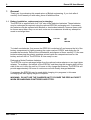
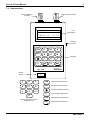
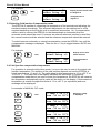
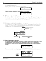
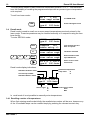
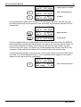
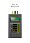
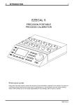
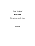
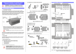
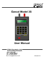
Ezecal Model 3S
User Manual
FGH Controls Ltd
Openshaw Way,Letchworth
Herts. SG6 3ER
Tel: (01462) 686677
Fax: (01462) 480633
Email: [email protected]
www.fgh.co.uk
Ezecal 3S User Manual
1
EZECAL 3S User MANUAL
Contents
1 General.
1.1 Battery installation, replacement and recharging.
1.2 Nomenclature.
1.3 Connecting the EZECAL in simulation mode.
1.4 Using the keyboard.
2 Setting up the EZECAL.
2.1 Setting the thermocouple type.
2.2 Selecting the temperature units.
2.3 Selecting Cold junction Compensation mode.
2.4 Cold junction compensation temperature.
3 Thermocouple simulation.
3.1 Simulation mode display indications.
3.2 Manual temperature simulation.
3.3 Learn Mode.
3.3.1 Programming a series of temperatures.
3.4 Recall mode.
3.4.1 Recalling a series of temperatures.
4. Specifications.
4.1 Physical.
4.2 Electrical.
4.3 Conformity Table.
2
2
3
4
5
6
6
6
7
7
8
8
8
9
9
10
10
12
12
12
12
M47 Issue 1
2
1
Ezecal 3S User Manual
General.
Thank you for purchasing this superb piece of British engineering. If you look after it
carefully it will reward you with many years of faithful service.
1.1 Battery installation, replacement and recharging.
The EZECAL is supplied with 4 off "AA" size nickel cadmium batteries. These batteries
may be recharged as required using the optional EZECAL recharging unit. If necessary
the batteries may be replaced with alkaline or zinc/carbon batteries, however these must
be thrown away when they run out and, under no circumstances should any attempt be
made to recharge them.
-
+
Cell size
AA
R6
MN1500
To install new batteries, first ensure the EZECAL is switched off and remove the lid of the
battery compartment by lightly pressing the region marked "OPEN" and sliding the lid
towards the terminals. Remove the old batteries and dispose of them carefully. Fit the new
batteries observing the polarity markings printed inside the compartment and on the
battery and refit the lid. The EZECAL is now ready for use.
Recharging Nickel Cadmium batteries.
The EZECAL may be recharged either from the optional mains adapter or car cigar lighter
adapter. To recharge, first switch off the EZECAL and then plug the charging lead into the
side of the unit. Leave the unit for 16 hours to fully charge the batteries. The EZECAL will
provide approximately 20 hours of continuous use with freshly charged batteries.
If necessary the EZECAL may be used whilst charging is in progress, in this case
recharging will take slightly longer to complete.
WARNING. DO NOT USE THE CHARGER UNIT TO POWER THE EZECAL EXCEPT
WHEN RECHARGEABLE BATTERIES ARE FITTED.
M47 Issue 1
Ezecal 3S User Manual
3
1.2 Nomenclature.
Black (Negative)
Terminal
Red (Positive) Terminal
FGH Controls Ltd
EZECAL 3S V2.20
LCD
Display
Charging
Socket
LRN
RCL
B
7
N
8
K
4
T
5
9
E
6
Keypads
S1
+/-
R2
CLR
L
0
J 3
ENT
EZECAL
ON OFF
On/Off
Switch
B
7
N
8
K
4
T
5
E
9
LRN
Learn mode select button
6
RCL
Recall mode select button
Function select/Scoll button
S1
R2
L
J 3
+/-
Sign change/Toggle button
CLR
Clear/Backward step button
ENT
Enter/Forward step button
0
Numeric Keypad & sensor
Selection keys
M47 Issue 1
4
Ezecal 3S User Manual
1.3 Connecting the EZECAL in simulation mode.
The EZECAL unit is intended for the calibration and checking of temperature
measurement or control instruments using any of the BS 4937 standard thermocouples.
The simulator eliminates the need for thermocouple emf look up tables, tedious cold
junction calculations and temperature units.
For thermocouple simulation purposes the EZECAL unit can be connected to the
instrument under test in three different ways.
AUTOMATIC COLD JUNCTION METHOD.
The EZECAL is wired to the instrument under test in the appropriate compensation cable.
The EZECAL should be set to its AUTO cold junction mode (see section 2.3). In this mode
the EZECAL will automatically measure the temperature of its own terminals and adjust
the output emf to compensate.
Compensating cable
CJ
+
1234
MANUAL COLD JUNCTION METHOD 1
The EZECAL is wired in copper cable to a reference junction and hence in the appropriate
compensating cable to the instrument under test. For this method of connection the
EZECAL should be set to its MANUAL compensation mode and the temperature of the
reference junction entered. (see sections 2.3 and 2.4). The reference junction point can be
any stable or temperature controlled environment between -10 and +55 °C. (melting ice is
commonly used as a reference environment of 0 °C).
Copper cable
Compensating cable
+
CJ
Reference Junction
M47 Issue 1
1234
Ezecal 3S User Manual
5
MANUAL COLD JUNCTION METHOD 2
The EZECAL is wired in copper cable to the instrument under test. For this method the
simulator should be put into its MANUAL compensation mode and the temperature at the
terminals of the instrument under test entered. (see sections 2.3 and 2.4) This method of
connection is the least reliable of the three described and should only be used for rough
checking, as changes in ambient temperature will affect the readings on the instrument
under test.
Copper cable
+
-
CJ
1234
1.4 Using the keyboard.
The numeric keypad on the EZECAL is used just like a calculator. To enter a number
simply press the numeric keys in the usual order. On the first key press the existing
number will be cleared and a flashing cursor and question mark will appear. The cursor
indicates where the next number pressed will be displayed. Digits already entered will be
shifted one space to the left. The ENT key must be used at all times to enter the number,
at which point the cursor and question mark will disappear. Negative numbers are entered
by using the +/- key to negate the number entered at any time.
Mistakes can be corrected by pressing the CLR key at any time during input and reentering the correct number. Alternatively the incorrect number may be overwritten by the
correct one after pressing the ENT key.
Examples.
Entering a positive number
Entering a negative number
existing display +1000°C
S
1
+
1?
R
2
+
12?
J
3
+ 123?
ENT
+ 123°C
existing display +1000°C
S
1
+
1?
L
0
+
10?
0
+ 100?
L
+/-
- 100?
ENT
- 100°C
M47 Issue 1
6
Ezecal 3S User Manual
Correcting a mistake
Entering a number out of limits
existing display +1000°C
2
S
1
+
1?
R
2
+
12?
CLR
+
?
S
1
+
1?
J
3
+
13?
ENT
+
13°C
existing display +1000°C
S
1
+
1?
B
7
+
17?
ENT
Error
S
1
+
1?
E
6
+
16?
ENT
+
16°C
Setting up the EZECAL.
This section describes how to set up the EZECAL to simulate the particular thermocouple
of interest, the temperature units and the cold junction compensation mode.
2.1 Setting the thermocouple type.
The EZECAL can simulate three of the standard thermocouple types specified under BS
4937, these are :Pt10%Rh/Pt type S
Pt13%Rh/Pt type R
NiCr/NiAl
type K
and equivalents in °F.
-50 to 1767 °C
-50 to 1767 °C
-270 to 1372 °C
The sensor type is set by using the scroll key until the thermocouple type is displayed and
then pressing a numeric key to set the required type.
For example.
OUTPUT
Type:S
Thermocouple
S
Select S, R or K
Display shows current type
4
Now press ENT to
confirm type
K
To set type K
ENT
Thermocouple
K
Select S, R or K
To confirm change
+1760°C
CJC:Man
K
2.2 Selecting the temperature units.
The EZECAL can work in either °C or °F. To change the temperature units press the
SCROLL key until the temp units message is displayed, and then use the +/- key to toggle
between °C and °F.
M47 Issue 1
Ezecal 3S User Manual
For example.
7
Temp Units
°C
Select Using +/Temp Units
°F
Select Using +/-
until
+/-
Display shows current units
are degrees C
Changed units to
degrees F
2.3 Selecting Cold junction Compensation mode.
The EZECAL is capable of measuring the temperature of its terminals and adjusting the
simulated output accordingly. This automatic adjustment can be switched on or off as
required depending on the way the unit is connected (see section 1.4). If compensation
cable is used to connect the EZECAL to the thermocouple or instrument then the
automatic mode should be used. If, however an external reference junction is used then
the manual mode should be selected and the reference temperature should be entered.
To switch between automatic or manual compensation, press the SCROLL key until the
compensation message is displayed. Then use the +/- key to toggle between AUTO and
MANUAL.
For example
..
until
+/-
Cold junct auto
Select Using +/-
Display shows auto
mode selected
Cold junct
man
Select Using +/-
Changed mode to
manual
2.4 Cold junction compensation temperature.
For operation in manual cold junction mode, it is up to the user to enter in the actual cold
junction temperature. The location of the cold junction depends on how the EZECAL is
wired (see sections 1.3 and 1.4). The valid range for this temperature is -10 to +55 °C or
14 to 131 °F. The lower line of the display indicates the valid range. In Automatic
compensation mode there is no need to enter this temperature, the EZECAL will measure
the temperature automatically and its value will be shown on the display. If this measured
temperature is outside the specified limits of -10 to +40 °C (or equivalent) and error
message will be displayed.
for example in MANUAL CJC mode.
..
until
CJ Temp + 24.0°C
From -10 to 55°C
2
CJ Temp +
.2?
From -10 to 55°C
N8
CJ Temp + 2.8?
From -10 to 55°C
T 5
CJ Temp + 28.5?
From -10 to 55°C
ENT
CJ Temp + 28.5°C
From -10 to 55°C
R
Existing CJ temp
is displayed
M47 Issue 1
8
Ezecal 3S User Manual
A new cold junction temperature of 28.5 °C has now been entered.
In AUTOMATIC CJC mode.
Display shows internally measured CJ temperature.
CJ Temp + 24.2°C
Display indicates measured CJ temperature is out of range.
CJ Temp + Error
*CJ RANGE ERROR*
3
Thermocouple simulation.
Simulation mode is used to simulate the set thermocouple type. The required temperature
is entered on the keypad and the equivalent emf with compensation if required will be
output to the terminals directly after the ENT key is pressed.
3.1
Simulation mode display indications.
Simulation mode is recognised by the word "OUTPUT" appearing on the top line of the
display. The current set-up and actual temperature being simulated is also displayed
along with any error conditions that may arise.
Simulated temperature
Temp units
OUTPUT
Type:K
Sensor Type
°C
°F
+1000°C
CJC:Auto
S
R
K
Cold Junction mode
Auto
Man
3.2 Manual temperature simulation.
In simulation mode the required temperature is simply entered on the keypad and, if valid,
will appear at the output terminals upon depression of the ENT key. If the entered
temperature is outside the valid range for the sensor selected then an error screen will
appear:-
OUTPUT
Error
* OUT OF RANGE *
This error is quickly cleared by simply pressing CLR or re-entering a valid temperature:-
OUTPUT
Error
* OUT OF RANGE *
CLR
M47 Issue 1
OUTPUT
?
* OUT OF RANGE *
Ezecal 3S User Manual
To enter a temperature for simulation. For example 1000 °C:S
1
L
0
L
0
L
0
ENT
9
OUTPUT
Type:K
+1000°C
CJC:Auto
OUTPUT
Type:K
- 200°C
CJC:Auto
Negative temperatures are also easily entered:+/-
R
2
L
0
L
0
ENT
3.3 Learn Mode.
The LEARN mode is used to program the simulator to produce a series of temperatures.
This is useful if, for instance the user wishes to check the calibration of several
instruments at various positions in their range. In this case the user could use learn mode
to teach the simulator the required list of temperatures. Then using the RECALL mode
each instrument could be checked very quickly and easily by recalling each test
temperature with a single keystroke. Alternatively the time base facility could be used to
automatically step through the sequence of temperatures without user intervention.
3.3.1 Programming a series of temperatures.
In order to teach the simulator a series of temperatures, The EZECAL must be in
SIMULATE MODE (see section 3.0). LEARN mode is activated simply by pressing the
LRN keypad.
OUTPUT
Type:K
LRN
+1000°C
CJC:Auto
Lrn 0
+
0
Enter reqd value
From Simulate mode
Enter LEARN mode
The LEARN mode display.
Value programmed for
current step
Step number 0-9
Indicates LEARN mode
Lrn 0
+1234
Enter reqd value
Learn mode can store up to 10 step values. Each step is assigned a number 0 to 9 and
this is shown on the display at all times.
To teach the EZECAL a new step value the SCROLL key should be used to select the
required step number:-
OUTPUT
Type:K
...
E
6
L
0
Until
L
0
ENT
+1000°C
CJC:Auto
Lrn 6
+
0
Enter reqd value
Lrn 6
+ 600?
Enter reqd value
Lrn 6
+ 600
Enter reqd value
Select step required
Enter step value
Use ENT to store value
M47 Issue 1
10
Ezecal 3S User Manual
The step values shown in learn mode are unitless and could be °C or °F. This allows the
user the flexibility of recalling the programmed steps with any sensor type or temperature
units required.
To exit from learn mode:-
LRN
Lrn 6
+ 600
Enter reqd value
In LEARN mode
OUTPUT
Type:K
Press LRN again to exit
+1000°C
CJC:Auto
3.4 Recall mode.
Recall mode is used to recall one or more preset temperatures previously stored in the
learn mode. These temperatures may be recalled manually or in sequence using the time
base facility.
To enter RECALL mode:-
OUTPUT
Type:K
Timebase
Off
Enable using +/-
RCL
Timebase
0.2m
Enter value reqd
Timebase
60.0m
Enter value reqd
+/-
E
6
L
0
L
0
+1000°C
CJC:Auto
ENT
Rcl 0 t + 100°C
Type:K CJC:Auto
First activate the time
base if required
Timebase activated
Enter timebase value
up to 999.9 mins
Press scroll to enter
recall mode
Recall mode display indications.
Simulated temperature
Indicates timebase active
Temp units
Current step number
°C
°F
Indicates RECALL mode
RCL 0 t + 100°C
Type:K CJC:Auto
Sensor Type
S
R
K
Cold Junction mode
Auto
Man
In recall mode it is not possible to manually enter temperatures.
3.4.1 Recalling a series of temperatures.
When first entering recall mode initially the recalled step number will be zero, however any
of the 10 available steps can be recalled simply by pressing the relevant numeric key.
M47 Issue 1
Ezecal 3S User Manual
11
E
6
Rcl 0
Type:K
Rcl 6
Type:K
+ 100°C
CJC:Auto
+ 600°C
CJC:Auto
9
Rcl 0
Type:K
+ 900°C
CJC:Auto
Initially step 0 is invoked
Step 6 recalled directly
or step 9
If the programmed values were intended to be used as a sequence, then the user may
manually step through this sequence by use of the ENT key (forwards) and the CLR key
(backwards).
ENT
CLR
Rcl 0
Type:K
Rcl 1
Type:K
+ 100°C
CJC:Auto
+ 200°C
CJC:Auto
Rcl 0
Type:K
+ 100°C
CJC:Auto
Steps forwards
or backwards
If the time base facility was enabled and a non zero time was entered then the EZECAL
will automatically step through the sequence, one step every time base period. When the
step number reaches 9 or a step value is found to be zero the step number will wrap
around to step zero again. The steps may still be recalled manually as in the above two
examples. In this case the time base will be restarted after every manual step.
If a long time base period is used it may be useful to know how much time is left until the
next step. This can be displayed if the +/- key is pressed and will appear on the bottom
display line as long as the key is held down.
+/-
Rcl 0 t + 100°C
Type:K CJC:Auto
Rcl 1
+ 200°C
Next step
2.0m
Time to next step shown
M47 Issue 1
12
Ezecal 3S User Manual
4. Specifications.
4.1 Physical.
Size uncased
Weight
Power source
Battery life
Ambient temp
Humidity
Case material
:
:
:
:
:
:
:
200 x 100 x 45mm
450g
4 x AA NiCd rechargeable batteries
approx. 20 hours continuous use
-10 to +40 °C
0 to 95%RH non condensing
Black A.B.S
4.2 Electrical.
Simulation.
Basic resolution
Basic linear accuracy
: 5uV 1 in 40000
: better than 0.05% of span
(at ref. conditions 20 °C, 50% rh)
Setting resolution
Thermocouple ranges
: 1 deg C or 1 deg F
Cold junction.
Accuracy
Resolution
Range (auto mode)
(manual mode)
CJ rejection
:
:
:
:
:
+/- 0.25 °C
0.1 °C or F
-10.0 to +40.0 °C
-10.0 to +55.0 °C
Better than 20:1
Ranges to BS4937
Type S
-50 to 1767 °C
Type R
-50 to 1767 °C
Type K
-270 to 1372 °C
and equivalents in °F
Output impedance
Max. output current
Warm up time
Output settle time
:
:
:
:
Less than 0.1 Ohms
+/- 1 milliamp
Less than 1 minute
2 seconds to 99%
Battery low detection
Recharge time
Power consumption
: 4.5 Volts
: approx. 16 hours from low bat using approved charger
: 100mW max.
4.3 Conformity Table.
TYPE
RANGE
MAX ERROR(°C)
S
-50 to 0
0 to 1767
-50 to -20
-20 to 0
0 to 1767
-270 to -220
-220 to 0
0 to 1372
1.1
1.2
1.8
0.2
1.2
2.0
0.21
0.32
R
K
The above table shows the worse case error (due to the internal lineariser) which may be expected
on the given thermocouple over the specified temperature range. The absolute error on any given
range is this error plus the error due the basic linear accuracy of +/- 0.05%.
M47 Issue 1