1
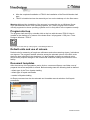
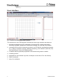
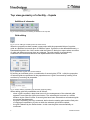
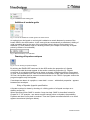
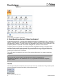
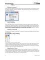
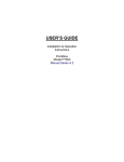
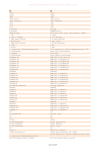
User manual
version 01/2010
Table of Contents
Program installation and the required configuration
Program start-up
Default units and use of colours
Document templates
User interface
Top view geometry of a facility – façade
Addition of elements
Editing of a modular grid
Addition of modular grids
Drawing of façade envelopes
Entry of façades by point specification
Entry of points of a façade envelope by co-ordinates
Façade editing in the top view
Moving of final points of a façade envelope
Moving of a façade envelope
Roof
Openings in a roof – a sky light
Deleting, copying and moving of a sky light
Flashing elements on the roof
Deleting, copying and moving of flashing elements
Snow-guard
Deleting, copying and moving of a snow-guard
Roof extension
Deleting, copying and moving of a joint
Dilatation on a roof
Deleting, copying and moving of dilatation
End details on a roof
Other auxiliary commands used for roof editing
Copy
Move
Delete
Mirror
Inclination
Re-set edges
3D blocs
Load-bearing element (steel columns)
Tools
Measure command
Copy command
Deleting of elements
Presentation of geometry
Magnification / Zoom
Window
Façade envelopes in a side view
Editing of façades in a side view
Façade elements
Specification of individual cladding
Specification of cladding colour
Dimension editing
Openings in façade envelopes
Drawing of windows and doors
1
2
2
2
3
4
4
4
5
5
5
6
6
7
7
8
8
8
9
9
9
9
9
9
9
10
10
10
10
10
10
10
11
11
11
11
12
12
12
12
13
13
13
13
13
14
16
17
17
17
17
verzija 01/2010
Specification of dimensions
Moving of a window / door
Flashing / detail
Copying of an opening drawn
Deleting of an opening
Overflow
Decorative profiles on façade envelopes
Deleting of decorative profiles
Copying of decorative profiles
Parapet façade
Façade base / footing
Insertion of an additional joint between cladding
End details of a façade envelope
Editing of end details of a façade envelope
Editing of a façade profile
Top and bottom edge
Other auxiliary commands used in façade editing
Presentation of the second envelope
Transition to a top view
Ground
Presentation of a model in 3D
Navigation in a 3D window
Magnification / Zoom
Possibilities in a 3D view
Capture
Export
Navigation by a keyboard
Lists of items
Survey of material in a list of items
Print-out of lists of items
Printing of lists of items
Useful functions and dialogues
Data about the project
Program settings
Undo / Redo
Program menu
New file
File opening
Saving of files
Help
Program information
Exit
Video practical exercises
17
17
17
18
18
18
19
19
19
19
20
20
21
21
22
22
23
23
23
23
24
25
25
25
26
26
26
26
26
26
27
27
27
28
28
29
29
29
29
29
29
30
30
verzija 01/2010
TrimoDesigner WIN, version 2.0
Introduction
The TrimoDesigner WIN software (hereinafter referred to as TDW) is intended for architects,
design engineers, investors and commercial clerks. By means of the program it is possible to
easily and quickly prepare an offer model of a facility including a spatial presentation of a 3D
computer model of the facility and elaboration of a list of items for Trimo façade and roof
products with standard flashing end details.
The programme includes sets enabling the following activities:
- entry of the top view geometry of a facility
- entry of Trimo products per various façade envelopes and roofs
- entry of openings in the façade cladding and roofs
- entry of decorative elements in the facility
- specification of Trimo standard flashing end details
- preview of visualisation of the 3D model of the facility with the possibility of changing the
point of view on a model
- entry of 3D blocks as an addition to the visualisation (car, tree, etc.)
- definition of the ground type and the slope
- print-out of the list of items of the installed quantities of Trimo products
The software has been made in the Slovene and English language. Instructions for the
installation and software use are presented in the following sections.
Program installation and the required configuration
Minimal requirements
The following minimal configuration is recommended for the installation of the programme:
•
•
•
Windows XP SP3 or a later version,
600 MB space on a hard disk and
a graphics card supported by Shader Model 1.1 and DirectX 9.0c.
Program start-up
The start-up depends on the operating system and corrections loaded on a computer. The
installation procedure will automatically detect the missing program libraries and install them.
Due to this fact re-starting of the system may be necessary during the installation procedure.
In this case the installation of TDW 2 will be carried out after the re-start of the system. The
installation procedure is as follows:
• Start a file "setup-2.x.y-full.exe" (x and y are the corresponding numbers of the
•
•
1
version).
When extracting of files has been finished, the installation procedure will
automatically start. This procedure checks the presence of the required program
libraries. The questions asked during the installation procedure shall be answered by
"Accept" or "Install". WARNING: at this stage the installation procedure may several
times require re-starting of the operating system. It is of vital importance for the
successful installation to allow the re-start. The installation procedure will
automatically continue after the re-start.
When all the required program libraries have been installed, the installation procedure
for TDW2 starts. The questions asked shall be answered by Next or Finish.
Version 01/2010
• After the completed installation of TDW 2 the installation of the DirectX libraries shall
•
start.
TDW 2 is installed and can be started by an icon on the desktop or in the Start menu.
Warning: Although the installation of the program is successful also on Windows Server
2003 and Windows Server 2008 operating systems, the TDW 2 program has not been
officially supported on these operating systems and it is likely that it will not operate correctly.
Program start-up
The program shall start-up by a double-click on the icon with the name TDW 2.0 that is
located on the desktop or by means of the button Start / all programs / CGS plus / Trimo
Designer Windows / TDW 2.
Fig.: The icon for the start-up of the program - TrimoDesigner WIN 2.0.
Default units and use of colours
Default units for measuring of length are millimetres and units measuring slopes / inclinations
are degrees. The program enables selection among the selected colours of the RAL scale
that have been specified in the data base. It is also possible to define an optional colour,
which usually requires changes in the commercial conditions relating to the erection of the
facility.
Document templates
After the start-up of the programme and a click on a command Open a new folder a set of
prepared document templates is offered. Before drawing starts the following shall be defined:
- default type of the Trimo façade cladding
- default type of façade end details
- material of façade cladding
An Empty command can be also selected and it enables manual selection of all façade
parameters.
2
Version 01/2010
User interface
Fig. 1: Sections in the TrimoDesigner WIN 2.0 program
The screen area in the TDW program is divided into seven logic sections and these are:
1. document management menu (elaboration of a new project, opening and saving /
archiving of projects, properties of a document, settings, etc.) and the undo function
2. commands for the entry of elements (envelope, roof, 3D blocks, load-bearing elements,
etc.), editing of elements (copying, deleting, measuring), view selection (side-view, 3D)
and monitoring of a view on a drawing (zoom)
3. a window with the presented properties of the element being drawn or edited
4. a drawing surface
5. sheet tabs for view selection (top view, envelope in a side view, 3D or list of items)
6. SNAP commands
7. entry of co-ordinates
3
Version 01/2010
Top view geometry of a facility – façade
Addition of elements
Fig. 2: Icons in the section for drawing of elements in the top view
Grid editing
Fig. 3: Icon for editing of modular grids in the “Add” section
When the program has been started a new project with the prepared division of modular
grids at a distance from each other of 5000mm opens. If grids are to be defined differently, a
command Set grids in the “Add” section shall be clicked. A dialog box opens where a number
of grids and distances among them are selected. The grid program is automatically
numbered in the horizontal direction and alphabetised in the vertical direction.
Fig. 4: Specification of grids at a constant distance
By clicking an individual grid or a combination of several grids (CTRL + click) the properties
of selected grids are presented in the properties area. A grid is corrected by marking it first
and then by correcting its properties.
Fig. 5: Section with the properties of the selected grid during editing
When editing grids the possibilities are as follows:
- when a grid is marked, a drop-down menu for the management of the selected grids
appears if one clicks the right mouse button. The selected grid is moved to a certain
distance by the “Move” button. If several grids have been selected then all selected grids
are moved simultaneously;
- the grid is copied by the Copy command; before that the starting point and the final point
of copying are specified or a point to which the selected grid shall be copied;
- the grid is deleted by the Delete button. In this case the grids are automatically renumbered.
4
Version 01/2010
Fig. 6: Possibilities when editing grids
Addition of modular grids
Fig. 7: Icon for the addition of modular grids in the “Add” section
An optional new horizontal or vertical grid is added at a certain distance by means of the
button GRID in the ADD section. In this case grids are automatically re-numbered. Adding of
grids is possible also by the entry of the numerical value in the box for the entry of coordinates (7) at the bottom edge of a drawing surface (see Chapter on the Entry of façade
points by means of co-ordinates).
Fig. 8: Box for the entry of co-ordinates
Drawing of façade envelopes
Fig. 9: Icon for drawing of façade envelopes
By clicking the ENVELOPE command in the ADD section the properties of a façade
envelope that shall be drawn appear in the section containing properties (3). Façade
envelopes of an individual facility can be drawn as closed, completed polylines (line system)
or open, non-completed ones. Due to the correct orientation of the view on the envelope in a
3D view, the façades shall be entered counterclockwise. In the TDW 2.0 program version the
program supports only flat façades.
If envelopes are drawn in a polyline, a new detail – corner – with default properties - appears
between two envelopes.
Entry of façades by point specification
A façade envelope is drawn by showing viz. clicking points of a façade envelope on a
drawing surface (4).
When specifying points SNAP in section 6 may also help. SNAP is described in detail in
Chapter 6. If - for example - one wants to select central points on façades, the possibility
Façades and then Centre shall be marked. Then the Façade command shall be on so that it
appears as selected (the figure below).
5
Version 01/2010
Fig. 10: Selection of SNAP setting on a façade
If one wants to complete the present polyline while drawing, click the right mouse button and
select the Close command from the drop-down menu. When polylines are entered clockwise
the program warns about the incorrect direction.
Fig. 11: A drop-down menu shown after clicking the right mouse button
If a mistake is made while entering points, the last entry can be undone by clicking the right
mouse button and selecting the Back command. The program will undo the last entry of the
point.
Entry of points of a façade envelope by means of co-ordinates
An alternative possibility of specifying façade points is pressing any figure on a key-board
during drawing. Thereby, the entry in the field for specification of co-ordinate points is
possible (section 7). Firstly, the X co-ordinate of the following point is entered in the field,
then one moves to the field for the specification of the Y co-ordinate by the TAB key (or by
clicking the mouse) and enters the co-ordinate. The entry of the point is confirmed by
ENTER. The entry of points of the following façade continues.
Possibilities in the box for the entry of co-ordinates:
- if P is pressed during the entry of a point, when a box for the entry of co-ordinates is
visible, one switches between the orthogonal (X and Y are given) and polar (the length
and angle are given) entry. The TAB key (X and Y) is used for switching between both
individual co-ordinates;
Fig. 12: Orthogonal mode of co-ordinate entry
-
Fig. 13: Polar mode of co-ordinate entry
if the R key is pressed while entering a point in the box for the co-ordinate entry, one
switches between the relative (relating to the starting point) and the absolute (relating to
the previous point) entry.
Fig. 14: Box for the entry of co-ordinates as help when entering points
Façade editing in the top view
If one wants to see properties of a certain façade envelope in a top view, it is sufficient to
click the selected envelope. All properties of the envelope are shown on the right side of the
screen, in the properties section where individual properties of a façade envelope can be
also edited. The following properties can be defined and edited on the envelope:
- Height: the actual height of a façade envelope
- Façade height: the bottom point of the façade envelope
- The appearance and colour of the façade envelope: it is the façade colour and thus also
the colour of the cladding
6
Version 01/2010
-
Appearance of the material: specification of the material of the façade envelope and
joints used among the cladding (it does not apply in case when glass or concrete are
selected as material)
Fig. 15: Section containing properties for editing of a façade envelope
Moving of final points of a façade envelope
Initially, an envelope whose point is to be moved shall be selected for moving an individual
point of the façade envelope on a polyline. Then a point (handle) that is to be moved shall be
clicked. The handle that is to be moved is painted red and then the final point of moving is
specified.
Fig. 16: Moving of the final point of the façade envelope
Moving of a façade envelope
When moving an individual façade envelope a drop-down menu is initially selected and
opened by clicking the right mouse button where the Move function is selected. First, the
starting point and then the final point of moving are shown. The line of the envelope is always
presented parallel to the starting position.
The façade envelope can be moved also by marking it and selecting a central handle. This is
the basic point of moving an envelope in this case.
If the façade envelope is part of a polyline, the geometries of the neighbouring façades are
updated automatically and adjusted to the new situation.
7
Version 01/2010
Fig. 17: Selection of a function for moving a façade envelope
Roof
When clicking the Roof command one gets to the entry of points by means of which the roof
is defined. When entering of the edge points of a roof has been completed a drop-down
menu appears when clicking the right mouse button. The End command is selected from the
drop-down menu. After clicking the command a roof is drawn under consideration of the
selected points.
Fig. 18: A descending menu when clicking the right mouse button while drawing a roof
When clicking the roof drawn commands used for roof editing appear in the section
containing properties. Individual properties of the roof can be changed by clicking an
individual menu.
The internal and external colour of a roof and the roofing material can be selected in the box
containing properties of the roof, precisely in the section Appearance. The roof inclination,
height of the roof ridge and the eaves / dripping edge length can be selected in the Geometry
section.
Fig. 19: Box containing the properties of a roof
The commands presented below are used for the addition of elements.
Fig. 20: Section with additional elements for editing roofs
8
Version 01/2010
Openings in a roof– a skylight
A command for roof selection appears when clicking a Skylight button in the command bar.
On such roof a selected opening shall be drawn. Initially, the first point of the opening entry is
shown (the point can be shown only within the roof) and then also the (diagonal) final point of
the opening. The properties may be edited in the box containing properties on the right
screen side where the selected skylight can be edited. When clicking the selected skylight it
may be optionally moved over the roof.
Deleting, copying and moving of a skylight
The selected skylight is marked by clicking the left mouse button and the drop-down menu is
opened by clicking the right mouse button. It enables moving, copying or deleting of the
selected opening.
Openings can be also corrected by marking and moving of handles.
Flashing elements on a roof
A command for roof selection appears in the command bar when clicking the button Detail on
the roof. A flashing element (line) shall be drawn on this roof. Then the starting point (the
point can be shown only within the roof) and the final point of the line entry are shown. The
properties can be edited in the box containing properties on the right side of the screen
where the selected flashing element can be edited. When the flashing element is to be
moved, it is marked and by clicking a handle it is optionally moved over the roof. The flashing
element (line) can be only flat.
Deleting, copying and moving of flashing elements
A decorative line is marked by clicking the left mouse button and a drop-down menu is
opened by clicking the right mouse button. The menu is used for moving, copying or deleting
of the selected flashing element.
Flashing elements on the roof can be corrected also by marking and moving of the handles.
Snow-guard
By clicking a Snow-guard button a command for roof selection appears in the command bar.
A snow-guard shall be drawn on this roof. The starting and the final point of the snow-guard
are then defined. Properties can be edited in the box containing properties on the right side
of the screen where the selected snow-guard can be edited. The snow-guard can be
optionally moved over the roof by a double-click on the selected snow-guard (line). The
snow-guard can be only flat.
Deleting, copying and moving of a snow-guard
The selected snow-guard is marked by clicking the left mouse button and a drop-down menu
is opened by clicking the right mouse button. The menu is used for moving, copying or
deleting of the selected snow-guard.
Snow-guards can be corrected also by marking and moving the handles.
Roof extension
A command for the selection of the roof on which an extension is to be defined appears in
the command bar when clicking a command. An extension point is defined; it is always
rectangular to the roof inclination. The program considers this as an extension of cladding by
9
Version 01/2010
20 cm. The properties can be edited in a palette on the right side of the screen (an extension
detail is defined). A double-click on the selected joint (line) enables its free movement over
the roof. The extension of cladding is carried out in a straight line over the complete roofing.
Deleting, copying and moving of a joint
Clicking the left mouse button marks the selected joint and clicking the right mouse button
opens a drop-down menu. This menu is used for moving, copying or moving of the selected
joint.
The extension of cladding can be corrected also by marking and moving of handles.
Dilatation on a roof
A command for roof selection appears in the command bar when clicking a Dilatation
command. Dilatation shall be defined on this roof. A dilatation point is specified and it always
runs parallel to the direction of the roof inclination. Properties can be edited in the box
containing properties on the right side of the screen where the selected dilatation can be
edited. Dilatation (line) can be freely moved over the roof by a double-click on the selected
dilatation. Dilatation of the roof can be only flat.
Deleting, copying and moving of dilatation
The selected dilatation is marked by clicking the left mouse button. A drop-down menu is
opened by clicking the right mouse button. The menu is used for moving, copying or deleting
of the selected dilatation.
Dilatation can be also corrected by marking and moving of the handles.
End details on a roof
Properties of the selected end detail appear in a palette when clicking the selected end
detail. The selected end detail is to be edited. An individual end detail of the roof can be
deleted so that the program does not consider it in a 3D drawing and print-out of a list of
items (e.g. when 2 roofages share the same edge).
Other auxiliary commands used for roof editing
Some general auxiliary commands for roof editing are listed also in the drop-down menu. A
roof is marked by clicking the left mouse button and a drop-down menu with the selected
commands for additional roof editing appears by clicking the right mouse button.
Fig. 21: A drop-down menu for roof editing
Copy
When clicking the Copy command the starting point is selected. From this point the roof shall
be copied. Then the final point is selected where the roof shall be copied.
10
Version 01/2010
Move
By clicking the Move command the staring point of moving the roof is selected. Then the final
point where the roof shall be moved is specified.
The roof can be also moved by marking and moving the handles.
Fig. 22: Moving of a roof by means of handles
Delete or the Delete key
A roof is irrevocably deleted when clicking the Delete a roof command.
Mirror
Both points of an apparent line are defined by clicking the command. The roof shall be
copied over this line. When the second point has been defined, the roof is automatically
copied as a mirror to the other side of the apparent line drawn.
Inclination
Initially, the first point of the inclination is specified by clicking the command for the definition
of roof inclination. This first point simultaneously represents the top of the ridge. Then the
direction into which the inclination will descend (a red arrow on the roof shows the direction
of the inclination) is specified in relation to the selected point of the ridge.
Re-set edges
The program automatically restores the deleted end details of the roof when this function has
been used.
3D blocks
By means of this function the desired additional objects are inserted in the top view: different
trees, people, parking slots or a car, a bus, a truck. The inserted 3D elements are used for a
realistic presentation of an object / a facility in a 3D view.
The desired block is selected; a point is shown where the block is to be placed in the top
view.
11
Version 01/2010
Fig. 23: Menu for the addition of 3D blocks
A load-bearing element (steel columns)
Load-bearing elements – columns as an additional structure or substructure (e.g. useful for a
canopy / projecting roof) are inserted in a picture by means of this function. Default elements
are inserted in a project - I column profile, but the shape of the column can be changed in the
properties palette. The profile can be also changed to a square or round column.
A square column and I profile can rotate round their longitudinal axis by a complete circle
when the Rotation attribute is changed. When entering the degrees of the inclination the
inclination of the column relating to the X-Y plane is defined - e.g. a support is drawn by
entering the inclination of 90 degrees.
The profile size is changed by the entry of the desired dimension in a palette containing
properties.
Hint: round and square columns can be also used for the presentation of
neighbouring objects in real situations, but only as geometrical elements or figures
without details.
Tools
Icons for general tools are shown in the menu bar in the top or side view. They enable quick
access to general functions for editing of the objects drawn.
Fig. 24: Sections with tool icons
12
Version 01/2010
Measure command
When clicking the Measure command the program requires showing of two points by means
of which the program calculates a distance. The measurement is written in a box placed in
the middle of the screen.
Fig. 25: The length measured
Copy command
When clicking the Copy command it is possible to copy the complete element with all the
properties and additional elements. At this command the program requires in the command
bar the specification of a point from which it will be copied (Copy: show the first point) and
then the point in which the element shall be copied (Copy: show the second point). Several
elements can be copied simultaneously, if several of them are marked.
Deleting of elements
An element to be deleted is specified. The element is permanently deleted when the Delete
icon is clicked.
Presentation of geometry
Fig. 26: Selection of a view on a façade envelope
Icons for a view are shown in the menu bar in the top view. They enable quick access to an
overview of individual façade envelopes in the side view or an overview of the complete
object in 3D. An envelope that one wants to see is selected for the overview of an individual
envelope in the side view in the drop-down menu.
Magnification / Zoom
When a view of a certain part of a drawing is to be zoomed, the mouse (or scroll) wheel is
scrolled up or down to get a larger or smaller detailed picture. When clicking the Border icon,
one gets back to the default view. Zoom icons are presented in the menu bar in the top and
side view and enable various types of zooming a drawing.
13
Version 01/2010
Window
Fig. 27: Section with icons for zooming a drawing
When clicking the Window / box command, a certain part of the complete drawing appears in
the screen. In the command bar the program requires showing of the first point of the desired
frame and then the other diagonal point. Zooming will be then automatically drawn in the
screen. When clicking the Border icon, one gets back to the pre-set view.
Façade envelopes in the side view
Editing of façades in the side view
There are three possibilities to get to the side view: the first one is through the Side view
menu in the menu bar (Section 2) where an envelope to be edited is selected in a
descending menu. The second possibility is through sheet tabs for the selection of the view.
The third possibility is marking a façade in the top view and selecting Show side view in the
drop-down menu.
Fig. 28: Selection of a façade envelope view
New sections appear in the menu bar upon the transition to the side view; these sections
contain façade elements (cladding, windows, doors, overflows, etc.) and Views for quick
editing of views and the standard sections Zoom and Tools.
Fig. 29: Section with properties during the editing of façades in the side view
Façade elements
A dialog box appears when clicking the Façade element command. The type of a façade,
details of a joint and dimensions of cladding for the complete polyline can be selected from
the box.
When starting a new project, default cladding and cladding that has already been added to
the project appear in the list. If new composition is to be added, click the New element
button. When the selected composition is to be edited, click the Edit element command.
14
Version 01/2010
Fig. 30: Dialog box for specifying dimensions, types and extensions of cladding
Definition of the composition
When selecting the Edit element command a dialog box appears. Type, dimensions of
materials, thickness and protection of the cladding are defined by means of this box.
Fig. 31: Menu containing commands for specifying and editing of cladding
15
Version 01/2010
Fig. 32: Properties when defining cladding
The following properties are selected in the dialog box for editing of cladding:
- system: types of sheet metal depend on the selected system
- colour protection
- sheet metal type (shape)
- sheet metal thickness
- cladding thickness
Fig. 33: Dialog box for editing of cladding composition
When clicking the New element button in the drop-down menu for a Joint detail in the Façade
elements dialog box, a new box opens where the desired detail of a joint between cladding is
selected.
16
Version 01/2010
Fig. 34: Dialog box for the selection of a type of joining cladding
Specification of individual cladding
When selecting composition of individual cladding, cladding is marked in the side view and
the type of cladding is selected from the list in the palette containing properties.
Specification of cladding colour
When changing the colour of individual cladding, an element is marked and the type and
colour of the cladding are specified in the palette containing properties.
Dimension editing
When changing dimensions of individual cladding, an element is marked and dimensions are
specified in the pallet containing properties (width).
Fig. 35: Changing of properties of individual cladding
17
Version 01/2010
Openings in façade envelopes
Openings for façade envelopes are specified in the Section Façade elements. Round and
rectangular windows and doors can be drawn separately and openings are made in façade
envelopes.
Fig. 36: Menu icons for the entry and editing of openings
Drawing of windows and doors:
The first point representing a reference point for window drawing is entered by clicking the
Window / Door command. Then the second point (diagonal) is entered and a window / door
is drawn.
Specifications of dimensions
Of a drawn window/door: a window/door is marked by clicking so that handles of the
window/door are painted red. Then the new dimensions of a window/ door are specified.
Moving of a window/door
A window/door is marked and a drop-down menu is opened by clicking the right mouse
button where the Move command is selected. First the starting point and then the final point
of the move are specified.
Windows / doors can be also moved by the use of handles.
Flashing / detail
A detail of the opening installation has to be specified as well. If the opening detail in the
default mode, in the element properties is not correct, it is simply changed by clicking the
New element where a new desired detail of flashing is specified.
Fig. 37: Dialog box with properties of an opening
18
Version 01/2010
Fig. 38: Dialog box for the selection of a detail for opening installation presenting where it is possible to switch-off
a filter
Copying of an opening drawn
A Copy command in the drop-down menu is selected by clicking the mouse right button on
the opening marked. The first point functioning as a starting point is then shown. Then the
target point is shown where the opening shall be copied. The selected opening can be
copied only once. If one wants to copy several elements as a time, all desired elements are
to be marked and then the starting point and the target point of copying are specified.
Deleting of an opening
If one wants to delete a certain opening, it is firstly marked. A drop-down menu is opened by
clicking the right mouse button and the Delete command is selected.
Overflow
By clicking the Overflow command in the side view a point is specified where an overflow
shall be inserted through certain cladding.
The properties of the overflow are specified in the properties section. Various details and the
colour of the flashing are specified. The overflow can be specified only when the roof has
been drawn above the façade envelope. The overflow will be always drawn above the height
of the roof drawn.
Decorative profiles on façade envelopes
By clicking the Decorative lines button a command for the specification of the first point of
entry of a decorative profile (the point can be shown only within the borders of the envelope)
appears in the command bar. Then the final point is specified. The properties can be edited
in the box containing properties on the right side of the screen where the selected decorative
profile can be edited. By a double-click on the selected detail (line) it can be freely moved
over the envelope. The decorative profile can be only flat.
19
Version 01/2010
Fig. 39: Icon for drawing of decorative profiles
Deleting of decorative profiles
If a decorative profile is to be deleted, it is marked. A drop-down menu is opened by clicking
the right mouse button where the Delete command is selected. The line is permanently
deleted by clicking the Delete command.
Copying of decorative profiles
If a decorative profile is to be copies, it is marked first. A drop-down menu is opened and the
Copy command is selected. When the line has been marked a drop-down menu is opened
by clicking the right mouse button where the Copy command is selected. Then the first point
functioning as the staring point is shown and then the target point where the decorative
profile shall be copied. The decorative profile can be only flat.
Parapet façade
By clicking the Parapet façade command in the side view a section is specified that is shown
above the roof – parapet.
The command automatically switches to the view used for editing of a profile of the façade
envelope where cladding is hidden in order to be able to edit points easily. When doing this
the Edit façade button gets coloured (activated). The properties of the parapet material are
specified in the section containing properties. Flashing and the material of the parapet façade
can be specified. A pre-set material is sheet-metal in a thickness of 0.6 mm.
The parapet façade is specified only when the roof has been drawn.
Fig. 40: Drawing of a parapet façade in the view used for editing of a façade profile
Façade base / footing
A dialog box for the specification of a base appears by clicking the Façade base command.
Shape, height and colour are selected in a dialog box. A façade base shall be specified for
each façade separately.
20
Version 01/2010
Fig. 41: Dialog box for the specification of a base
Fig. 42: Façade base
Insertion of an additional joint between cladding
The Insert a joint command is used for inserting an additional joint. A point is shown where
the joint shall be made. The joint is always shown exactly rectangular to the flow of the
cladding (vertical, horizontal) and can never run diagonally.
End details of a façade envelope
A line Left / Right corner is selected in the palette containing properties and a type of detail is
selected from the drop-down menu. This is possible only when the selected façade is in the
top view and when the façade is presented in the side view.
If one would like a detail that is not in the list, the New element is selected where the desired
detail and the desired colour are selected in the section containing parameters. It is also
21
Version 01/2010
possible to edit the existing definition of a detail (a button in front of the selected detail in the
drop-down menu). If none of the details is wanted, a possibility Without is added.
Fig. 43: Dialog box for the selection of flashing
Editing of end details of a façade envelope
By clicking a detail presented in the picture the properties of the Corner detail appear on the
right side of the Properties menu – Corner detail in the side view of the selected envelope. A
descending menu containing the selected details appears by clicking the description of the
detail. If another end detail is desired, the New element is clicked where the desired element
is selected from the list and the desired colour from the section containing parameters.
Fig. 44: A descending menu for editing of façade edges
Left and right edge
The left and right edges that are to be edited are selected by a combination of clicking
individual edges in the picture and a Control (CTRL) key. When editing details have been
selected, the properties of the corner detail appear on the right side of the menu Properties –
22
Version 01/2010
Corner detail. When clicking the detail description a descending menu appears where the
details have been selected. If another end detail is desired, click the New element where a
desired detail is selected from the list and the desired colour from the section with
parameters.
Editing of a façade profile
Fig. 45: The view mode for editing of a façade profile is ON
Click the menu - Editing a façade profile - in the side view. A schematic presentation of a
façade is drawn and the cladding is hidden. Here, dimensions and the inclination of the top
and bottom façade edges can be changed. None of the corner end details of a façade
envelope can be specified in this view. The cladding is shown again by clicking the icon for
Editing of a façade profile and then the schematic mode of façade presentation is OFF.
Top and bottom edges
An outline of an envelope appears in the side view by clicking the command - Edit the façade
profile. Handles are activated by the edge selection (top or bottom edges). By means of
handles the top of the point is edited (a handle is moved up and down). In this way an
optional façade shape (e.g. front façade of a saddle roof) can be created. The length of the
façade cannot be changed in this view. Maximal height of the envelope has been specified
by drawing it. Intermediate points can be specified on each top or bottom edge if the façade
edge is to be drawn in different types of inclination, planes or combinations.
Fig. 46: An example of specification of a façade shape with the adjustment of top and bottom edges
23
Version 01/2010
Other auxiliary commands used in façade editing
Presentation of the second envelope
By clicking the button << or >> the neighbouring façade envelope appears within the same
polyline. If an envelope is to be drawn in the side view that is a component of another
polyline, this can be done by selecting it in the envelope list.
Fig. 47: Section with icons for view changing
Fig. 48: List of façade envelopes
Transition to a top view
A project appears in the top view when clicking the top view button.
Ground
Fig. 49: An icon bar in the view used for drawing ground
If the ground around the facility is to be drawn, the ground in the bottom sheet tab is
selected. The Draw ground menu is offered in the menu bar. The first point of the ground is
selected and then the second (diagonal) point of the ground. The basic square is divided into
triangles relating to the properties of Number of divisions. The accuracy level needed for the
specification of inclinations or ground structure is specified by this property. If flat ground with
the same ground structure is desired the division 1 -1 is sufficient (1 triangle vertically and 1
triangle horizontally).
Fig. 50: Division of the ground into triangles
The default height of the area equalling 0 is written in the left top corner of each triangle of
the ground. This is the peak of the small square or the peak that may be common to a
maximum of 6 triangles. The height can be changed by marking the number and by entering
24
Version 01/2010
the desired height of the ground point in the Properties menu. If the height of the major part
of the ground is to be changed at once, several points are marked simultaneously (by
clicking and the control key - CTRL) and then the height in Properties is corrected.
Each square of the ground is diagonally divided into two triangles where the composition of
the ground can be changed (type of ground). On top of the default possibilities of the ground
the others include also asphalt, brick (paving stones) or water.
The size and position of the central area can be optionally changed by clicking the edge of
the ground by which it is marked and by a re-clicking the point used for changing of the
ground size.
The icons in the bar menu enable returning from the view for ground drawing to a top view,
side view or 3D view of the model any time.
Presentation of a model in 3D
By clicking the 3D model command in the section View (2) a new window opens where a 3D
model of the facility is drawn.
Fig. 51: Window for the presentation of the facility in 3D
Navigation in a 3D window
Magnification / Zoom
By pressing a cursor-moving key (forward) ↑ one gets nearer to the model and by pressing
the key backward ↓ one gets always from the model. One always moves in the direction of
25
Version 01/2010
the view or actually one moves as if it floated in the air. The screen centre is set by clicking
the left mouse button and moving the mouse in the desired direction.
Possibilities in a 3D view
Fig. 52: Section with possibilities of the present view in the 3D view
Capture
The Capture command opens a diagonal box where the location is selected. The picture of
the present view shall be saved in this location. The picture can be only saved as a .jpg file,
which can be opened on each computer; it is easily transferrable also when sending it via
electronic media (e-mail,…).
Export
The Export command opens a dialog box where the location is selected where the complete
file shall be saved. A picture can be saved only as a *.obj file and is intended for the export of
a 3D model for processing in more advanced programs for the elaboration of visualisation
(Autodesk 3ds Max, Google SketchUp,…).
Navigation by a keyboard
The Starting point command always places our view on the starting point in the 3D view.
The keys A, W, D and S replace the cursor-moving keys:
A: left
D: right
W: forward
S: backward
The keys J, I, L and K are responsible for turning round their grinds and replace moving by a
mouse:
J: turn to the left
L: turn to the right
I: turn upwards
K: turn downwards
The scroll box – Moving speed (the speed of moving) specifies the speed of moving in a 3D
view.
26
Version 01/2010
Lists of items
Survey of material in a list of items
With the transition to the view of the list of items, a form with all the data about the project is
printed; it includes also all the materials and details used in the present project.
Fig. 53: Section with the possibilities of the list of items
Print-out of lists of items
If a list of items is to be exported to Excel, click the command To Excel; a new dialog box
opens where the place for saving on a disk is selected. A file is always saved in .xls format.
If the list of items is to be exported to Acrobat Reader, click the command To PDF; a new
dialog box opens where the space for saving on a disk is selected. A file is always saved in
*.pdf format.
Fig. 54: An example of a printed-out list of items
Printing of lists of items
A list of items can be printed by a Print command. A dialog box opens and a printer where
the list of items is to be printed shall be selected.
Before the list of items is printed, a print-preview or the list of items on a paper can be viewed
by clicking the Preview command.
The Preview size can be edited by the Zoom command in the drop-down menu, where the
desired size of the Preview on the screen is selected.
Moving over sheets of paper shown on the screen is possible by the keys I<, <<, >>, >I.
27
Version 01/2010
Useful functions and dialogues
Data on the project
By clicking the Trimo icon and then Document properties a dialog box opens. In the first
sheet tab (Data about the project) data about the project are entered and they shall be visible
also on the print-out of the list of items.
The exterior and interior colour, the system and the width of selected cladding are selected in
the second sheet tab (default details). Values and properties selected are considered in
drawing as a default selection of materials.
Fig. 55: Menu for editing of document properties
Program setting
Other possibilities for editing work in the TDW program can be found under the Section
Possibilities where the colours for drawing of individual surfaces: façades, roofs, details,
snap editing, setting of program presentation and drawing surface can be selected.
28
Version 01/2010
Fig. 56: Dialog box for the selection of colour display
Undo / Redo
When clicking the Undo command, the program always restores the situation of the drawing
before the last function used. If one wants to return back to the original situation, the Redo
function is used.
The Undo function does not exist in the 3D view.
Program menu
Fig. 57: Program menu
29
Version 01/2010
New file
By clicking the File menu and then New, the program creates a new file originating in the
Document Templates where the initial settings of details and materials have been specified.
The values of the present template are edited in the dialog box – Possibilities - Templates.
File opening
When clicking the File menu and then Open, a saved project is opened.
Saving of files
By clicking the File menu and then Save, the opened project is saved under a pre-set name.
If a file name is to be changed while saving, click the Save as command and enter the file
name in the dialog box and specify the name where the file shall be saved. The file saved
has a 3mo file extension.
Help
The File menu contains a Help icon with basic help information relating to the use of program
functions.
Program information
When clicking the icon - Information about the program - in the File menu one sees which
version of the program has been used and if a new program version is available on the
Internet that can be downloaded.
Exit
The work in the TDW program ends by clicking the Close command.
Video practical exercises
Presentation of the basic commands and the course of drawing for two reference facilities
are offered as help during quick learning. A video record of drawing a Trimo facility is
available in the annex:
- Single-pitch roof
- Complex facility with a saddle roof
30
Version 01/2010