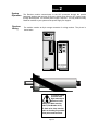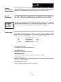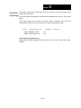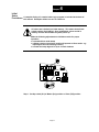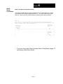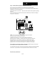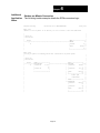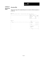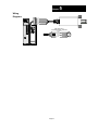
1
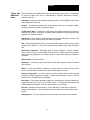
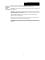
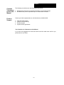
Important User Information
Solid state equipment has operational characteristics differing
from those of electromechanical equipment.
“Safety
Guidelines for the Application, Installation and Maintenance of
Solid State Controls” (Allen-Bradley Publication SGI-1.1)
describes some important differences between solid state
equipment and hard-wired electromechanical devices.
Because of this difference, and also because of the wide variety
of uses for solid state equipment, all persons responsible for
applying this equipment must satisfy themselves that each
intended application of this equipment is acceptable.
In no event will the Allen-Bradley Company or Helm Instrument
Company be responsible or liable for indirect or consequential
damages resulting from the use or application of this
equipment.
The examples and diagrams in this manual are included solely
for illustrative purposes. Because of the many variables and
requirements associated with any particular installation, the
Allen-Bradley Company or Helm Instrument Company cannot
assume responsibility or liability for actual use based on the
examples and diagrams.
No patent liability is assumed by Allen-Bradley Company or
Helm Instrument Company with respect to use of information,
circuits, equipment, or software described in this manual.
Reproduction of the contents of this manual, in whole or in part,
without written permission of the Allen-Bradley Company and
Helm Instrument Company is prohibited.
Throughout this manual we use notes to make you aware of
safety considerations.
ATTENTION: Identifies information about practices
or circumstances that can lead to property damage.
Identifies information that is especially important for
successful application and understanding of the
product.
Attentions help you:
• identify a hazard
• avoid the hazard
• recognize the consequences
PLC, PLC2, PLC3, and PLC5 are registered trademarks of the Allen-Bradley Company, Inc.
SLC, SLC500, PanelView, RediPANEL, Dataliner are trademarks of Allen-Bradley Company, Inc.
IBM is a registered trademark of International Business Machines, Incorporated.
ForceGard is a registered trademark of the Helm Instrument Company, Inc.
Revised 7-97
Table of Contents
Resolver Input Module
User Manual
Preface ............................................................................................. P-1
Who Should Use this Manual........................................................... P-1
Purpose of this Manual .................................................................... P-1
Contents of this Manual.............................................................. P-2
Related Documentation .............................................................. P-3
Terms and Abbreviations ................................................................. P-4
Common Techniques Used in this Manual ....................................... P-6
Product Support.......................................................................... P-6
Your Questions or Comments on this Manual ............................. P-6
Overview
Chapter 1 ..........................................................................................1-1
Module Components........................................................................ 1-1
Resolver Operation .......................................................................... 1-1
Features........................................................................................... 1-1
Hardware Overview ......................................................................... 1-2
Hardware Features .......................................................................... 1-3
Getting
Started
Chapter 2..........................................................................................2-1
Getting Started ................................................................................ 2-1
Required Tools and Equipment ....................................................... 2-1
System Operation ............................................................................ 2-2
Resolver Wiring................................................................................ 2-2
Channel
Configuration,
Data and
Status
Chapter 3 ..........................................................................................3-1
Channel Configuration, Data and Status .......................................... 3-1
Module Addressing .......................................................................... 3-1
Resolver Module ID Code 3535..................................................... 3-1
Data Table Memory Map ................................................................. 3-1
Output Image ................................................................................ 3-1
Input Image ................................................................................... 3-2
Integer File .................................................................................... 3-3
Table of Contents
Resolver Input Module
User Manual
Initial
Setup
Procedures
Chapter 4 ........................................................................................ 4-1
Initial Setup Procedures ................................................................... 4-1
Step 1. Set Master/Slave Mode .................................................. 4-1
Step 2. Set Mode Bit to Setup .................................................... 4-2
Step 3. Calibrate Resolver Module for Slave Operation.............. 4-3
Step 4. Set Forward/Reverse Operation Mode........................... 4-4
Step 5. Adjust Resolver Offset.................................................... 4-4
Step 6. Set Mode Bit to Run ....................................................... 4-5
Additional Application Notes........................................................ 4-4
Strokes per Minute (SPM) Calculation ........................................ 4-6
Download Bit............................................................................... 4-7
Chapter 5 ........................................................................................ 5-1
Wiring
Diagrams
Resolver Wiring Diagram ................................................................. 5-1
Preface
Preface
Read this preface to familiarize yourself with the rest of this manual. This preface
covers the following topics:
•
•
•
•
•
who should use this manual
the purpose of this manual
terms and abbreviations
conventions used in this manual
Allen-Bradley support
Use this manual if you are responsible for the design, installation, programming, or
Who
maintenance of an automation control system that uses Allen-Bradley small logic
Should Use controllers.
this Manual
You should have a basic understanding of SLC 500 products. You should understand
electronic process control and be able to interpret the ladder logic instructions required
to generate the electronic signals that control your application. If you do not, contact
your local Allen-Bradley representative for the proper training before using this product.
Purpose of This manual is a learning and reference guide for the Helm Resolver Input Module. It
this Manual contains the information you need to install, wire, and use the module.
P-1
Preface
Contents of
this Manual
Chapter
Title
Content
Preface
Describes the purpose, background,
and scope of this manual. Also
specifies the audience for whom this
manual is intended and defines key
terms and abbreviations used
throughout this book.
1
Overview
Provides a hardware and system
overview. Explains and illustrates the
components of the system.
2
Installation and Wiring
Provides installation information and
wiring guidelines.
3
Channel Configuration, Data and
Status
Examines the channel configuration
and the channel status word, and
explains how the module uses
configuration data and generates status
during operation.
4
Ladder Programming Examples
Gives an example of the ladder logic
required to define the module for
operation. Also includes representative
examples for unique requirements such
as strokes per minute calculation and
resolver offset.
5
Wiring Diagrams
A
Specifications
B
Ladder Program
Provides physical, electrical,
environmental, and functional
specifications for the module.
P-2
Preface
Related Documentation
The following documents contain information that may be helpful to you as you
use Allen-Bradley SLC products. To obtain a copy of any of the Allen-Bradley
documents listed, contact your local Allen-Bradley office or distributor.
For
Read this Document
Document
Number
An overview for the SLC 500 family of
products
SLC 500 System Overview
1747-2.30
A description on how to install and use your
Modular SLC 500 programmable controller
Installation & Operation Manual for Modular
Hardware Style Programmable Controllers
1747NI002
A description on how to install and use your
Fixed SLC 500 programmable controller
Installation & Operation Manual for Fixed
Hardware Style Programmable Controllers
1747-NI001
A procedural manual for technical
personnel who use APS to develop control
applications
Allen-Bradley Advanced Programming
Software (APS) User’s Manual
1747-NM002
A reference manual that contains status file
date, instruction set, and troubleshooting
information about APS
Allen-Bradley Advanced Programming
Software (APS) Reference Manual
1747-NR001
An introduction to APS for first-time users,
containing basic concepts but focusing on
simple tasks and exercises, and allowing
the reader to begin programming in the
shortest time possible
Getting Started Guide for APS
1747-NM001
A procedural and reference manual for
technical personnel who use an HHT to
develop control applications
Allen-Bradley Hand-Held Terminal User’s
Manual
1747-NP002
An introduction to HHT for first-time users,
containing basic concepts but focusing on
simple tasks and exercises, and allowing
the reader to begin programming in the
shortest time possible
Getting Started Guide for HHT
1747-NM009
A resource manual and user’s guide
containing information about the analog
modules used in your SLC 500 system
SLC 500 Analog I/O Modules User’s
Manual
1746-NM003
A complete listing of current Automation
Group documentation, including ordering
instructions. Also indicates whether the
documents are available on CD-ROM or in
multi-languages
Automation Group Publication Index
SD499
A glossary of industrial automation terms
and abbreviations
Allen-Bradley Industrial Automation
Glossary
ICCG-7.1
An article on wire sizes and types for
grounding electrical equipment
National Electrical Code
Published by the
National Fire
Protection
Association of
Boston, MA.
P-3
Preface
Terms and The following terms and abbreviations are used throughout this manual. For definitions
Abbrevia- of terms not listed here refer to Allen-Bradley’s Industrial Automation Glossary,
Publication ICCG-7.1.
tions
Calibration - Procedure, performed by trained personnel, to set the RMS (mean square
root) voltages of the resolver.
Chassis - A hardware assembly that houses devices such as I/O modules, adapter
modules, processor modules, and power supplies.
Configuration Word - Contains the configuration information needed by the module to
configure and operate. Information is written to the configuration word through the logic
supplied in your ladder program.
Data Word - A 16-bit integer that represents the value of the analog input channel. The
channel data word is valid only when the channel is enabled.
LSB - (Least Significant Bit) Refers to a data increment defined as the full scale range
divided by the resolution. The bit that represents the smallest value within a string of
bits.
Master/Slave Operation - Selectable mode of module operation. Default is Master
when module is wired to a Helm Model HR1101 resolver. Mode is Slave when module
receives input by tapping off of an existing resolver. Slave mode requires a calibration
procedure.
Monitor Mode - Normal run state.
Multiplexer - A switching system that allows several input signals to share a common
A/D converter.
Offset - A value represented in degrees to restore resolver to zero at the top of the
stroke. Required when resolver has not been mechanically set to zero.
Remote Configuration - A control system where the chassis can be located several
thousand feet from the processor chassis. Chassis communication is via the 1747-SN
Scanner and 1747-ASB Remote I/O Adapter.
Resolution - The smallest detectable change in a measurement, typically expressed in
engineering units (e.g. 0.15C) or as a number of bits. For example a 12-bit system has
4,096 possible output states. It can therefore measure 1 part in 4096.
Resolver - Sometimes called encoder. Device attached on a machine to determine
machine stroke position. Sine/cosine based resolver required for Helm Resolver Input
Module.
Sampling time - The time required by the A/D converter to sample an input channel.
P-4
Preface
Terms and
Abbreviations
(continued)
Scale - Value used to describe the press/machine overall tonnage. Set for maximum
value of one channel. For example, settings for a 150 ton press = 75.
Setup Mode - Status condition of module. Normally enabled to perform calibration and
setup procedures.
Status Word - Contains status information about the channel’s current configuration
and operational state. You can use this information in your ladder program to determine
whether the channel data word is valid.
Strokes per Minute (SPM) - Value calculated when a machine cycles through a
complete rotation ( 0 to 360 degrees).
.
TSM - Acronym for Through-the-Stroke load monitoring. Resolver input is required for
monitoring the load being developed during machine cycle.
Update Time - The time required for the module to sample and convert the input signals
of all enabled input channels and make the resulting data values available to the SLC
processor.
P-5
Preface
Common
Techniques
Used in this
Manual
The following conventions are used throughout this manual:
Product
Support
Contact your Helm representative or call Helm direct at 419/893-4356:
•
•
•
•
•
•
Bulleted lists such as this one provide information, not procedural steps.
Numbered lists provide sequential steps or hierarchical information.
sales and order support
product technical training
warranty support
support service agreements
Your Questions or Comments on this Manual
If you have any suggestions for how this manual could be made more useful to you,
please send us your ideas.
P-6
Appendix
Electrical
Specifications:
Physical
Specifications:
A
Backplane Current Consumption
49m@5VDC
57m@24VDC
Backplane Power Consumption
2W
Number of Channels
1
I/O Chassis Location
Any I/O module slot except 0
Calibration
Manual Calibration
Isolation
500 VDC continuous between inputs and
chassis ground, and between inputs and
backplane
LED Indicators
1 Power Indicator
1 Communications Indicator
Module ID Code
3535
Recommended Cable
Resolver Cable #27081
Terminal Strip
8-pin removable
Environmental
Specifications:
Operating Temperature
0°C to 60°C (32°F to 140°F)
Hazardous Environment Classification
Class 1 Division 2 Hazardous Environment
Input
Specifications:
Type of Input
Resolver
Display Resolution
0.1º
Overall Module Accuracy
/- 8+ 1 LSB arc mins.
Module Update Time
200µsec
Page A-1
Chapter
1
Overview
You have just purchased the most advanced Programmable Limit Switch/Die Monitoring
solution available. HELM INSTRUMENT COMPANY, INC. manufactures a complete
line of monitoring control solutions for use on metal stamping, forging, compaction and
assembly presses; cold forming, cold heating, injection molding and die cast machines.
Resolvers, standard or custom transducers and load cells are available for in-die
monitoring of transfer or progressive tooling.
At HELM, quality is inherent not only in the design of our products but in the attitudes of
our employees as well. We’re working together to give you the best. After all, that’s
what our business is all about - providing innovative instrumentation to help make your
manufacturing process more productive and your operation more effective.
The Helm Resolver Input module provides intelligent absolute position feedback to the
Allen-Bradley SLC family of programmable controllers. The module supplies A-B
processors position and velocity data from ultra-reliable resolver based transducers.
Each HM571-RES module occupies a single slot in the I/O rack. Position data is
updated every 200 micro seconds. Up to 16 user programmable on/off states enable
programmable limit switching to enhance control solutions.
Features include: velocity data acquired at up to 2000 RPM, programmable position
resolution up to 4096 counts per turn and a programmable resolver offset value.
When used with the Helm ForceGard strain gage input module, the resolver module
provides for real time signature analysis.
Components The Helm Resolver module resides on the backplane of the Allen-Bradley 1746
SLC-5/03. The system is comprised of two parts; the input module and a sine/cosine
based resolver such as the Helm Model HR-1101 resolver. The HR-1101 sine/co-sine
Resolver is housed in a rugged enclosure designed especially for industrial applications.
The resolver is a very accurate absolute position shaft encoder known for it’s extreme
durability. Helm resolvers are passive devices which consist of brushless rotary
transformers with one rotor and two stator windings. These windings are positioned at
90 degrees apart from one another thus providing a sine and cosine analog output signal
corresponding to the shaft position.
Page 1-1
Chapter
1
Hardware
Overview
The resolver module fits into any single-slot, except the processor slot(0). It is a Class
1 module (uses eight input words and eight output words).
The Helm Resolver input module can accept input from one resolver. Multiple Helm
HR-1101 resolvers can be wired in paralleled to one resolver input module.
The module has no output channels. Module configuration requires manual and user
programmable setup.
The resolver module receives and stores digitally converted analog data into its image
table for retrieval by modular SLC 500 processors.
Page 1-2
Chapter
A S U NI E D A M
O C T N E MU RT S NI ML E H
Hardware
Features
1
TRANSMIT
ANALOG
S OC
REF
J4
POWER
SIN
R25 R24 R23 R22 J3
(COS)
(REF) (SIN)
(MASTER)
REF
J6
S1
(SLAVE)
J1
TRANSMIT
51 R
(FORWARD)
S2
(REVERSE)
HELM INSTRUMENT
CO., INC.
MAUMEE, OHIO USA
Power LED
Indicates 5 volts is supplied.
Transmit LED
Indicates module is communicating to
processor.
Door Label
Resolver wiring diagram
Transmit Connector
Connector for communication with Helm
ForceGard module via Receive IN jack.
8-Pin Connector
For resolver input wiring.
Dip Switches
S1- Adjustment for Master/Slave operation.
S2- Adjustment for Forward/Reverse resolver
rotation.
Potentiometers
Three of the four pots are used for calibrating
the resolver, a sine adjust, a cosine adjust and
a reference adjust for slave operation.
Voltage Test Points
Used with voltage meter when adjusting sine/
cosine potentiometers.
Page 1-3
Chapter
Getting
Started
2
This chapter can help you to get started using the Helm Resolver input module. The
procedures included here assume that you have a basic understanding of SLC 500
products. You should understand electronic process control and be able to interpret the
ladder logic instructions required to generate the electronic signals that control your
application.
Because it is a start-up guide, this chapter does not contain detailed explanations about
the procedures listed. It does, however, reference other chapters in this book where you
can get more information about applying the procedures described in each step. It also
references other SLC documentation that may be helpful if you are unfamiliar with
programming techniques or system installation requirements.
If you have any questions or are unfamiliar with the terms used or concepts presented in
the procedural steps, always read the referenced chapters and other recommended
documentation before trying to apply the information.
This chapter will:
•
•
•
tell you what equipment you need
explain how to install and wire the module
show you how to set look windows for resolver input
Have the following tools and equipment ready:
Required
Tools and • small blade screwdriver
Equipment • voltage meter
• potentiometer trimmer (tweeker)
• appropriate resolver cable
• programming equipment (All programming examples shown in this manual
demonstrate the use of Allen-Bradley’s Advanced Programming Software [APS] for
personal computers.)
Page 2-1
Chapter
System
Operation
Resolver
Wiring
2
The Resolver module communicates to the SLC processor through the parallel
backplane interface and receives +5Vdc and +24Vdc power from the SLC power supply
through the backplane. No external power supply is required. You may install as many
Resolver modules in your system as the power supply can support.
The module contains an 8-pin orange connector for wiring resolver. The pin-out is
shown below.
POWER
TRANSMIT
AN AL OG
TRANSM IT
HELM INSTRUM ENT
CO., INC.
M AUM EE, OHIO USA
To ensure proper
operation and
high immunity to
electrical noise,
always use Helm resolver
cable. (Part Number 6117).
To limit noise, keep resolver
cable as far away as possible
from power and load lines.
Page 2-2
Chapter
3
This chapter explains how the Resolver Input module and the SLC processor
Channel
through the module's input and output image. It lists the preliminary setup
Configuration, communicate
and operation required before the module can function in a 1746 I/O system.
Data and Status
Module
Addressing
ForceGard
Module ID
Code 3535
Output Image
The module identification code is a unique number encoded for each 1746 I/O module.
This code defines for the processor the type of specialty I/O module residing in a
specific slot in the chassis. With APS software, manually enter the module ID code.
No special I/O configuration (SPIO CONFIG) information is required. The module ID
code automatically assigns the correct number of input and output words. The following
memory map shows how the output and input image tables are defined.
The 8 word output image (output from the CPU to the module) contains information that
you configure for your application. Example - If you want to set the value of the SLC
data pointer on the module located in slot 4 in the SLC chassis, your address would be
O:4.2. (O = file type : =element delimiter
4 =slot
. =word delimiter 2 =word)
Bit
Bit
Bit
Integer
SETUP MODE BIT
RUN MODE BIT
DOWNLOAD BIT
DEGREE OFFSET
O:e/0
O:e/1
O:e/2
O:e.1
Setup Mode Bit (O:e/0)
When set on (1) module is in calibrate mode.
Run Mode Bit (O:e/1)
When set on (1) module is in run mode.
Download Bit (O:e/2)
Enabled during system power-up to download settings to processor.
Degree Offset (O:e.1)
Number of degrees required to zero balance the resolver. Offset is required when the
resolver is not mechanically set.
SPM Timing Value (O:e.3)
Used for internal calculation of Strokes Per Minute.
Page 3-1
Chapter
3
The 8-word module input image (input from the module to the CPU) represents data
Data Table words and status words.
Input Image
Input words (data words) hold the input data that represents the values of the resolver
inputs.
Input words (status bits) contain the various status conditions and reflect the
configuration settings you have entered into the output configuration words.
(I =file type
: =element delimiter 2 =slot
Integer DEGREE VALUE
Integer SPM Timing Value
. =word delimiter
0 =word / 2 =bit)
I:e.1
I:e.3
SPM - Strokes per Minute (I:e.3)
Integer word, calculation register based on machine cycle, resolver rotation from 0-360
degrees.
Page 3-2
Chapter
3
Data Table Using APS software, reserve an entire Integer file (128 words).
Integer File
For illustration purposes in this manual, we have reserved Integer file N12:0 - N12:128.
Data
Description
Address
Bit
RESOLVER RUN/SETUP MAINTAINED
BUTTON FROM OPERATOR INTERFACE
SEND OFFSET MOMENTARY BUTTON
FROM OPERATOR INTERFACE
CLEAR OFFSET MOMENTARY BUTTON
FROM OPERATOR INTERFACE
PRESS IN MOTION INDICATOR
OFFSET VALUE (0-3599)
REGISTER USED FOR COMPARING
TWO ANGLES
SPM TIMING VALUE
PASSWORD FOR CLEARING OR
SENDING OFFSET (VALUE IS ENTERED
IN LADDER LOGIC TO COMPARE TO
ENTERED VALUE)
TEMPORARY CALCULATION REGISTER
FOR SPM
STORED OFFSET FOR USE ON POWER-UP
CURRENT RESOLVER ANGLE (0-359)
OLD RESOLVER ANGLE
PASSWORD FOR CLEARING OR
SENDING OFFSET (ENTERED FROM
OPERATOR INTERFACE)
N12:0/0
Bit
Bit
Bit
Integer
Integer
Integer
Integer
Integer
Integer
Integer
Integer
Integer
Page 3-3
N12:0/1
N12:0/2
N12:0/4
N12:1
N12:2
N12:3
N12:4
N12:5
N12:6
N12:7
N12:8
N12:9
Chapter
4
Initial
Setup
A complete listing of a sample ladder logic program is included at the back of
Procedures this manual. Examples shown here are for reference.
All values are 0 (default) on initial start-up. This means that all limit
switch settings are disabled. Once established, values reside in
memory and are downloaded at system power-up.
Make the following adjustments to initialize module for proper
operation:
• set master/slave mode status
• calibrate resolver (required if module will operate in Slave mode - e.g.
input tapped off of an existing resolver)
• set start and stop degrees for up to 16 look windows
S OC
REF
J4
J6
R25
(COS)
R24
R23 R22
(REF) (SIN)
J3
SIN
(MASTER)
REF
S1
(SLAVE)
51 R
(FORWARD)
S2
(REVERSE)
Step 1. Set dip switch (S1) to Master (On) position or Slave (Off) position.
Page 4-1
Chapter
Initial
Setup
Procedures
4
Step 2. Set the Run mode bit to Setup.
You can do this with either an operator interface such as a PanelView or by running
APS software and forcing the setup mode bit to "1". The setup mode bit is 0:e.0/0
where “e” refers to the slot number where the resolver input module is located.
Rung 2:0
this rung sets the helm resolver into setup mode when panelview setup/run
button is set to setup mode; helm resolver must be in setup mode before you can
enter an offset value to zero the resolver
|
Resolver
|
| Resolver
Setup Mode
|
| Run\Setup
Bit 0
|
| Mode Bit
|
|
N12:0
O:1
|
|----]/[--------------------------------------------------------+----(L)-----+-|
|
0
|
0
| |
|
|
| |
|
| Resolver
| |
|
| Run Mode
| |
|
| Bit
| |
|
|
O:1
| |
|
+----(U)-----+ |
|
1
|
⇒ If you are using Helm Panel Software select Setup Mode (toggle F3
until display reads Setup Mode).
Page 4-2
Chapter
4
Step 3. Calibrate Resolver (Required for Slave Operation Only)
[a] Turn power off to the SLC500 PLC rack and remove the resolver board.
[b] Plug the extender card into a slot in the PLC rack and plug the resolver board into the
extender card. (Any slot except slot 0).
[c] Turn power back on to the PLC. Setup the resolver board for Slave operation by setting
switch S1.
[d] Plug the cable from the resolver into the resolver module 8 pin connector according to
the tag on the module door.
S OC
REF
J4
J6
R25
(COS)
R24
R23 R22
(REF) (SIN)
J3
SIN
(MASTER)
REF
S1
(SLAVE)
51 R
(FORWARD)
S2
(REVERSE)
NOTE: For all measurements, use testpoint J6 for ground connection
and make sure you are using a true rms meter.
[f] Adjust R23 (Ref input) for 2 Vrms (2.8Vp) measured at testpoint J5.
[g] With the meter on testpoint J4, advance the press until the meter reads zero.
[h] Adjust R22 for 2 Vrms measured at testpoint J3. (Calibrates Sine signal).
[i] With the meter on testpoint J3, advance the press until the meter reads zero.
[j] Adjust R25 for 2 Vrms measured at testpoint J4. (Calibrates Cosine signal).
End of calibration, check display readings, verify degree readout is same on all units and
that readings increment correctly as press is advanced.
Turn the power off to the PLC, remove the card extender, and plug the resolver board back
into the slot. Turn power back on and verify that the resolver counts from 0 to 359.9.
Reset the setup mode bit to 0.
Page 4-3
Chapter
4
You can either change this bit using an operator interface or APS software. You must
change 0:e.0/0 to 0 to exit setup mode for the resolver. The "e" refers to the slot number
where the resolver input module is located.
Troubleshooting Notes:
Re-check operations [f] through [j].
If reading decrements as press is advanced, check S1, S3, or R1, R2 for reversed
connections.
If reading is off 180 degrees from desired reading, check S2, S4 for reversed connection.
If reading is off a few degrees from desired reading, check calibration.
Step 4. Forward/Reverse Setting
1. Factory default setting is for Forward. Adjust S2 to Off position for reverse mode.
Step 5. Set Resolver Offset
To enter offset 2 conditions must be met: 1.) resolver must be in setup mode and 2.)
password - one stored in integer file N12:4. Password entered from operator interface must
equal integer stored in N12:4.
Rung 2:2
|
password
Panelview
|
| Resolver
entered
Send
|
| Run\Setup
from
Offset
|
| Mode Bit
panelview
Button
|
|
N12:0
+EQU---------------+
N12:0
N12:0
+MOV---------------+
|
|----]/[-----+EQUAL
+----] [------[OSR]---+-+MOVE
+-+-|
|
0
|Source A
N12:9|
1
3
| |Source
N12:1| | |
|
|
0|
| |
0| | |
|
|Source B
N12:4|
| |Dest
O:1.1| | |
|
|
0|
| |
0| | |
|
+------------------+
| +------------------+ | |
|
| +MOV---------------+ | |
|
+-+MOVE
+-+ |
|
|Source
N12:1|
|
|
|
0|
|
|
|Dest
N12:6|
|
|
|
0|
|
|
+------------------+
|
Page 4-4
Chapter
4
Step 6. Set the Run mode bit to Run
Rung 2:1
this rung sets the helm resolver into run mode when the panelview setup/run
button is set to run mode; the helm resolver should be in this mode for normal
operation
|
|
| Resolver
Resolver
|
| Run\Setup
Run Mode
|
| Mode Bit
Bit
|
|
N12:0
O:1
|
|----] [--------------------------------------------------------+----(L)-----+-|
|
0
|
1
| |
|
| Resolver
| |
|
| Setup Mode | |
|
| Bit 0
| |
|
|
O:1
| |
|
+----(U)-----+ |
|
0
|
Page 4-5
Chapter
Additional
Application
Notes
4
Strokes per Minute Conversion
The following ladder example details the SPM conversion logic.
Program Listing
Processor File: RESOLVER.ACH
Rung 2:13
Rung 2:13
checks to see if press is in motion, if not it moves 0 into the SPM field
|
|
|
|
| press in
|
| motion bit
|
|
|
|
N12:0
+MOV---------------+ |
|----]/[--------------------------------------------------+MOVE
+-|
|
4
|Source
0| |
|
|
| |
|
|Dest
N12:3| |
|
|
0| |
|
+------------------+ |
Rung 2:14
as long as press is running,allows the calculation of press speed
|
|
|
|
| press in
|
| motion bit
|
|
|
|
N12:0
+NEQ---------------+
+DIV---------------+
|
|----] [-----+NOT EQUAL
+---------------------+-+DIVIDE
+-+-|
|
4
|Source A
I:1.3|
| |Source A
30000| | |
|
|
0|
| |
| | |
|
|Source B
0|
| |Source B
I:1.3| | |
|
|
|
| |
0| | |
|
+------------------+
| |Dest
N12:5| | |
|
| |
0| | |
|
| +------------------+ | |
|
|
final spm
| |
|
|
conversion
| |
|
|
| |
|
| +MUL---------------+ | |
|
+-+MULTIPLY
+-+ |
|
|Source A
N12:5|
|
|
|
0|
|
|
|Source B
2|
|
|
|
|
|
|
|Dest
N12:3|
|
|
|
0|
|
|
+------------------+
|
Page 4-6
Chapter
Additional
Application
Notes
4
Download Bits
These two rungs will automatically send out resolver offset everytime on
power-up.
Rung 2:4
sends out resolver offset to resolver module 100mS after power-up
|
+TON---------------+
|
|----------------------------------------------------+TIMER ON DELAY
+-(EN)-|
|
|Timer
T4:0+-(DN) |
|
|Time Base
0.01|
|
|
|Preset
100|
|
|
|Accum
100|
|
|
+------------------+
|
Rung 2:5
| T4:0
+MOV---------------+
|
|--]/[------------------------------------------------+-+MOVE
+-+-|
|
DN
| |Source
N12:6| | |
|
| |
0| | |
|
| |Dest
O:1.1| | |
|
| |
0| | |
|
| +------------------+ | |
|
| Resolver
| |
|
| Download
| |
|
| Bit
| |
|
|
O:1
| |
|
+----( )---------------+ |
|
2
|
Page 4-7
Chapter
5
Wiring
Diagrams
R2
R1
S4
S2
SHIELD
S1
S3
TRANSMIT
ANALOG
INSIDE BACK VIEW OF
7 PIN FEM ALE AM PHENOL CONNECTOR
R2 WHITE/BLACK
R1 WHITE
S4 BLACK/WHITE
S 2 BLACK
S 1 RED /W H ITE
TRANSM IT
S 3 RED
HELM INSTRUMENT
CO., INC.
MAUMEE, OHIO USA
Page 5-1
F
E
A
G
D
B
C
Appendix
B
Ladder
Programming
Rung 2:0
this rung sets the helm resolver into setup mode when panelview setup/run
button is set to setup mode; helm resolver must be in setup mode before you can
enter an offset value to zero the resolver
|
Resolver
|
| Resolver
Setup Mode
|
| Run\Setup
Bit 0
|
| Mode Bit
|
|
N12:0
O:1
|
|----]/[--------------------------------------------------------+----(L)-----+-|
|
0
|
0
| |
|
|
| |
|
| Resolver
| |
|
| Run Mode
| |
|
| Bit
| |
|
|
O:1
| |
|
+----(U)-----+ |
|
1
|
Rung 2:1
this rung sets the helm resolver into run mode when the panelview setup/run
button is set to run mode; the helm resolver should be in this mode for normal
operation
|
|
| Resolver
Resolver
|
| Run\Setup
Run Mode
|
| Mode Bit
Bit
|
|
N12:0
O:1
|
|----] [--------------------------------------------------------+----(L)-----+-|
|
0
|
1
| |
|
| Resolver
| |
|
| Setup Mode | |
|
| Bit 0
| |
|
|
O:1
| |
|
+----(U)-----+ |
|
0
|
B-1
Appendix
B
Ladder
Programming
Program Listing
Processor File: RESOLVER.ACH
Rung 2:2
Rung 2:2
|
password
Panelview
|
| Resolver
entered
Send
|
| Run\Setup
from
Offset
|
| Mode Bit
panelview
Button
|
|
N12:0
+EQU---------------+
N12:0
N12:0
+MOV---------------+
|
|----]/[-----+EQUAL
+----] [------[OSR]---+-+MOVE
+-+-|
|
0
|Source A
N12:9|
1
3
| |Source
N12:1| | |
|
|
0|
| |
0| | |
|
|Source B
N12:4|
| |Dest
O:1.1| | |
|
|
0|
| |
0| | |
|
+------------------+
| +------------------+ | |
|
| +MOV---------------+ | |
|
+-+MOVE
+-+ |
|
|Source
N12:1|
|
|
|
0|
|
|
|Dest
N12:6|
|
|
|
0|
|
|
+------------------+
|
Rung 2:3
| Panelview
password
|
| Clear
entered
|
| Offset
from
|
| Button
panelview
|
|
N12:0
+EQU---------------+
+MOV---------------+
|
|----] [-----+EQUAL
+---------------------+-+MOVE
+-+-|
|
2
|Source A
N12:9|
| |Source
0| | |
|
|
0|
| |
| | |
|
|Source B
N12:4|
| |Dest
O:1.1| | |
|
|
0|
| |
0| | |
|
+------------------+
| +------------------+ | |
|
| +MOV---------------+ | |
|
+-+MOVE
+-+ |
|
|Source
0|
|
|
|
|
|
|
|Dest
N12:1|
|
|
|
0|
|
|
+------------------+
|
Rung 2:4
sends out resolver offset to resolver module 100mS after power-up
|
+TON---------------+
|
|----------------------------------------------------+TIMER ON DELAY
+-(EN)-|
|
|Timer
T4:0+-(DN) |
|
|Time Base
0.01|
|
|
|Preset
100|
|
|
|Accum
100|
|
|
+------------------+
|
B-2
Appendix
Ladder
Programming
Program Listing
B
Processor File: RESOLVER.ACH
Rung 2:5
Rung 2:5
| T4:0
+MOV---------------+
|
|--]/[------------------------------------------------+-+MOVE
+-+-|
|
DN
| |Source
N12:6| | |
|
| |
0| | |
|
| |Dest
O:1.1| | |
|
| |
0| | |
|
| +------------------+ | |
|
| Resolver
| |
|
| Download
| |
|
| Bit
| |
|
|
O:1
| |
|
+----( )---------------+ |
|
2
|
Rung 2:6
|
current
|
|
resolver
|
|
angle
|
|
+MOV---------------+ |
|---------------------------------------------------------+MOVE
+-|
|
|Source
I:1.1| |
|
|
0| |
|
|Dest
N12:7| |
|
|
0| |
|
+------------------+ |
Rung 2:7
|
motion
|
|
detect
|
|
time delay
|
|
|
|
+TON---------------+
|
|----------------------------------------------------+TIMER ON DELAY
+-(EN)-|
|
|Timer
T4:1+-(DN) |
|
|Time Base
0.01|
|
|
|Preset
10|
|
|
|Accum
5|
|
|
+------------------+
|
Rung 2:8
| time to
|
| check
motion
|
| crank
detect
|
| angle
time delay
|
|
|
|
T4:1
T4:1
|
|----] [----------------------------------------------+---(RES)--------------+-|
|
DN
|
| |
|
|
save
| |
|
|
current to
| |
|
|
old angle
| |
|
| +MOV---------------+ | |
|
+-+MOVE
+-+ |
|
|Source
N12:7|
|
|
|
0|
|
|
|Dest
N12:8|
|
|
|
0|
|
|
+------------------+
|
B-3
Ladder
Programming
Program Listing
Processor File: RESOLVER.ACH
Rung 2:9
Rung 2:9
|
+SUB---------------+ |
|---------------------------------------------------------+SUBTRACT
+-|
|
|Source A
N12:7| |
|
|
0| |
|
|Source B
N12:8| |
|
|
0| |
|
|Dest
N12:2| |
|
|
0| |
|
+------------------+ |
Rung 2:10
|
+GRT---------------+
N12:0 |
|-+-+GREATER THAN
+-+------------------------------------------------( )--|
| | |Source A
N12:2| |
5 |
| | |
0| |
|
| | |Source B
1| |
|
| | |
| |
|
| | +------------------+ |
|
| | +LES---------------+ |
|
| +-+LESS THAN
+-+
|
|
|Source A
N12:2|
|
|
|
0|
|
|
|Source B
-1|
|
|
|
|
|
|
+------------------+
|
Rung 2:11
| N12:0
+TOF---------------+
|
|--] [-----------------------------------------------+TIMER OFF DELAY
+-(EN)-|
|
5
|Timer
T4:2+-(DN) |
|
|Time Base
0.01|
|
|
|Preset
100|
|
|
|Accum
100|
|
|
+------------------+
|
Rung 2:12
|
|
|
|
|
press in
|
|
motion bit |
|
|
| T4:2
N12:0
|
|--] [-----------------------------------------------------------------( )-----|
|
DN
4
|
Ladder
Programming
Program Listing
Processor File: RESOLVER.ACH
Rung 2:13
Rung 2:13
checks to see if press is in motion, if not it moves 0 into the SPM field
|
|
|
|
| press in
|
| motion bit
|
|
|
|
N12:0
+MOV---------------+ |
|----]/[--------------------------------------------------+MOVE
+-|
|
4
|Source
0| |
|
|
| |
|
|Dest
N12:3| |
|
|
0| |
|
+------------------+ |
Rung 2:14
as long as press is running,allows the calculation of press speed
|
|
|
|
| press in
|
| motion bit
|
|
|
|
N12:0
+NEQ---------------+
+DIV---------------+
|
|----] [-----+NOT EQUAL
+---------------------+-+DIVIDE
+-+-|
|
4
|Source A
I:1.3|
| |Source A
30000| | |
|
|
0|
| |
| | |
|
|Source B
0|
| |Source B
I:1.3| | |
|
|
|
| |
0| | |
|
+------------------+
| |Dest
N12:5| | |
|
| |
0| | |
|
| +------------------+ | |
|
|
final spm
| |
|
|
conversion
| |
|
|
| |
|
| +MUL---------------+ | |
|
+-+MULTIPLY
+-+ |
|
|Source A
N12:5|
|
|
|
0|
|
|
|Source B
2|
|
|
|
|
|
|
|Dest
N12:3|
|
|
|
0|
|
|
+------------------+
|
Rung 2:15
|
|
|-------------------------------------+END+------------------------------------|
|
----------------------------------|
|
|
|