1
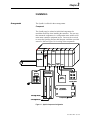
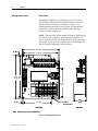
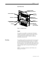
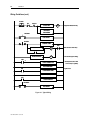
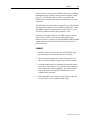
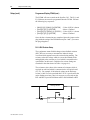
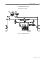
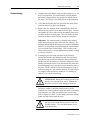
SyncPro™
Bulletin 1901
Installation Manual
www.abpowerflex.com
Important User Information
Read this document and the documents listed in the Additional Resources section about installation, configuration, and
operation of this equipment before you install, configure, operate, or maintain this product. Users are required to
familiarize themselves with installation and wiring instructions in addition to requirements of all applicable codes, laws,
and standards.
Activities including installation, adjustments, putting into service, use, assembly, disassembly, and maintenance are required
to be carried out by suitably trained personnel in accordance with applicable code of practice.
If this equipment is used in a manner not specified by the manufacturer, the protection provided by the equipment may be
impaired.
In no event will Rockwell Automation, Inc. be responsible or liable for indirect or consequential damages resulting from the
use or application of this equipment.
The examples and diagrams in this manual are included solely for illustrative purposes. Because of the many variables and
requirements associated with any particular installation, Rockwell Automation, Inc. cannot assume responsibility or
liability for actual use based on the examples and diagrams.
No patent liability is assumed by Rockwell Automation, Inc. with respect to use of information, circuits, equipment, or
software described in this manual.
Reproduction of the contents of this manual, in whole or in part, without written permission of Rockwell Automation,
Inc., is prohibited.
Throughout this manual, when necessary, we use notes to make you aware of safety considerations.
WARNING: Identifies information about practices or circumstances that can cause an explosion in a hazardous environment,
which may lead to personal injury or death, property damage, or economic loss.
ATTENTION: Identifies information about practices or circumstances that can lead to personal injury or death, property
damage, or economic loss. Attentions help you identify a hazard, avoid a hazard, and recognize the consequence.
IMPORTANT
Identifies information that is critical for successful application and understanding of the product.
Labels may also be on or inside the equipment to provide specific precautions.
SHOCK HAZARD: Labels may be on or inside the equipment, for example, a drive or motor, to alert people that dangerous
voltage may be present.
BURN HAZARD: Labels may be on or inside the equipment, for example, a drive or motor, to alert people that surfaces may
reach dangerous temperatures.
ARC FLASH HAZARD: Labels may be on or inside the equipment, for example, a motor control center, to alert people to
potential Arc Flash. Arc Flash will cause severe injury or death. Wear proper Personal Protective Equipment (PPE). Follow ALL
Regulatory requirements for safe work practices and for Personal Protective Equipment (PPE).
Allen-Bradley, Rockwell Software, Rockwell Automation, and TechConnect are trademarks of Rockwell Automation, Inc.
Trademarks not belonging to Rockwell Automation are property of their respective companies.
Table Of Contents
Product Description
Chapter 1
Description ............................................................................................. 1-1
Documentation ....................................................................................... 1-1
Synchronous Motor Theory ................................................................... 1-2
Protection Features ................................................................................. 1-3
Theory of Operation ...................................................................... 1-3
Optional Equipment ........................................................................ 1-4
Display/Metering Features ..................................................................... 1-4
Hardware ................................................................................................ 1-5
Typical Synchronous Starter Components .............................................. 1-5
Motor Contactor ............................................................................... 1-5
Motor Contactor Pilot Relay ............................................................ 1-5
Field Voltage Relay .......................................................................... 1-6
Equipment Shutdown Relay ............................................................. 1-6
Phase Angle Transducer .................................................................. 1-6
Discharge Resistor ........................................................................... 1-7
Field Contactor ................................................................................. 1-7
Resistors RF1 and RF2 ..................................................................... 1-7
Analog/Digital Pulse Board .............................................................. 1-7
Input/Output Descriptive Listing ............................................................. 1-8
Control .............................................................................................. 1-8
Field Application ............................................................................... 1-9
Feedback .......................................................................................... 1-9
Fault Detection ............................................................................... 1-10
Status .............................................................................................. 1-11
Specifications ........................................................................................ 1-11
General Specifications ................................................................. 1-11
Specific Specifications ................................................................. 1-12
DTAM Specifications .................................................................. 1-12
Receiving and Storage
Chapter 2
Receiving ............................................................................................... 2-1
Storage ................................................................................................... 2-1
Installation
Chapter 3
Arrangements ......................................................................................... 3-1
Component ...................................................................................... 3-1
Open Frame ..................................................................................... 3-2
Integral ............................................................................................ 3-3
Grounding .............................................................................................. 3-3
Wiring Guidelines .................................................................................... 3-4
Summary .................................................................................................. 3-7
1901-UM020C-EN-P –June 2013
ii
Table of Contents – SyncPro™ Instruction Manual
Setup and Commissioning
Chapter 4
Setup .....................................................................................................
Lithium Battery ...............................................................................
Analog Card DIP Switches .............................................................
Programmer/Display DTAM ..........................................................
RF1 and RF2 Resistor Setup ............................................................
Commissioning ......................................................................................
Programming the SyncPro
Chapter 5
Set Points ...............................................................................................
Set Point 1 • Minimum % Synchronous Slip Frequency .................
Set Point 2 • Power Factor Trip ......................................................
Set Point 3 • Power Factor Trip Time Delay ..................................
Set Point 4 • Squirrel-Cage Protection Trip Time (at 95% speed) ....
Set Point 5 • Squirrel-Cage Protection Trip Time (at 50% speed) ....
Set Point 6 • Squirrel-Cage Protection Trip Time (at stall) ............
Set Point 7 • Function Number .......................................................
Set Point 8 • Incomplete Sequence Trip Time Delay ......................
Set Point 9 • Diagnostic Fault Mask ...............................................
Additional Parameters............................................................................
Monitoring
5-1
5-2
5-2
5-2
5-3
5-3
5-3
5-4
5-5
5-5
5-6
Chapter 6
Power Factor..........................................................................................
Faults .....................................................................................................
Fault Detection and Diagnostics ......................................................
Power Factor Circuit Fault .............................................................
Troubleshooting
4-1
4-1
4-1
4-1
4-2
4-7
6-1
6-1
6-1
6-2
Chapter 7
Last Trip Codes • Table 7.A .................................................................. 7-1
Troubleshooting Guide • Table 7.B ....................................................... 7-2
Spare Parts
Chapter 8
Spare Parts List for SyncPro ................................................................. 8-1
1901-UM020C-EN-P –June 2013
Chapter
1
Product Description
Description
The SyncPro consists of a programmable small logic controller
(SLC 500) with the following additional peripheral items:
•
•
•
•
•
Data Table Access Module (DTAM)
Power Factor Transducer
Analog/Digital Pulse Board
Conditioning Resistors
Interposing Relays FCR and ESR
The SyncPro system is designed to provide supervisory protection
and field control to a brush-type synchronous motor controller,
proper field application timing, squirrel-cage protection against
long acceleration and stall conditions as well as running pullout
protection by monitoring motor power factor. When combined
with a suitable induction motor protection relay, the SyncPro
provides the necessary overload protection to the brush-type
synchronous motor.
Important: Although the SyncPro makes use of some standard
SLC 500 programmable controller components, it is imperative
that the controller is a dedicated unit expressly for the control and
protection of the field of a single synchronous motor. The
firmware and hardware configuration must only be used for its
designed purpose. Do not attempt to modify the controller in any
way for another use. No additional SLC control cards can be
added.
Documentation
The following publications have pertinent information for
components used in or associated with the SyncPro:
1747-ND013
1747-NI002
1746-NM003
1900-2.10
900-1.0
SGI-1.1
1746-2.35
1746-2.36
Data Table Access Module – User Manual
SLC500 Modular Hardware Style – Installation
and Operation Manual
Analog Card publication
Measuring for Synchronous Motor Data
Synchronous Motor Control
Safety Guidelines for the Application,
Installation and Maintenance
Discrete Input and Output Modules
SLC500 Modular Chassis and Power Supplies.
1901-UM020C-EN-P – June 2013
1-2
Product Description
Synchronous Motor Theory
The synchronous motor is a commonly used industrial motor
favored for its higher efficiency, superior power factor, and low
inrush currents. Typical applications that benefit from the constant
operating speed include refiners, head box fan pumps, chippers,
etc. Synchronous motors are particularly well suited to low RPM
applications. The synchronous brush-type motor is composed of
a three-phase stator winding, a DC rotor winding, and a squirrelcage winding.
The stator winding is identical to that of an induction motor and, as
such, the direction of motor rotation depends on the rotation of the
stator flux. The direction can be changed by reversing two of the
stator leads, just as it does with induction motors.
The rotor contains laminated poles which carry the DC field coils
that are terminated at the slip rings. It also has a squirrel-cage
winding composed of bars embedded in the pole faces and shorted
by end rings. The squirrel-cage winding is also known as
“damper” or “amortisseur” winding. This winding enables the
motor to accelerate to near synchronous speed so that the DC
supply can be applied to the field windings for synchronizing the
motor to the line (typically 95%).
These field windings are connected through slip rings to a discharge
resistor during start up. The resistor is required to dissipate the
high voltages that are induced into the field windings from the
stator, and it is removed from the circuit when the DC field voltage
is applied. The synchronous motor can be compared to a transformer,
with the three-phase stator resembling the primary and the field
winding acting like a secondary. Through this transformer action,
an induced voltage is generated in the motor field during starting.
The induced signal can be used to protect the squirrel-cage winding
by monitoring the motor speed during acceleration and to
determine when the DC field can be excited for synchronization.
At zero speed, the frequency induced into the field is 60 Hz, at
95% speed the frequency induced is 3 Hz (for a 60 Hz system).
Once at 95% speed, the DC field is supplied with either 125 V DC
or 250 V DC and the discharge resistor is removed from the circuit.
The excitation in the field windings creates north and south poles
in the rotor which lock into the rotating magnetic field of the
stator. The slip rings are used to connect the field windings to the
discharge resistor and static exciter. It is at these slip rings that the
field resistance of the motor can be measured to confirm the required
field voltage and current at rated power factor. If, for example, the
field voltage is 125 V DC and the current is 20 amps DC, then the
resistance measured should be about 6 ohms, based on Ohms Law.
1901-UM020C-EN-P – June 2013
Product Description
Protection Features
1-3
Theory of Operation
When the NOT STOP and START signals go high, a timer is
started (refer to Figure 7.1). The START signal must be dropped
before another start can be initiated. The timer is preset based on
the slip frequency of the motor. If the timer expires prior to achieving
the maximum asynchronous speed, the starting sequence will halt,
the TRIP output will be dropped and the DTAM will display a
message indicating the faulted condition. The TRIP signal is restored
when there are no faults and the Fault Reset PB input is received.
NOTE: The NOT STOP and START can be tied together to
indicate a RUN condition to control the device without separate
signals. The RUN output follows the start input if the motor is
permitted to start, (i.e. no faults and the EQUIPMENT
SHUTDOWN is high).
If the programmed percentage of synchronous speed is obtained
within set time limits (refer to programming of set point, Chapter 5),
the FIELD RELAY is energized. The power factor is now monitored
and displayed on the DTAM. If the power factor drops below the
programmed values, the TRIP and FIELD RELAY outputs will be
dropped and the DTAM will display a message indicating the
faulted condition. Under normal conditions the FIELD RELAY is
maintained until the NOT STOP signal is removed.
The slip frequency is calculated from a square wave input representing the slip frequency. Based on this frequency, the allowable
starting time is calculated. This calculation is based on three set
points which are entered by the user, as well as a ‘function order’
used to shape the curve. The three required set points are:
• maximum allowable starting times at the stalled condition
• 50% speed
• maximum programmed percentage of synchronous speed
The time curve between stalled frequency and 50% speed is
assumed to be linear. The time between 50% speed and the
synchronizing speed is to the nth order such that unity makes it
linear, 2-5 makes it exponential in nature. The higher the order,
the shorter the times near to 50% speed and the higher the times
near the synchronous speed set point (i.e. bottom of curve (time vs.
frequency) is flatter and then rises more steeply).
NOTE: If the time set point at the maximum programmed
percentage of synchronous speed is set below that of the extended
stall (i.e. 50% speed curve), the function between 50% speed and
synchronous speed will also be treated as linear. (For example, the
slope between 50% speed and synchronizing speed is flatter than
the slope between stalled and 50% speed).
1901-UM020C-EN-P – June 2013
1-4
Product Description
Protection Features (cont.)
When the maximum programmed percentage of synchronous speed
(set point) is obtained, the field coil is energized on the falling
pulse of the negative square wave (i.e. a rising sinusoid) from the
slip frequency generator. A fixed time period after synchronization,
the autoload signal is raised. The field coil is energized only if the
TRANSITION COMPLETE has been received.
• Squirrel-Cage Winding Protection – Protects the squirrel-cage
winding from long acceleration and stall conditions during starting.
• Field Winding Application Control – The signal that triggers
application of the field excitation when the programmed
asynchronous speed is obtained.
• Incomplete Sequence Timing Relay – Trips the system if the
overall starting time is exceeded.
• Pull Out Protection – Monitors the power factor during running
to detect a loss of synchronism.
• Field Voltage Failure Relay Input – Monitors the condition of
the static exciter output. This relay must be supplied by the
customer if the SyncPro is not supplied as a configured unit within
a Rockwell Automation/Allen-Bradley motor controller.
Optional Equipment
• Field Current Failure Relay
• Load and Unload Auxiliary Contacts – The outputs are energized
2 sec. after the field is applied and is maintained until the field is
removed.
Display/Metering Features
The product in conjunction with the Data Terminal Access Module
(DTAM) will perform the following metering/display functions:
•
•
•
•
display all detected fault conditions
display the slip frequency and starting time during startup
display the power factor during run mode.
accept set points through the DTAM for the following:
– maximum % asynchronous speed [% of synchronous speed]
– power factor set point and trip delay
– maximum allowable time at stalled state (maximum slip)
– maximum allowable time at 50% speed
– maximum allowable time at synchronizing speed (typically @
95% speed)
– function order (allows adjustment of the slope of the
acceleration/stall time trip curve).
– incomplete sequence timer trip delay
– fault mask for PF transducer diagnostics
(Refer to Chapter 5 for complete details.)
1901-UM020C-EN-P – June 2013
Product Description
Hardware
1-5
The system consists of the following hardware:
•
•
•
•
•
•
•
•
•
•
•
•
•
•
SyncPro
1747-L532
1746-ITB16
1746-NIO4I
1746-0X8
1746-IA16
1746-A7
1746-P1
1747-DTAM
700-F220A1
80165-998-51
80025-817-01
80165-778-51
800T-PB16R
5/03 Processor :
EEPROM
High Speed DC Input Module
Analog Input/Output Module
Isolated Relay Output (or any 8-point output)
120VAC Input Module (or any 16-point input)
7-Slot Rack
Power Supply
Data Table Access Module
Interposing Relay (FCR, ESR)
Phase Angle Transducer
20 kilohm Tapped Conditioning Resistors
Analog/Digital Pulse Board
Red Illuminated Push Button
: Contains specialized patented hardware for synchronous application on EEPROM
that cannot be viewed/accessed.
Typical Synchronous Starter
Components
The following list of components are devices which the SyncPro is
connected to, or are part of the SyncPro protection package.
Motor Contactor (M)
The motor contactor is used to provide and switch the power
supplied to the motor stator. It is controlled by the SyncPro
package and is necessary to remove stator power in the event of a
stop command or a trip condition. Two normally open contactor
auxiliaries may be required; one mandatory N.O. contact to give
contactor status information to the SyncPro, and one may be
needed as a hold-in contact for the main control circuit.
Motor Contactor Pilot Relay (CR1 or MR)
This interposing relay allows the SyncPro output to pick up the
main contactor coil. The power requirements of the pick-up coils
used in most medium voltage motor starters would exceed the
switching capability of the 1746-OX8 output contact.
1901-UM020C-EN-P – June 2013
1-6
Product Description
Typical Synchronous Starter
Components (cont.)
Field Voltage Relay (FVR)
When energized, this DC relay indicates that the DC exciter supply
is healthy and producing an adequate level of DC excitation. The
field voltage relay is required to prevent starting the motor unless
DC excitation is available. A field voltage relay is recommended
as the SyncPro does not have the ability to determine the level of
the exciter output voltage. It is needed to prevent unnecessary
starts when synchronization cannot occur.
Equipment Shutdown Relay (ESR) (Component included with
SyncPro)
The ESR relay combines the status of customer supplied protective
and interlock devices to a single contact input on the SyncPro.
When ESR is energized, it is an indication that all external trip
and interlock contacts to the SyncPro are in a "not tripped"
condition. All external trips and interlocks must be wired in series
with the ESR coil in order to be properly addressed by the
SyncPro.
Phase Angle Transducer (Component included with SyncPro)
The phase angle transducer provides a conditioned 4- to 20milliamp signal to the analog module of the SyncPro system. The
transducer is factory calibrated to provide a specific output at zero
(0) lagging power factor, at 1.0 or unity power factor, and at zero
(0) leading power factor. These factory settings must not be
altered.
The SyncPro processor scales and interprets this signal to compare
it to the power factor trip set point and to cause a trip to occur if
the power factor drops below the programmed value for more than
the specified power factor trip time delay. If the DC excitation is
lost, a low voltage condition exists, or the motor is being
overloaded to a point where the motor can no longer maintain
synchronous speed, the motor power factor will react by dropping
to a very lagging value. This indicates that the motor is slipping
poles and the controller should be shut down to protect the motor.
The phase angle transducer monitors voltage across lines 1 and 2,
along with the current in line 3 to obtain a power factor reading.
When the reading is below the set points programmed, the SyncPro
will shut down the starter.
1901-UM020C-EN-P – June 2013
Product Description
1-7
Discharge Resistor
The discharge resistor is specified by the motor manufacturer for a
specific application to obtain correct starting and pull in torques and
to provide a means of discharging the motor induced field voltage
when starting and stopping the motor. The field winding has more
turns than the stator winding and when power is applied to the
stator, the field acts like the secondary windings of a current
transformer. A field winding without a discharge path will
produce a voltage greater than its insulation rating, and as such,
requires a means to discharge or limit the voltage. If the discharge
resistor is not connected during a start, the induced voltage can
build to a point where the field winding insulation can be
damaged. The resistor is also used to provide reference points to
the SyncPro synchronous motor protector (refer to Chapter 4).
Field Contactor (FC)
The field contactor provides two normally open and one normally
closed power poles. The normally open contacts apply DC power
to the motor field windings when the contactor is energized. Prior
to energization and after de-energization, the normally closed pole
makes the path to the discharge resistor to allow the dissipation of
energy induced in the field during starting. It also provides a path
to discharge the stored energy in the large inductive motor field
winding on stopping of the motor.
Resistors RF1 and RF2
These resistors are used to attenuate the voltage which reaches the
analog/digital pulse board. Set up of these resistors is important
because if the signal voltage to the board is too low (too much
resistance) then pulses will not be produced. If too little resistance
is used, the voltage may be too high which could damage the
analog/digital pulse board. Refer to Chapter 4, page 4-2.
Analog/Digital Pulse Board
This board converts the voltage sinusoidal waveform across the
discharge resistor and, by examining the zero crossings, creates a
digital pulse train of an equal frequency to the induced slip
frequency occurring in the discharge resistor. At start (zero speed),
the frequency will be 60 Hz, at 95% speed, the frequency will be 3
Hz (for a 60 Hz system). This feedback is used by the SyncPro to
determine the speed of the motor at any time during acceleration
and when the motor has reached the desired speed set point to
synchronize.
1901-UM020C-EN-P – June 2013
1-8
Product Description
Input/Output Descriptive
Listing
Control
NOT STOP (I:4/00)
This signal must be maintained high for the SyncPro to operate.
When the signal is taken low, the software identifies this as a normal
stop for the motor.
Important: The SyncPro does NOT have control over stopping
the motor. The main portion of the motor controller performs this
control function.
The NOT STOP signal must be given in parallel to that of the
hardware, i.e. from the same PLC output or push button.
START INPUT(I:4/01)
The rising edge of this signal starts the operation of the SyncPro.
This signal is maintained high for two-wire control or may be
dropped after initial starting if three-wire control is used. In both
cases, this signal controls the START output. After a fault has
occurred, this input must be taken low before another start
command will be recognized.
RUN OUTPUT(O:3/06)
This output is used to control motor starting. It is the START
input conditioned by all permissives. That is to say that this output
will follow the state of the input as long as all permissives are met.
Thus in two-wire control, this output is actually a RUN command
and will stay high until either a fault occurs or a stop is issued. In
three-wire control the output is maintained only as long as the input
is maintained, a fault occurs, or a stop is issued.
EQUIPMENT SHUTDOWN RELAY (ESR) INPUT (I:4/07)
This fault input is used to group all external faults. It notifies the
SyncPro that the system has stopped for an external reason. The
SyncPro will send a message indicating the reason for the stoppage.
In the normal state this signal is held high, going low on a fault
condition. While this signal is low, a start signal will not be accepted.
Typically, all emergency stops or external faults (i.e. overloads,
motor protection relays) will be wired to an ESR relay. This relay
is then fed into the SyncPro for logging and control and also tied
into the hardware to stop the motor.
TRIP (O:3/01)
This output is high during normal conditions. When the SyncPro
detects a fault, the output goes low and the SyncPro stops the
motor. The trip output is typically wired into the ESR circuit. It
will be set high when there are no faults and the FAULT RESET
PB is momentarily raised high.
1901-UM020C-EN-P – June 2013
Product Description
1-9
Field Application
TRANSITION COMPLETE CONTACT (I:4/06)
(OPTIONAL)
The field relay output will not be energized until this input
permissive is given. Once the field relay is picked up, this
permissive is no longer required. If the permissive is not given
prior to the squirrel-cage protection timing out or the incomplete
sequence timing out, the SyncPro will fault and stop the motor.
If unused, it must be tied high. This input is intended for an
external input such as the RUN contact of an autotransformer
starter. It prevents synchronization until the autotransformer
starter has first transitioned to full voltage RUN mode.
FIELD RELAY (O:3/00)
This output controls the field contactor relay which applies the
field to the motor. This output is energized when the transition
complete permissive is given and the synchronous setpoint has
been reached. The field is then applied either on the rising
waveform or after a fixed time period of one second if the motor
synchronizes on reluctance torque. The output is dropped whenever
the NOT STOP is removed, the EQUIPMENT SHUTDOWN
RELAY is removed, or a fault is detected.
Feedback
MOTOR CONTACTOR FEEDBACK CONTACT (I:4/08)
This input indicates to the SyncPro that the motor contactor is
closed, confirming that the motor is running. It also allows the
SyncPro to detect a fault in the contactor circuit.
FIELD CONTACTOR FEEDBACK CONTACT (I:4/05)
This input indicates to the SyncPro that the field contactor has
picked up, confirming that the field has been applied. (The signal
must come from the auxiliary of the coil which ultimately applies
the field, i.e. contactor.) If missing, the SyncPro detects a fault in
the field circuit.
TRIP/RESET PB INPUT (I:4/02)
This input from the push button on the panel will reset any fault
condition in the SyncPro. Once no fault exists, the fault condition
will be removed from the DTAM and the TRIP output will be set.
1901-UM020C-EN-P – June 2013
1-10
Product Description
Input/Output Descriptive
Listing (cont.)
Fault Detection
FIELD VOLTAGE RELAY INPUT (I:4/03)
When the signal is low, it indicates a lack of field voltage. This
input is monitored for a fault condition only while starting, prior to
applying the field. Tie this input high if it is not used. When this
contact is high, it verifies that the static exciter is providing an
appropriate DC voltage.
FIELD CURRENT RELAY INPUT (I:4/04) (OPTIONAL)
When the signal is low, it indicates a lack of field current. This
input is monitored for a fault condition after the field has been
applied. Tie this input high if it is not used. This optional input
verifies there is DC current flowing from the static exciter to the
motor field. It is redundant since the power factor trip feature will
trip if the field current is lost.
POWER FACTOR (I:2/0)
The signal supplied to the SyncPro is from the Phase Angle
Transducer, representing a power factor of zero (0) lagging to zero
(0) leading respectively. Note that the SyncPro firmware has been
tailored to this specific transducer. No substitution is allowed.
SLIP GENERATOR POWER (I:1/01)
This fault input is monitored during idle and starting periods. It is
normally held high by the power supply to the Slip Pulse
Generator.
SLIP GENERATOR NEGATIVE (-) (I:1/00)
Connect to the negative terminal (N) of the Slip Pulse Generator.
SLIP GENERATOR POSITIVE (+) (I:1/02)
Connect to the positive terminal (P) of the Slip Pulse Generator.
1901-UM020C-EN-P – June 2013
Product Description
1-11
Status
AUTO LOAD (O:3/07)
Output is energized two seconds after the field is applied and
remains closed until the field is removed from the motor by a stop
or a fault.
SCP TRIP (O:3/02)
Output is set high when a Squirrel-Cage Protection Fault occurs.
It is reset when the TRIP output goes high after pushing the reset
button. This signal can be used for indication, via a pilot light, or
it can be used as an optional trip output.
MOTOR PULLOUT TRIP (O:3/03)
Output is set high when the power factor lags for longer than the
programmed trip time delay indicating that the motor has pulled
out. It is reset when the TRIP output goes high after pushing the
reset button. This signal can be used for indication, via a pilot
light, or it can be used as an optional trip output.
INCOMPLETE SEQUENCE TRIP (O:3/04)
Output is set high when an Incomplete Start Sequence Fault occurs.
It is reset when the TRIP output goes high. This signal can be used
for indication, via a pilot light, or it can be used as an optional trip
output.
Specifications
General Specifications
Operating Power
Input Line Voltage – 120 Volts AC 50/60 Hz
Input Current – 0-5 Amps.
Temperature and Humidity
Temperature
(Maximum Ambient)
Humidity
Operating
0°C to 40°C (32°F to 104°F)
Storage
-20°C to 65°C (-4°F to 149°F)
5 to 95% (non-condensing)
Maximum Temp.: 35°C (95°F)
1901-UM020C-EN-P – June 2013
1-12
Product Description
Specifications (cont.)
Specific Specifications (for Phase Angle Transducer)
General
Accuracy:
Housing:
Weight:
3% span
Flame retardant plastic case
2.4 kg maximum
Climate
Storage:
Temp. range:
Humidity:
-20 to 70°C (-4 to 158°F)
-20 to 70°C (-4 to 158°F) storage
Operational @ 0 to 60°C (32 to 140°F)
Calibrated @ 23°C (73°F)
Up to 95% RH. Non-condensing
Input
Frequency:
Current:
Range (A):
Burden:
Voltage:
Range (V):
50 or 60 Hz
Any value between 0.2 and 10 A
20 - 120%
5 VA Maximum
Between 115V/230V ±10%
± 20 % (20 - 120% with sep. aux.)
Burden 1 VA maximum
Overload Capacity
Six times rated current for 30 seconds
1.25 rated voltage for 10 seconds
Electrical Tests
Dielectric Test:
Impulse Test:
Surge Withstand:
Certification:
2kV RMS to BS 5458
5kV transient as BEAMA 219 & BS923
ANSI C37-90A
CSA Approved
DTAM Specifications
Refer to Publication 1747-NC013, Appendix A-1, A-2.
SLC500 Specifications
Refer to Publication 1747-NI002, SHT 1-4
Power Supply Specifications
Refer to Publication 1747-NI002, SHT 1-7
1901-UM020C-EN-P – June 2013
Chapter
2
Receiving and Storage
Receiving
Upon receiving the controller, remove the packing and check for
damage that may have occurred during shipping. Report any
damage immediately to the claims office of the carrier.
NOTE: If the SyncPro is an integral component of a brush-type
synchronous starter (Bulletin 1912B), special receiving and
handling instructions will apply. For details, refer to the service
manual provided with the equipment.
Storage
It is important to consider the following storage requirements if
you are not installing your controller immediately after receiving it.
• Store the controller in a clean, dry, dust-free environment.
• Storage temperature should be maintained between -20°C and
70°C (-4°F and 158°F).
• Relative humidity must not exceed 95%, non-condensing.
1901-UM020C-EN-P – June 2013
2-2
Receiving and Storage
1901-UM020C-EN-P – June 2013
Chapter
3
Installation
Arrangements
The SyncPro is offered in three arrangements.
Component
The SyncPro may be ordered as individual components for
maximum flexibility when installing the controller. The user may
then mount the components in a configuration most suitable to his
main motor controller equipment layout. Care must be exercised
to ensure the SyncPro processor has adequate ventilation provided
around it. Refer to Figure 3.6 for wiring of the components.
SLC 5/03
CPU
INPUT
OUTPUT
INPUT
OUTPUT
INPUT
SyncPro
˜
FAST
DC SINK
DTAM
ANALOG
ISOLATED
RELAY
115 VAC
Controls &
Indicators
Analog/Digital
Pulse Converter
Relays
(FCR, etc.)
To Discharge Resistor
Resistor (RF)
Resistor (RF)
To Control Power
Analog/Digital
Pulse Converter
To CT (Phase A)
To Discharge Resistor
Figure 3.1 – SyncPro Component Configuration
1901-UM020C-EN-P – June 2013
Installation
3-2
Arrangements (cont.)
Open Frame
The SyncPro components are mounted on a panel, except the
DTAM display module and the illuminated push button for trip
indication and reset function. See Figures 3.2 and 3.3 for
mounting dimensions of the main unit panel, DTAM and 800T
push button. Quick installation within the main controller is
possible with this arrangement.
NOTE: The Data Table Access Module (DTAM) is supplied with a
two-meter cord for connection with the SyncPro processor. Be
sure to mount the DTAM in a suitable location for this connection
to be made. If a longer cord is required, refer to Publication 1747ND013 to find the appropriate catalog number.
18.02 [458]
.38 [10]
16.75 [425]
20.00 18.95
[508] [481]
13.29
[338]
.63 [16]
13.75 [349]
Front View
Note: Dimensions are in inches [millimeters].
Figure 3.2 – Mounting Dimensions
1901-UM020C-EN-P – June 2013
.36 [9] dia.
(4) Mounting Holes
6.12
[155]
Side View
Installation
3-3
Open Frame (cont.)
Analog/Digital
Pulse Converter Board
Fusible Terminal Blocks
Conditioning
Resistors, RF
Terminal Blocks
FCR Relay
(DIN Rail Mounted)
ESR Relay
(DIN Rail Mounted)
Phase Angle Transducer
(DIN Rail Mounted)
Bulletin 1746
7-slot Card Rack
with P1 Power Supply
Ground Bar
Figure 3.3 – Component Layout
Integral
The SyncPro is also available as a component of a Rockwell
Automation/Allen-Bradley synchronous motor starter (Bulletin
1912B) incorporating the components shown in Figure 3.3.
Although the layout in the starter is different, control and
functionality remain the same.
Grounding
The grounding required by the SyncPro panel has been brought to
a common grounding bar mounted on the panel. It is important
that once the unit is installed, that this grounding bar is wired to
the starter ground bus. It is important that a proper ground is made
as the SyncPro has a number of low voltage signals which, if not
properly grounded, may be vulnerable to noise causing erratic
operation.
NOTE: For grounding requirements of the DTAM, refer to
Publication 1747-NC013.
1901-UM020C-EN-P – June 2013
3-4
Installation
Wiring Guidelines
The SyncPro™ can accept either two- or three-wire control. The
control chosen will determine the configuration of the control
hardware. Consider the following two inputs and single output
when selecting the type of control:
• I:4/00
• I:4/01
• O:3/06
NOT STOP input
START input
RUN output
If using two-wire control, the two inputs (I:4/00 and I:4/01) are
tied together. They are both low in order to stop the SyncPro (refer
to the summary on page 3-6) and both high in order to run the
device. To start the device after a fault, the START input (I:4/01)
must be taken low and then closed again. In this configuration, the
RUN output acts as a run command. Refer to Figure 3.4.
If using three-wire control, the NOT STOP input must be
maintained high in order to run the device. Momentarily opening
this input will cause the SyncPro to stop (refer to the summary on
page 3-6). Momentarily closing the START input will start the
SyncPro (given that all permissives are satisfied). In this
configuration, the RUN output acts as a start command. Refer to
Figure 3.5.
RUN
OFF
Run Control
Circuit
I:4/00 NOT STOP
I:4/01 START
Emergency
Shutdown
Circuit
ESR
E-STOP
O/L
O:3/06 RUN
CR
O:3/01 TRIP
ESR
External
I:4/07 EQUIP.
SHUTDOWN
Figure 3.4 – Two-Wire Control
1901-UM020C-EN-P – June 2013
Installation
3-5
In both cases, the RUN output will follow the state of the START
input, provided that all starting conditions are met. Note that in all
cases, stopping the motor is done via the hardwired control circuit
logic, and notification only is given to the SyncPro™.
Figure 3.4 shows a typical two-wire control circuit. The selector
switch is used to control the NOT STOP and the START as a pair.
It is also used to ensure the motor is stopped via the hardwired
control circuit logic, (even though in this case the RUN output will
be removed when the selector switch is turned off).
The ESR circuit ensures the motor is stopped for any fault condition
occurring either externally or when detected by the SyncPro. Once
the ESR has dropped out (detected by the loss of I:4/07), the
selector switch must be switched off and on to initiate a start. This
prevents a premature start if the fault condition is cleared and the
selector switch is still in the run position.
Figure 3.5 shows a typical three-wire control circuit. The STOP
PB must be maintained high in order to initiate a start and to run
the system. The button also ensures that the motor is stopped via
the hardware circuit. The momentary START PB is used to create
a RUN (START) output signal of the same duration as the input
signal as long as there are no faults detected by the SyncPro.
START PB
I:4/01 START
STOP PB
I:4/00 NOT STOP
ESR
O:3/06 RUN
CR
CR
E-STOP
O/L
External
ESR
O:3/01 TRIP
I:4/07 EQUIP
SHUTDOWN
Figure 3.5 – Three-Wire Control
1901-UM020C-EN-P – June 2013
3-6
Installation
Wiring Guidelines (cont.)
E-STOP
O/L
External
O:3/01 TRIP
ESR
Equipment Shutdown Relay
I:4/07 EQUIP
SHUTDOWN
PB START
I:4/01 START
PB STOP
I:4/00 NOT STOP
ESR
O:3/06 RUN
CR
Main Contactor Pilot Relay
FCR
Field Coil Relay (Pilot Relay)
CR
O:3/00 FIELD RLY
FCR
*
I:4/05 FLD CONT AUX
* Auxiliary Contact from final
coil in chain (if acceptable)
I:4/06 TRANS CMP
Eg. Not Used
MC
I:4/08 M CONT FDBK
I:4/04 FLD CURRENT RLY
FVR
I:4/03 FVR RELAY
PB RESET
I:4/02 RESET
Figure 3.6 – Typical Wiring
1901-UM020C-EN-P – June 2013
Installation
3-7
In this case (three-wire) since the START signal is only momentary,
the hardware must perform the sealing function using the control
relay, CR. The START output is really an extension of the
START input, except that the output is conditioned by any fault
conditions.
The ESR circuit ensures the motor is stopped for any fault condition
occurring either externally or when detected by the SyncPro. Once
the ESR has dropped out (detected by the loss of I:4/07), a start
will not be permitted until the fault condition is reset.
It should be noted that in all cases, the TRIP output is removed
when a fault is detected. This fault includes both external
hardware faults (as recognized by the EQUIPMENT SHUTDOWN
signal) and faults which are generated by the SyncPro such as a
power factor trip.
SUMMARY
1. The RUN output will follow the state of the START input,
given that there are no faults detected by the SyncPro.
2. Once a fault has been detected, the START input must be
taken low before the RUN output will be allowed to operate.
3. All motor stopping must be controlled by hardwired control
circuit logic. The SyncPro is only notified of the stoppage in
order to determine what is happening. Any time the motor
stops without first removing NOT STOP input, an error
condition will be detected.
4. When using three-wire control, a contact from the CR relay
must be used to seal in around the RUN output.
1901-UM020C-EN-P – June 2013
3-8
Installation
○
○
○
○
○
○
○
○
○
○
○
○
○
○
○
○
○
○
○
○
○
○
○
○
○
○
○
○
○
○
○
○
○
○
○
Wiring Guidelines (cont.)
○
○
Figure 3.7 – Typical Wiring Diagram (3-wire Control)
1901-UM020C-EN-P – June 2013
Chapter
4
Set up and Commissioning
Setup
Check the following components of the SyncPro once it has been
installed.
Lithium Battery
Ensure the supplied lithium battery is connected. This battery
maintains power to the processor, preserving programmed set
points loaded into RAM memory through the DTAM. To verify
the connection, remove the processor in slot 0 of the I/O rack. The
battery is on the printed circuit board with wires extending from it
to a keyed connector. The connector must be plugged into the
matching keyed receptacle.
Analog Card DIP switches
Remove the analog card from slot 1 of the I/O rack and verify that
the DIP switches on the side of the printed circuit board have both
been set to the ‘ON’ position. For further details, refer to the
analog card publication number 1746-NIO4I. These are normally
set at the factory.
Programmer/Display DTAM
Prior to usage the DTAM must be configured as follows while
connected to a functional SyncPro 5/03 with the Synchronous
Protector program. Refer to the DTAM manual 1747-ND013 for
more detailed information on the procedure. This setup procedure has
been performed in the factory, but in case of difficulty, the following
procedure may be used. Ensure the jumper in the back of the DTAM
is connected between pins 1 and 2 to enable the MODIFY mode.
•
•
•
•
•
•
•
•
•
•
Apply power to the SyncPro controller.
On the DTAM, press the [7] and [INC] keys simultaneously
until the Modify Setup Screen is obtained.
Press [ENTER] (for Confirmation)
Press [ENTER] (for English)
Press the [INC] or [DEC] keys to show the number 2, press
[ENTER] (for DTAM address)
Press the [INC] or [DEC] keys to show 19200, press [ENTER]
(for the Baud Rate)
Press the [INC] key to show ON, press [ENTER] (for auto attach)
Press the [INC] key to show ON, press [ENTER] (for
Backlighting)
Press the [INC] key to show ON, press [ENTER] (for Monitor
Override)
Press [ENTER] (to accept the setup).
1901-UM020C-EN-P – June 2013
4-2
Setup and Commissioning
Setup (cont.)
Programmer/Display DTAM (cont.)
The DTAM will now re-attach to the SyncPro 5/03. The F()-1 and
F()-2 Macros must now be programmed into the DTAM. Perform
the following key sequences:
•
•
•
•
[Shift][N][2][3][Shift][:][0][ENTER]
[Shift][F()][F()][1][ENTER]
[Shift][N][2][3][Shift][:][1][ENTER]
[Shift][F()][F()][2][ENTER]
– Value of N23:0 is shown
– Macro 1 Defined
– Value of N23:1 is shown
– Macro 2 Defined
Once the above instructions are completed, place the jumper on the
plug inside the casing of the DTAM between pins 1 and 3, (or remove
the plug altogether).
RF1 & RF2 Resistor Setup
The synchronous motor field discharge resistor feedback resistors
(RF1, RF2) are necessary to attenuate the induced voltage
waveform which appears across the resistor during starting. The
resistors reduce the voltage which is seen at the terminals of the
analog/digital pulse converter to a level which is acceptable to the
optoisolators on the board. Guidelines for resistor settings are
contained in the chart shown in Table 4.A (page 4-6).
The resistance value shown is the amount of resistance which is
required on each lead which is connected to the A/D pulse board
(F1, F2). For example, if the induced voltage on the discharge
resistor is 1000 V at zero speed and 600 V at 95 % speed (across the
entire discharge resistor), then it is necessary to select taps on the
RF1 and RF2 to provide 20 kilohms at RF1 and 20 kilohms at RF2.
Discharge Resistor
RF
RF
F1
20 kΩ
1901-UM020C-EN-P – June 2013
F2
20 kΩ
4-3
Setup and Commissioning
RF1 & RF2 Resistor Setup (cont.)
These settings must be made prior to any start attempt.
Determining the induced voltage which will appear across the
discharge resistor during starting can be done two ways:
a) If motor data is available the voltage can be determined by
multiplying the discharge resistance by the induced currents at
zero and 95% speed as given by the motor manufacturer
i.e. induced current @ 0 % speed
– 20 Amps.
induced current @ 95% speed
– 12 Amps.
discharge resistance
– 50 ohms
therefore,
induced voltage @ 0 speed - 20A x 50 ohms
= 1000V
induced voltage @ 95% speed - 12A x 50 ohms =
600V
b) A measurement can be taken using a storage oscilloscope or a
strip chart recorder, refer to Rockwell Automation publication
1900-2.10 for correct set point values. The waveform obtained
will have a peak value which must be converted to an rms value.
This is done by dividing the peak to peak value by 2 √
2 or 2.828.
NOTE: When doing this, a portion of the discharge resistor only
should be used, 1 ohm can then be used to determine the value
which will be on the entire resistor.
For example, a strip chart recording is taken across a 1 ohm
portion of a 50 ohm discharge resistor. The following peak to peak
values are obtained:
0 speed
– 56 V P-P
95% speed – 34 V P-P
0 speed rms voltage across 1 ohm
95% speed rms voltage across 1 ohm
= 56/2.828
= 34/2.828
= 20V
= 12V
0 speed rms current across 1 ohm
95% speed rms current across 1 ohm
= 20V/1ohm
= 12V/1ohm
= 20A
= 12A
Once the induced voltage has been determined, make the appropriate
selection from Table 4.A. Wires from each end of the discharge
resistor should then be determined to the appropriate taps on the
RF1 and RF2 resistors. Both the 0 and 95% speed induced voltages
must fall between the upper and lower limits defined on the chart.
1901-UM020&-EN-P – -XQH
4-4
Setup and Commissioning
Setup (cont.)
RF1 & RF2 Resistor Setup (cont.)
Procedure for Selection of Resistors
Discharge resistance
Sample resistance
–
–
___________
___________
ohms
ohms
0 % speed peak to peak voltage
95% speed peak to peak voltage
–
–
___________
___________
V (Vpeak@0)
V (Vpeak@95)
Induced voltage (0 % speed)
Induced voltage (95% speed)
–
–
___________
___________
V (Vrms@0) Vp0/2.828
V (Vrms@95) Vp95/2.828
Induced current (0 % speed)
Induced current (95% speed)
–
–
___________
___________
A (Arms@0) Vrms0/Rs
A (Arms@95) Vrms95/Rs
Induced voltage (0 % speed)
Induced voltage (95% speed)
–
–
___________
___________
V
V
I0 x Rd
I95 x Rd
0 speed induced voltage across the entire discharge resistor
= 50 ohms* 20 amps = 1000 volts
95% speed induced voltage across the entire discharge resistor
= 50 ohms* 12 amps = 600 volts
RF1/RF2 Resistance Required
1901-UM020C-EN-P – June 2013
___________
Ohms
Setup and Commissioning
4-5
RF1 & RF2 Resistor Setup (cont.)
“RF” Resistor tap settings
To SLC, Slot 1
To SLC 24V DC
Power Supply
Figure 4.1 – Discharge Resistor Set-up
1901-UM020&-EN-P – -XQH
4-6
Setup and Commissioning
Setup (cont.)
RF1 & RF2 Resistor Setup (cont.)
Table 4.A – Feedback Resistor Values • Synchronous Field Feedback Board
RF1/RF2
Resistance
(K ohm)
Lower Limit
Upper Limit
2.5
60
160
5
120
320
7.5
170
480
10
230
640
12.5
290
800
Useable Voltage Range
15
350
950
17.5
400
1100
20
460
1300
Note: Resistance value is per resistor (two required).
NOTE : Motor induced currents will cause a voltage to be
produced across the synchronous motor starter field discharge
resistor. This voltage is connected to the feedback resistors and
the tap to be selected on these resistors is dependent on this
voltage level. For example, if the discharge resistor value is 20
ohms and the induced currents are 30 amperes at 0 speed and 18
amperes at 95 percent speed, then the induced voltage seen by the
feedback resistors will range from 600 volts (0 speed) to 360 volts
(95% speed). The selection would then be 10 kilohms on each of
the 2 resistors. In the event that the induced voltage proves to be
higher than allowed by the chart, it will be necessary to tap the
field discharge resistor at a point which will allow the value to fall
within the chart. Refer to Rockwell Automation for assistance.
1901-UM020C-EN-P – June 2013
Setup and Commissioning
Commissioning
4-7
1. Complete and verify that the setup procedures (pages 4-1 to 4-6)
have been completed. This should include verifying that the
parameters programmed into the SyncPro are appropriate for
the motor. See Chapter 5 for further details on programming.
2. Verify that the SyncPro has been wired into the motor starter
circuit as indicated by the wiring diagram.
3. Remove the wire from the Field Contactor Relay (FCR) coil
either at the I/O point (0:3/0) or at the FCR coil itself. Tie back
and insulate the wire so that it cannot accidentally short out to
ground or another electrical point. This will disable the field
contactor so that the starter will not attempt to synchronize.
Important: The contactor must be disabled in this manner
rather than removing the field cables from the contactor. The
discharge path through the discharge resistor must be maintained;
otherwise, a voltage high enough to damage the field insulation
will occur at the open field windings. This is similar to the
effect which occurs if a current transformer secondary winding
is left open circuited.
4. If during the previous setup procedure for the discharge
resistors RF1 and RF2, the induced currents were not known,
then the next step would be to bump the motor with the RF1
and RF2 resistors disconnected. The method detailed in AllenBradley publication 1900-2.10 for determining the motor data
by measurement using a strip chart recorder should be done at
this time. The RF1 and RF2 resistors should then be set up as
indicated on page 4-3 with the data obtained. It is necessary to
use jumpers at the SyncPro trip output (O:3/1), and the run
output (O:3/6), for the motor bump.
ATTENTION: During the bumping procedure, the
SyncPro does not protect the motor. Monitor the
procedure closely to avoid damage to the motor.
Do not use jumpers at the ESR contact as this will also
eliminate any external protective trips such as line overcurrent,
fault protection, etc. which are still necessary for the bump.
Refer to Figures 4.2 and 4.3 for the jumper placement, and the
points at which to disconnect the wires.
ATTENTION: During synchronization, voltages
that may exceed 1000 volts are present at the RF1
and RF2 resistors. To avoid shock hazard, do not
touch the resistors.
1901-UM020C-EN-P – June 2013
4-8
Setup and Commissioning
Commissioning (cont.)
NOTE: The phase angle transducer, as wired from the factory, is
set up for the customer to run his wiring with an ABC line
orientation. If this was not observed, the user has two options.
First, the line cables can be moved (switching any two incoming
lines will do) so that ABC now exists (BCA or CAB are also
acceptable), OR the current transformer leads to the transducer can
be swapped at the transducer.
5. If the RF1/RF2 connections were removed for step 4, they
should now be reconnected at this point and set to the
appropriate tap. The motor may now be bumped for rotation.
Allow the motor to accelerate to rated subsynchronous speed
and monitor the following items at this time.
• The time to accelerate to rated subsynchronous speed
• The point at which the I/O point 0:3/0 picks up (which
normally would energize the field contactor) occurs to see if
it appears to be occurring at 95% speed
• This will also prove that the power factor transducer
connection is in the correct orientation with the incoming
current and voltages. If the polarity is incorrect, switching
the C3A and C3B connections should correct the situation.
NOTE: The phase angle transducer connections are correct
provided that the transducer power and voltage reference
inputs are connected to Line 1 and 2 and the current reference
is Line 3. If the incoming connections into the starter have
been made B-A-C, rather than A-B-C, the polarity will also be
incorrect even though the correct starter lines have been
brought to the transducer. In either event, the correction is the
same, reverse the C3A and the C3B current transformer
connections.
ATTENTION: To avoid damage to the motor, do
not allow the motor to run without synchronizing
(at 95% speed) for longer than required to perform
this test. Most motors are only capable of running
for about 60 seconds at 95% speed without
synchronizing.
6. After completing the actions in Step 5, if the equipment appears
to be operating in the correct manner, then the leads can be
reconnected to the FCR coil which was removed in Step 3.
7. The motor can now be normally started. Once the motor has
synchronized, a good check is to vary the DC excitation.
Verify that when the DC current to the field is reduced, the
motor power factor becomes more lagging and if increased,
the motor power factor becomes more leading.
1901-UM020C-EN-P – June 2013
Setup and Commissioning
4-9
CPT
H1
H2
X1
X2
L
MT
F3
1
4.0A
M
M
M
CR
STOP
START
2
3
12
I:4/00
M
I:4/01
M
M
O
Customer
Interlocks
M
2
O/L
U
U
20
1
R
ESR
5
Main Contactor Pilot Relay (MR)
Field Contactor Pilot Relay (FCR)
FCR
SS
FC
M
Field Contactor (FC)
SS
9
ESR
26
ESR
O
M
SS
7
M
8
O:3/01
MR
6
O:3/00
FCR
SS
4
O:3/06
Equipment Shutdown Relay (ESR)
I:4/02
U
U
Phase Angle Transducer
M
MOV
1746-P1
M
M
CT1
M
CT2
T1
C3A
T2
FC
M
FC
P F1S
P
F2
G N P C
IN0
IN2
IN1
27
FVR INPUT
FLR
MN
28
FLR INPUT
FC
M
29
FC INPUT
M
TC
MN
(-)
ESR
M
RF2
FC
BLK
BLK
To 24 VDC
Power Supply
(Sheet 2)
C
R
W
BLK
C
6
(Field Voltage Relay Input)
I:4/04
(Field Loss Relay Current)
I:4/05
(Field Contactor
Feedback Contact)
SYNCHRONIZATION ENABLE INPUT
30
I:4/06
(Transition Complete)
M
Phase Angle
Transducer
Output
IN0+
M
O:3/02
Q
Pullout Trip
O:3/03
IN0-
IST Trip
SLC Analog
Input Module
(Sheet 3)
O:3/04
EQUIPMENT SHUTDOWN INPUT
31
SCP Trip
5
I:4/03
V
(+)
To SLC
Slot 1
(Sheet 2)
M
M
R2
R1
RF1
FVR
T
F2
M
VAC
NEUT.
120
VAC
C3B
8
T3
(-)
(+)
7
CT3
Synchronous Motor
F1
Phase Angle Transducer
I:4/07
(Reset Permitted)
MAIN CONTACTOR INPUT
32
I:4/08
(Main Contactor
Feedback Contact)
33
SCP Trip
34
Pullout
35
Incomplete Sequence
(Squirrel-Cage Protection Trip)
(Synchronous Pullout Trip)
(Incomplete Sequence Trip)
M Customer supplied equipment. Install any protective device external to the SyncPro in series in this
To Customer Autoload Circuit if required
Autoload output
36
O:3/07
8
N
O
P
Q
circuit as shown. Logic must be that contact is closed if running is permitted.
FLC and TC are optional customer supplied inputs which are jumpered to terminal blocks if not used.
Contact rating is 60 amp Make, 10 amp Break (inductive) – 10 amp continuous at 120V AC (A600)
Refer to instruction manual for tap selection guidelines on RF1 and RF2 resistors.
Analog card switch settings are:
ON
SW1
OFF
2 1
37
R Customer to take ground wire to ground bus (earth ground).
S Ground at bottom left hand mounting screw for rack or grounding bar.
T Line 1 to Line 2 voltage reference and Line 3 current reference must be maintained for proper
operation of the phase angle transducer.
U Wiring supplied on enclosed assembly only (1901-AADC10) for the open frame units. The customer
must supply these wires in addition to mounting the illuminated push button. DTAM, STAM cable
(1747-C10) and illuminated push button are supplied loose on open frame assemblies (1901-ANDC10).
V Output rating is 30 amp Make, 3 amp Break (inductive) – 3 amp continuous at 120V AC.
Figure 4.2 – Typical Schematic (Sheet 1 of 3)
1901-UM020C-EN-P – June 2013
Setup and Commissioning
4-10
ANALOG/DIGITAL BOARD
TB1
TB2
C
BLK
R
W
BLK
L
G
N
F2
P
F1
RF1
20 kOHM
RF2
20 kOHM
C
V
1
F3
1
1
2
3
4
5
5
6
6
7
7
8
9
9
10
10
12
12
C3A
C3A
C3B
C3B
20
20
1
26
27
28
31
29
30
SLOT 1
24 VDC Input
1746-IB16
31
32
33
34
IN 0
35
36
IN 1
37
IN 2
SLOT 0
5/03 CPU
1746-P1
BLK
(Remove Jumper
If present)
24VDC
C
12
GROUND
BAR
5
IN 3
IN 4
W
COM
1
W
R
POWER
SUPPLY
5
BLK
R
IN 5
+
120VAC
Battery
MOV
VAC
NEUT
-
GRD
IN 6
IN 7
IN 8
#14 WIRE
IN 9
4
IN 10
IN 11
1747-C10
IN 12
IN 13
IN 14
IN 15
DOOR EQUIPMENT
(REAR VIEW) ON
ENCLOSED UNITS
7
7
TRIP/RESET
R
12
20
1
26
DTAM
1474-DTAM-E
Figure 4.3 – Typical Schematic (Sheet 2 of 3)
1901-UM020C-EN-P – June 2013
DC COM
DC COM
5
10
Setup and Commissioning
4-11
M
Customer supplied equipment.
N
FLR and TC are optional customer supplied inputs which
are jumpered to terminal blocks, if not used.
O
Contact rating is 60 amp Make, 10 amp Break (inductive)
– 10 amp continuous at 120 V AC (A600).
P
Refer to instruction manual for tap selection guidelines on
RF1 and RF2 resistors.
Q
Analog card switch settings are:
R
Customer to take ground wire to ground bus (earth ground).
S
Ground at bottom left hand mounting screw for rack or
grounding bar.
T
Line 1 to Line 2 voltage reference and Line 3 current reference
must be maintained for proper operation of the phase angle
transducer.
U
Wiring supplied on enclosed assembly only (1901-AADC10)
for the open frame units. The customer mustsupply these
wires in addition to mounting the illuminated push button.
DTAM, STAM cable (1747-C10) and illuminated push button
are supplied loose on open frame assemblies. (1901-ANDC10)
SW1
1
ON
OFF
2 1
1
SS
5
FCR
SS
6
12
ESR
9 1
5
7
20
31
5
6
7
9
10
C3A
C3B
20
1
31
12
1
1
2
3
PHASE ANGLE
TRANSDUCER
7
4
5
6
8
SLOT 3
120 VAC RELAY OUTPUT
1746-OX8
SLOT 4
120 VAC INPUT
1746-IA16
VAC 0
IN 0
OUT 0
6
FCR RELAY
START
IN 2
8
TRIP (NOT FAULTED)
IN 3
VAC 2
SLOT 2
INPUT/OUTPUT MODULE
1746-NI041
IN0+
IN0ANLCOM
IN1+
IN1-
OUT 2
BLK
5
OUT 3
33
OPTIONAL SCP TRIP
PILOT LIGHT
34
OPTIONAL MOTOR
PULLOUT TRIP
PILOT LIGHT
IN 5
IN 6
IN 7
NOT
USED
IN 8
NOT
USED
IN 9
VAC 4
ANLCOM
OUT 4
NOT
USED
VAC 5
OUT 0
OUT 5
ANLCOM
IN 4
VAC 3
C
VAC 6
NOT STOP
IN 1
VAC 1
OUT 1
3
26
RESET
27
FIELD VOLTAGE RELAY M
28
FIELD LOSS RELAY (CURRENT) MN
29
FIELD CONTACTOR M
FEEDBACK CONTACTOR
30
SYNCHRONIZATION ENABLE INPUT MN
(TRANSITION COMPLETE)
31
EQUIPMENT SHUTDOWN RELAY INPUT
(RESET PERMITTED)
32
MAIN CONTACTOR M
FEEDBACK CONTACTOR
IN 10
35
OPTIONAL INCOMPLETE
SEQUENCE TRIP
PILOT LIGHT
IN 11
IN 12
IN 13
2
IN 14
RUN
10
3
NOT
USED
OUT 6
OUT 1
VAC 7
ANLCOM
OUT 7
4
IN 15
36
AUTOLOAD
37
AC COM
COMMONS
CONNECTED
INTERNALLY
AC COM
Figure 4.3 – Typical Schematic (Sheet 3 of 3)
1901-UM020C-EN-P – June 2013
4-12
Setup and Commissioning
1901-UM020C-EN-P – June 2013
Chapter
5
Programming the SyncPro
Set Points
Prior to use, the Synchronous Protector must be programmed with
nine common set points and possibly one additonal parameter. To
start the programming procedure a macro has been defined in the
DTAM as F()-1. Press [ESC], then the [F()] key followed by the
[1] key. The register N23:0 will be displayed. Enter a value of 1
and press [ENTER] to start the sequence.
During the sequence, the following set points are entered:
1.
2.
3.
4.
5.
6.
7.
8.
9.
Minimum % Synchronous Slip Frequency (% of synchronous)
Power Factor Trip (% of unity)
Power Factor Delay Trip ( x 0.01 Seconds)
Squirrel-Cage Protection Trip – time at 95% speed
Squirrel-Cage Protection Trip – time at 50% speed
Squirrel-Cage Protection Trip – time at stall
Function Order (1-5)
Incomplete Sequence Trip Time Delay(Seconds)
Diagnostic Fault Mask
The programming sequence can be started in mid-stream by entering
the above corresponding number to that of the parameter desired
into the N23:0 register. For example, to enter the Function Order,
without the need to enter the preceding set points, enter the value 7
in the N23:0 register.
At each prompt, type the new set point if required and press
[ENTER]. If the current set point is acceptable, simply press
[ENTER], or [ESC]. If an invalid value is entered, a message
indicating this will be displayed, showing the valid limits to be
entered. Once the message is removed, a short pause occurs, and
then the prompts resume. After the last entry is made, the data is
saved in the SyncPro data tables.
The data entry sequence may only be performed when the motor is
inactive. If the motor is started while data is being entered into the
DTAM, the data entry sequence will be aborted.
The operating frequency of the starter is set to either 50 or 60 Hz
by entering the desired value into N23:1. This word is accessed by
the macro F()-2.
Refer to publication 1747-ND013 for information on the usage of
the 1747-DTAM.
1901-UM020C-EN-P – June 2013
5-2
Programming
Set Points (cont.)
Set Point 1 • Minimum % Synchronous Slip Frequency
This set point determines the percentage of synchronous speed at
which the DC voltage is to be applied by the field contactor. The
SyncPro monitors the frequency of the induced voltage across the
discharge resistor during starting. When this frequency indicates
that the motor has achieved the desired subsynchronous speed at
which it is allowable to synchronize, the SyncPro energizes the
coil of the field contactor. The SyncPro ensures that the application
of the field contactor coincides with the rising edge of the induced
voltage waveform which makes for a smooth transition. If the
motor pulls into synchronism due to reluctance torque, the
SyncPro will detect no pulses and then will apply DC voltage to
the field after a one second delay.
Allowable Range:
2 to 10 % (slip at which synchronization
will occur as a percentage of
synchronous speed)
Factory Default Setting:
5% (95% speed)
Typically set at:
5%
Set Point 2 • Power Factor Trip
As discussed earlier, power factor can be used to determine if a
motor has pulled out of synchronism due to loss of excitation,
overloading or a severe undervoltage. At this time, the motor
should be taken off line to protect the stator and field windings.
Allowable Range:
60 to 100 (% of unity)
Factory Default Setting:
80 (0.8 lagging power factor)
Set Point 3 • Power Factor Trip Time Delay
Once it is determined that the motor has a lagging power factor
due to a pullout condition, the trip condition can be time delayed to
allow the motor a brief opportunity to pull back into synchronism.
Allowable Range:
0 to 100 s (0.01 second units)
Factory Default Setting:
50 s (0.50 second delay)
1901-UM020C-EN-P – June 2013
Programming
5-3
Set Point 4 • Squirrel-Cage Protection Trip Time (at 95% speed)
This time setting determines the maximum length of time the
synchronous motor may run at 95% speed before it is shut down.
The squirrel-cage winding of the synchronous motor is not rated to
run the motor continuously even at no load and therefore must be
shut down if synchronism does not occur. Time should be set to
motor manufacturer's specifications.
Allowable Range:
Factory Default Setting:
5 to 80 seconds
5 s (5 seconds)
Set Point 5 • Squirrel-Cage Protection Trip Time (at 50% speed)
It is possible that a synchronous motor can accelerate only to an
intermediate speed and either not accelerate further or take too
long to accelerate further due to overloading. This would cause
the squirrel-cage windings to overheat if allowed to continue
unchecked. This setting limits the time that the motor can operate
at 50% speed to the safe maximum recommended by the
manufacturer.
Allowable Range:
Factory Default Setting:
Set Point 6:
2 s to Value in Set Point 4
2 s (2 seconds)
Squirrel-Cage Protection Trip Time (at stall)
In the event that a synchronous motor fails to accelerate at start up
it will go into a stall condition at zero speed. This can occur if the
motor is overloaded at start. The time entered at this set point
should be the maximum allowable stall time on the Squirrel-Cage
Winding as defined by the motor manufacturer.
NOTE: The squirrel-cage winding of a synchronous motor has a
very limited capability. Generally, the stall time allowed by the
squirrel-cage winding is less than the time that the stator winding
is capable of. It is possible that a motor with a stator capable of a
20 second stall would have a rotor which can only endure a stall
condition of 5 seconds.
Allowable Range:
Factory Default Setting:
1 s to Value in Set Point 5
1 s (1 second)
1901-UM020C-EN-P – June 2013
5-4
Programming
1901-UM020C-EN-P – June 2013
Programming
5-5
Set Point 8 • Incomplete Sequence Trip Time Delay
Once a synchronous starter has been commissioned, the acceleration
and synchronization times should remain fairly consistent provided
that the starting load does not vary significantly. The incomplete
sequence timer can be set to a time delay that is slightly higher than
the slowest acceleration time. The aforementioned squirrel-cage
protection features protect the motor, but they also let it go to its
thermal limitations. The ISTR set point can be adjusted to take the
starter off-line earlier than the squirrel-cage protection trip time
(set point 5) in the event of a field contactor failure or some other
mechanical problem that prevents synchronization. This action
minimizes motor heating during an equipment failure.
Allowable Range:
1 to 80 seconds
Factory Default Setting:
3 seconds
Set Point 9 • Diagnostic Fault Mask
This parameter is used to define a fault mask that will disable
individual diagnostic faults associated with the phase angle
transducer. The following values for the fault masks are used.
0 = All faults are enabled (default)
1 = Commissioning faults are disabled. This consists of
Reversed PF @ SyncPro and CT Reversed
2 = All Diagnostics associated with the Power Factor are disabled
16 = Reversed PF @ SyncPro
32 = All of the following individual faults are disabled:
64 = No Transducer Input
128 = CT Open/Shorted
256 = CT Reversed
512 = No Signal @ SyncPro
1024 = Transducer Problem
It is possible to selectively mask individual faults by adding up the
fault values and entering the result. For example, to disable the
Reversed PF @ SyncPro and No Signal @ SyncPro, the mask
value would be 528 (16 + 512).
NOTE: The value entered during prompting may not be the same
value displayed if the value can be represented more clearly by
some other combination of faults, ie. the value of 272 (16 + 256)
corresponds to 1.
1901-UM020C-EN-P – June 2013
5-6
Programming
Additional Parameters
System Frequency
The SyncPro can function on either 50 or 60 Hz power systems.
The unit as standard is shipped to operate at 60 Hz. The unit may
be changed to operate at 50 Hz by entering a value of 50 in integer
word N23:1. To change back to 60 Hz, a value of 60 can be reentered.
To access word N23:1, press [ESC], then the [F()] key followed by
the [2] key. The register will be displayed. Enter the desired value
and press [ENTER].
Allowable Range:
50 or 60 Hz
Factory Default Setting:
60 Hz
1901-UM020C-EN-P – June 2013
Chapter
6
Monitoring
Power Factor
Power in DC circuits is the product of voltage and amperes, thus:
W (watts) = E x I
However, in AC power circuits some period of time in each cycle
may have voltage and current of opposing sign (positive or
negative) and their product will be negative, denoting negative
power. This must be subtracted from the positive power for each
cycle to yield the net power. The correction factor applied to make
this is then a factor by which we multiply apparent power to
obtain actual power. This is known as Power Factor.
In a single phase AC circuit we find that:
W = E x I x PF = POWER
and that
VA (volt-amperes) = E x I = APPARENT POWER
For each cycle the power is positive when E and I are both either
positive or negative. The power is negative when one value is
positive with the other negative. The result is a power flow of
twice the line frequency, in and out of the load with the actual
power transmitted being the difference of the two.
Mathematically, it can be demonstrated that the Power Factor of a
circuit is equal to the cosine of the angle θ of lag or lead of the
current with respect to the voltage.
Faults
Fault Detection and Diagnostics
The product incorporates numerous fault detections in addition to
the starting squirrel-cage protection and running pullout protection
previously mentioned.
Prior to starting the motor, diagnostics are performed that detect the:
a)
b)
c)
d)
Lack of 24V supply to the slip frequency generator.
Reversed Power Factor Leads between the SyncPro and isolator.
Lack of the EQUIPMENT SHUTDOWN (external fault) signal.
Loss of Setpoint Data.
1901-UM020C-EN-P – June 2013
6-2
Monitoring
Faults (cont.)
Fault Detection and Diagnostics (cont.)
Upon starting the motor, additional diagnostics are performed.
Any of these conditions will abort the start. Diagnostics
performed are:
a) Lack of either pulse signal from the slip frequency generator.
b) Lack of field voltage or field current (if applicable).
c) Power Factor Transducer Circuit Fault.
Power Factor Circuit Fault
This fault covers a number of possibilities such as reversed leads at
the CT, shorted CT input, loss of control power to transducer or a
faulted transducer.
An incomplete start sequence timer (setpoint parameter) is utilized
to abort the starting if abnormal periods are encountered. This
time is set independent of the squirrel-cage protection times.
While the motor is running, the motor is protected by monitoring
fault conditions for:
a) Loss of synchronization. Minimum power factor lag is
selectable, as is the duration of running.
b) Loss of feedback from the field contactor.
c) Loss of the EQUIPMENT SHUTDOWN caused by an external
fault.
In all cases, faults are displayed on the DTAM and can be reset via
the RESET push button.
1901-UM020C-EN-P – June 2013
Chapter
7
Troubleshooting
Last Trip Table
To aid in troubleshooting, the unit stores the last 10 recorded
faults. These can be accessed by viewing the contents of the data
file N22:0, (refer to the DTAM manual 1747-ND013 for
information on data table access). This file forms a circular queue
from N22:1 to N22:10 such that when full, the oldest fault is
discarded making room for the newest.
The value in N22:0 gives the most recent fault. For example:
N22:0 has the value of 6. The most recent fault is found in N22:6,
the one preceding it at N22:5. The fault at N22:10 precedes the
fault at N22:1 in a circular fashion.
The faults are denoted by the following fault codes:
Table 7.A – Last Trip Codes
Fault Code
Description
1
Phase Lag (Pull Out)
2
Squirrel-Cage Protection Trip
4
Incomplete Start Sequence Time Exceeded
8
Power Factor Transducer Ckt
16
Pulse Board 24 V Failure
32
Field Voltage Loss
64
Field Current Loss
128
No Field Coil Feedback
256
Reversed PF @ SyncPro
512
External Hardware Fault
1024
Pulse Board Positive pulse missing
2048
Pulse Board Negative pulse missing
4096
Contactor Feedback
8192
Set Point Data Lost
If more than one fault occurs simultaneously, the value shown
will be the total of the last trip codes. ie. if Field Current Loss
coincided with a Pull Out, the value would be 64+1=65.
1901-UM020C-EN-P – June 2013
7-2
Troubleshooting
Table 7.B – Troubleshooting Guide
Problem or Trip
indicated
Pullout trip (power factor)
[POWER FACTOR TRIP]
Squirrel-cage Protection
Trip
[SQ. CAGE PROT’N]
Incomplete Start Sequence
Time Exceeded
[INCOMPLETE START]
No Transducer Input
[PF–NO XDCR INPUT]
Indication of the following conditions
•
•
•
•
Motor overloaded
Loss of DC excitation
Static exciter DC current level set too low
Motor overloaded at start
• The transducer is putting out less than 12 mA
when the motor is off (should be 12 mA)
• Check the wiring for the voltage sensing on the
transducer board.
• Replace phase angle transducer board if necessary.
• Replace analog card in SyncPro rack
• Check the wiring between the CT and the
transducer board.
• Replace the CT if necessary.
• Reverse the leads of the CT at the transducer
board.
• Check the wiring between the transducer board
and the SLC analog card.
• Ensure that there is power to the transducer board.
• Replace the SLC analog card or transducer
board as required.
• This is an all-encompassing fault and could
include anything from the CT, the transducer board,
or the SLC analog card.
• Check the connections at the A/D pulse board.
CT Reversed
[PF–CT REVERSED]
No Signal @ SLC
[PF–NO SIGNAL@SyncPro]
• The CT is incorrectly wired to the transducer
board.
• There is no signal at the SLC analog card from
the PF transducer board.
Transducer Problem
[PF–XDCR PROBLEM]
• The transducer is behaving unpredictably.
Pulse Board 24 V Failure
[PULSE BOARD 24 V]
• Connection has not been made between the
analog/digital pulse board and the SyncPro DC
input card or from the discharge resistor to the
same A/D pulse board.
• 1746-P2 power supply has had a failure of the 24
V supply.
No Field Coil Feedback
[FIELD CONTACTOR]
Reversed PF @ SyncPro
[REVERSED PF@SLC]
External Hardware Fault
[EXTERNAL TRIP]
1901-UM020C-EN-P – June 2013
Lessen the motor loading and/or overload
Repair static exciter
Increase current setting on static exciter
Remove or lessen load for start
• Remove or lessen load for start
• Replace coil(s)
• The CT is either open or shorted.
Field Current Loss
[FIELD AMPS LOSS]
•
•
•
•
• Motor overloaded at start
• Field contactor or FC pilot relay coil failure
CT Open/Shorted
[PF–CT OPEN/SHORT]
Field Voltage Loss
[FIELD VOLT LOSS]
Possible Solutions
• The static exciter is not actively producing DC or
the FVR relay coil has failed.
• Wrong polarity on FVR coil.
• Incorrect voltage rating of FVR coil.
• Exciter Enable (EE) relay did not pick up.
• The current relay which monitors the motor field
current is not providing an energized contact to
verify that the static is functional.
• The SyncPro has requested the field contactor to
energize but the feedback contact from this
contactor is not showing as closed.
• The connections from the PF transducer to the
analog card have been accidentally reversed.
• An external device to the SyncPro is not
functioning as expected.
• Check fuse in power supply. Check for 24 V at
power supply. Replace power supply if necessary.
• Replace A/D pulse board.
• Service the static exciter or repair the FVR relay.
•
•
•
•
Check polarity on FVR coil.
Check voltage rating of FVR coil.
Verify the control circuit.
Check both the field current relay and the static
exciter for possible failures.
• The field contactor coil has failed. Replace the coil.
• The connection to the FC auxiliary has not been
made. Check the wiring.
• The FC auxiliary contact has failed. Replace the
contact.
• Switch the positive and negative transducer
output leads at the analog card.
• Check external devices.
Troubleshooting
7-3
Table 7.B – Troubleshooting Guide (cont.)
Problem or Trip
indicated
Indication of the following conditions
Possible Solutions
Pulse Board Positive and
Negative Pulse Missing
[PULSE BOARD +’VE]
[PULSE BOARD –‘VE]
• The SyncPro is not seeing a pulse train being
supplied from the A/D board at the time of starting.
Contactor Feedback Lost
[MOTOR CONT. FDBK]
• The SyncPro monitors the status of the
synchronous motor stator contactor while running.
• Pulse train would be lost if either the A/D card
failed, the RF/RF2 selection is incorrect, or if the
connection is not made from the A/D board to
the SyncPro.
• Review the RF1/RF2 setup parameter and verify
the procedure performed (see ‘Commissioning’,
item 4, on page 4-7).
• The main contactor coil has failed. Replace the
coil. The connection of the M auxiliary contact
has not been made. Check the wiring.
• The contact has failed. Replace.
• Ensure the connector is matched properly.
• Replace the I/O board.
• Check the battery located in the processor
module. The battery has either been depleted
or the plug-in connection has not been made.
Note: This will occur when a new unit is
plugged in for the first time (see Chapter 4).
• Turn the key switch to the «RUN» mode
position.
Set Point Data Lost
[SETPT DATA LOST]
Halt Synch Relay
• The RF1/RF2 resistor selection is not correct. The
signal is too weak to provide the necessary pulse
train.
• The male/female connector of the vacuum
contactor is not matched properly.
• The SLC I/O card #4 input 8 is faulty.
• The parameters entered into the SyncPro are
retained in battery backed up RAM memory.
These setpoints are not being retained by the
SyncPro unit.
• The key switch on the SLC 500 processor may be
in program mode.
NOTE: The phase angle transducer, as wired from the factory, is set up for
the customer to run his wiring with an ABC line orientation. If
this was not observed, the user has two options. First, the line
cables can be moved (switching any 2 incoming lines will do) so
that ABC now exists (BCA or CAB are also acceptable), OR the
current transformer leads to the transducer can be swapped at the
transducer.
1901-UM020C-EN-P – June 2013
7-4
Troubleshooting
1901-UM020C-EN-P – June 2013
Chapter
8
Spare Parts
SyncPro Spare Parts
List
Table 8A – Spare Parts List
Part Number
1746-IA16
1746-ITB16
1746-NIO4I
1746-OX8
1746-P1
1746-F1
1747-L532
1747-BA
1747-DTAM-E
1747-C10
1747-C20
800T-PB16R
800T-N65
800T-N40
700-F220A1
X-251089
80165-778-51-R
80025-817-01-R
700DC-P200Z1
700DC-P200Z2
80190-020-01-R
80190-020-02-R
Designation
1746-IA16
1746-ITB16
1746-NIO4I
1746-OX8
1746-P1
—
SLC 5/03 CPU
—
1747-DTAM-E
1747-C10
1747-C20
Trip/Reset
FCR, ESR
F3
—
20 kilohms tapped
FVR
120 V
240 V
Description
Quantity
120 VAC Input Module
DC Input Module
Analog Input Module
120 VAC Relay Output
Power Supply
Replacement Fuse for 1746-P1
Processor with 12K User Instr.
Lithium Battery Assembly
Data Table Access Module
Cable, Processor – DTAM for 1901-AADC10
Cable, Processor – DTAM for 1901-ANDC20
Red Illuminated Push Button
Lamp for Red Push Button
Lens for Red Push Button
Relay
Fuse 4 amp.
Analog/Digital Board
Power Resistor 20 kilohms tapped
Field Voltage Relay – 125 V DC exciter
Field Voltage Relay – 250 V DC exciter
1
1
1
1
1
1
1
1
1
1
1
1
1
1
1
1
1
2
1
1
1
1
Phase Angle Transducer Board
1901-UM020C-EN-P – June 2013
8-2
Spare Parts
1901-UM020C-EN-P – June 2013
Medium Voltage Products, 135 Dundas Street, Cambridge, ON, N1R 5X1 Canada, Tel: (1) 519.740.4100, Fax: (1) 519.623.8930, www.ab.com/mvb
Publication 1901-UM020&-EN-P – -XQH
Supersedes Publication 1901-80%(13 – $SULO
Copyright © 20 Rockwell Automation. All rights reserved. Printed in Canada.


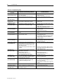


![取扱説明書[SR-PB4/PBE2] (4.17 MB/PDF)](http://vs1.manualzilla.com/store/data/006638833_3-2a716753bfba788481430d553dfac937-150x150.png)