1
BATTERY STATUS PROCESSOR
Battery Status Processor
Model No.
BSP - 500
BSP - 1200
User Manual
Please read this manual before operating your BSP
BSP: User Manual
V1.0.0
Copyright © 2011 Samlex
About the software
This document applies to the version of software V1.4.0 or higher of the BSP. It is possible to check the software with the menu "Information on the
system" or update it with the latest version available on "www.studer-innotec.com/support".
Legal Notice
The use of Samlex devices is the responsibility of the customer in all cases. Samlex reserves the right to make any modification to the product without
prior notice.
Product recycling
The BSP conforms to the European directive 2002/95/EC on hazardous substances and does not contain the following elements: lead, cadmium,
mercury, hexavalent chrome, PBB or PBDE.
To dispose of this product, please use the service for the collection of electrical waste and observe all applicable obligations according to the place
of purchase.
Samlex
BSP
Table of Contents
1. Introduction ............................................................................................................................................... 7
1.1. General ideas over batteries ......................................................................................................... 7
1.1.1. Defining the capacity .......................................................................................................... 7
1.1.2. Capacity and temperature .................................................................................................. 7
1.1.3. Capacity and cells imbalance ............................................................................................ 7
1.1.4. Capacity and discharge current ......................................................................................... 7
1.1.5. Capacity over the battery lifetime ....................................................................................... 8
2. Conventions ............................................................................................................................................. 9
2.1. Symboles ....................................................................................................................................... 9
2.2. Regarding the parameters ............................................................................................................ 9
3. Warranty and liability ............................................................................................................................. 10
3.1. Warranty and liability ................................................................................................................... 10
3.2. Exclusion of warranty .................................................................................................................. 10
3.3. Exclusion of liability ..................................................................................................................... 10
4. Safety precautions ................................................................................................................................. 11
4.1. Generalities ................................................................................................................................. 11
4.2. Warnings ..................................................................................................................................... 11
4.3. Precautions after the use of batteries ......................................................................................... 11
5. Declaration of CE conformity ................................................................................................................. 13
6. Dimensions ............................................................................................................................................. 14
6.1. Views of different sides with dimensions .................................................................................... 14
6.2. Exploded view ............................................................................................................................. 15
7. Installation .............................................................................................................................................. 16
7.1. Mounting ...................................................................................................................................... 16
7.2. Shunt mounting ........................................................................................................................... 16
7.3. Cabling ........................................................................................................................................ 17
7.4. Connecting the communication bus ............................................................................................ 17
8. Quick Start guide ................................................................................................................................... 18
8.1. Choosing the battery capacity .................................................................................................... 18
8.2. Choosing the shunt ..................................................................................................................... 19
8.3. Reset the battery history to zero ................................................................................................ 19
9. Display of the state of the battery ......................................................................................................... 20
9.1. Graph of the state of charge history ........................................................................................... 20
9.2. Values to display ......................................................................................................................... 20
10. Setting of the parameters .................................................................................................................... 22
10.1. Generalities ............................................................................................................................... 22
10.2. Levels of use and of accessibility ............................................................................................. 22
10.1. General menu {6000} ................................................................................................................ 22
10.1.1. Nominal capacity {6001} ................................................................................................. 22
10.1.2. Nominal discharge time (C-rating) {6002} ...................................................................... 22
10.1.3. Nominal current of the shunt {6017} .............................................................................. 22
10.1.4. Nominal voltage of the shunt {6018} .............................................................................. 22
10.1.5. Reset to zero of the battery history {6003} .................................................................... 22
10.1.6. Restore the default settings {6004} ................................................................................ 22
10.1.7. Restore the factory settings {6005} ................................................................................ 23
10.2. Advanced menu {6016} ............................................................................................................. 23
10.2.1. Self discharge coefficient {6019} .................................................................................... 23
10.2.2. Nominal temperature {6020} .......................................................................................... 23
10.2.3. Temperature coefficient {6021} ...................................................................................... 23
User Manual
V1.0.0
Samlex
BSP
10.2.4. Factor of charge efficiency {6022} .................................................................................
10.2.5. Peukert exponent {6023} ................................................................................................
10.2.6. End of charge voltage threshold {6024} .........................................................................
10.2.7. End of charge current threshold {6025} .........................................................................
10.2.8. Minimum time before end of charge {6026} ...................................................................
10.2.9. Force the state of charge at 0 % {6029} ........................................................................
10.2.10. Force the state of charge at 100 % {6030} ..................................................................
10.2.11. Reset to zero the counters on user side {6031} ...........................................................
11. Factory setting values ..........................................................................................................................
Index ...........................................................................................................................................................
V1.0.0
23
23
23
23
23
23
24
24
25
26
User Manual
Samlex
BSP
1. Introduction
The BSP (Battery Status Processor) is designed to monitor lead-acid batteries used with inverter-chargers of
the Xtender range. An advanced algorithm provides the battery state of charge in real time in order to best
optimize its use.
The BSP offers voltage measurement for 12, 24 and 48 V nominal batteries as well as current measurement
with a resistive shunt. Thanks to the Xtender communication bus, the BSP is able to communicate with the
other devices of the system. The remote control RCC-02/-03 makes it possible to configure the BSP and
to display the values that it measures. The remote control enables also the use of the datalogger and the
communication through RS-232. More than this, the Xtender inverters can react to various data in the BSP.
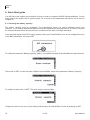
1.1. General ideas over batteries
The lead-acid batteries are energy storage with a complex behaviour. They consist of 2 Volt (V) nominal cells
in series to reach the required voltage. Due to different physical phenomenons they can show, depending
on the conditions, a behaviour quite far from the reservoir that simply fills up and empties out. This is the
reason why the battery state of charge is complex to determine and why a lead-acid battery monitor is not
as precise as, say, a petrol gauge.
The different phenomenons that affect a battery are described here below.
1.1.1. Defining the capacity
The battery capacity is defined as the quantity of electrical charge that a full battery can supply at given current
before reaching a certain voltage. The unit generally used is the Ampere-hour (Ah). An ideal battery of 100 Ah
will for instance supply 10 Amperes (A) in 10 hours or 1 A in 100 hours.
The capacity is usually given for a new battery, at 20 °C, with a discharge down to 1.8 V per cell (10.8 V for
12 V nominal, 21.6 for 24 V and 42.3 V for 48 V). The time of discharge is given by the letter C followed by
the duration in hours, like C10 for 10 hours.
To make them reach the given capacity, the manufacturers charge their batteries according to standard
procedures (for instance as per the norm IEC-60896-11). This kind of charge can last up to many tens of
hours at very high voltages, which is rather far from normal conditions of use. This is why the real available
capacity is lower than what is given by the manufacturer.
1.1.2. Capacity and temperature
The capacity varies according to the temperature of the active substance of the battery. A decrease of the
temperature will lead to a decrease of the capacity.
1.1.3. Capacity and cells imbalance
Despite the fact that always the same current goes through the 2 V cells of a battery, factory differences, even
small, might make their state of charge uneven. In case of imbalance, the most discharged cell determines
the end of discharge.
Therefore the cells in series must always be of the same model and have the same history of use. One of the
objectives of the absorption and equalization steps is to even out the charge of the cells in series.
1.1.4. Capacity and discharge current
The capacity goes down when it comes to big discharge currents. The active substance in the battery needs
time to spread into the cells and a quick discharge will lead to a capacity decrease.
User Manual
V1.0.0
7
Samlex
BSP
To convert the capacity from a discharge duration to another, one can use Peukert formula.
The coefficient n peukert varies from a battery to another and is around 1.25. C
capacity at a known current.
Discharge speed
Capacity at C10
C20
1.19
C3
C50
C100
ref
and I
ref
corresponds to a
0.74
1.50
1.78
Table 1.1. Capacity report with a Peukert coefficient of 1.25
1.1.5. Capacity over the battery lifetime
The capacity decreases along the charge-discharge cycles. The deep discharges have a particularly negative
impact. High ambient temperatures lower also the lifetime.
8
V1.0.0
User Manual
Samlex
BSP
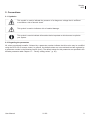
2. Conventions
2.1. Symboles
This symbol is used to indicate the presence of a dangerous voltage that is sufficient
to constitute a risk of electric shock.
This symbol is used to indicate a risk of material damage.
This symbol is used to indicate information that is important or which serves to optimize
your system.
2.2. Regarding the parameters
All values mentioned hereafter, followed by a parameter number indicate that this value may be modified
using the RCC-02/-03 remote control. In general, the default values are not mentioned and are replaced by
a parameter number in the following format: {xxxx}. The default values for this parameter are specified in the
defaults parameter table Chapter 11: “ Factory setting values ” (p. 25) .
User Manual
V1.0.0
9
Samlex
BSP
3. Warranty and liability
3.1. Warranty and liability
During production and assembling, each BSP gets several controls and tests. They are carried out in full
respect of fixed procedures. Each BSP is given a serial number allowing a perfect follow-up of the controls,
in conformity with the specific data of every device. For this reason, it is very important to never remove the
descriptive sticker bearing the serial number. The production, the assembling and the tests of each BSP are
entirely carried out in our factory in Sion (CH). The warranty of this product depends on strictly following the
instructions in this manual. The warranty period for the BSP is 2 years.
3.2. Exclusion of warranty
No warranty will be applied for damages caused by handling, operation or actions that are not described in
this manual. Damages arisen from the following events are not covered by the warranty:
• Overvoltage on the device (Applying a voltage higher than ? Vdc).
• Reverse polarity while connecting the battery.
• Liquid in the device or oxidation due to condensation.
• Failures due to a fall or to a mechanical shock.
• Modifications made without the explicit authorization of Samlex .
• Nuts or screws partially or insufficiently tight during installation or maintenance.
• Damages due to atmospheric overvoltage (lightning).
• Damages due to transport or improper packaging.
• Disappearing of original marking items.
3.3. Exclusion of liability
Installation, commissionning, use and maintenance of this device can not be supervised by the company
Samlex. For this reason, we do not accept any liability for the damages, the costs or the losses generated
either by an installation that is not conforming to the prescriptions, by a defectuous operation or by a poor
maintenance. The use of this device is under the responsibility of the end-user. This device is neither designed
nor guaranteed for the supply of life support applications or any other critical application with potential risks
for human beings of for the environment. We shall assume no liability for patent infringement or other third
party rights involved in the use of this device.
10
V1.0.0
User Manual
Samlex
BSP
4. Safety precautions
4.1. Generalities
Do read carefully all safety instructions before proceeding to the installation and commissionning of the
device. Not respecting these instructions might constitute a lethal physical danger but can also damage the
functionnalities of the device. Therefore do keep this manual close to the device.
Do, for any installation, follow strictly the local and national norms and regulations in
force.
4.2. Warnings
Danger of electrical shock!
• This device is used together with a permanent energy source (battery bank) and can also receive an
alternative source at its input. Before any handling it is then necessary to disconnect all energy sources
from the device.
• Even when the device has been disconnected from its supply source, there might remain a dangerous
voltage at the outputs. To avoid any accident, it is necessary, after disconnection, to wait at least 30 seconds
before operating on the device.
• Never use this device in a place where explosions might occur. Do refer to the indications of the battery
manufacturer to ensure of the compatibility of the battery with the device. The safety instructions of the
battery manufacturer have to be followed striclty too!
• Wherever the installation, the person in charge of installation and commissionning must know perfectly the
safety measures and the prescriptions in force in the country. Therefore, the whole maintenance must be
carried out by a qualified staff.
• All components connected to this device must be conform to the laws and regulations in force. The
persons without a written authorization from Samlex are forbidden to do any change, modification or repair
whatsoever. Regarding authorized modifications and replacements, only genuine components shall be
used.
• This device is meant for a use only indoor and must under no circumstances stand in the rain, the snow
or any other humid or dusty environment.
• In case of use in motor vehicles this device must also be protected against vibrations by absorbing
components.
4.3. Precautions after the use of batteries
Lead acid batteries with liquid electrolyte produce a highly explosive gas during normal operation. No source
of spark or of fire should be present in the closeness of the batteries. The batteries must be installed in a wellventilated space and mounted so as to avoid accidental short circuits while connecting them.
Never charge frozen batteries!
During any work on batteries, a second person must be present in case a problem occurs that requires
assistance. There should be within reach enough fresh water and soap for an immediate washing of the
User Manual
V1.0.0
11
Samlex
BSP
skin or the eyes in case of accidental contact with acid. Should it happen, they must be washed carefully
during at least 15 minutes with cold water. It is then necessary to immediately consult a doctor. The acid of
a battery can be neutralized with baking powder. A fair quantity of baking powder must be kept available on
that purpose. During work with metallic tools close to the batteries, a particuliar attention is required. Tool like
screwdrivers, spanners open-end etc... can generate short circuits. The sparks arisen from short circuits can
lead to the explosion of a battery. During work on the batteries, all personal metallic items like rings, watches
with metallic strap, earrings must be removed. The current supplied by the batteries in short circuit is strong
enough to melt the metal and to cause serious burns.
12
V1.0.0
User Manual
Samlex
BSP
DECLARATION OF CONFORMITY
IMPORTER :
Samlex Europe B.V.
ADDRESS
ARIS VAN BROEKWEG 15
1507 BA ZAANDAM
The Netherlands
:
Declares that the following products:
PRODUCT TYPE
:
Battery Status Processor
BRAND
:
Samlex
BSP 500, BSP 1200
Standards to which conformity is declared:
- EN61000-6-1
- EN61000-6-3
- EN61000-3-2
- EN55022
- EN55014
Signed
: Marcel van Veen
Authority
: Managing Director
User Manual
Date: 21 February 2011
V1.0.0
13
Samlex
BSP
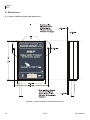
6. Dimensions
6.1. Views of different sides with dimensions
Figure 6.1. Views of different sides with dimensions
14
V1.0.0
User Manual
Samlex
BSP
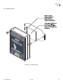
6.2. Exploded view
Figure 6.2. Exploded view
User Manual
V1.0.0
15
Samlex
BSP
7. Installation
The BSP must be mounted as close as possible to the battery. In this way, the measurement perturbations
are minimized and the temperature sensor integrated in the box gives a more accurate measure of the battery
temperature.
Figure 7.1. Connecting schematic of the BSP
7.1. Mounting
Ideally the BSP is stuck directly to the battery. It can also be mounted close to the battery by means of the
fixing plate supplied with (see Figure 6.2 (p. 15)).
The direct mounting on the battery offers a more precise measurement of the battery temperature. While
changing the battery bank, the BSP will have to be stuck again with a new double-side adhesive.
The BSP must be mounted so as to avoid any contact with acid from the battery. It should
be taken care of fixing it vertically with the communication bus connectors downwards.
7.2. Shunt mounting
The shunt supplied with the device allows the measurement of the battery current. It must imperatively be
installed in series with the negative terminal of the battery. The connection (a) of the Figure 7.1 must be as
short as possible. For a good operating of the charge estimating algorithm, all the current must go through
the shunt. No other conductive component shall be connected to the negative terminal of the battery.
16
V1.0.0
User Manual
Samlex
BSP
The shunt must be exclusively mounted on the negative terminal of the battery.
7.3. Cabling
The cabling schematic is available on Figure 7.1. The cabling procedure is as follows:
1. Connect the shunt to the negative terminal of the battery (a).
2. Connect the crimped terminal on the white and yellow wires of the BSP cable to the measuring screw on
the negative terminal of the battery (b).
3. Connect the terminal of the green wire of the BSP cable to the measuring screw of the shunt, inverter
and charge side (c).
4. Connect the red wire with a fuse to the positive terminal of the battery (d).
It might happen while connecting the red wire to the battery that a spark is
generated by the surge current of the device's internal power supply. No damage
is likely to happen.
5. Connect the inverter(s), the solar regulators and any other DC charge to the second bolt of the shunt, for
the negative and the positive terminal of the battery (e).
6. Connect the communication cable in the devices chain and activate the linkend, if necessary (f). For more
information see the Section 7.4.
7.4. Connecting the communication bus
The devices of the Xtender range are equipped with a owned communication bus for data exchange,
configuration and updating of the system. Connection is being made by linking the devices with the
communication cables. One gets then a bus online where a linkend must be activated on the devices on each
end, to obtain the configuration of the Figure 7.2 .
Each device is equipped with a switch offering to choose between open "O" or terminated "T". The devices
at the end of the line must be set on "T" and all the others on "O".
A wrong setting of the linkends can lead to an erratic running of the installation or impede
its updating.
Figure 7.2. The communication bus online of the system Xtender
User Manual
V1.0.0
17
Samlex
BSP
8. Quick Start guide
You will find in this chapter the procedure to follow in order to configure the BSP during installation. For the
major part of the systems this is good enough. For a full list of the parameters that can be set do refer to
Chapter 10.
8.1. Choosing the battery capacity
The battery capacity must be configured. The manufacturer gives it at various discharge times (see
Section 1.1.1). If several capacities at different times are supplied, the discharge time in 10 hours (C10) must
be choosen because these are the reference conditions for the state of charge calculation.
From the initial display of the RCC and by means of the keys UP and DOWN, move to the configuration menu
of the BSP parameters, then push SET.
To modify the parameter "Battery Capacity" {6001}, move with the arrows UP and DOWN to the general menu.
Then push on SET to enter the menu. With the arrow DOWN, move to the parameter "Battery Capacity".
To modify its value push on SET. The value turns in reverse vidéo.
Change the value for the one of your battery with the keys UP and DOWN. Confirm by pushing on SET.
18
V1.0.0
User Manual
Samlex
BSP
Then, configure the parameter "Nominal Discharge Time(C-rating)" {6002} the same way as for the battery
capacity.
8.2. Choosing the shunt
If your are using a shunt supplied with the BSP-500, the BSP is configured for it and you can go directly to
the next section.
Otherwise, the measuring shunt must be configured. The shunts are meant to supply a measuring nominal
voltage at a nominal current. If you use the shunt supplied with the BSP-1200, the nominal current is 1200
A at 50 mV. If you use your own shunt, the current and the nominal voltage are given by the manufacturer
and are often printed on the shunt.
The parameters "Nominal Current of the shunt" {6017} and "Nominal Voltage of the shunt" {6018} of the
advanced menu enable to configure the BSP for a given shunt.
8.3. Reset the battery history to zero
If you install the BSP for the fisrt time or if the battery has been changed, you must reset the battery history
to zero, by means of the parameter {6003}.
User Manual
V1.0.0
19
Samlex
BSP
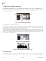
9. Display of the state of the battery
On installations with a BSP, the view over information on the battery of the Figure 9.1 is added to the RCC.
In area (A), four values of the BSP are displayed. The symbol of the battery in (B) gives an quick overview of
the state of charge (SoC). The direction of the current is given in (C). An arrow upwards means the charge,
downwards, the discharge.
Figure 9.1. View of the state of the battery
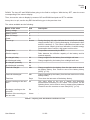
9.1. Graph of the state of charge history
It is possible to see the battery state of charge of the last 5 days on the RCC. On that purpose, from the view
over the battery information, you enter in selection mode with the key SET. The battery is then selected as
on the Figure 9.2. The key SET allows then to display the graph.
The graph of the state of charge of the Figure 9.3 is then displayed. On the horizontal scale are today and
the last 4 days. The graduations indicate every hour from midnight to midnight. Each horizontal pixel means
one hour. The vertical axis gives the state of charge of the battery. The graduations mean 20, 40, 60, 80 and
100 % and one pixel means 2 %.
Figure 9.2. View with selected battery
Figure 9.3. View of the state of charge history graph
9.2. Values to display
It is possible to modify the values to display on the battery view. For that, from the basic view of the Figure 9.1
push on SET. The battery is then selected as on the Figure 9.2. Go to the first value displayed with the key
20
V1.0.0
User Manual
Samlex
BSP
DOWN. The keys UP and DOWN allow going to the field to configure. With the key SET, enter the menu
corresponding to the value to display.
Then, choose the value to display by means of UP and DOWN and push on SET to validate.
At any time, to quit, use the key ESC that will bring you to the previous view.
The values available are the following:
Name of the value
Unit
Description
Battery current
A
-
Battery voltage
V
State of Charge
%
Power
W
Time to go
hh:mm
Temperature
°C
Ah charged today
Ah
Ah charged yesterday
Ah
Relative capacity
-
Ah discharged today
Ah
Ah discharged yesterday
Ah
Total kAh charged
kAh
Total kAh discharged
kAh
Total time
Days
Discharge counting on the
user side
Ah
Charge counting on the user
side
Duration of the counting on
the user side
Ah
Hours
-
During charging, this value indicates the time before the battery
charge reaches 100 %. During discharging, it indicates the time
before it reaches 0 %. This value is calculated on basis of the
present current. What it gives is an indication. A variable energy
consumption has of course a big impact on this value.
Temperature measured by the BSP.
Ratio between the effective capacity of the battery and its
nominal capacity.
Charge supplied to the battery from midnight until now.
Charge supplied by the battery from midnight until now.
-
Charge supplied to the battery from the last reset to zero of
the battery history. See “Reset to zero of the battery history
{6003}” (p. 22) .
Charge supplied by the battery from the last reset to zero of the
battery history.
Time since the last reset of the battery history.
This value offers to the user a charge and discharge
measurement according to his needs. This counter, as the
following three, can be reset to zero by means of the parameter
“Reset to zero the counters on user side {6031}” (p. 24).
-
Table 9.1. Capacity ratio with Peukert coefficient of 1.25
User Manual
V1.0.0
21
Samlex
BSP
10. Setting of the parameters
A full list of accessible parameters can be found in Chapter 11 (p. 25).
10.1. Generalities
The configuration is carried out on the RCC by means of the BSP parameters menu. Generally the settings
described in Chapter 8: “Quick Start guide” (p. 18) are enough for a good operation of the BSP. It is however
possible to modify many other parameters described in this chapter.
10.2. Levels of use and of accessibility
The functions described below correspond to the level EXPERT. As per the user level selected, the access
to all these functions might not be possible. Do refer to the chapter user level setting in the remote control
manual for more information about this matter.
10.1. General menu {6000}
The parameters for a basic configuration of the BSP are in this menu.
10.1.1. Nominal capacity {6001}
Battery nominal capacity. It is given for the nominal discharge time defined by the parameter {6002}.
10.1.2. Nominal discharge time (C-rating) {6002}
Discharge time used to give the battery nominal capacity of the parameter {6001}.
10.1.3. Nominal current of the shunt {6017}
This parameter enables to adjust the BSP measurement to the shunt. It must be set according to the nominal
voltage of the shunt (parameter {6018}). For instance for the shunt 1200 A supplied with the BSP-1200, the
setting will be 1200 A and 50 mV.
10.1.4. Nominal voltage of the shunt {6018}
See parameter {6017}.
10.1.5. Reset to zero of the battery history {6003}
This parameter enables to reset to zero all counters of the Section 9.2 and the algorithm during installation
on a new battery.
This parameter should normally not be used if the battery has not been changed,
because then the history (total current, estimated capacity) is lost.
10.1.6. Restore the default settings {6004}
Use this parameter to restore the initial settings of the BSP.
If your installer has made some settings while commissioning your installation, this
function restores his settings and not the factory ones.
22
V1.0.0
User Manual
Samlex
BSP
10.1.7. Restore the factory settings {6005}
With this function you can find the factory settings. For each parameter, not only the factory value is restored
but also the limits and the user level. This function is only accessible with the level installer.
10.2. Advanced menu {6016}
The advanced parameters for a BSP configuration.
10.2.1. Self discharge coefficient {6019}
A battery gets discharged over time even when no current is consumed. This parameter allows to take this
phenomenon into account.
10.2.2. Nominal temperature {6020}
The battery parameters are specified for a given temperature, which can be set by means of this parameter.
10.2.3. Temperature coefficient {6021}
The available capacity diminishes with the decrease of the temperature. This coefficient enables to take this
factor into account.
10.2.4. Factor of charge efficiency {6022}
During charging, less Ah are stored into the battery than during discharging. The ratio discharge/charge can
be set with this parameter.
10.2.5. Peukert exponent {6023}
The capacity varies according to the discharge current (see Section 1.1.4). With this parameter one can set
the Peukert exponent that goes along with the nominal capacity {6001} and nominal discharge time .
10.2.6. End of charge voltage threshold {6024}
See explanation at parameter {6026}.
10.2.7. End of charge current threshold {6025}
See explanation at parameter {6026}.
10.2.8. Minimum time before end of charge {6026}
This parameter with the parameters {6024} and {6025} controls the synchronization of the state of charge
at 100 % end of charge.
To make it happens:
• the voltage has to be above the parameter {6024}
• the current has to be below the parameter {6025}
• and this during the period defined by the parameter {6026}
10.2.9. Force the state of charge at 0 % {6029}
This parameter enables to force the state of charge at 0 %.
User Manual
V1.0.0
23
Samlex
BSP
10.2.10. Force the state of charge at 100 % {6030}
This parameter enables to force the state of charge at 100 %.
10.2.11. Reset to zero the counters on user side {6031}
This parameter allows to reset to zero the counters of charge, discharge and time on user side of Section 9.2.
24
V1.0.0
User Manual
User Manual
Reset of battery history
6005
V1.0.0
Expert 6026
Expert 6025
Expert 6024
Expert 6042
Expert 6023
13.2
No
1.25
80
5
0
7.98
No
1
50
0
0
0
S
S
S
S
10
10
1
20
300
20
240
2
No
1.25
80
.5
20
3
S
S
S
S
50
17.52 26.4
Yes
1.5
100
3
40
25
S
S
S
S
200
20
10000 500
100
5
0
300
20
Yes
1.5
100
3
40
25
S
S
S
S
200
240
2
No
1.25
80
.5
20
3
S
S
S
S
50
20
10000 500
100
5
0
300
20
Yes
1.5
100
3
40
25
S
S
S
S
200
10000
100
20000
Max
48 V
31.92 70.08
No
1
50
0
0
0
S
S
S
S
10
10
1
20
FactoryMin
20000 110
Max
15.96 35.04 52.8
No
1
50
0
0
0
S
S
S
S
10
10
1
20
24 V
FactoryMin
20000 110
Max
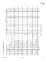
Table 11.1. Factory setting values
240
%cap 2
Minimum duration before end of s
charge
End of charge current level
End of charge voltage level
V
%
%cap/ .5
°C
20
S
S
S
S
50
500
20
110
12 V
FactoryMin
%/
3
month
°C
mV
Activate the end of charge No/
synchronization
Yes
Peukert's exponent
Charge efficiency factor
Temperature coefficient
Expert 6022
Expert 6021
Nominal temperature
Self-discharge rate
Reset of user counters
Advanced settings
Restore factory settings
Restore default settings
Expert 6020
Expert 6019
Expert 6031
Expert 6016
Inst.
Basic 6004
Nominal shunt voltage
Expert 6003
Basic 6018
Nominal shunt current
Basic 6017
A
Nominal discharge duration (C- h
rating)
Ah
Basic 6002
Basic 6001
Nominal capacity
Unit
Basic settings
Parameter
Basic 6000
Level User
ref.
11. Factory setting values
Samlex
BSP
25
Samlex
BSP
Index
Symbols
{6000} General menu, 22
{6001} Nominal capacity, 22
{6002} Nominal discharge time (C-rating), 22
{6003} Reset to zero of the battery history, 22
{6004} Restore the default settings, 22
{6005} Restore the factory settings, 23
{6016} Advanced menu, 23
{6017} Nominal current of the shunt, 22
{6018} Nominal voltage of the shunt, 22
{6019} Self discharge coefficient, 23
{6020} Nominal temperature, 23
{6021} Temperature coefficient, 23
{6022} Factor of charge efficiency, 23
{6023} Peukert exponent, 23
{6024} End of charge voltage threshold, 23
{6025} End of charge current threshold, 23
{6026} Minimum time before end of charge, 23
{6029} Force the state of charge at 0 %, 23
{6030} Force the state of charge at 100 %, 24
{6031} Reset to zero the counters on user side, 24
26
V1.0.0
User Manual
www.samlex.com
www.samlex-solar.com