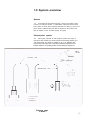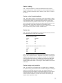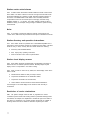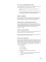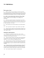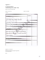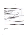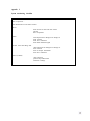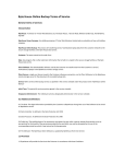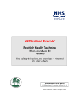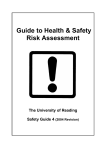
1
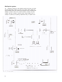
HEALTH TECHNICAL MEMORANDUM 2009
Pneumatic air tube transport systems
Design considerations and good practice
guide
1995
STATUS IN WALES
APPLIES
For queries on the status of this document contact
[email protected] or telephone 029 2031 5512
Status Note amended March 2013
Health Technical
Memorandum 2009
Design considerations and
Good practice guide
Pneumatic air tube
transport systems
London : HMSO
© Crown copyright 1995
Applications for reproduction should be made to HMSO Copyright Unit
First published 1995
ISBN 0 11 322193 2
HMSO
Standing order service
Placing a standing order with HMSO BOOKS enables a
customer to receive future titles in this series automatically
as published. This saves the time, trouble and expense of
placing individual orders and avoids the problem of
knowing when to do so. For details please write to HMSO
BOOKS (PC 13A/1), Publications Centre, PO Box 276,
London SW8 5DT quoting reference 14.02.017.
The standing order service also enables customers to
receive automatically as published all material of their
choice which additionally saves extensive catalogue
research. The scope and selectivity of the service has been
extended by new techniques, and there are more than
3,500 classifications to choose from. A special leaflet
describing the service in detail may be obtained on
request.
About this publication
Health Technical Memorandum (HTM)
e.
commissioning;
2009 gives comprehensive advice and
guidance on the design, installation and
f . operation; and
operation of pneumatic air tube
transport systems in healthcare
premises.
g.
management
of pneumatic air tube transport
It is applicable to new and existing sites,
systems.
and is for use at various stages during
the inception, design, upgrading,
It is published as two separate volumes,
refurbishment and extension of a
each addressing a specialist discipline:
pneumatic air tube transport system.
This HTM covers pneumatic air tube
•
Management policy - outlines
transport systems utilising tubes of up
the overall responsibility of
to 160 mm diameter. Further
managers of healthcare
information on large bore air tube
premises and outlines their legal
vacuum systems for use in hospitals for
obligations in setting up and
the handling of waste and laundry
operating a pneumatic air tube
items is subject to further review. HTM
transport system. It also
2009 focuses on the:
summarises the technical
aspects involved;
a. legal and mandatory
requirements;
•
this volume - Design
considerations and Good
b. design considerations;
practice guide - does not set
out to give instruction in design
c. installation;
work but highlights the overall
requirements and considerations
d. maintenance;
that should be applied to the
design of pneumatic air tube
transport systems. The chapter
on validation and verification
b. the Health and Personal Social
details the requirements for
Services Management Executive
ensuring that the pneumatic air
in Northern Ireland;
tube transport system is formally
tested and certified as to
c. the National Health Service in
Scotland Management Executive;
contract and manufactured to
the highest level of quality
assurance. The importance of
and set standards consistent with
commissioning is emphasised
Departmental Cost Allowance Guides.
and tests that may be carried out
on site are provided in the
This HTM was written with the advice
appendices. The operational
and assistance of experts in the NHS
management chapter provides
and industry.
information for those responsible
for managing the day-to-day
References to legislation appearing in
operation and maintenance of
the main text of this guidance apply in
the system. Safe systems of
England and Wales. Where references
work, record keeping and legal
differ for Scotland and/or Northern
obligations are included.
Ireland these are given in marginal
notes.
Guidance in this HTM is complemented
by the library of National Health Service
Where appropriate, marginal notes are
Model Engineering Specifications.
also used to amplify the text.
Users of the guidance are advised to
refer to the relevant specifications.
The contents of this HTM in terms of
management policy, operational policy
and technical guidance are endorsed
by:
a. the Welsh Office for the NHS in
Wales;
Contents
About this publication
1
System overview page 3
2
Assessment of requirements page 6
3
Performance requirements page 8
4
Validation and verification page 14
5
Operational management page 18
6
Routine maintenance page 22
7
Definitions page 24
Appendices page 26
References and bibliography page 31
Other publications in this series page 34
About NHS Estates page 35
1.0 System overview
General
1.1
A pneumatic air tube transport system - which may be either a pointto-point or a multi-point system - is a distribution network of tubes through
which carriers of various sizes containing small items are driven by air flow. The
prime mover is a blower which can alter the direction of the air flow in the
tube as required to move the carrier through the system
Point-to-point system
1.2
Point-to-point pneumatic air tube transport systems (see Figure 1)
provide two-way transfer via a single continuous tube linking stations up to
1000 metres apart. This system is suitable for use in an application that
requires simple operation and a dedicated link between departments, for
example between an operating theatre and the pathology department.
Previous page
is blank
Multi-point system
Multi-point pneumatic air tube transport systems (see Figure 2) provide
1.3
full intercommunication between all points in the system. Where systems are
large and traffic is heavy, the network may be split into zones. This allows local
transport of carriers in each zone, as well as transfer to another zone when
required. This type of system is commonly used in large hospitals, with, for
example, the pharmacy and pathology departments being in separate zones.
Diverters
Diverters are used to route carriers through the network and sometimes
1.4
across zones. The number and location of diverters should be agreed at local
level between the designer and hospital staff, but generally they should be
used economically and be positioned to minimise the system tube length.
System control
Multi point systems are controlled centrally by a dedicated micro1.5
processor or computer. The controller receives transfer instructions, carries out
continuous monitoring of the system and provides system status information. If
required, cleaning cycles may be carried out at pre-determined intervals to
keep the pipework free of dust. The control system should allow
reconfiguration of the network as required. Stations can be operational on a
9am to 5pm basis, with override facilities as required, or 24 hours a day,
according to the requirements of a particular department.
Stations
A station may be an end unit (one at the end of a branch), for example
1.6
station A in Figure 2, or a through station (carriers may pass straight through
it), for example station B in Figure 2. Although the stations operate in slightly
different ways, send and receive operations may be carried out at each one.
Each station should include a user interface, which is normally in the form of a
keypad and display unit.
1.7
Features of a typical hospital pneumatic air tube transport system will
include:
Network tubing: 110 mm diameter and normally uPVC but, if required
for protection, steel tube may be used for some sections
Automatic send and receive stations
Full intercommunication between all stations
Prioritisation of carrier delivery
Multi zone with communication between zones
Security measures for the transfer of certain products, such as drugs
Leak proof carriers and sealed insert bags for samples (spillage may
then be contained within carrier)
2.0 Assessment of requirements
2.1
The cost of installing and maintaining a pneumatic air tube transport
system should be offset by the savings made in the time staff, and in
particuliar portering staff, spend in the manual transfer of samples between
departments. The decision to install a system should be made following an
analysis of traffic in small items, including drugs and pathological samples,
carried between departments by staff. The main users of the system in an
acute hospital will normally be the pathology and pharmacy departments.
Security measures will need to be incorporated into general operational
procedures and consideration should be given to the location of stations in
controlled access areas.
The results of the traffic survey will help to identify where stations
2.2
should be allocated. Stations may be shared between departments to reduce
the overall cost of the installation, for example one station for adjacent wards
which are possibly already sharing facilities.
The system should be capable of transferring packages safely and
2.3
securely between all or only selected stations within the network which may
cover a single hospital or a number of adjacent hospital sites.
2.4
A central controller should continuously poll all stations in sequence to
initiate the required send/receive sequence for carriers loaded into stations. A
system of send/receive priorities for each station ensures that urgent items are
handled with minimum delay. A maximum time should be set to ensure carriers
are not indefinitely parked in the system.
It should be possible to take manual control of the system to override
2.5
the central control (with a sub set of operations available at all stations) to
allow for example manual purging of the system in the event of a carrier
becoming blocked.
Two separate purging procedures should be provided: system wide; and
2.6
specific to a station to assist in recovering carriers lost in the system, by setting
the system to pull/push carriers to the specified station.
Printed reports of status/alarms/traffic should be provided by the central
2.7
controller as required.
For large systems, the network will be faster and more efficient if it is
2.8
split into zones. This will allow the majority of traffic to be contained within a
local zone and will reduce the number of inter zone transfers. Each zone will
have a dedicated, suitably sized blower (see paragraph 3.2).
2.9
Carriers can be colour coded for each department. Identification of
specific users may be required by the infection control officer. Empty colour
coded carriers can be returned automatically to the relevant station.
Location of major system components
2.10 The blower should be housed in a clean, dust-free environment isolated
from areas in which patients may be sleeping.
2.11 A filter may be required in the air intake to the system to protect
samples or aseptic areas. Planning teams should seek the advice of the
infection control officer.
2.12 The station should be located in a secure area preferably only accessible
to staff and which can be locked-if the area is vacated. If a station is to be
shared, access arrangements should be agreed and the security of the station
assigned to one department.
2.13
Diverters should be located in service areas with good access for
maintenance.
2.14 Tubing should be routed in ducts and ceiling voids if space is available.
The tubing will require large bend radii to avoid blockages. If the tube has to
be routed externally or in hostile environments, it should be protected and
insulated to reduce the risk of damage or condensation occurring within the
pipework.
Safety
2.15 Access to areas that contain send/receive stations should be secured to
prevent unauthorised entry, or provided with a lockable basket/cabinet.
2.16 Plantrooms containing pneumatic air tube transport systems should be
well-illuminated and should permit safe access to all parts of the plant
requiring inspection, service and maintenance.
Security for drug transfer
2.17
The security system should be controlled from the pharmacy station.
2.18 Under normal operation, an arriving carrier is automatically released
and deposited into the basket. Under the pharmacy security system this may
be modified according to level of security selected by the despatcher in the
pharmacy.
2.19 Each station in the system may have an unique code for receiving
secure drug carriers. The entry of the code will signal to the central controller
that the transaction must be secure. The carrier should not be discharged until
the correct code has been entered at the receiving station. The code should be
set by the system manager. A station may require a number of security codes
to enable individual control by departments sharing a station.
3.0 Performance requirements
General
Equipment that requires regular inspection should not need to have its
3.1
covers removed but rather should be arranged so that visual inspection can be
carried out easily. The provision of viewing ports and illumination within the
duct will facilitate this approach.
Blower capacity
3.2
Blower capacity should be established by the system designer and
should be sufficient for transporting the carriers through the local zone at the
agreed velocity and if required across to other zones connected in the network.
Tubing
The installation should normally be carried out using 110 mm diameter
3.3
hard uPVC tubing to DIN8061/62 Group B1 specification with all joints solvent
welded. If certain sections of the system need to be protected, steel tubing
should be used.
3.4
A smooth internal bore must be retained throughout the system.
Where tubing passes through a wall, floor, ceiling or other barrier, the
3.5
contractor should ensure that the fire rating of the barrier is not reduced. This
can be achieved by installing crushing type intumescent fire sleeves or collars.
Reference should be made to Firecode, Firecode in Scotland, or Firecode in
Northern Ireland as appropriate.
3.6
All tubing pipework should be labelled to indicate its purpose
3.7
Tubing may be prone to a build up of dust due to the electrostatic
charge created by the action of transporting the carriers through the tube. This
can be overcome by earthing the tube.
Carrier velocity
The average velocity of full carriers between stations should not exceed
3.8
6 metres per second (m/s). The carrier velocity may sometimes need to be
lower to protect the integrity of samples: a velocity of 5 m/s is used at a
number of hospital sites. System velocity should be agreed with the pathology
and pharmacy department. The system should gradually accelerate and then
slow down the carrier on arrival at the destination station.
Return carrier velocity
Empty carriers can be transported at 10 m/s if required by the system
3.9
manager. However this may cause additional noise and the majority of systems
may operate satisfactorily using a velocity of 5 m/s.
Carrier braking
3.10 Carrier deceleration on arrival at the destination station should be
carried out using the “air column technique” in which an approaching carrier
activates a pressure release device and is braked by a still column of air above
the station.
Carrier arrival baskets/cabinets
3.11 Each station should be provided with a carrier arrival basket or cabinet
of sufficient size and capacity to accommodate the number of carriers allotted
to the appropriate station. The basket should be fixed to the wall or floor
under the station and be positioned to allow carriers of an agreed number to
arrive at the station and be stored within the basket without blocking the exit
tube of the station. If the station is located in an area which may be
unmanned or is accessible to the public, the basket or cabinet should be fitted
with a lock and the key should be under controlled access.
Carrier size
3.12 The carrier sizes available for a 110 mm diameter tube with a minimum
bend radius of 650 mm or 800 mm are as follows:
650 mm tube bend radius
Length
330
230
185
180
Diameter
70
80
80
80
800 mm tube bend radius (in addition to above)
Length
330
220
415
Diameter
76
86
65
3.13 A larger bend radius of up to 800 mm may be adopted to increase the
range in size of carrier that may be transported via the system: however, space
limitations may restrict this use in some sites. A full survey over the proposed
route of the tube will be required to establish the minimum bend radius that
can practicably be used in the system. Pneumatic air tube transport system
suppliers should provide advice on the range of carriers suitable for the chosen
bend radius.
Carrier design and provision
3.14 The carriers may be designed with one openable end or, alternatively,
be capable of being opened at both ends to facilitate loading and unloading of
items such as blood bags which fill the carrier. The carrier lids should be
designed so that the lid is positively secured before loading the carrier into the
system (screwed lids may unscrew from the carrier within the system). The
carriers should be transparent, to enable the contents to be viewed by the
recipient before opening the carrier.
Station carrier arrival alarms
3.15 A station carrier arrival alarm should indicate the arrival of each carrier
at the station. The alarm could be in the form of a light which should remain
lit until acknowledged by a member of staff, therefore accepting delivery of
the carrier. If an audible alarm is also fitted, a time out facility should be
incorporated to time out the sounder (but not the light), the timer being
adjustable between 0 - 15 minutes. The system manager should be able to
disable the facility, for example, during the night or whilst the system is being
commissioned.
Noise
3.16 If a sounder is used at the station to indicate “carrier arrival” and
“carrier send”, staff should be provided with the option to disable the sounder.
Station directory and operation instructions
3.17 Each station should be provided with a laminated/encapsulated list of
instructions, which should be mounted on or adjacent to the station. The label
should be easy to clean, securely fixed and should include the following:
a. a directory of all available stations;
b. clear, step-by-step operating instructions;
c. action to be taken in the event of system failure.
Station visual display screens
3.18 Each station should be equipped with a visual display unit having at
least a two line, 16 character per line minimum. Normally a liquid crystal
display screen is incorporated in the station housing.
3.19 When a carrier is sent from any station, the visual display screen at the
station should:
a. indicate that the station is ready to accept a carrier;
b. request the identification of the destination station;
c. request the confirmation of the instruction;
d. confirm that the carrier has arrived at the selected destination.
Text messages on the visual display screen should be clear and easy to
understand
Restriction of carrier destinations
3.20 The system manager should be able to programme the central
controller to prevent users from sending carriers to particular station(s) within
the network, for example, if a department is vacated at night or if a station is
shut down for maintenance. The system manager should also be capable of
diverting carriers sent to one station to another if required by the users.
Incorrect or unobtainable destination
3.21 The management of carriers directed to a closed/barred or non-existent
station will depend upon the structure of the send station:
a. bottom loaded stations: the carrier will not be accepted into the
system;
b. exposed carrier stations: the carrier should be removed manually; or
c. covered carrier stations: the carrier will be accepted into the system but
will be rejected immediately into the stations arrivals basket.
Station availability
3.22 If a station or the system is non operational for any reason the screen
should display “system out of use” or “station out of use”, as appropriate.
This is in addition to the warning light requirement stated elsewhere.
Station/system availability indication light
3.23 The station display should incorporate a station availability light: a
green light indicating that the station is open and available for use and a red
light indicating the station/system is out of use due to a fault or other failure.
Any fault or other failure should show up as a system alarm on the
main/master controller.
Station mounting heights
3.24 For top side and front entry stations the mounting height to the top of
the cabinet should be 1.6 m above finished floor level.’
3.25 For bottom loading stations the mounting height from the bottom of
the station should be 1.2 m to finished floor level.
Active carrier monitoring
3.26 The carrier’s progress throughout the system should be monitored. This
should be carried out by using beam detectors or micro switches. The beam
detectors should only operate in the non-visible part of the light spectrum. The
detectors should not be sensitive to daylight or any form of artificial lighting as
this will prevent fault detection. It should be possible to request progress
reports in the following areas:
a. at send station:
(i) carrier loaded;
(ii) carrier accepted;
(iii) carrier despatched;
b. at diverter and carrier storage locations (if installed):
(i) arrival;
(ii) location of carrier in storage system/multi send station/remove
storage magazines/zonal interchange unit;
(iii) departure.
3.27 The above should apply to any other system component with moving
parts designed to accommodate/facilitate the transport of carriers
a . at receiving station:
(i) carrier approaching;
(ii) carrier arrived;
(iii) carrier exit tube clear;
System automatic purge
3.28 The system should be capable of carrying out an initial automatic
purge, in an attempt to clear a blockage or sticking carrier, with the sticking
carrier being purged to the source station. If the purging operation fails to
deliver the carrier to the assigned destination, the carriers may be diverted to a
designated station. If the automatic purge is not successful the system will
require to be reset manually. In addition to this a volt free contact may be
provided to allow connectron to the hospital building energy management
system (BEMS) to indicate an alarm condition.
Blocked exit tube at a station
3.29 The system should be capable of attempting to automatically clear and
eject a blocked carrier in the exit tube at any station by agitating the station’s
diverter/carrier transfer mechanism.
Breakage or spillage of samples
3.30 Spillages within the tubing should be a very rare occurrence if the
system is being used in a safe manner. Any high risk samples should be placed
in a leak proof container (see Figure 3), which in turn is placed in a sealed
plastic bag incorporating a request form that Indicates high risk samples. It is
preferable for all known high risk samples to be transported individually in a
carrier, so that if breakages should occur within the carrier, other samples are
not contaminated. The carrier should be transparent to allow operators to
visually inspect carriers received and detect any spillages within the carrier. If
the carrier contains a spillage then it should be dealt with according to
procedures agreed by the infection control officer, or other approved quaIified
person.
3.31 The carriers should incorporate a leak proof seal to prevent fluid
escaping during transportation in the system and whilst being handled by staff.
The carriers should be autoclavable, so that sterilization of the interior and
exterior of the carrier can be achieved.
3.32 If leaking samples are allowed to enter the tube system or a station, the
station should be Isolated and the infection control officer contacted to
establish how much of the system must be Isolated until removal of the carrier
and disinfection/cleaning of the areas affected can be completed. The
disinfection procedure or clearing will depend on the nature and level of risk
Imposed by the contaminant; each incident will need to be assessed separately.
3.33 Disinfection or cleaning procedures should be determined locally in line
with the organisation’s policy.
Transaction records
3.34 The system’s central processor should be equipped with sufficient
memory to hold one week’s transacttons of carrier Journeys, including records
of all diverter positrons, station positrons etc. To provide an audit trail and to
assist with fault findings, this information should be capable of being
downloaded to a printer and, in addition, the records should be stored on a
computer file on hard disk or other magnetic material.
3.35 Faults on the system should also be recorded in print form as they
occur.
4.0 Validation and verification
General commissioning
4.1
The commissioning of pneumatic air tube transport systems helps to
ensure that users develop confidence in operating the system. The majority of
problems reported from existing installations can be traced back to operator
error or software bugs not found during commissioning. All functions of the
system must be thoroughly tested including a full software check for
microprocessors and computer systems to ensure that software bugs are
eliminated.
The test sheet in Appendix 1 is generic and will probably need to be
4.2
modified to meet the requirements of the manufacturer of the actual system.
Additional sheets will be required for other items and these should be created
by the designer with advice from the manufacturer.
The project file (as defined in the Condam regulations) should be
4.3
available before commissioning commences and should contain:
a.
operation and maintenance manuals for system and all Installed
equipment;
b. full set of “as fitted” drawings;
c. full software listing of all programs used by system
Commissioning personnel
4.4
The objective of commissioning is to ensure that the system fully
complies with the specification. It is unlikely that all of the necessary
commissioning skills will be possessed by one individual; a commissioning team
is therefore usually required.
During the commissioning process a great deal of information about
4.5
the plant will be generated which will form an Invaluable source of reference.
It IS essential to ensure that the records are kept in a project file
(commissioning manual) to be handed over to the client on completion of the
contract together with the maintenance data and “as fitted” drawings.
4.6
The commissioning process should be fully documented at the tender
stage. The correct installation of all system parts will need to be witnessed and
any tests required carried out as construction proceeds, in particular on items
which may have to be covered before completion of the installation. Failure to
establish responsibility for commissioning may delay the completion of the
project or lead to unsatisfactory plant performance.
Commissioning brief
4.7
The commissioning team will require a detailed brief from the system
designer. This should include:
a.
a "user" brief comprising a description of the installation and its
intended mode of operation;
b. the precise design requirements of the particular system;
c . equipment manufacturer’s type test data, commissioning, operation and
maintenance recommendations;
d. drawings showing the layout of the system and positions of items of
plant;
e. wiring diagrams for all electrical equipment associated with the
pneumatic air tube transport system including control circuit details and
any interlocking and safety devices such as emergency stop buttons
adjacent to the item of plant.
4.8
On completion, the system should be subject to performance tests
carried out by the contractor and witnessed by the client’s representative in
accordance with the contract requirements to prove operation of all items,
control sequences and alarms.
The commissioning process may be carried out in the order in which it
4.9
appears in this guidance document. The static checks and visual inspections
should be followed by the dynamic tests, performance tests and finally the
handover procedures.
4.10 On completion of the commissioning and when the system is shown to
meet the design intent the handover documentation should be completed. In
the event of performance not being acceptable, the matter should be dealt
with in accordance with the contract arrangements.
Pre-commissioning checks
4.11 The pre-commissioning checks should consist of visual inspection,
manual operation of equipment, static measurements and functional tests of
Individual components. They should be carried out prior to setting the system
to work and undertaking the dynamic commissioning process.
Standard of installation
4.12
During the installation of the system the following should be witnessed:
a. that the plant and installations have been provided and installed in
accordance with the design specification and drawings;
b.
that all components function correctly;
c.
that the interlocks are operative and in accordance with specification;
d. that the electric circuits are completed, tested and energised;
e. that electric motors have been checked for correct direction of rotation;
f . that the plant is physically complete, and if required insulation is
applied and all ducts and pipework are identified as specified;
g. that the area containing the blower is clean and dust free;
h. that access to all parts of the system is safe and satisfactory.
Cleanliness of installation
4.13
The area around the blower air intake must be free of dust, vegetation,
waste, rubbish, builder’s debris or any other possible source of contamination.
Before setting the system into operation, tubing should be purged to an open
end and cleared of any dirt, dust or debris accumulated during constructron.
Commissioning and testing prior to handover
General description
4.14
Immediately prior to handover the employer’s representative will attend
site together with the engineering supervising officer, the engineer’s
representative and the contractor, to witness the final acceptance testing of all
systems. All information gathered from the completion of commissioning
should be presented together with the “as fixed” drawings and manufacturer’s
operation and maintenance manuals.
4.15
Spot checks should be made and compared with information collated
previously. In the event of spot checks being inconsistent with previously
recorded information the element in question should be rechecked in its
entirety. A check will also be made to ensure all items on the defects list have
been attended to in an acceptable manner. The contractor is advised to ensure
that his subcontractors are aware of the implications of the content of work
contained in commissioning and testing and all due allowance has been made
within the contract programme of work. It should be noted that handover
cannot proceed until testing and commissioning has been completed to the
satisfaction of the engineering supervising officer.
4.16
The blower drive, direction of rotation, speed and current drawn should
be set in accordance with their manufacturer’s instructions.
4.17
After the Installation has been checked to ensure that it is in a
satisfactory and safe condition for start up, it should be set to work and
regulated to enable the plant to meet its design specification.
Control system
4.18
The control system should not be commissioned until both the
distribution system and all equipment have been commissioned.
4.19
Because of the specialised nature of the control systems and the fact
that the manufacturer’s system may contain its own specialist components and
settings, the commissioning should be completed by the supplier and
witnessed by the employer’s representative.
4.20
The location of all control and monitoring sensors should be checked
and their accuracy proved.
4.21
The control system’s ability to carry out its specified functions must be
proved, including all alarm responses. Detectors should not be disconnected
during any test.
Handover procedure
Design information
4.22
The information provided by the designer should include:
a. schematic diagrams of pneumatic air tube transport systems;
b. schedules of blowers, stations, diverters, plant items, control sensors;
C.
schematic diagrams of the control systems marked with the set points;
d . traffic flow matrix.
Acceptance checks
4.23 Before accepting the installation the client’s officer, who will become
directly responsible for the routine maintenance of the plant, should witness
the following:
a. that air leakage test certificates are satisfactory;
b. that insulation is applied and complete as specified;
c. that all tubing is identified and is as specified:
d. that fire protection device locations are marked.
4.24 Schematic drawings showing the layout of the pneumatic air tube
transport system and the control scheme should be provided. A set should be
suitably framed and mounted in the plantroom or adjacent to the central
controller if required by the hospital staff. Copies should be included in the
commissioning manual.
4.25 A simple description of the system, together with instructions on the
plant’s mode of operation, should be provided, suitably framed in the
plantroom or adjacent to the plant. An additional copy should be included in
the commissioning manual.
4.26 The commissioning manual should be available and should contain the
information outlined in this document and detailed in the contract
specification.
5.0 Operational management
Management responsibilities
It is a management responsibility to ensure that inspection, service and
maintenance activities are carried out safely without hazard to staff, patients or
members of the public.
5.1
Clear lines of managerial responsibility should be in place so that no
5.2
doubt exists as to who is responsible for the safe operation and maintenance
of the equipment. A periodic review of the management systems should take
place in order to ensure that the agreed standards are being maintained.
5.3
The following operational procedure will need to be defined early in the
contract and before the plant may be handed over and taken into use. The
procedures may be modified in the light of experience gained in the actual
operation of the plant.
a.
safe plant start, run, set back, restart and stop procedures including
minimum run up times to achieve desired operating conditions;
b. condensation protection sequence, if required;
c.
the procedures to be adopted to protect plant integrity if it is not to be
taken into immediate use.
Maintenance routines
In order that the installation can be properly maintained and operated,
it is essential that users are provided with the following basic information.
5.4
a. “as fitted” drawings.
b. plant information manuals containing manufacturers’ manuals and
operating instructions;
c. commissioning manuals listing the results of commissioning tests as
detailed in Chapter 4;
d. any special tools and spare parts.
In addition, schedules of routine maintenance activities, suggested spares lists
and operational information should be prepared.
The commissioning manual will provide full information about:
5.5
a.
the design intent;
b.
individual blower speeds, power consumption and differential static
pressure generated at each operating speed.
c.
full information as to the designed operation of the plant together with
recommended maintenance procedures.
The information listed above may not be available for many existing pneumatic
air tube transport systems. Every effort should be made to compile it either by
reference to original documents or by direct observation and measurement.
5.6
The frequency of any particular maintenance activity and the need for
planned preventative maintenance can only be finally determined after
monitoring the plant in operation.
Service and maintenance staff
The personnel actually charged with operating the plant should be
5.7
trained in its operation and any special maintenance activities demonstrated.
The training should draw attention to any potential hazards that may be
encountered during maintenance.
Those required to monitor and/or maintain pneumatic air tube transport
5.8
systems should be competent to do so. As a minimum they will need to
possess sufficient knowledge of its correct operation so as to be able to
recognise faults.
5.9
Routine maintenance procedures can cause risks to the health of staff
carrying out the work. Those engaged should be made aware of the risks, safe
systems of work should be agreed, suitable safety equipment should be
provided and training in its use should be given.
5.10 Maintenance procedures should be reviewed periodically to ensure that
they remain appropriate.
5.11 Schedules of routine maintenance activities, suggested spares lists and
operational information should be prepared by the manufacturer and this may
need to be updated during the life of the system.
5.12 The following information should be provided adjacent to the plant to
which it refers:
a. general information regarding the intended operation of the plant
together with a schematic diagram of the equipment and its
distribution system;
b. specific information as to the purpose of the plant and details of those
departments and/or personnel that should be informed prior to
switching off or carrying out maintenance activities;
c. specific information required for the safety of the personnel carrying
out the service and maintenance activities. This would include:
(i) any special procedures to be followed before switching off the
plant;
(ii) any special precautions to be taken when opening up the plant.
This may be required in order to guard against radioactive,
biological, chemical hazards;
(iii) the need to isolate other plants so that they do not present
hazards during the maintenance activities.
5.13 In all cases the personnel given the task of carrying out the
maintenance activities must be made aware of the safe procedures to be
adopted. They should be informed of the hazards to themselves and others
that can occur if the agreed procedures are ignored.
Performance monitoring
5.14 The performance of pneumatic air tube transport systems should be
monitored on a continuing basis. Monitoring of the conditions at the point of
use will generally be carried out by the user, and that of the main plant and
equipment by the service and maintenance staff. Agreement should be
reached, between the user and those managing the maintenance of the
system, as to exactly who will assume responsibility for each aspect of the
performance monitoring. Those appointed should be competent to carry out
their duties and be provided with the necessary facilities and training.
5.15 In monitoring the performance of the plant, the user should report any
apparent fall in the standard previously being achieved to the manager
responsible for the safe operation of the plant.
5.16 Service and maintenance staff should monitor the safe operation of the
system and provide information as to the scale and frequency of routine
maintenance. Monitoring will typically consist of a visual inspection of the
items listed below.
Inspection checklist
5.17
General:
a. is plant secure from unauthorised access?
b. is there safe access to all parts requiring inspection?
c.
is the area around the plant free of rubbish?
d.
are all access doors and panels secure?
e. internally, is the plant clean and free of visible moisture?
5.18
Air intake and discharge:
a. are the units clear of rubbish?
b. are louvres clean and insect/vermin screens clear?
5.19
Blowers:
a.
is noise and vibration within acceptable limits?
b.
is drive arrangement and bearings satisfactory?
c.
is motor at a safe temperature?
5.20
Filters (if fitted):
a. are the filters intact?
b. are manometer readings between pre-set limits?
5.21
Control systems:
a. are sensors in position, connected and operational?
b.
are control actuators connected and operational?
5.22 The above list is only intended as a guide, and should be extended or
reduced to suit the particular plant.
5.23 The actual frequency of monitoring should be commensurate with the
hazards arising from plant failure or faulty operation. A monthly visual
inspection would be the recommended minimum; for high risk plants a weekly
inspection might be more appropriate.
5.24 The keeping of excessively detailed records of inspections is not
considered necessary; a simple check list with a column for comments will
normally suffice.
Training
5.25 The users and those who maintain pneumatic air tube transport
systems will need to be instructed in their safe operation. The instruction given
should draw particular attention to the following topics:
a.
the prime function of the system;
b.
the intended method of operating the plant or equipment;
c.
problems and hazards that can arise from failing to follow the agreed
operating, monitoring and maintenance procedures;
d. the danger of making unauthorised modifications, alterations or
additions to the system as well as the possible legal consequences;
e. the procedure to be followed if it is suspected that the system is no
longer operating correctly.
5.26 Training in the correct operation and routine maintenance of the
equipment will be provided as part of the handover procedure at the end of
the commissioning period.
5.27 The training will need to be repeated periodically thereafter in order to
cater for changes in staff.
5.28
Records of the training provided should be kept.
6.0 Routine maintenance
General
6.1
All pneumatic air tube transport systems should be subjected to an
inspection, service and maintenance scheme at least every half year.
6.2
A maintenance scheme should be drawn up paying particular attention
to the function of the system and the problems, arising through plant failure.
6.3
Maintenance schemes should consist of the following:
a. a visual inspection to determine the condition of the plant;
b. cleaning of all parts of the system;
c.
an electrical safety check of the plant;
d. a functional test of all safety devices and limit controls.
An example of a check-list for the half-yearly inspection, service and
maintenance of a typical pneumatic air tube transport system is provided in
Appendix 3.
6.4
An annual review of the operation of the plant should be undertaken.
The review should address:
a. the overall condition of the plant;
b. the appropriateness of the specific plant operating instructions and safe
systems of work;
c. the management system that ensures that the standards agreed for the
operation and maintenance of the plant are being maintained.
The conclusions drawn and any action taken should be recorded and the
systems operating procedures amended to suit.
6.5
Substitute or replacement staff should be designated in order to cover
for sickness, holidays and staff transfers.
Service and maintenance records
6.6
A service and maintenance record should be kept and should include
details of the following:
a.
routine inspections;
b. routine maintenance;
C.
breakdowns and unscheduled service and maintenance activities;
d. refurbishment, additions and alterations;
e. changes in the control strategy;
f . fire protection device locations;
g. disinfection of equipment;
h. decontamination of the system;
j.
filter changes (if fitted);
k. the results of any test carried out on the system.
For pneumatic air tube transport systems these records can take the form of
the inspection and maintenance check lists.
The records will need to be kept for at least five years and should be
6.7
available for inspection by the maintenance personnel.
7.0 Definitions
Plant system items
7.1
Blower: the prime air mover providing air movement to transport
carriers through the system normally one blower per zone; however, in a large
zone additional blowers may be required to avoid blockages in long tube runs
The blower drive should preferably be driven by an electrical 3-phase supply.
7.2
Station: the user interface at which carriers are loaded or received;
incorporates a key pad and visual display screen which are used to enter
destination addresses and receive messages on the availability of the
system/station.
7.3
Diverter unit: provides the facility to change direction of the carrier
through the network between sending and receiving station under the control
of the central control unit. Diverters may be two or three way depending on
the design requirements of the system.
7.4
Zone interchange unit: provides the facility to move carriers between
zones.
7.5
Point to point system: comprises a single continuous pipe network.
7.6
Multi point system: provides communication between all stations on a
multi tube network utilising diverters to change the tube and direction of the
carrier between stations.
Designated staff functions
7.7
Management: management is defined as the owner, occupier,
employer, general manager, chief executive or other person who is ultimately
accountable for the safe operation of premises.
7.8
A person intending to fulfil any of the staff functions specified below
should be able to prove that they possess sufficient skills, knowledge and
experience to be able to perform the designated tasks safely.
Maintenance person: a member of the maintenance staff, pneumatic
7.9
air tube equipment manufacturer or maintenance organisation employed by
the general manager to carry out maintenance duties on pneumatic air tube
installations.
7.10 Infection control officer: or consultant microbiologist, if not the same
person, nominated by the management to advise on monitoring infection
control policy and microbiological performance of the systems. Major policy
decisions, however should be made through an infection control committee.
7.11
User: the person using the system on a day-to-day basis.
7.12 Contractor: the person or organisation responsible for the supply of the
pneumatic air tube equipment, its installation, commissioning and validation.
This person can be a representative of the pneumatic air tube supplier(s) or a
member of the general manager/chief executive’s staff.
7.13 A record should be kept of those appointed to carry out the staff
functions listed above. The record should clearly state the extent of the
postholder’s duties and responsibilities and to whom they are to report.
7.14 Any training given should be recorded together with the date of
delivery and topics covered.
Appendix 1
Commissioning and testing checklists
A complete set of the schedules contained in this Appendix should be retained
on site by the installation engineers. On completion of each test/inspection, the
set should be completed, dated and signed by all parties.
The visual inspection included within these schedules should be carried out
upon completion of the associated installation or where necessary in the case
of hidden services at the time of installation. The purpose of the visual
inspection is to ensure the installation complies fully with the specification.
The BS7671:1992 - Requirements for Electrical Installations (IEE Wiring
Regulations 16th Edition) and all applicable British Standards and deviation
from these must be noted and guidance obtained from the engineering
supervising officer. In the event of failure to comply, the inspection should be
repeated after the fault has been rectified. The commissioning and testing
schedules have been compiled to assist as far as possible the inspection and
testing on the installations; should further details or tests be deemed necessary
to comply with the requirements of the specification or the IEE Regulations, it
should be the responsibility of the contractor to provide these.
Appendix 1a
Air Tube Installation
Commissioning sheet (Sample Only)
Station Test and Commissioning
Station Area Served : . . . . . . . . . . . . . . . . . .
Location:
.........................
Signature of Contractor: . . . . . . . . . . . . . . . .
Witnessed by Engineering Supervising Officer
or his Representative:
Date: , , . . . . . . . . . . . . . . . . . . . . . . . . .
Station ID Number:
..............
Appendix 1b
Air Tube Installation
Test Record (Sample)
Station Test Sheet
Station Area served:
................
Station ID Number: . . . . . . . . . . , . .
Location: . . . . . . . . . . . . . . . . . . . . . . .
Signature of Contractor:
. . . . . . . . . . . . . . . . . . . . . . . . . . . .
Witnessed by Engineering Supervising Officer
.............................
or his Representative:
Date:
.............................
Appendix 2
System monitoring checklist
Date of inspection: Plant identification code and/or location:
Blower
check air inlet is clean and clear of dust
vibration
motor temperature
Station
visual inspection for damage loose fixings etc
check actuators
check drive mechanism
check alarm indication lights
Diverter /zone interchange unit
visual inspection for damage loose fixings etc
check actuators
check air damper mechanisms
check drive mechanism
Filters (if fitted)
visual inspection
pressure drop within limits
manometer readings.
Appendix 3
Half yearly inspection checklist
Date of inspection:
Plant identification code and/or location:
Blower
Clean air intake
Drive arrangement
Inspect for play/slip, alignment and wear, and lubricate bearings
blower motor
check electrical safety
check inspect mounting
measure current drawn in each phase
Station
inspect and clean
check actuator
inspect for play/slip, alignment, wear
check electrical components
Diverters/zone interchange unit
inspect and clean
Check actuator
inspect for play/slip, alignment, wear
Check electrical components
References and bibliography
Acts and Regulations
Health and Safety at Work etc Act. HMSO 1974.
The Electricity Act 1989. HMSO.
SI 3140:1994 The Construction (Design and Management) Regulations.
HMSO 1994.
SI 3246:1994 Control of Substances Hazardous to Health (COSHH)
Regulations. HMSO 1994.
SI 1057:1988 The Electricity Supply Regulations. HMSO 1988.
SI 390:1990 The Electricity Supply Regulations (Amendment).
HMSO 1990.
SI 2961:1992 The Electricity Supply Regulations (Amendment).
HMSO 1992.
SI 536:1991 The Electricity Supply (Northern Ireland) Regulations.
HMSO 1991.
SI 2372:1992 The Electromagnetic Compatibility Regulations.
HMSO 1992.
SI 1039:1978 (NI 9) Health and Safety at Work (Northern Ireland) Order.
HMSO 1978.
SI 2051:1992 The Management of Health and Safety at Work
Regulations. HMSO 1992.
SI 459:1992 The Management of Health and Safety at Work Regulations
(Northern Ireland). HMSO 1992.
SI 2793:1992 The Manual Handling Operations Regulations. HMSO 1992.
SR 535:1992 The Manual Handling Operations Regulations (Northern
Ireland). HMSO 1992.
SI 2966:1992 The Personal Protective Equipment at Work Regulations.
HMSO 1992.
SI 20:1993 The Personal Protective Equipment at Work Regulations
(Northern Ireland). HMSO 1993.
SI 3139:1992 The Personal Protective Equipment (EC Directive)
Regulations. HMSO 1992.
SI 3074:1993 Personal Protective Equipment at Work Regulations
(EC Directive) (Amendment). HMSO 1993.
SI 2169:1989 Pressure Systems and Transportable Gas Containers
Regulations. HMSO 1989.
SI 471:1991 Pressure Systems and Transportable Gas Containers
(Northern Ireland) Regulations. HMSO 1991.
SI 2932:1992 The Provision and Use of Work Equipment Regulations.
HMSO 1992.
SR 19:1993 The Provision and Use of Work Equipment Regulations
(Northern Ireland). HMSO 1993.
SI 2023:1985 Reporting of Injuries, Diseases and Dangerous Occurrences
Regulations. HMSO 1985.
SI 247:1986 Reporting of Injuries, Diseases and Dangerous Occurrences
(Northern Ireland) Regulations. HMSO 1986.
SI 3004:1992 The Workplace (Health, Safety and Welfare) Regulations.
HMSO 1992.
SR 37:1993 The Workplace (Health, Safety and Welfare) Regulations
(Northern Ireland). HMSO 1993.
NHS Estates publications
National Health Service Model Engineering Specifications. NHS Estates,
1993, 1995. (2 vols electrical, 2 vols mechanical)
Health Guidance Note - The Pressure Systems and Transportable Gas
Containers Regulations 1989. NHS Estates, HMSO 1989.
Health Technical Memorandum 2014 - Abatement of electrical
interference. NHS Estates, HMSO 1994.
Firecode publications
Policy and principles. NHS Estates, HMSO 1994.
Nucleus fire precautions recommendations. Department of Health,
HMSO 1989.
Directory of fire documents. Department of Health, HMSO 1987.
HTM 81 - Fire precautions in new hospitals. DHSS, HMSO 1987.
HTM 81 Supplement 1 - Fire precautions in new hospitals. NHS Estates,
HMSO 1993.
HTM 82 - Alarm and detection systems. NHS Estates,
HMSO 1989.
HTM 83 - Fire safety in healthcare premises: general fire precautions.
NHS Estates, HMSO 1994.
HTM 85 - Fire precautions in existing hospitals. NHS Estates, HMSO 1994.
HTM 86 - Fire risk assessment in hospitals. NHS Estates, HMSO 1994.
HTM 87 - Firecode: textiles and furniture. NHS Estates, HMSO 1993.
HTM 88 - Fire safety in health care premises. DHSS, HMSO 1986.
Fire Practice Note 1 - Laundries. Department of Health, HMSO 1987.
Fire Practice Note 2 - Storage of flammable liquids. Department of
Health, HMSO 1987.
Fire Practice Note 3 - Escape bed lifts. Department of Health, HMSO 1987.
Fire Practice Note 4 - Hospital main kitchens. NHS Estates, HMSO 1994.
Fire Practice Note 5 - Commercial enterprises on hospital premises.
NHS Estates, HMSO 1992.
Fire Practice Note 6 - Arson prevention and control in NHS healthcare
premises. NHS Estates, HMSO 1994.
Health and Safety Commission publications
Categorisation of pathogens according to hazard and categories of
containment. Advisory Committee on Dangerous Pathogens, Health and
Safety Commission. 2nd edition, HMSO 1990.
Safety in health service laboratories. Safe working and the prevention
of infection in clinical laboratories. Health Services Advisory Committee,
Health and Safety Commission, HMSO 1991.
British Standards
BS7671:1992 Requirements for electrical installations. IEE wiring
regulations. Sixteenth edition.
Bibliography
Keshigegian, AA, Bull, GE. Evaluation of a soft-handling computerised
pneumatic tube specimen delivery system: effects on analytical results
and turnaround time. American Journal of Clinical Pathology. 97 (4), 1992.
pp 535-540.
Emergency transport of as-l red cell units by pneumatic tube systems.
Trauma Quarterly, (30) 1990, pp 346-348.
Use of pneumatic tube system for delivery of blood bank products and
specimens. Transfusion (27) 1987.
Other publications in this series
(Given below are details of all Health Technical
Memoranda available from HMSO. HTMs marked (*) are
currently being revised, those marked (t) are out of print.
Some HTMs in preparation at the time of publication of
this HTM are also listed.)
1
2
3
4
5
6
2007
8
2010
2011
12
13
2014
2015
16
17
Anti-static precautions: rubber, plastics and
fabrics†
Anti-static precautions: flooring in anaesthetising
areas (and data processing rooms), 1977.
Steam boiler plant instrumentation†
Protectlon of condensate systems: filming aminest
Electrical services: supply and distrlbution, 1993.
Sterilizers, 1994, 1995
Emergency electrical services, 1993.
Abatement of electrical interference, 1993.
Bedhead services, 1994, 1995.
-
Health building engineering installations:
commissioning and associated activities, 1978.
Facsimile telegraphy: possible applications in
18
DGHs†
Facsimile telegraphy: the transmisslon of
19
pathology reports within a hospital - a case
study†
2020 Electrical safety code for low voltage systems,
1993.
2021 Electrical safety code for high voltage systems,
1993, 1994.
2022 Medical gas pipeline systems, 1994.
2023 Access and accommodation for engineering
services*
2025 Ventilation in healthcare premises, 1994.
Commissioning of oil, gas and dual fired boilers:
26
with notes on design, operation and
maintenance†
2027 Hot and cold water supply, storage and mains
services, 1995
28 to 39 2040 The control of legionellae in healthcare premises a code of practice, 1993.
41 t o 49 2050 Risk assessment in the NHS estate, 1994.
5 1 to 53 2055 Telecommunications (telephone exchanges), 1994.
Component Data Base (HTMs 54 to 80)
54.1 User manual, 1993.
55
Windows, 1989.
56
Partitions, 1989.
57
Internal glazing, 1995.
58
Internal doorsets, 1989.
59
lronmongery†
60
Ceilings, 1989.
61
Flooring*
62
Demountable storage systems, 1989.
63
Fitted storage systems, 1989.
64
Sanitary assemblies*
65
Health signs*
66
Cubicle curtain track, 1989.
67
Laboratory fitting-out system, 1993.
68
Ducts and panel assemblies, 1993.
69
Protection, 1993.
70
Fixings, 1993.
71
Materials management modular system*
72 to 80 -
Firecode
81
81
82
83
85
86
87
88
Firecode: fire precautions in new hospitals*
Supp 1 1993.
Firecode: alarm and detection systems, 1989.
Fire safety in healthcare premises general fire
precautions, 1994.
Firecode: fire precautions in existing hospitals, 1994.
Firecode: fire risk assessment in existing hospitals,
1994.
Firecode: textiles and furniture, 1993.
Fire safety in health care premises: guide to fire
precautions in NHS housing in the community for
mentally handicapped/ill people, 1986.
New HTMs in preparation
2024
2030
Lifts
Washers for sterile productlon
Health Technical Memoranda published by HMSO can be
purchased from HMSO bookshops in London (post orders
to PO Box 276, SW8 5DT), Edinburgh, Belfast,
Manchester, Birmingham and Bristol, or through good
booksellers HMSO provide a copy service for publications
which are out of print; and a standing order service.
Enquiries about Health Technical Memoranda (but not
orders) should be addressed to: NHS Estates, Department
of Health, Marketing Unit, 1 Trevelyan Square, Boar Lane,
Leeds LS1 6AE.
About NHS Estates
NHS Estates is an Executive Agency of the Department of
Health and is involved with all aspects of health estate
management, development and maintenance. The
Agency has a dynamic fund of knowledge which it has
acquired during 30 years of working in the field. Using
this knowledge NHS Estates has developed products
which are unique in range and depth. These are
described below. NHS Estates also makes its experience
available to the field through its consultancy services.
Enquiries about NHS Estates should be addressed to:
NHS Estates, Marketing Unit, Department of Health,
1 Trevelyan Square, Boar Lane, Leeds LS1 6AE.
Telephone 0113 254 7000.
Some other NHS Estates products
Activity DataBase - a computerised system for defining
the activities which have to be accommodated in spaces
within health buildings. NHS Estates
Design Guides - complementary to Health Building
Notes, Design Guides provide advice for planners and
designers about subjects not appropriate to the Health
Building Notes series. HMSO
Estatecode - user manual for managing a health estate.
Includes a recommended methodology for property
appraisal and provides a basis for integration of the estate
into corporate business planning. HMSO
Concode - outlines proven methods of selecting
contracts and commissioning consultants. Reflects official
policy on contract procedures. HMSO
Works Information Management System a computerised information system for estate
management tasks, enabling tangible assets to be put
into the context of servicing requirements. NHS Estates
Health Building Notes - advice for project teams
procuring new buildings and adapting or extending
existing buildings. HMSO
Health Guidance Notes - an occasional series of
publications which respond to changes in Department
of Health policy or reflect changing NHS operational
management. Each deals with a specific topic and is
complementary to a related HTM. HMSO
Health Facilities Notes - debate current and topical
issues of concern across all areas of ‘healthcare provision.
HMSO
Firecode - for policy, technical guidance and specialist
aspects of fire precautions. HMSO
Capital Investment Manual Database - software
support for managing the capital programme.
Compatible with the Capital Investment Manual.
NHS Estates
Model Engineering Specifications - comprehensive
advice used in briefing consultants, contractors and
suppliers of healthcare engineering services to meet
Departmental policy and best practice guidance.
NHS Estates
Quarterly Briefing - gives a regular overview on the
construction industry and an outlook on how this may
affect building projects in the health sector, in particular
the impact on business prices. Also provides information
on new and revised cost allowances for health buildings.
Published four times a year; available on subscription
direct from NHS Estates. NHS Estates
Works Guidance Index - an annual, fully crossreferenced index listing all NHS Estates publications and
other documents related to the construction and
equipping of health buildings. NHS Estates
Items noted “HMSO” can be purchased from HMSO
Bookshops in London (post orders to PO Box 276,
SW8 5DT), Edinburgh, Belfast, Manchester,
Birmingham and Bristol or through good
booksellers.
NHS Estates consultancy service
Designed to meet a range of needs from advice on the
oversight of estates management functions to a much
fuller collaboration for particularly innovative or
exemplary projects.
Enquiries should be addressed to: NHS Estates
Consultancy Service (address as above).
Printed in the United Kingdom for HMSO
Dd 300378 C15 3/95