1
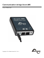
Communication bridge Xcom-MS
User Manual
Copyright © 2011 Studer Innotec SA - V1.0.1
Communication bridge Xcom-MS: User Manual
V1.0.1
Copyright © 2011 Studer Innotec SA
About the software
This document applies to the software version V1.4.0 or higher of the Xcom-MS. The software version number can be found using the menu "Information
on the system". The latest software version is available to download from the Studer Innotec website: "www.studer-innotec.com/support".
Legal Notice
The use of Studer Innotec SA devices is the responsibility of the customer in all cases. Studer Innotec SA reserves the right to make any modification
to the product without prior notice.
Product recycling
The Xcom-MS conforms to the European directive 2002/95/EC on hazardous substances and does not contain the following elements: lead, cadmium,
mercury, hexavalent chrome, PBB or PBDE.
To dispose of this product, please use the service for the collection of electrical waste and observe all applicable obligations according to the place
of purchase.
Studer Innotec SA
Xcom-MS
Table of Contents
1. Introduction ............................................................................................................................................... 7
1.1. The communication bridge Xcom-MS ........................................................................................... 7
1.2. Conventions ................................................................................................................................... 7
1.3. Warranty and liability ..................................................................................................................... 7
1.4. Safety precautions ........................................................................................................................ 8
2. EC declaration of conformity ................................................................................................................... 9
3. Dimensions ............................................................................................................................................. 10
3.1. Views of different sides with dimensions .................................................................................... 10
3.2. Exploded view ............................................................................................................................. 11
4. Installation .............................................................................................................................................. 12
4.1. Mounting ...................................................................................................................................... 12
4.2. Description of the front ............................................................................................................... 13
4.3. Connecting the Xtender communication bus .............................................................................. 13
4.4. Assigning of RS-485 addresses .................................................................................................. 14
5. Xcom-MS features ................................................................................................................................. 16
5.1. Status indication displayed on the RCC-02/-03 .......................................................................... 16
5.2. Management of charge cycles .................................................................................................... 17
6. Parameter settings ................................................................................................................................. 18
6.1. General information ..................................................................................................................... 18
6.2. User levels and accessibility ....................................................................................................... 18
6.3. BASIC SETTINGS {8000} ........................................................................................................... 18
6.3.1. Address of the MPPT selected to be on the display {8014} ............................................. 18
6.3.2. Charge cycles synchronization activated {8001} .............................................................. 18
6.3.3. Change the RS-485 identifier {8002} ............................................................................... 18
6.3.4. Restore default settings {8015} ........................................................................................ 18
6.3.5. Restore factory settings {8016} ........................................................................................ 18
6.4. BATTERY MANAGEMENT WITHOUT SYNCHRONIZATION {8003} ......................................... 18
6.4.1. Battery floating level {8004} ............................................................................................. 19
6.4.2. Maximum delay in floating {8005} .................................................................................... 19
6.4.3. Battery voltage level to start a new cycle {8006} ............................................................. 19
6.4.4. Battery absorption voltage {8009} .................................................................................... 19
6.4.5. Absorption time {8010} ..................................................................................................... 19
6.4.6. Battery temperature compensation {8011} ....................................................................... 19
6.4.7. Equalization allowed {8017} ............................................................................................. 19
6.4.8. Equalization voltage {8018} .............................................................................................. 19
6.4.9. Equalization time {8019} .................................................................................................. 19
6.4.10. Equalization interval {8020} ............................................................................................ 19
6.4.11. Equalization timeout {8021} ............................................................................................ 19
7. Troubleshooting ...................................................................................................................................... 20
8. Factory setting values ............................................................................................................................ 21
User Manual
V1.0.1
v
vi
V1.0.1
User Manual
Studer Innotec SA
Xcom-MS
1. Introduction
1.1. The communication bridge Xcom-MS
The communication bridge Xcom-MS makes it possible to integrate solar charge controllers from MorningStar,
the MPPT TriStar, with an Xtender system. It enables:
• system monitoring of the solar charge controller on the RCC-02/-03
• adjustment of the solar charge controller parameters using the RCC-02/-03
• data logging of operating data on SD cards
• synchronization of solar charge controller cycles with the inverter-charger
1.2. Conventions
Symbols
This symbol is used to indicate the presence of a dangerous voltage that is sufficient
to constitute a risk of electric shock.
This symbol is used to indicate a risk of material damage.
This symbol is used to indicate information that is important or which serves to optimize
your system.
1.3. Warranty and liability
Warranty and liability
During production and assembly, each Xcom-MS undergoes several controls and tests. These are carried out
in full respect of fixed procedures. Each Xcom-MS has a specific serial number allowing for a perfect follow-up
of the controls, in conformity with the specific data of every device. For this reason, it is highly important to
never remove the descriptive sticker bearing the serial number. The production, the assembly and the tests
of each Xcom-MS are entirely carried out in our factory in Sion (CH). The warranty of this product depends
upon the strict application of the instructions in this manual. The warranty period for the Xcom-MS is 5 years
from the date of manufacture.
Disclaimer of warranty
No warranty will be granted for damages due to handling, operation or actions that are not described in this
manual. Any damage caused by one of the following events is not covered by the warranty:
• Overvoltage on the device.
• Liquid in the device or oxydation due to condensation.
• Failures due to a fall or to a mechanical shock.
• Modifications made without the explicit authorization of Studer Innotec SA.
• Nuts or screws partially or insufficiently tightened during installation or maintenance.
• Damages due to atmospheric overvoltage (lightning).
• Damages due to transport or improper packaging.
User Manual
V1.0.1
7
Studer Innotec SA
Xcom-MS
• Loss of stickers or plates with origin marking.
Disclaimer of liability
Installation, commissionning, use and maintenance of this device can not be supervised by the company
Studer Innotec SA. For this reason, we do not accept any liability for the damages, the costs or the losses
generated either by an installation that is not conforming to the prescriptions, by a defectuous operation or
by a poor maintenance. The use of this device is under the responsibility of the end-user. This device is
neither designed nor guaranteed for the supply of life support applications or any other critical application with
potential risks for human beings or for the environment. We shall assume no liability for patent infringement
or other third party rights involved in the use of this device.
Compatibility
Studer Innotec SA guarantees the compatibility of the software updates with the hardware for one year,
starting from the date of purchase. The updates are no longer guaranteed beyond this date and a hardware
upgrade may be required. Please contact your reseller for any additional information on compatibility.
1.4. Safety precautions
Generalities
Do read carefully all safety instructions before proceeding with the installation and commissionning of the
device. Not respecting these instructions might constitute a lethal physical danger but can also damage the
functionnalities of the device. Therefore do keep this manual close to the device.
Strictly follow the local and national norms and regulations in force for any installation.
Warnings
• Wherever the installation, the person in charge of installation and commissionning must perfectly know the
safety measures and the prescriptions in force in the country. Therefore, all maintenance must be carried
out by a qualified staff.
• All components connected to this device must be conform to the laws and regulations in force. Persons
without a written authorization from Studer Innotec SA are forbidden to do any change, modification or
repair whatsoever. Regarding authorized modifications and replacements, only original components shall
be used.
• This device is meant to be used indoors and must under no circumstances be exposed to rain, snow or
any other humid or dusty environment.
8
V1.0.1
User Manual
Studer Innotec SA
Xcom-MS
2. EC declaration of conformity
The communication bridge Xcom-MS described in this manual meets the requirements specified in the following EC directives and norms:
• Low voltage directive 2006/95/EC: EN 60950:2005
• EMC directive 2004/108/EC: EN61000-6-1:2005 and EN61000-6-3:2006
• RoHS directive 2002/95/EC
CH - 1950 Sion, November 2011
Studer Innotec SA (R. Studer)
Studer Innotec SA contact details
Studer Innotec SA
Rue des Casernes 57
1950 Sion
Switzerland
+41(0) 27 205 60 80
+41(0) 27 205 60 88
[email protected]
http://www.studer-innotec.com
User Manual
V1.0.1
9
Studer Innotec SA
Xcom-MS
3. Dimensions
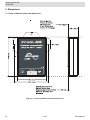
3.1. Views of different sides with dimensions
Figure 3.1. Views of different sides with dimensions
10
V1.0.1
User Manual
Studer Innotec SA
Xcom-MS
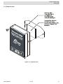
3.2. Exploded view
Figure 3.2. Exploded view
User Manual
V1.0.1
11
Studer Innotec SA
Xcom-MS
4. Installation
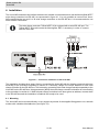
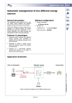
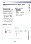
The Xcom-MS constitutes the interface between the Xtender communication bus and the MorningStar MPPT
solar charge controller bus RS-485, as represented in figure 4.1. It is only possible to connect one XcomMS to each Xtender bus and 1 to 30 solar charge controllers on the RS-485 bus. It is recommended to use
short RS-485 connections.
The solar charge controller TriStar MPPT-60 is equipped with a serial RS-485 port. The
TriStar MPPT-45 model needs the MorningStar RSC-1 accessory in order to connect
with the Xcom-MS.
Figure 4.1. Connection schematics of the Xcom-MS
The installation includes three steps. Start by connecting the Xcom-MS with the Xtender communication bus
according to the procedure explained in section 4.3. Secondly, assign one unique address to each solar
charge controller on the RS-485 bus. This is done by connecting each solar charge controller separately to the
Xcom-MS on the RS-485 bus. Using parameter {8002} the solar charge controller's identifier is set according
to the procedure in section 4.4. When all solar charge controllers have been given an address, connect them
to the RS-485 bus and the installation is finalized and ready to be used.
4.1. Mounting
The Xcom-MS can be mounted directly on any support by means of the supplied fixing plate or on a smooth
surface with a double-sided adhesive (see figure 3.2).
12
V1.0.1
User Manual
Studer Innotec SA
Xcom-MS
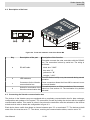
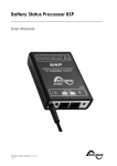
4.2. Description of the front
Figure 4.2. Front and isometric view of the Xcom-MS
Key
Description of the part
Description of the function
This cable connects the solar controllers with the RS-485
bus. The connection is done by serial bus. The wiring is
as follows:
a
RS-485 cable
• black wire: "GND"
• blue wire: "A"
• yellow wire: "B"
• red wire: "+12V"
This LED flashes briefly every two seconds during normal
operation.
b
LED indicators
c
Connectors for the Xtender These connectors allows the Xcom-MS to connect to one
communication bus
or several Xtender.
d
This switch turns on or off the termination of the communiSwitch for termination of the
cation bus. See section 4.3. The termination is by default
Xtender communication bus
activated.
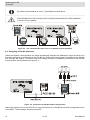
4.3. Connecting the Xtender communication bus
The devices in the Xtender range are equipped with a proprietary communication bus for data exchange,
configuration and updates of the system. The connection is made by linking the devices with the supplied
communication cables. This results in a bus in line where the termination must be activated on the devices
at both ends in order to obtain the configuration in figure 4.3.
Each device has a switch that allows to choose between open "O" or terminated "T". The devices at both
ends of the line must be set to "T". The others, receiving two communication cables, must be set to "O".
User Manual
V1.0.1
13
Studer Innotec SA
Xcom-MS
By default, the termination is set to T (terminated) on each device.
If the teminations are not corretcly set it may lead to erratic behaviour of the installation
or prevent it from updates.
Figure 4.3. The communication bus in line in an Xtender system (example)
4.4. Assigning of RS-485 addresses
Unlike the Xtender communication bus which automatically assignes the addresses, these will have to be
manually configured for all devices on the RS-485 bus. Begin by connecting the Xcom-MS with the Xtender
bus and start the system. Thereafter each solar charge controller is separately connected to the RS-485
communication bus as described in figure 4.4.
Figure 4.4. Connection for RS-485 address assignement
Start at the initial screen of the RCC-02/-03, use the buttons UP or DOWN to reach the configuration menu
of the MPPT Tristar settings, and then press SET.
14
V1.0.1
User Manual
Studer Innotec SA
Xcom-MS
To modify the parameter "Change the RS-485 identifier {8002}", use the buttons UP or DOWN to reach the
"BASIC SETTINGS" menu.
Press SET to enter the menu. Use the DOWN button to reach the parameter "Change the RS-485 identifier".
Press SET to change the value. The value will be displayed in inversed colours.
Use the UP and DOWN buttons to change the value into the correct address for the solar charge controller
connected to the RS-485. Confirm the new value by pressing SET. Wait five seconds for the new address to
be taken into account. If there is a problem with the new setting the screen of the RCC-02/-03 flashes red.
Disconnect the solar charge controller with a valid address and connect the next solar charge controller to
the RS-485. The address assignations can continue without having to leave the menu.
Once all solar charge controllers have been assigned an address, they can be interconnected as in figure 4.1.
To confirm that the right number of solar charge controllers have been detected, control the display value
"Number of MPPT" (see table 5.1). The Xcom-MS is ready to use.
User Manual
V1.0.1
15
Studer Innotec SA
Xcom-MS
5. Xcom-MS features
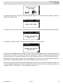
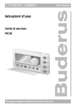
5.1. Status indication displayed on the RCC-02/-03
In installations with an Xcom-MS, the remote control RCC-02/-03 has an additional view, showing performance data of the solar charge controllers, see figure 5.1. On this display four values can be indicated.
Figure 5.1. Status indication displayed on the RCC-02/-03
It is possible to select which values to display. When in the view represented in figure 5.1, press SET. The
first field will then be selected. With the buttons UP and DOWN navigate to the field to configure. Use the
button SET to enter the menu of available values to display.
Select the value to display with the buttons UP and DOWN and confirm the selection with SET.
Press ESC to return to the initial view at any time.
These are the available values:
Name of the value
Label
Unit
Description
Sum of output power
Pout
W
Power injected in the battery from all solar charge controllers
Daily quantity of energy
Whd
Wh
The energy produced by all solar charge controllers
since midnight.
Average battery voltage
Ubat
Vdc
Battery voltage. This is an average of all the solar
charge controllers' values as they may have small
measuring differences.
Sum of battery currents
Ibat
A
Current injected into the battery from all solar charge
controllers.
Daily quantity of power transfer
Ahd
Ah
Ah capacity injected by all solar charge controllers
since midnight.
Number of MPPTs
nr
-
Number of MPPTs detected on the bus RS-485
Output power for the selected MPPT
Pou1
W
Power of the MPPT chosen in the setting {8014}. Only
visible in EXPERT mode.
Daily energy of the chosen MPPT
Whd1
Wh
Energy from the MPPT chosen in the setting {8014}.
Only visible in EXPERT mode.
Battery voltage of the chosen MPPT
Uba1
Vdc
Voltage measured by the MPPT chosen in the setting
{8014}. Only visible in EXPERT mode.
Battery current of the chosen MPPT
Iba1
Adc
Current measured by the MPPT chosen in the setting
{8014}. Only visible in EXPERT mode.
Voltage of the solar panels connected with
the chosen MPPT
Usol
Vdc
Voltage of solar panels connected with the MPPT chosen in setting {8014}. Only visible in EXPERT mode.
Daily power transfer of the chosen MPPT
Ahd1
Ah
Power transfer since midnight by the MPPT chosen in
the setting {8014}. Only visible in EXPERT mode.
Table 5.1. Available values for the MPPT TriStar view
16
V1.0.1
User Manual
Studer Innotec SA
Xcom-MS
5.2. Management of charge cycles
When the parameter {8001} "Charge cycles synchronization activated" is set to "Yes", the Xcom-MS receives
the cycle voltage setpoint for the inverter-charger(s) from the Xtender communication bus. The Xcom-MS tranfers the information to the solar charge controllers using the RS-485. In case of failure of the inverter-chargers
or loss of connection, the solar charge controllers return to independent mode using their own parameter set.
When the parameter {8001} is set to "No" the solar charge controllers use their own battery cycle which is
synchronised with the parameter set in the Xcom-MS. This is the default behaviour.
The internal set of paramenters in the solar charge controllers is constantely being synchronised with the
set of parameters of the Xcom-MS which can be found in the menu {8003} "Battery management without
synchronization". These parameters can be modified using the RCC-02/-03. If a parameter is changed the
synchronisation can take up to one minute and may generate a restart of the solar charge controllers.
The solar charge controller's DIP switches should be configured in "Custom" position
(that is with 4,5,6 set to ON) in order for its internal parameter set to be taken into
account. Otherwise the DIP configuration will be used.
User Manual
V1.0.1
17
Studer Innotec SA
Xcom-MS
6. Parameter settings
A complete list of available parameters can be found in chapter 8.
6.1. General information
The configuration is carried out on the RCC-02/-03 by means of the MPPT TriStar parameter menu.
6.2. User levels and accessibility
The functions described below are available at EXPERT level. Depending on the selected user level, all
of these functions may not be accessible. Do refer to the chapter "RCC remote control settings" for more
information regarding the different user levels.
6.3. BASIC SETTINGS {8000}
The parameters for a basic setup of the MPPT TriStar are found in this menu.
6.3.1. Address of the MPPT selected to be on the display {8014}
On the RCC-02/-03 display, illustrated in figure 5.1, it is possible to show the combined values of all solar
charge controllers but also the values of one specific device. This parameter is used to select the RS-485
identifier of the specific solar charge controller which values will be shown on the display.
6.3.2. Charge cycles synchronization activated {8001}
When this parameter is set to "Yes", the solar charge controllers are driven by the Xcom-MS to follow the
same charge cycle as the inverter-charger(s) (see section 5.2).
When activating this parameter {8001}, it is essential to check that the Xtender parameter {1158} "End of absorption triggered with current" is set to "No". This in order to
achieve an optimal battery charge curve.
6.3.3. Change the RS-485 identifier {8002}
This parameter is used to change the RS-485 identifier of a solar charge controller single connected on the
RS-485 bus. The procedure is described in section 4.4.
If several solar charge controllers are connected on the RS-485 bus during the change
of this parameter, they will all be assigned the same address. This will lead to collisions
during operation putting the communication bus out of order. A reassignement of the
addresses will solve this problem.
6.3.4. Restore default settings {8015}
Use this parameter to restore the initial settings of the Xcom-MS.
If your installer has changed some settings at "installer" level while commissioning your
installation, this function restores his settings and not the default factory settings.
6.3.5. Restore factory settings {8016}
This feature restores all factory settings, including the factory values, restrictions and user levels. This paramenter is only accessible at "installer" level.
6.4. BATTERY MANAGEMENT WITHOUT SYNCHRONIZATION {8003}
18
V1.0.1
User Manual
Studer Innotec SA
Xcom-MS
This menu contains a parameter set for the battery cycle, which is copied to the solar charge controllers as
described in section 5.2. Further information on these parameters can be found in the solar charge controller
documents.
6.4.1. Battery floating level {8004}
Floating voltage of the solar charge controllers.
6.4.2. Maximum delay in floating {8005}
Time below floating voltage to restart a new cycle.
6.4.3. Battery voltage level to start a new cycle {8006}
The voltage level to reach in order to start a new cycle.
6.4.4. Battery absorption voltage {8009}
Voltage value for the absorption cycle.
6.4.5. Absorption time {8010}
Duration of the absorption phase.
6.4.6. Battery temperature compensation {8011}
A factor used to correct the battery cycle voltage. Each solar charge controller should be provided with an
individual battery sensor.
6.4.7. Equalization allowed {8017}
This parameter is used to define if the equalization phase is allowed.
6.4.8. Equalization voltage {8018}
Equalization voltage.
6.4.9. Equalization time {8019}
Time during which the equalization voltage is maintained.
6.4.10. Equalization interval {8020}
Number of days in between two equalization phases.
6.4.11. Equalization timeout {8021}
Maximal time spent above absorbation voltage attempting an equalization.
User Manual
V1.0.1
19
Studer Innotec SA
Xcom-MS
7. Troubleshooting
To ensure a smooth running of the system it is important to set it up in accordance with the installation manuals
from Studer Innotec SA and MorningStar. If at commissioning the system is not operational, please check
your installation's compliance with the requirements stated in the manuals mentionned above.
If your system still isn't working, please check the following points:
1. Check the position of the programmation switches on the MPPT TriStar solar charge controllers. The
switches 4, 5 and 6 should be set to "ON".
2. Check that the software update of the Xtender system was carried out in accordance with the official
procedure. The latest software version of your installation is available on the SD card delivered with the
Xcom-MS or can be downloaded from our website: http://www.studer-innotec.com.
3. Check the wiring and that the communication cable RS-485 is correctly inserted in the connection compartment.
4. Check that the address assignement procedure described in section 4.4 has been followed.
5. Check that the battery voltage is visible on the TriStar solar charge controller terminals.
6. The TriStar solar charge controller can function without connection to the Xcom-MS. When the RS-485
connector is disconnected, the TriStar solar charge controller will stop automatically. It has to be disconnected from the battery and then reconnected in order to function in autonomous mode. On the contrary,
only one solar charge controller without battery connection will put the RS-485 bus out of order.
7. If the Xtender installation is disconnected (for example by disconnecting the communication cable) or shut
off, the TriStar solar charge controller will automatically return to an independant mode and will continue
to charge and maintain the battery.
8. When the synchronisation is activated {8001}, the TriStar's green LED is normally flashing once every
second (as when it is in independent absorption mode). With the synchronisation activated, it is also possible to indicate the charge phase in one of the two battery information fields on the RCC-02/-03 remote
control's Xtender screen.
20
V1.0.1
User Manual
User Manual
V1.0.1
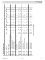
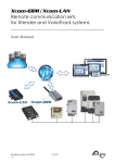
8011
8017
8018
8019
8020
8021
Basic
Basic
Basic
Basic
Basic
8006
Basic
Basic
8005
Basic
8010
8004
Basic
Basic
8003
Basic
8009
8016
Inst.
Basic
Restore default settings
8015
Basic
Equalization timeout
Equalization interval
Equalization duration
Equalization voltage
Equalization allowed
Battery temperature compensation
Absorption duration
Battery absorption voltage
Battery voltage level to start a new cycle
Maximum delay in floating
Battery floating level
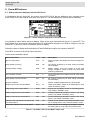
BATTERY MANANGEMENT WITHOUT SYNCHRONIZATION
Restore factory settings
Change the RS-485 identifier
Expert 8002
hours
days
hours
Vdc
No/Yes
mV/°C/
cell
hours
Vdc
Vdc
hours
Vdc
No/Yes
Unit
3
28
1
15.1
No
-5
2
14.4
12.5
2
13.6
S
S
0
No
1
1
1
.2
13
No
-8
.2
9.5
9.5
.2
9.5
S
S
0
No
0
Facto- Min
ry
12 V
50
365
10
18
Yes
0
18
18
18
18
18
S
S
30
Yes
30
Max
Table 8.1. Factory setting values
Charge cycles synchronization activated
8001
Basic
BASIC SETTINGS
Address of the MPPT selected for the display
8000
Basic
Parameter
Expert 8014
User
ref.
Level
8. Factory setting values
3
28
1
30.2
No
-5
2
28.8
25
2
27.2
S
S
0
No
1
1
1
.2
26
No
-8
.2
19
19
.2
19
S
S
0
No
0
Facto- Min
ry
24 V
50
365
10
36
Yes
0
18
36
36
18
36
S
S
30
Yes
30
Max
3
28
1
60.5
No
-5
2
57.6
49.9
2
54.5
S
S
0
No
1
1
1
.2
52.1
No
-8
.2
37.9
37.9
.2
37.9
S
S
0
No
0
Facto- Min
ry
48 V
50
365
10
72
Yes
0
18
72
72
18
72
S
S
30
Yes
30
Max
Studer Innotec SA
Xcom-MS
21
Studer Innotec SA
Rue des Casernes 57
1950 Sion
Switzerland
+41(0) 27 205 60 80
+41(0) 27 205 60 88
[email protected]
http://www.studer-innotec.com