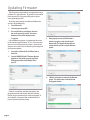
1
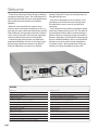
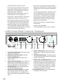
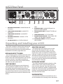
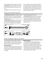
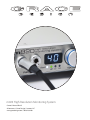
m920 High Resolution Monitoring System
Owner’s Manual Rev B
all contents © Grace Design / Lunatec LLC
www.gracedesign.com / 303.823.8100
Welcome
Thanks for purchasing the Grace Design m920 high
resolution monitoring system. The m920 represents a
powerful combination of pristine audio performance,
robust mechanical construction and steadfast
reliability.
While we strive to build all our products to be
simple to setup and intuitive to operate, we do suggest that you spend a little time familiarizing yourself
with the features and operational functions outlined
in this manual. Doing this will make your experience
with the m920 more productive and enjoyable.
In the event that you encounter any technical or
operational difficulties with this or any Grace Design
product, please feel free to contact us at 303-8238100. Our office hours are from 9 to 5, Monday
through Friday, MST. Or you can email questions to:
[email protected].
Also, please remember to visit our website www.
gracedesign.com for the latest Grace Design product information, owner’s manuals and technical
documents.
Grace Design has been building superlative quality
professional audio products since 1995. The technology developed for the m920 has evolved through a
process of extensive listening, testing and careful refinement. Regardless of what type of monitoring you
do, your m920 will faithfully serve as an invisible link
between your source audio and your headphones
or speaker systems. We sincerely hope it helps you
achieve a new level of excellence in your work!
CONTENTS
Welcome2
Important Safety Information
3
Safety Marking Symbols
3
m920 Key Features
3
m920 Front Panel Controls / Features
4
m920 Rear Panel
5
Unpacking and Installing your m920
5
Powering up the m920
6
Input Connections
6
Output Connections
7
Selecting an Input Source
7
m920 USB / Computer Audio Configuration
8
Operating the Headphone and Line Outputs
8
page 2
About s-lock™
9
About x-Feed (crossfeed)
9
Accessing And Using The Setup Menu
10
Grace Design IR Remote Control Operation
15
Apple IR Remote Control Operation
16
Fixed DAC Output Configuration
17
Updating Firmware
18
Block Diagram
20
Specifications21
Cleaning and Maintenance
22
Warranty Information
22
Manual Revisions
23
Important Safety Information
• Pollution Degree 2
GENERAL
• Indoor use only
• Ordinary Protection: This equipment should not
be exposed to dripping or splashing.
• Avoid placing objects filled with liquids, such as
vases or glasses, on this equipment.
• Installation (Over voltage) Category II for transient overvoltages.
• Maximum Relative Humidity: <80%
• Operation temperature range: 10 °C to 40 °C
• Class I Equipment (grounded type)
• Storage and transportation temperature range
–40 °C to 70 °C
• Electrical rating: 100-120/220-240V~ 50-60Hz
25W
• Maximum altitude: 3000m (9843 ft)
• Mains supply voltage fluctuations are not to
exceed ±10% of the nominal supply voltage.
• Weight: 2.3kg (5lbs)
• Equipment suitable for continuous operation
Safety Marking Symbols
CAUTION: READ ACCOMPANYING
DOCUMENTS
This symbol, located on the equipment and in this manual, refers to
important instructions. Read this
manual thoroughly before operating
this equipment.
SERVICE INFORMATION
The Grace Design m920 contains no user serviceable components. Contact Grace Design for repair
and upgrade information. In the event that your
Grace Design m920 needs to be returned to the factory, contact us for a return authorization number.
WARNING: ELECTRICAL SHOCK HAZARD
This symbol, located on the equipment
and in this manual, indicates the potential for electrical shock hazard.
m920 Key Features
• Stereo analog inputs - balanced (+4dBu) XLR and
unbalanced (-10dBv) RCA.
• AES and S/PDIF playback of up to 192kHZ / 24bit
PCM as well as DSD64 playback via DoP
• Ultra low distortion 32-bit /384khz Sabre DAC
accepts stereo digital input sources in AES3,
S/PDIF, TOSLINK (optical) and USB formats with
auto sample rate detection and digital de-emphasis filter
• New dual-stage wide lock range PLL for improved jitter rejection on non s-locked sources
• User configurable DAC filter response for PCM
and DSD playback
• Two sets of line level outputs provided via RCA
(unbalanced) and ¼ TRS jacks (balanced) for connection to stereo monitors
• USB for playback of up to 384kHz / 32 bit PCM as
well as DSD64 and DSD128 playback via DoP
• Third generation s-Lock™ dual stage PLL (phase
lock loop) circuitry for the ultimate in low jitter
clocking and sonic integrity
• RCA line outputs can be configured for variable
or fixed DAC output mode for operation as a
page 3
standalone digital to analog converter
• High current transimpedance output amplifier
design drives 8 ohm loads. The m920 was specifically designed with low impedance headphones
in mind
• Front panel rotary encoder provides precision
level control of both headphone and the line
output levels. Level adjustments are made in
0.5dB steps within a 95dB range
• Only the highest quality 0.5% metal film resistors
are used throughout and there are no electrolytic capacitors in the signal path. Sealed gold
contact relays are used for all signal switching
• 0.05dB channel level matching to ensure true
stereo balance at any monitoring level
• Large, white 7-segment display is used to show
headphone and stereo main output levels
• Infrared remote control for level control, left/
right balance, mute and more when using the
optional remote control unit
• New X-feed (crossfeed) simulates the acoustics
of a loudspeaker listening environment which
can significantly improve imaging while reducing listening fatigue when using headphones.
This feature employs carefully designed signal
cross-feed, filtering and delay circuits to simulate
HRTF (head related transfer functions)
• Apple IR remote control is supported with optional pairing
• USB firmware upgradability
• 5 Year transferable warranty on parts and labor
m920 Front Panel Controls / Features
resolution
920 high
monitoring system
S/PDIF
sLock
xfeed
HP L1
PHONES
10
1
9
8
L2
VOLUME
7
ILLUMINATED POWER SWITCH illuminates white
when unit is powered on.
2
3
4
5
6
page 4
DSD
ROTARY INPUT SELECTOR SWITCH selects between all available inputs.
S-LOCK™ INDICATOR LED illuminates when sLock™ is active.
SAMPLE RATE INDICATOR LEDS auto sample rate
detection from selected digital input source.
LEDS indicate the base sample rate with the appropriate multiplier for 2x, 4x and 8x rates.
DSD INDICATOR LED auto DSD detection from
the selected digital input source
VOLUME / EDIT ROTARY ENCODER This stepped
rotary encoder controls the selected output
level in .5dB increments. This encoder is also
used to adjust other settings found in the setup
menu.
6
5
AES
4x
2x
48
44
TOS
8x
USB
BAL
FS
4
INPUT
3
2
UNBAL
GRACE DESIGN
1
OUTPUT SELECTION LEDS These LEDS indicate
which output is currently selected for volume
control.
8 CROSSFEED INDICATOR LED Crossfeed circuitry is
user activated in the setup menu or via optional
wireless remote control.
9 OUTPUT LEVEL / SETUP MENU DISPLAY This white
2 digit display shows the current relative output
level values based on the position of the main
level rotary encoder. The range of this display is
0 to 99. Note the decimal represents a +0.5dB
increment. This display is also used to give the
user information in the setup menu.
10 HEADPHONE OUTPUTS Two stereo headphone
output jacks wired in parallel.
7
m920 Rear Panel
PUSH
USB IN
PUSH
L
PUSH
S/PDIF IN
1
2
LINE OUT 2
LINE OUT 1
UNBAL IN
TOSLINK IN
10
1
9
8
7
5
UNBALANCED ANALOG INPUT standard RCA
7
UNBALANCED LINE OUTPUT standard RCA
8
connectors.
4
BALANCED LINE OUTPUT standard 1/4” TRS
connectors.
5
AES DIGITAL INPUT use 110 Ohm balanced
3
2
R
3
BAL IN
L
1
cable.
6
connectors.
3
4
BALANCED ANALOG INPUT standard female XLR
connectors.
2
R
1
2
3
AES3 IN
6
1
2
3
9
10
USB DIGITAL INPUT standard USB type A -totype B mini cable included.
TOSLINK DIGITAL INPUT standard TOSLINK optical cable.
S/PDIF DIGITAL INPUT use 75 Ohm cable.
AC LINE VOLTAGE SELECTOR selects beteen 100120VAC and 220-240VAC operation.
AC LINE INPUT MODULE standard 3 prong AC
cable included.
Unpacking and Installing your m920
The m920 is shipped in one box which contains the
m920 unit, an AC power cord, a USB cable, a small
plastic bag containing four hand-threaded machined
metal feet and a warranty registration card.
OPEN AND INSPECT THE BOX
Open all shipping boxes, carefully remove the m920
and put it aside. Before you go any further, check to
make sure the above listed components are included
with your shipment. If you believe something is
missing, contact your Grace Design dealer and they
will make sure you’re taken care of.
SAVE YOUR BOX!!
We strongly encourage you to save the box and
shipping materials supplied with your m920. They
are specially designed to properly protect these
valuable components, and in the unlikely event that
you need to return them for service, only these OEM
shipping materials can ensure their safe return to our
factory.
REGISTER YOUR UNIT!
We strongly urge you to register your unit with
Grace Design. We provide a limited 5 year transferable warranty on all of our products, but if you
register your system, it’s easier for us to help you if
necessary. So please take a few minutes to complete
the enclosed warranty registration card and mail it
in, or you can simply go to the warranty registration
form on our web site. We do not share your information with anyone. Thank you!
INSTALLING THE FEET
The m920 is designed to either be placed on a flat,
stable surface in your studio or listening environment, or be rack mounted. If you don’t plan to rack
mount your m920, first install the 4 supplied metal/
rubber feet. Simply thread the supplied feet by hand
into the 4 vacant threaded holes in each corner of
the underside of the m920.
RACKMOUNTING
For rack mount installation, the m920 chassis has a
#10-32 threaded insert mounting hole on the bottom
page 5
towards the back. Two m920’s can be mounted side
by side in a standard 1U rack tray. Use the supplied
#10-32 x 3/8” machine screw. Do not use a screw
longer than 3/8”.
Powering up the m920
POWER CONNECTIONS
AC POWER CORD
The disconnect device for the m920 system is the
mains plug or the appliance coupler on the power
supply cord. The disconnect device must remain
accessible and operable. The power supply cord supplied with the m920 must be connected to a mains
outlet with a protective earthing connection.
a
outlet.
CHECK LINE VOLTAGE SETTINGS
LOW VOLTAGE DETECTION
The IEC power entry module has been set from the
factory to operate at the voltage required for your
part of the world. However, it’s important to doublecheck this in order to ensure no damage will come
to the unit if power is applied and the setting is
incorrect.
LINE VOLTAGE SELECTOR
To change the line voltage, remove the AC power
chord from the power inlet then use a small screwdriver to pry the fuse carrier out. Remove both fuses
from the fuse carrier and replace with the proper
value fuse from the fuse chart below. Carefully
remove the grey colored fuse holder and re-insert
it into the fuse carrier with the proper line voltage
showing through the small window. Note that time
delay or “slow blow” fuses are required.
Voltage and Fuse information
CAM SETTING
110V~
220V~
LINE VOLTAGE
100-120V~
220-240V~
FUSE VALUE
250V~ T 250mA L
250V~ T 125mA L
fuse value table
Connect the supplied AC cord to the iec
power entry module on the rear panel
of the m920. For safety, it is recommended that the cable be connected to
grounded
The m920 will automatically detect a low line voltage condition. In the event that line voltage drops
below 85 VAC (for 100 -120 VAC) or 170 VAC (200
– 240VAC), the m920 will switch into low voltage
detection mode. In this mode both headphone and
line outputs are muted, and the 7 segment led will
begin to flash. The m920 will automatically return to
the previous operating state when proper line voltage is restored.
POWER-UP SEQUENCE
The m920’s headphone outputs are protected
from any popping when the unit is turned on or off.
However, if you are using the line outputs, observing proper power sequencing is recommended to
avoid any potential popping in your speakers. Before
powering up your m920, make sure your monitor
speakers or power amps connected to your monitors are turned OFF. Once the m920 and the rest of
your audio system are powered up, then turn on the
power to your speakers or amplifiers. When powering
down, first power OFF your speaker system and / or
power amps and then power down the m920. Turn
power amps on last, turn them off first!
Input Connections
The input / output / interface connections highlighted earlier in this manual are detailed below.
Please contact us if you have any questions regarding
cable terminations or pinout specifications.
BALANCED ANALOG INPUTS The balanced stereo analog input is provided via female XLRs. Connection is
made using standard balanced XLR cables. This input
is wired pin 1 shield, pin 2 positive pin 3 negative.
UNBALANCED ANALOG INPUT This stereo input is
page 6
provided for interfacing with consumer level (-10dBv)
unbalanced analog sources. Connections are made
using standard RCA cables.
AES3 DIGITAL INPUT The stereo AES3 input is provided via one female XLR connector. This conforms
to the AES3 standard. Use of high quality 110 Ohm
balanced cable is highly recommended.
S/PDIF COAXIAL INPUT Standard coaxial stereo
digital input. The input impedance is 75 Ohms. Use a
to a host computer. Use a USB 2 (high speed) type
A -to- type B mini cable (included with your m920).
The type A connector is to be plugged in to the HOST
PC and the type B mini connector is to be used with
the m920 input. Due to the very high speed operation of this interface we recommend a 6ft (1.8 meter)
maximum length for this cable.
quality 75 Ohm cable for connections to this input.
TOSLINK INPUT Standard stereo optical input connector for use with consumer devices. Use a standard TOSLINK optical cable for connections to this
input.
USB INPUT The stereo USB input for connection
Output Connections
STEREO HEADPHONE OUTPUTS Headphone outputs
are provided via two ¼” TRS (Tip, Ring, Sleeve) jacks.
These outputs are wired in parallel. Connection to
headphones should be made using standard ¼” TRS
stereo connectors.
UNBALANCED LINE OUTPUTS A stereo pair of unbalanced line level outputs are provided via two RCA
jacks. These outputs should be connected to powered speakers, a preamplifier, or power amplifiers
Balanced Output 1/4” TRS
using standard unbalanced RCA cables.
BALANCED LINE OUTPUTS A stereo pair of balanced
line level outputs are provided via two ¼” TRS jacks.
These outputs should be connected to powered
speakers, a preamplifier, or power amplifiers using
standard balanced cables. Connection to an unbalanced input is also possible. See diagrams below for
proper termination.
Balanced Input XLR
SLEEVE
TIP
pin 2
RING
pin 1
pin 3
Unbalanced Input RCA
Balanced Output 1/4” TRS
TIP
RING
SLEEVE
RING IS OPEN
HOT
GND
SHIELD
Selecting an Input Source
The m920 allows for selection from a variety of
analog and digital input sources. The rotary input
selector switch is used to choose the input source for
both the headphone amplifier and line outputs.
ANALOG INPUTS The m920 provides both balanced and unbalanced
stereo inputs. To select either of these analog inputs,
rotate the input selector to the desired input. When
an analog input is selected, the m920’s internal DAC
is turned off.
DIGITAL INPUTS
The m920 provides the following digital input
sources: AES3, S/PDIF, TOSLINK and USB. The AES3
and S/PDIF inputs support PCM audio data with
sample rates from 44.1kHz to 192kHz / 24 bit as well
as DSD64 via DoP. The TOSLINK input supports PCM
audio data with sample rates 44.1kHz to 96kHz /
24bit. The USB input supports PCM audio data with
sample rates from 44.1kHz to 384kHz / 32bit in addition to DSD64 and DSD128 via DOP.
page 7
m920 USB / Computer Audio Configuration
ASYNCHRONOUS AUDIO
The asynchronous mode USB converter in the m920
represents a significant improvement over any previous type of USB DAC. Previously, a USB DAC worked
under standard adaptive mode USB audio, which
means the DAC’s clock would have to sync to the
non-audio related computer USB buss master clock.
As you can imagine, the computer has a lot else to
do, so the incoming clock signal to which the DAC’s
clock would have to sync was not ideal and would
result in unwanted jitter.
With asynchronous mode USB, the USB DAC becomes the master to which the computer’s USB
buss gets synced. So the computer is now synced
to a crystal-based audio clock signal and the system
works with dramatically lower jitter. No phase-lock
loop or sample rate conversion is necessary, which
means bit-perfect playback from a computer with
zero interface induced jitter. In addition, the USB
port ground is completely isolated from the m920
audio ground. This eliminates the possibility of noisy
computer grounds inducing any noise or impurity in
the m920 audio circuits.
COMPUTER AUDIO REQUIREMENTS
Regardless of the type of computer you will use to
playback audio from, it must have at least one available USB port. The m920 ships with a standard USB
type A to type B mini cable. The type A connector
plugs in to the computer and the type B mini connector to the USB m920 input.
The m920’s asynchronous mode USB DAC supports
standard driverless operation on MAC to 384kHz and
on PC to 96kHz. For sampling rates above 96kHz, PC
users will need to download and install a free driver
on their computer. This driver can be found on our
website - http://www.gracedesign.com/support/support.htm
Driverless operation basically means ‘plug and
play’. The m920 will automatically show up in your
computer’s list of supported audio devices as ‘Grace
Audio Device’. In most cases, simply choose that as
your audio playback device and the system will work.
Different operating systems and audio players will
pose their own set of complications in setting up
the m920 as the audio playback device. In the event
that ‘plug and play’ operation does not occur, you
will need to look at some specific setup variables for
your player and OS. In this case, we will direct you to
a very well written and comprehensive document by
our friend and colleague Charles Hanson from Ayre
Acoustics. http://www.ayre.com/usb.htm
This is an invaluable resource for computer/USB
audio setup information for most current operating systems, and we strongly urge you to familiarize
yourself with the information pertaining to your specific OS. In the event that you have any setup issues
which aren’t addressed by these resources, feel from
to contact us directly at 303.823.8100 M - Friday 9 – 5
MST, or you can email our service department [email protected].
Operating the Headphone and Line Outputs
Both the headphone and the line outputs feature
precision level control from the front panel rotary encoder. Each output can be completely independent
of the other in terms of level and balance control (see
the setup menu section for further description of this
feature).
The output selection indicator LED’s show which
output is currently under control by the volume control. To toggle the output control selection, simply
press and release the rotary level encoder. You will
see the selection indicator change. Two different
modes can be used for toggling through each output
level. The first (L1) has the 2 line outputs ‘ganged’ together and they are controlled in unison, the second
page 8
(L2) is a ‘round robin’ type, where the line outputs are
controlled independently of each other. More information on these two modes is found in the set up
menu section of this manual.
The volume encoder is used to adjust the level of
both the headphone and line level outputs independently. The level of the currently selected output
is displayed in the 7-segment display. Turning the
encoder clockwise increases the output level and
counter-clockwise decreases it.
The m920 features an extremely high precision
analog volume control. Step size is 0.5dB and channel matching is within 0.05dB for all settings. Also,
embedded within the volume control architecture is
a 3 stage acceleration curve. The encoder has 24 positions. Turning it one revolution slowly will result in
a change of 12dB (24 x 0.5dB). As the rotation speed
increases, each step goes from 0.5dB to 2.0dB and
then to 4.0dB. This allows not only precise control but
also convenience when large volume changes are
desired.
Any changes made are reflected in the 7-segment
display. Level range is from 0.0 to 99.5. NOTE: The
least significant digit’s decimal point (.) is used to
indicate +0.5dB increments.
About s-lock™
The improved s-Lock™ is our proprietary PLL (Phase
Lock Loop) circuitry that has been specifically developed for the m920 and its big brother the m905 .
When using the TOSLINK, S/PDIF, or AES3 digital
inputs, the digital audio stream contains an embedded clock that can contain various forms of jitter. The
s-Lock PLL will lock to this clock source and provide
an extremely stable and ultra-low jitter clock to run
the DACs.
s-Lock™ is a crystal-based PLL used for regenerating
the incoming digital clock. The crystals used have extremely low intrinsic jitter and are capable of locking
to sample rates of up to 192kHz. When the digital input selected for the DAC is active, the s-Lock circuitry
automatically captures the incoming recovered
clock from the AES3, S/PDIF, or TOSLINK connectors.
Once phase-lock with the incoming signal has been
achieved, the DAC’s, which have been running off the
original clock, are switched to run off the ultra-low
jitter s-Lock system clock. If at any time s-Lock is lost
or not achieved, the DAC’s are run off the original
clock. The s-Lock system can effectively lock to input
sample rates of 44.1kHz or 48kHz +/- 5Hz, 88.2kHz or
96kHz +/- 10Hz and 176.4kHz or 192kHz +/- 20Hz.
If the incoming digital audio signal clock frequency
is outside of these tolerances, the s-Lock circuit
will not lock and the s-Lock indicator on the m920
will extinguish. The m920 features a second PLL in
addition to the s-Lock circuit. This circuit provides
a wide bandwidth lock range and achieves excellent recovered clock jitter performance even when
s-Lock is inactive. Note that in USB mode, the m920
is the clock master so there is no need to “lock” to an
incoming signal.
About x-Feed (crossfeed)
When listening to loudspeakers in a room, your
left ear hears sound primarily from the left speaker
(and vice versa) but also receives a signal from the
right speaker at a lower level and with some time
delay compared to the right ear. As well, the right
speaker sound that reaches the left ear does not
have a flat frequency response as the sound waves
have traveled around the shape of your head before
reaching your left ear. The brain uses delay, level and
frequency response characteristics to process the
location of a sound and hence, create an aural image.
When listening through headphones, each ear only
hears the sound from one transducer and the mixing of signals between the ears does not exist. In this
situation the brain is left without many of the psycho
acoustic clues required to generate a properly distributed image and an accurate sound stage. The result
is that instruments seem to cluster in the far left, far
right or center of your head. Since the vital clues are
absent, the brain has a difficult time deciding how
to process the sounds coming from the headphone,
which can result in listening fatigue when listening
for extended periods of time.
The m920 contains new crossfeed circuitry which
electronically simulates the signal crossfeed that
occurs in a real acoustic space and helps the brain establish instrument locations across the entire sound
stage. While it is difficult to perfectly model the
very complex level, delay and frequency response
characteristics of the head, the crossfeed circuitry in
the m920 gives the brain some of the basic clues it
needs and the result is a very pleasing simulation of
an acoustic space while maintaining the tonality and
balance of the original source.
page 9
Accessing And Using The Setup Menu
The m920 features a number of useful functions
that can be accessed and adjusted entering and navigating the setup menu.
To access the m920 setup menu, simply press and
hold the front panel encoder knob for 3 seconds.
Once the m920 has entered the setup menu, you will
see the 7- segment display change to reflect the currently activated setup menu item.
To navigate through the available setup menu
items, simply rotate the encoder knob, which will
scroll you through the available menu items, either
clockwise or counter-clockwise. Once the last item is
reached, continuing to rotate will loop you back to
the first.
To exit the setup menu at any time, press and hold
the encoder knob for 3 seconds. The 7-segment
display will switch back to the current output level
once the setup menu has been exited. Note: When
the setup menu is exited, the last mode you were in
will be the first mode activated the next time you
enter the setup menu. This allows quick access to the
parameter you are currently adjusting.
The setup menu is also accessible by the optional
m920 infrared remote control. Please refer to the
‘Remote Control Operation’ chapter for a detailed
description of how this works.
Following is each available setup menu option, in
the sequence they appear.
BALANCE MODE
This provides individual left / right balance control
of 6dB in 0.5dB increments for each available output
(headphone, Line 1 and Line 2). To program balance
settings:
• Push and hold the rotary encoder to enter the setup
menu, then rotate the encoder until you reach the
balance settings, which are indicated as: bH for
headphones, b1 for line output 1 and b2 for line output.
• When you have reached the output you wish to adjust,
push the encoder again to enter the balance setting.
• When no balance offset has been made, both the left
and right speaker symbols are shown in the 7-segment
display.
page 10
• Turning the rotary encoder clockwise results in a
balance adjust to the right. This will be indicated by
the right facing speaker symbol changing to the
corresponding balance offset value.
• Turning the rotary encoder counter-clockwise results in
a balance adjust to the left. This will be indicated by the
left facing speaker symbol changing to the
corresponding balance offset value.
With each detent of the volume control the m920
alternates between adding .5dB to one channel and
then subtracting 0.5dB from the other. This continues
until one channel is 3dB louder and the other is 3dB
quieter.
To store your balance setting for the selected output, push and hold the encoder. This will then send
you out of the setup menu and back to the main
level control screen.
The m920 stores all three balance level settings in
non-volatile memory and recalls these upon each
power up.
POWER UP LEVEL
This feature allows the user to save specific level
settings for each output as the default power up
level. While default levels are set to 0 at the factory,
you may want to have the unit always power up at
a specified level other than the default. To program
power up level settings:
• Push and hold the rotary encoder to enter the setup
menu. Now rotate the encoder until you reach the
power up level settings, which are indicated as: PH for
headphones, P1 for line output 1 and P2 for line output.
• When the m920 is in L1 mode (both line outputs
ganged together for volume control) the preset level
for the unbalanced line out (L1) will be used for both
sets of outputs.
• When you have reached the output that for which you’d
like to enter the power up level, push the encoder again
to display the current power up level.
• From here you can rotate the encoder to adjust the
power up level.
• From here, you can either push and hold to
immediately store the level, which will then send you
back to the main level control screen. Or, push the
encoder once (without holding) to exit back to the first
level of the setup menu, from where you can select and
adjust another power up level. Note: This option does
not store the power up level until you push / hold and
exit back to the main level control screen.
OUTPUT TOGGLE LOCK OUT MODE
Situations may exist when you need to lock the
output level select toggle function of the encoder to
prevent inadvertent switching. This mode is reset to
OFF whenever the m920 is power cycled.
Once this mode is enabled, pressing and releasing the encoder button no longer toggles the m920
through the 3 available outputs. Pressing and holding the encoder button will still allow the user to
enter the setup menu. This mode is reset to OFF
whenever the m920 is power cycled. To activate this
feature:
• Push and hold the encoder to enter the setup menu.
Now rotate the encoder until you reach the output
toggle lock mode, indicated by the OL symbol in the
7-segment display.
• Pushing the encoder once turns the this mode ON,
which is indicated by the decimal points illuminating in
the O.L. symbol.
• Turning the rotary encoder counter-clockwise turns this
mode OFF, which is indicated by the OL symbol without
the decimal points.
SELECTING USB CLASS 1 OR USB CLASS 2
This setting determines the whether the m920 functions as a USB class 1 or class 2 audio device. USB
class 1 audio mode supports playback of audio files
with sample rates up to 96kHz. For playback of files
above 96kHz, you will only need to use the setting
for USB class 2 Audio. For complete details on how
to configure your computer for playback over USB,
please refer to the ‘computer setup’ chapter of this
manual. To change this setting:
• Push and hold the rotary encoder to enter the setup
menu. Now rotate the encoder until you reach the USB
class select menu item, indicated by either the U1 or
the U2 symbol in the 7-segment display.
• Push and release the encoder to toggle between and
select either mode. U1 indicates class 1 USB operation,
while U2 indicates class 2 USB operation.
• Push and hold the encoder to store the setting and exit
the setup menu.
INFRARED REMOTE CONTROL ENABLE
This feature allows the user to disable the infrared
remote control operation of the m920. The m920
remote control uses command codes that are quite
obscure, but they are not proprietary. Should interference occur from another manufacturer’s remote
control unit, the remote control operation of the
m920 can be turned off to prevent improper operation. The default for this setting is on (remote operation is enabled) and the current status is preserved
whenever the m920 is power cycled. To change this
setting:
• Push and hold the rotary encoder to enter the setup
menu. Now rotate the encoder until you reach the IR
menu item.
• Push and release the encoder to toggle on or off
the infrared control, which is indicated by the
decimal points in the I.R. symbol illuminating (on) or
extinguishing (off) .
• Rotate the encoder to navigate to other setup menu
items or push and hold to exit the setup menu
APPLE REMOTE PAIRING
The Apple IR Remote provides a pairing feature that
allows devices to only respond to specific remote
controls. To pair an Apple IR Remote, press and hold
the MENU and RIGHT buttons or the MENU and
CENTER buttons ( Pressing MENU and CENTER also
increments the Apple IR Remote ID ) for approximately 5 seconds. The m920 will indicate that the
remote is paired by displaying “r.P.”. To view or modify
the remote pairing status do the following
page 11
• Push and hold the rotary encoder to enter the setup
menu. Now rotate the encoder until you reach the rP
menu item.
• When rP is displayed, an Apple IR Remote is not paired
(default). In this setting, the m920 will respond to
any Apple IR Remote or the m920 IR remote control.
Pressing the encoder button has no effect as only the
Apple IR Remote can be used to enable pairing
• When the decimal points in the r.P. Symbol are
displayed an Apple IR Remote is paired. In this setting,
the m920 will only respond to the paired Apple IR
Remote or the m920 IR remote control. Pressing the
encoder button will unpair the Apple IR Remote and
return the option to rP.
• Rotate the encoder to navigate to other setup menu
items or push and hold to exit the setup menu
DISPLAY DIMMER MODE
The m920 features a bright user interface designed
to give you clear operational information. However,
situations may exist when you want to turn off this
display while keeping your unit running. This is possible with the display dimmer mode. With the display
dimmer enabled, all the light on the front panel will
extinguish after 4 seconds of inactivity. Any change
made by the user or system change (sample rate or
s-Lock status) will turn the displays back on for 4 seconds, then again extinguish. Note: the status of the
display dimmer feature mode is retained whenever
the m920 is power cycled. To change this setting:
• Push and hold the rotary encoder to enter the setup
menu. Now rotate the encoder until you reach the dd
menu item.
• Push and release the encoder to toggle on (indicated by
the decimal points in the d.d. symbol turned on) or off.
• Rotate the encoder to navigate to other setup menu
items or push and hold to exit the setup menu.
LEVEL OFFSET ADJUST
With three independently controlled analog outputs (headphones, line 1 and line 2), the m920 is
designed to function as a high performance monitor
page 12
controller for the professional studio or any type of
playback scenario. To enhance its flexibility in integrating into any playback setup, each output level
can be offset by +/- 9.5 dB in .5 dB steps. This allows
matching of loudspeaker sensitivities for constant
volume when switching between speaker systems.
To adjust each output level offset setting:
• Push and hold the rotary encoder to enter the setup
menu. Then rotate the encoder until you reach the 3
level offset menu items, labeled oH (headphones), o1
(line 1) and o2 (line 2).
• Once you are at the outputs who’s level offset you wish
to change, push and release the encoder to enter the
offset level readout.
• Rotate the encoder clockwise to increase the offset
(0 to 9.) or counterclockwise (0 to -9.) to decrease
offset. Note: the decimal point indicates the .5 dB stop
between numbers.
• Once you have set your level offset, push and release
the encoder to store the setting and return to the setup
menu, or push and hold the encoder to exit the setup
menu.
CROSSFEED MODE (X-FEED)
Please refer to the detailed description of this feature earlier in this manual. Crossfeed is only applied
to the headphone outputs. This feature is toggled
on and off in the setup menu, and its current status
is preserved whenever the m920 is power cycled. To
activate:
• Push and hold the rotary encoder to enter the setup
menu. Then rotate the encoder until you reach the
crossfeed mode screen, as indicated by the letters CF.
• Push and release the encoder to activate crossfeed,
which will be indicated by the illuminated the decimal
points C.F.
• Once you have activated (or deactivated) crossfeed,
either rotate the encoder to advance to the next setup
menu item, or push and hold the encoder to exit the
setup menu.
MONO MODE
This feature sums the left and right channels on
every set of outputs. This can be quite useful for
checking for phase and balance issues in mixing and
mastering. To activate mono mode:
• Push and hold the rotary encoder to enter the setup
menu. Then rotate the encoder until you reach the
mono mode screen, as indicated by the
[ ] symbol.
• Push and release the encoder to activate mono, which
will be indicated by the illuminated decimal points [.].
• Once you have activated (or deactivated) mono mode,
either rotate the encoder to advance to the next setup
menu item, or push and hold the encoder to exit the
setup menu.
S-LOCK™ ENABLE
In certain cases, the incoming sample rate of a AES3,
S/PDIF or TOSLINK input signal may be on the threshold of the s-Lock lock range. In this scenario, the unit
may go in and out of s-Lock. The s-Lock Enable feature allows the s-Lock PLL to be turned off for these
situations. To enable or disable the s-Lock PLL:
• Push and hold the rotary encoder to enter the setup
menu. Then rotate the encoder until you reach the
s-Lock Disable screen, as indicated by the sL symbol.
• Push and release the encoder to toggle the s-Lock
enable status. Illuminated decimal points in the s.L.
Symbol indicates that the s-Lock, PLL is enabled. When
the decimal points are extinguished, the s-Lock PLL is
disabled.
• Once you have activated (or deactivated) the s-Lock
PLL, either rotate the encoder to advance to the next
setup menu item, or push and hold the encoder to exit
the setup menu.
FILTER PCM - DIGITAL FILTER RESPONSE
The m920 provides the user with the ability to
change the response of the digital filter used by the
DAC when monitoring PCM sources.
Fast is the classic linear phase brick-wall filter. It has
a steep roll-off to prevent any high frequency signals
from causing aliasing artifacts. It also causes a considerable amount of pre-ringing and post-ringing
at the Nyquist frequency when passing transient
information. This filter is great for looking at converter performance on a test bench where it might
be subject to artificially high amplitude signals near
20kHz.
Slow is also a linear phase filter but with a much
slower roll off. This filter has much less ringing and
overshoot on transient material but can cause aliasing distortion when presented with high amplitude
high frequency material. The idea here is that in real
music there is very little energy in the high frequency
area of the spectrum so aliasing distortion will be
negligible. This filter is more musical than the Fast
filter.
Minimum Phase has a similar roll-off characteristic
to the Fast filter but it moves all of the overshoot and
ringing so that it occurs after a transient. There is
no pre-ringing but it is at the expense of not being
linear phase. It is potentially better sounding because of this fact. However, the mechanisms for why
it sounds better are not yet clearly understood.
To set the PCM filter setting:
• Push and hold the rotary encoder to enter the setup
menu. Then rotate the encoder until you reach the
Filter PCM screen as indicated by the FP symbol.
• Push and release the encoder to enter the PCM filter
readout.
• Rotate the encoder clockwise to select the fast rolloff
response indicated by F.
• Rotate the encoder counter-clockwise to select the slow
rolloff response indicated by S.
• Rotate the encoder counter-clockwise to select the
minimum phase rolloff response indicated by P.
• Once you have set the desired PCM filter response, push
and release the encoder to store the setting and return
to the setup menu, or push and hold the encoder to exit
the setup menu.
page 13
FILTER DSD - DIGITAL FILTER RESPONSE
The m920 provides the user with the ability to
change the bandwidth of the digital filter used by
the DAC when monitoring DSD sources. To adjust
DSD digital filter response setting:
• Push and hold the rotary encoder to enter the setup
menu. Then rotate the encoder until you reach the
Filter DSD screen as indicated by the Fd symbol.
• Push and release the encoder to enter the DSD filter
readout.
• Rotate the encoder clockwise to increase the filter
bandwidth and rotate the encoder counter-clockwise
to decrease the filter bandwidth. Available options are
47kHz, 50kHz, 60kHz and 70kHz.
• Once you have set the desired DSD filter response, push
and release the encoder to store the setting and return
to the setup menu, or push and hold the encoder to exit
the setup menu.
LINE OUTPUT MODE
The rotary encoder is used to select and adjust the
volume of the three available sets of outputs (headphones, line 1 and line 2). Depending of the output
mode selected here, the two line outputs can either
be selected and controlled independently of each
other, or they can be grouped together and controlled in parallel.* These options depend on how
your m920 is installed – you may want to send the
identical, parallel line outputs to two different input
destinations (power amp, powered monitors, headphone distribution etc..). Or you may want independent control of two different sets of monitors (mains
and nearfields).
One interesting possibility for having the two line
outputs grouped is a simple 2.1 monitoring setup
- send one set to your monitors and the other to a
subwoofer. Use the level offset feature to trim either
set of outputs accordingly. To select between the two
line output modes:
• Push and hold the rotary encoder to enter the setup
menu. Then rotate the encoder until you reach the two
line output mode options, as indicated by the letters L1
or L2.
page 14
• Push and release the encoder to toggle between either
mode, which again we be indicated by the letters L1 or
L2. L1 is what refer to as ‘grouped’ operation, where
both line outputs are selected and adjusted together in
unison. L2 is what we call ‘round robin’, where each line
output is selected and adjusted independently of each
other.
• Once you have selected the mode you require, either
rotate the encoder to advance to the next setup menu
item, or push and hold the encoder to exit the setup
menu.
*NOTE: When the m920 unbalanced line output 1
is configured for fixed DAC output, the LINE OUTPUT
MODE menu is not available. In this configuration, the
volume control selection toggles between HP and L2.
EXCLUSIVE OUTPUT MODE
This mode allows you to toggle between all three
outputs and mute the output(s) not selected. The
exclusive output mode can be very useful when referencing between the line outputs (controlling your
speakers) and your headphones. Instead of having to
manually mute or turn down the volume when toggling between outputs, this mode handles it automatically. Once enabled, selecting either line output
turns that output on at its set volume and mutes the
headphone outputs. Selecting the headphone output turns this output on at the set volume and mutes
the line outputs. Note: the exclusive output mode is
saved anytime the m920 is power cycled. To activate
exclusive output mode:
• Push and hold the rotary encoder to enter the setup
menu. Then rotate the encoder until you reach the
exclusive output mode option, as indicated by the
letters EO.
• Push and release the encoder to toggle on, which will
be indicated by the illuminated the decimal points E.O.
(push and release again to toggle off).
• Once you have selected the output mode you require,
either rotate the encoder to advance to the next setup
menu item, or push and hold the encoder to exit the
setup menu.
Grace Design IR Remote Control Operation
An optional high quality wireless remote control
is available for control of the m920. The following
section details all of the features available from the
remote control. Several of the buttons on the remote
have dual functions, accessed by either a ‘push’ or
a ‘push and hold’ action, and are described below.
To activate an m920 for use with a remote control
please refer to the ‘infrared remote control enable’
procedure in the ‘accessing and using the setup
menu’ chapter of this manual. The factory default setting is active.
MUTE / EX OUTPUT Pushing this button toggles the
mute setting for the currently selected output on
the m920. Once engaged, active mute status will be
reflected by the 7-segment display flashing on and
off in regular intervals.
To disable muting simply press the mute button
again. The output will return to the current level setting and the display will return to solid.
In addition to pushing the mute button, mute can
be turned off by making any volume change (on
remote control or on the m920 itself ).
Pushing and holding the mute button will toggle
the exclusive output (EO) setting and will exit you
from the submenu mode. The current exclusive
output status will be displayed momentarily on the
m920 display.
X-FEED / EXIT SETUP Pushing this button toggles the
x-feed status on the m920. The current x-feed status
will be displayed momentarily on the m920 7-segment display, as well as by the dedicated x-feed LED
to the right of the volume control. Also, pressing the
x-feed button while in the setup menu will return the
m920 to normal operation.
Pushing and holding the X-FEED / exit setup button
will, if currently in the setup menu, store all changes
made and exit the setup menu.
OUTPUT / SETUP Pushing this button during normal
operation toggles between the 3 available outputs
(phones, line 1 and line 2). The newly selected output
indicator LED will illuminate and its corresponding
level will be displayed on the 7-segment display.
Pushing and holding this button enters the m920
setup menu. From here you can control the setup
menu in the same way as from the front panel
volume encoder, only with the volume up / volume
down buttons used to scroll, and a single push of the
OUTPUT button serving as the ‘enter’ switch. Please
refer back to the previous chapter ‘accessing and using the setup menu’ for detailed information on how
to navigate the setup menu.
BALANCE / MONO Pushing this button will directly
enter balance mode option. From here, pushing
the volume up button will adjust the left (vol down)
and right (vol up) balance. Conversely, pushing the
volume down button will adjust the right (vol down)
and left (vol up) balance. These changes are indicated
by the right or left facing speaker symbol changing
to the corresponding balance offset value. Please
refer back to the previous chapter ‘accessing and using the setup menu’ for a more detailed description
of adjusting the balance setting.
Pushing and holding the balance button during normal operation will toggle the MONO mode
feature of the m920. This setting simply sums the
left and right channels of all outputs together. When
MONO mode is active, the 7-segment display no
longer displays the current output level numbers
and shows two large facing brackets [ ]. Pushing and
holding again returns the m920 to normal stereo operation, as indicated by the brackets changing back
to the current output level numbers.
VOLUME / MENU NAV In normal operation pressing the volume up or down buttons will change the
selected m920 output level respectively in 0.5dB
steps. Also, pressing the volume up or down buttons
while the selected output is muted will unmute the
output. NOTE: Pushing and holding the Volume up /
page 15
down buttons results in continuous volume changes.
The longer a button is held the quicker the volume
level changes. If the setup menu has been entered by
pushing and holding the OUTPUT / setup button, the
volume up and down buttons are used to navigate
through the available setup menu items.
Apple IR Remote Control Operation
In addition to the Grace Design wireless remote
control, the m920 can also be controlled by an Apple
IR Remote Control. The following section details all
of the features available from the Apple IR Remote
Control. Several of the buttons on the remote have
multiple functions based on operating mode and are
described below. To activate an m920 for use with a
remote control please refer to the ‘infrared remote
control enable’ procedure in the ‘accessing and using
the setup menu’ chapter of this manual. The factory
default setting is active. Please refer to the section
‘Apple Remote Pairing’ for instructions on assigning a
specific apple remote to the m920.
Apple remote button
MENU
PLAY/PAUSE
LEFT <<
CENTER
RIGHT >>
UP/DOWN
m920 function ( ) push-hold
Enter Setup Menu
Mute
Crossfeed ON/OFF
Output Select / Enter
Balance / (Mono)
Volume UP/DOWN and Menu Navigate
MENU Pressing this button enters and exits the
m920 setup menu (like pressing and holding the
encoder for 3 seconds on the m920). When exiting
the setup menu, all changes to the setup menu are
saved.
PLAY/PAUSE (MUTE) Pressing this button toggles
the mute setting for the currently selected output on
the m920. Once engaged, active mute status will be
reflected by the 7-segment display flashing on and
off in regular intervals. *NOTE: the small white plastic
Apple Remote Control has the center button labeled
as PLAY/PAUSE, however it functions as the CENTER
button only with the m920.
To disable muting simply press the PLAY/PAUSE
button again. The output will return to the current
level setting and the display will return to solid.
page 16
In addition to pushing the mute button, mute can
be turned off by making any volume change (on
remote control or on the m920 itself ).
LEFT (CROSSFEED) Pressing this button toggles the
x-feed status on the m920. The current x-feed status
will be displayed momentarily on the m920 7-segment display, as well as by the dedicated x-feed LED
to the right of the volume control. Also, pressing the
x-feed button while in the setup menu will return the
m920 to normal operation.
CENTER (OUTPUT TOGGLE / ENTER) Pressing this
button during normal operation toggles between
the 3 available outputs (phones, line 1 and line 2).
The newly selected output indicator LED will illuminate and its corresponding level will be displayed on
the 7-segment display.
Pressing this button while in the m920 setup menu
functions the same as pressing and releasing the
encoder, serving as the ‘enter switch’.
RIGHT (BALANCE MODE / MONO) Pushing this button will directly enter balance mode option. From
here, pushing the up button will adjust the left (vol
down) and right (vol up) balance. Conversely, pushing the down button will adjust the right (vol down)
and left (vol up) balance. These changes are indicated
by the right or left facing speaker symbol changing
to the corresponding balance offset value. Please
refer back to the previous chapter ‘accessing and using the setup menu’ for a more detailed description
of adjusting the balance setting.
Pushing and holding the RIGHT button during normal operation will toggle the MONO mode feature of
the m920. This setting simply sums the left and right
channels of all outputs together. When MONO mode
is active, the 7-segment display no longer displays
the current output level numbers and shows two
large facing brackets. Pushing and holding again
returns the m920 to normal stereo operation, as indicated by the brackets changing back to the current
output level numbers.
UP/DOWN (VOLUME UP AND DOWN/ MENU NAV) In
normal operation pressing the up or down buttons
will change the selected m920 output level respectively in 0.5dB steps. Also, pressing the UP or DOWN
buttons while the selected output is muted will
unmute the output. NOTE: Pushing and holding the
UP / DOWN buttons results in continuous volume
changes. The longer a button is held the quicker the
volume level changes.
If the setup menu is active the UP and DOWN buttons are used to scroll through the available setup
menu items and parameters – just like rotating the
encoder knob on the m920.
Fixed DAC Output Configuration
When the m920 is functioning as a standalone digital-to-analog converter, the unbalanced line output
of the (L1) can be configured as a fixed DAC output.
In this configuration, the selected DAC source is
output on the L1 connector without passing through
the attenuator circuitry. This provides the purest
signal path for the most critical DAC applications and
prevents accidental changes in volume, balance, etc.
Caution should be taken when using this operating
mode as full amplitude signals will be present on
the L1 output.
When configured for fixed DAC output mode the
m920 will disable the volume control selection of the
L1 output as well as the line output mode selection
in the setup menu. The headphone and balanced
line output (L2) will function normally.
To configure the m920 for fixed DAC operations do
the following:
1. Unplug the AC power cord from the rear of the
m920
2. With a #2 Phillips screw driver remove the 8
mounting screws from the top cover.
3. Remove the lid and find the Fixed DAC Output
jumpers J10, J11, and J12.
4. Referring to the diagram below, move the
jumpers to the indicated position.
page 17
Updating Firmware
The firmware in the m920 can be upgraded using a
windows PC with USB port. To get the current m920
firmware and ‘DFU’ upgrade utility, please go to
www.gracedesign.com.
To display the currently installed m920 firmware
version, do the following:
1. Turn off the m920
2. Select any input except USB
3. Press and hold the encoder button down and
turn on the power to the m920. The current
firmware revision will be displayed on the
7-segments.
Use the following process to update the firmware
in the m920 using a Windows PC (It is recommended
that you turn off any powered speakers / power amps
that are connected to the m920 before proceeding with
the firmware update)
3. Once properly connected, click the browse
button to navigate to and select the m920
firmware file. The Upgrade window will now
indicate that the system is ready for firmware
update.
1. Connect the m920 to the PC via USB and turn on
the m920.
2. Start the XMOS USB Audio ST Firmware Upgrade
application. If the m920 is properly connected
the Upgrade window should display “Device
opened.”
4. Click the start button to commence the firmware
update. The update status is indicated below
the Upgrade window.
If there is a problem with the connection, the
Upgrade window will display “No device found.
Please plug in the device you want to upgrade.” If
this happens, disconnect the m920 from the PC,
power cycle the m920 and retry.
page 18
5. The Upgrade window will display “Firmware
upgrade finished successfully” once the update
process is complete. If this message does not
appear or the upgrade fails, start the update
process over.
6. Once the upgrade is successful, click Exit to close
the application.
7. With the PC still powered on and the m920 still
connected via USB to the PC, turn the m920
off and then back on. Upon powering back up,
the m920 will display “UF” on the 7-segment
display to indicate that it is Updating Firmware.
Do not interrupt the unit or disconnect the
USB during this sequence. The update process
may take a few minutes. Once completed, the
new firmware version will be displayed on the
7-segments. At this time, power cycle the m920
to return to normal operation.
Should an error occur during the update process, an
error code will be displayed instead of the firmware
version. All error codes start with “E”. If this happens,
restart the update process. If the problem persists,
please contact our service department at 1-303-8238100 x 105.
page 19
page 20
S/PDIF INPUT
TOSLINK INPUT
AES INPUT
USB
module
DIGITAL INPUTS
BALANCED
ANALOG INPUT
UNBALANCED
ANALOG INPUT
INPUT SELECT
DOP
Master clock
s-Lock PLL
BALANCED INPUT AMP
UNBALANCED INPUT AMP
AES3 RX
CLOCK
ANALOG INPUTS
AUDIO
DAC
32-bit / 384kHz
DSD 64x
DSD 128x
INPUT SELECT
MONO
MUTE
BALANCE
LEVEL
CROSSFEED
LINE OUTPUT
LEVEL CONTROL
2-CHANNEL
line 2
BALANCED LINE
OUTPUT AMPLIFIER
UNBALANCED LINE
OUTPUT AMPLIFIER
TRANSIMPEDANCE
HEADPHONE AMPLIFIER
CROSSFEED ENABLE
LINE OUTPUT
LEVEL CONTROL
2-CHANNEL
line 1
FIXED DAC OUTPUT
2-CHANNEL
HEADPHONE OUTPUT
LEVEL CONTROL
BALANCED
ANALOG OUTPUT
UNBALANCED
ANALOG OUTPUT
HEADPHONE
OUTPUTS
OUTPUTS
Block Diagram
Specifications
ANALOG IN
GAIN – BALANCED INPUT
Headphone output, volume at maximum
Balanced Line output, volume at maximum
Unbalanced Line output, volume at maximum
FREQUENCY RESPONSE – UNBALANCED IN > UNBALANCED OUT
@ 0dBu out +/- .25dB
@ 0dBu out +/- .5dB
Frequency Response – Unbalanced In > Unbalanced Out
Balanced Input
Unbalanced Input
MAXIMUM INPUT LEVEL
MAXIMUM OUTPUT LEVEL
Unbalanced output @1kHz, 100k Ohm load
Balanced output @1kHz, 100k Ohm load
Headphone output @1kHz, 50 Ohm load
IMPEDANCE
Balanced Input
Unbalanced Input
Balanced Output
Unbalanced Output
Headphone Output
DYNAMIC RANGE
@ 0dB gain, Balanced In > Balanced Out
@ 0dB gain, Balanced In > Headphone Out
THD+N BALANCED INPUT
Gain
Headphone Out @ +10dBu, 50 Ohm load
Unbalanced Line Out @ +10dBu, 100k Ohm load
Balanced Line Out @ +20dBu, 100k Ohm load
Channel matching
Attenuator Range
ATTENUATOR
OUTPUT NOISE FLOOR, BALANCED INPUT
Balanced Output, volume at maximum, 22-22kHz
Balanced Output, volume at minimum, 22-22kHz
Unbalanced Output, volume at maximum, 22-22kHz
Unbalanced Output, volume at maximum, 22-22kHz
balanced in -> balanced out
unbalanced in -> balanced out
balanced in -> unbalanced out
unbalanced in -> unbalanced out
VOLUME SETTINGS FOR UNITY GAIN
D/A CONVERTER
Input Formats: AES, S/PDIF, TOSLINK
Input Formats: USB
Input Sample Rate
THD+N
44.1kHz, 24bit, 1kHz, -1dBFS, Unbalanced Out @ +15dBu
44.1kHz, 24bit, 1kHz, -1dBFS, Balanced Out @ +15dBu
Unbalanced Output @ 0dBFS, Volume at maximum, trim at 0
Balanced Output @ 0dBFS, Volume at maximum, trim at 0
Unbalanced Output @ 0dBFS, Fixed DAC Output Mode
120VAC
230VAC
Dimensions
Weight
0dB
-0.5dB
-8.0dB
15Hz – 50kHz
9.5Hz - 72kHz
4Hz - 192kHz
+22dBu
+16dBu
+22dBu
+23dBu
+20dBu
106K Ohms
53K Ohms
95 Ohms
47.5 Ohms
1.2 Ohm
116dB
117dB
<0.008%
<0.0050%
<0.00045%
<0.00075%
<0.05dB
97.5dB
-93dBu
-99dBu
-103dBu
-105dBu
95.
83
99. with Offset +8.
95.
PCM (kHz): 44.1, 48, 88.2, 96, 176.4, 192, DSD64
PCM (kHz): 44.1, 48, 88.2, 96, 176.4, 192, 352.4, 384 , DSD64, DSD128
32, 44.1, 48, 88.2, 96, 176.4, 192kHz
OUTPUT LEVEL
POWER REQUIREMENTS
DIMENSIONS AND WEIGHT
<0.0005%
<0.0005%
+9dBu
+17.6dBu
+8.2dBu
0.16A
0.08A
H1.7” x W8.5” x D8.25”
5 lbs (2.2kg)
page 21
Cleaning and Maintenance
Your m920 chassis is constructed out of high quality stainless steel. Under normal circumstances, virtually
no maintenance is required to keep the unit looking shiny and new. However, if your unit becomes smudged
or dirty, here are some cleaning tips: We recommend using either Pledge furniture polish or Zep brand
stainless steel cleaner (available at the hardware store). Apply cleaner to a clean, dry, lint free cloth and
gently wipe all stainless surfaces, taking care not to allow the cleaning product to build up around the panel
switches or knobs.
Warranty Information
1 Grace Design warrants all of our products to be free of defective parts and workmanship for a period of five years. This warranty period begins at the original date of purchase and is transferable to
any person who may subsequently purchase the product during this time.
2 This warranty excludes the following conditions: normal wear and tear, misuse, customer negligence, accidental damage, unauthorized repair or modification, cosmetic damage and damage
incurred during shipment.
3 During the time of this warranty, Grace Design will repair or replace, at its option, any defective
parts or repair defective workmanship without charge, provided the customer has appropriate
proof of purchase and that the product has its original factory serial number.
4 In order for Grace Design to provide efficient and timely warranty service, it is important that you
mail the completed warranty registration card enclosed with all of our products within 10 days
of the original date of purchase. You may also register your product directly with Grace Design by
telephone (303-823-8100 Monday-Friday 9:00am to 5:00pm MST), or you can register your product
online at www.gracedesign.com.
5 This warranty is in lieu of all other warranties whether written, expressed, or implied, INCLUDING
ANY WARRANTIES OF MERCHANTABILITY OR FITNESS FOR A PARTICULAR PURPOSE.
6 In no event will Grace Design be liable for lost profits or any other incidental, consequential or Exemplary damages, even if Grace Design is aware of the possibility of such damages. In no event will
Grace Design’s liability exceed the purchase price of the product
7 This warranty gives the customer specific legal rights. The customer may also have other rights,
which vary from state to state. Some states do not allow limitations on implied warranties or consequential damages, so some of the limitations of the above may not apply to a particular customer.
page 22
Manual Revisions
Revision
Page
Change
Date
Initials
A
all
Initial release
02/15/2014
edg
B
13
added minimum phase filter information
4/2/14
edg
page 23