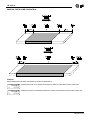
1
HB 548.44 User's manual b54 8 r E L H44 6 CONTROL OF HONING, MILLING AND GRINDING MACHINES WITH A MAXIMUM OF 20 HEADS, WITH THE POSSIBILITY TO CONTROL CASCADE STARTING OF THE HEAD MOTORS HB 548.44 LIST OF SUBJECTS DEALT WITH IN THIS MANUAL CHAP. 1 - INTRODUCTION - Supplementary nature of manual References Responsibility and validity Description of operation 1-1 1-2 1-3 1-4 CHAP. 2 - OPERATOR / MACHINE INTERFACE - Description of keyboard - Description of inputs - Description of outputs 2-1 2-2 2-3 CHAP. 3 - SETTING UP FOR OPERATION - Set-up Calibrations 3-1 3-2 CHAP. 4 - USE - Work programmes and auxiliary functions - Operation graphs and tables 4-1 4-2 CHAP. 5 - ASSISTANCE - Inputs and outputs troubleshooting - How to complete the technical assistance fax form - Warranty 5-1 5-2 5-3 Page 2 of 32 HB 548.44 CHAPTER 1 INTRODUCTION 1 - 1 SUPPLEMENTARY NATURE OF MANUAL This manual is to be considered as a supplement to the “Installation, maintenance and servicing manual”, which contains information on wiring, checking and eliminating faults, start-up and maintenance procedures. This manual gives instructions on the use and correct programming of the instrument. You are urged, therefore, to read the manual carefully and, if you have any queries, to contact QEM for further explanations by sending the assistance fax contained in the manual. 1 - 2 REFERENCES The documentation on the instruments designed and sold by QEM has been divided into different booklets for effective and speedy consultation, based on the specific type of information required. User manual Explanation of software. This is this manual, giving all the necessary information for the understanding and use of the instrument described. The manual deals with the instrument software, with information on the understanding, programming, calibration and use of the instrument described. After installing the instrument, following the instructions in the installation, maintenance and servicing manual, this user manual gives all the necessary instructions on the correct use and programming of the instrument. Hardware structure Basic information on the standard hardware in the series plus customisation possibilities. This booklet is appended to the user manual and describes the standard hardware configuration for the series of instruments described. It also gives the standard electrical, technical and mechanical specifications of the series, together with the hardware customisation possibilities in relation to the different software versions. Installation, maintenance and servicing manual All the necessary information for installation, maintenance and servicing. All the essential details on the correct maintenance and installation. The aim is to provide you with valid and accurate information for the manufacture of products of recognised quality and reliability. It also gives valid supporting information for servicing applications with QEM instruments installed. Page 3 of 32 HB 548.44 1 - 3 RESPONSIBILITY AND VALIDITY RESPONSIBILITY QEM declines all responsibility for any injury to persons or damage to objects resulting from the failure to observe the instructions and rules in this manual and the “Installation, maintenance and servicing manual”. It is furthermore specified that the customer/purchaser is bound to use the instrument according to the instructions provided by QEM and, if any doubts arise, to send a written query to QEM. Any authorisation for exceptions or substitutions in use, if contested, will be deemed valid by QEM only if in writing. The reproduction or handing over of all or part of this manual to third parties without the written authorisation of QEM is forbidden. Any transgression will result in a claim for compensation for the damages sustained. All rights deriving from patents or designs are reserved. QEM reserves the right to make partial or complete modifications to the characteristics of the instruments described or corresponding documentation. Objective The objective of this manual is to give the general rules for the use of the instrument described. Conservation of parameters Write down all the instrument setting and programming parameters and keep them in a safe place, to facilitate any future replacement or servicing operations. VALIDITY This manual is applicable to all instrumentation designed, manufactured and tested by QEM with the same order code. This document is valid in its entirety, barring errors or omissions. Instrument release Manual Release 6 8 0 1 Modifications to manual New Manual Add the note for the overrange counter in displays page Date of modifications 18 / 06 / 04 14 / 10 / 10 Page 4 of 32 HB 548.44 1 - 4 DESCRIPTION OF OPERATION The instrument HB 548.44 allows simultaneous management of up to a maximum of 20 working heads which can be arranged, using the set-up parameters, as honing machines, milling machines, grinding machines or as a command for cascade starting of the head motors. With input I6=OFF The instrument is used to execute honing and/or milling and/or grinding working of marble, wood, etc material. The system consists of a bi-directional encoder linked to the forward movement of the material on the conveyor belt and a maximum of 5 fixed sensors to detect piece presence and allow acquisition and correction of the image of the pieces introduced along the whole length of the conveyor belt. It is possibile to programme the outputs in 3 different configuration: 1) honing, 2) milling, 3) grinding When using the heads as honing machines, the correction data can be set with the advance or delay quota for head descent in respect to the slab start and the advance or delay quota of head ascent in respect to slab end. When using the heads as millers, the work data can be set with the advance or delay quota for milling start in respect to the slab start and the length of the milling or the advance or delay quota for milling end in respect to the slab end and the length of milling operations. When the heads are used as grinders, the programme can be set with the linear metre intervals at which head descent is to be set to compensate wear and the time for which it is to remain active. The work parameters can be memorised in programmes thus reducing machine setting times when production is changed. The instrument allows to perform, during the processing, some corrections by the working quotas in order to compensate eventual delay in machine’s response. These corrections are made bearing into consideration the shifting speed of the belt in order that automatically compensate the working quotas according to the speed variations of the same; we recommend then to perform the calibration by heads dynamic correction at the maximum speed of the belt in order that reduce error possibilitiy. The instrument allows the simultaneous processing of 30 pieces. During normal functions, the following parameters can be displayed: "Belt speed", "Metres worked", "Number of pieces processed", "Belt frequency meter" and "piece length". If in set-up the parameter "Automatic reset" is set on 0 or 2, the instrument memorises the quotas of pieces under process and these are reproposed when restarting. With input I6=ON The instrument is used to execute “the motors start in cascade” . In set-up will be set the delay time between the motor starting and the following Page 5 of 32 HB 548.44 1 - 5 STATEMENT OF PARAMETERS IN ORDER THAT THE INSTRUMENT OPERATES AS RELEASE 4 From release 4 to release 6 had introduced some modify/added by the instrument function. The changes are confern only the different set by the dynamic correction value (correction in function by the belt speed) of every single head enabled. Particulary until the release 4, such value had set to the inside by the function F+3 and for confirming at the instrument, the belt must be activated to the work speed (preferably the max speed) and than confirm the value with the enter key. Such procedure must be repeated for every single head enabled. From release 5 such procedure had modified/ changed. Now it is sufficient introduces at the new parameter of “reference ‘s speed” the value by the working speed (sole for all heads enabled) and always in the function F+3 introduces the correction values for every single head. They are also added the new functionalities as: - enables acquisition piece to zero speed - interspace - tolerance piece correction If not want to use these new functionalities, it is sufficient set to 0 at their parameters of set-up. Page 6 of 32 HB 548.44 CHAPTER 2 OPERATOR / MACHINE INTERFACE 2 - 1 DESCRIPTION OF KEYBOARD Key ÷ Function Normal operation: pressed after the “F” key, they select the functions available. Data input: allows entry of data. Normal operation: allows access to writing of work data. Data input: not used. Normal operation: Impulse pressure selects the previous display. Continuous pressure scrolls the displays at intervals of 0.25 seconds. Data input: inserts or removes the +/- sign. Normal operation: impulse pressure selects the successive display. Continuous pressure scrolls the displays at intervals of 0.25 seconds. Data input: inserts the decimal point. Normal operation: enables the selection of the functions. Data input: not used. Normal operation: pressed for 1 second (during displays) resets to zero the counters displayed. Data input: deletes the input value and reverts to the old value. Normal operation: not used. Data input: confirms the datum entered. Lights up when process data are introduced. This lights up when 30 (or more) pieces are being processed simultaneously. Lit when the encoder count is negative (in this case the encoder phases must be exchanged). Lights signaling not correction piece for sensors correction. Lights up when key "F" is pressed. Page 7 of 32 HB 548.44 + Access to password-protected functions. + Choice of the programme to be executed. + Restart working. + Head corrections. + Reset tollerance error piece correcton. + Input and output diagnostics. Page 8 of 32 HB 548.44 2 - 2 DESCRIPTION OF INPUTS Terminal bloach Name Operating logic Activation mode Polarizer Characteristics of inputs Refer to the chapter entitled “Electrical characteristics” in the “Hardware structure” booklet appended to this manual. Description 17 I1 ON C 16 Piece presence sensor 1. Fixed sensor allowing image to be acquired of the pieces introduced at the conveyor belt input. If input I1 = ON and the instrument switches off, the piece reading will be continued when the instrument and plant are switched on again. If the input I1 = OFF and the instrument switches off, the piece will be ignored when the instrument and plant are switched on again with input I1=ON. 18 I2 ON C 16 Piece presence sensor 2. Fixed sensor for correcting the position of the image of pieces introduced in an intermediate area of the conveyor belt. 19 I3 ON C 16 Piece presence sensor 3. Fixed sensor for acquiring the image position of pieces introduced in an intermediate area of the conveyor belt. 20 I4 ON I/C 16 Piece presence sensor 4. Fixed sensor for acquiring the image position of pieces introduced in an nS FI4 intermediate area of the conveyor belt. If not used as a piece sensor (in set-up "nS nS" less 4 and "FI4 FI4"set on 1), after activation for 2 seconds, operations are restarted. 21 I5 ON C 16 Piece presence sensor 5. Fixed sensor for acquiring the image position for the pieces introduced in an intermediate area of the conveyor belt. 22 I6 C 16 Head activation / Motors start. In heads activation the instrument activates and de-activates the outputs according to the comparison of the quotas for the pieces introduced. In motors start, the instrument activates outputs in cascade to start the heads motors. ON / OFF Terminal bloach Name Legend C = Continuous signal. I = Impulse signal. 1 Vac Instrument power supply voltage. Alternating voltage as per code in your order. 2 Vac Instrument power supply voltage. Alternating voltage as per code in your order. 3 GND Ground connection. A conductor of ∅ 4 mm is recommended. 4 + Transducers positive power supply. Positive voltage supplied by instrument for instrument and transducers inputs power. 5 - Transducers negative power supply. Negative voltage supplied by instrument for instrument and transducers inputs power. Descrizione Page 9 of 32 HB 548.44 Description Polarizer Operating logic Name Terminal bloach COUNT INPUTS 13 PHA N / P PE Input "phase A" incremental transducer. 14 PHB N / P PE Input "phase B" incremental transducer. PE Motors start. Enabled only when input I6 is active, it commands the start of the cascade sequence i starting the heads motors. 15 Z N/P For details of the count inputs, refer to the chapter entitled “Electrical characteristics” in the “Hardware structure” booklet appended to this manual. Legend N = Transducer with NPN logic. P = Transducer with PNP logic. 2 - 3 DESCRIPTION OUTPUTS Activation mode Polarizer ON C 6 Instrument reset. This output is activated according to the choice made with set-up parameter and is deactivated when the conveyor belt has made a complete turn so that there are no pieces undergoing the process. C 6 Heads activation / Motors start. This indicates the instrument's operation mode according to input I6 and tI t2 set-up parameters "tI tI" and "t2 t2". OFF = heads activation, ON = motors start. ON C 6 End of motors start. Signals the completion of the cascade motor start cycle. U4 ON / OFF P 6 Mix Out. Determines the functions of the mix cycle, with activation and deactivation times settable in set-up. U5 ON C 6 Piece alarm. Activated when the number of pieces in simultaneous operations is equal to or greater than 30. It is enable "Piece correction tollerance function, the U5 output is actives when it senses an highter correction to the tollerance value introduced. Name Description Terminal bloach Operating logic Characteristics of outputs Refer to the chapter entitled “Electrical characteristics” in the “Hardware structure” booklet appended to this manual. 7 U1 8 U2 9 U3 10 11 ON / OFF Legend C = Continuous signal. I = Impulse signal. Page 10 of 32 HB 548.44 Terminal bloach Name Operating logic Activation mode Polarizer Characteristics of output expansions U20 Refer to the chapter entitled “Electrical characteristics” in the “Hardware structure” booklet appended to this manual.. Description 24 U6 ON C 23 Descent of head 1. When activated, if the instrument is in function mode "Heads activation" (U2 = OFF), this commands descent of head 1; if instead the instrument is in function mode "Motors start" (U2 = ON) it commands the start of head motor 1. 25 U7 ON C 23 Descent of head 2. When activated, if the instrument is in function mode "Heads activation" (U2 = OFF), this commands descent of head 2; if instead the instrument is in function mode "Motors start" (U2 = ON) it commands the start of head motor2. 26 U8 ON C 23 Descent of head 3. When activated, if the instrument is in function mode "Heads activation" (U2 = OFF), this commands descent of head 3; if instead the instrument is in function mode "Motors start" (U2 = ON) it commands the start of head motor 3. 27 U9 ON C 23 Descent of head 4. When activated, if the instrument is in function mode "Heads activation" (U2 = OFF), this commands descent of head 4; if instead the instrument is in function mode "Motors start" (U2 = ON) it commands the start of head motor 4. 28 U10 ON C 23 Descent of head 5. When activated, if the instrument is in function mode "Heads activation" (U2 = OFF), this commands descent of head 5; if instead the instrument is in function mode "Motors start" (U2 = ON) it commands the start of head motor 5. 29 U11 ON C 23 Descent of head 6. When activated, if the instrument is in function mode "Heads activation" (U2 = OFF), this commands descent of head 6; if instead the instrument is in function mode "Motors start" (U2 = ON) it commands the start of head motor 6. 30 U12 ON C 23 Descent of head 7. When activated, if the instrument is in function mode "Heads activation" (U2 = OFF), this commands descent of head 7; if instead the instrument is in function mode "Motors start" (U2 = ON) it commands the start of head motor 7. 31 U13 ON C 23 Descent of head 8. When activated, if the instrument is in function mode "Heads activation" (U2 = OFF), this commands descent of head 8; if instead the instrument is in function mode "Motors start" (U2 = ON) it commands the start of head motor 8. 32 U14 ON C 23 Descent of head 9. When activated, if the instrument is in function mode "Heads activation" (U2 = OFF), this commands descent of head 9; if instead the instrument is in function mode "Motors start" (U2 = ON) it commands the start of head motor9. 33 U15 ON C 23 Descent of head 10. When activated, if the instrument is in function mode "Heads activation" (U2 = OFF), this commands descent of head 10; if instead the instrument is in function mode "Motors start" (U2 = ON) it commands the start of head motor 10. 35 U16 ON C 34 Descent of head 11. When activated, if the instrument is in function mode "Heads activation" (U2 = OFF), this commands descent of head 11; if instead the instrument is in function mode "Motors start" (U2 = ON) it commands the start of head motor 11. 36 U17 ON C 34 Descent of head 12. When activated, if the instrument is in function mode "Heads activation" (U2 = OFF), this commands descent of head 12; if instead the instrument is in function mode "Motors start" (U2 = ON) it commands the start of head motor 12. 37 U18 ON C 34 Descent of head 13. When activated, if the instrument is in function mode "Heads activation" (U2 = OFF), this commands descent of head 13; if instead the instrument is in function mode "Motors start" (U2 = ON) it commands the start of head motor 13. Continued on next page Page 11 of 32 Terminal bloach Name Operating logic Activation mode Polarizer HB 548.44 Description 38 U19 ON C 34 Descent of head 14. When activated, if the instrument is in function mode "Heads activation" (U2 = OFF), this commands the descent of head 14; if instead the instrument is in function mode "Motors start" (U2 = ON) it commands the start of head motor 14. 39 U20 ON C 34 Descent of head 15. When activated, if the instrument is in function mode "Heads activation" (U2 = OFF), this commands the descent of head 15; if instead the instrument is in function mode "Motors start" (U2 = ON) it commands the start of head motor 15. 40 U21 ON C 34 Descent of head 16. When activated, if the instrument is in function mode "Heads activation" (U2 = OFF), this commands the descent of head 16; if instead the instrument is in function mode "Motors start" (U2 = ON) it commands the start of head motor16. 41 U22 ON C 34 Descent of head 17. When activated, if the instrument is in function mode "Heads activation" (U2 = OFF), this commands the descent of head 17; if instead the instrument is in function mode "Motors start" (U2 = ON) it commands the start of head motor 17. 42 U23 ON C 34 Descent of head 18. When activated, if the instrument is in function mode "Heads activation" (U2 = OFF), this commands the descent of head 18; if instead the instrument is in function mode "Motors start" (U2 = ON) it commands the start of head motor 18. 43 U24 ON C 34 Descent of head 19. When activated, if the instrument is in function mode "Heads activation" (U2 = OFF), this commands the descent of head 19; if instead the instrument is in function mode "Motors start" (U2 = ON) it commands the start of head motor 19. 44 U25 ON C 34 Descent of head 20. When activated, if the instrument is in function mode "Heads activation" (U2 = OFF), this commands the descent of head 20; if instead the instrument is in function mode "Motors start" (U2 = ON) it commands the start of head motor 20. Key C = Continuous signal. Page 12 of 32 HB 548.44 CHAPTER 3 SETTING UP FOR OPERATION 3 - 1 SET-UP As these parameters set the operating mode of the instrument, access is restricted to the installer only. A password must be entered to access the programming, with the following procedure: Description Keyboard Access the set-up programming. + Display PASS H ... 0 = ON Introduce the access code "548" and confirm with ENTER. Exit is possible at any time after introducing the password by pressing the F key. FUNCTION DISPLAY DESCRIPTION FE 400000 Encoder resolution This parameter sets what the encoder revolution impulses must be multiplied by to have the length display in the desired unit of quota. Values from 0.00200 to 4.00000 can be entered, bearing in mind that the frequency of the PH phases must not exceed the instrument’s maximum count frequency. N.B. Refer to the “Installation, maintenance and servicing manual". Number of piece presence sensors nS 1 This parameter indicates how many piece presence sensors are used in acquiring the images of the pieces introduced (no long modification). This display appears when the parameter "Number of piece presence sensors" is greater than 1 Piece presence sensor interaxis (2÷5) Max. 19999 Number of heads Max. 20 Heads interaxis (1÷20) Max. 19999 S En Sor E 2 12345 nt i 12 n t Er AS I 12345 This is the distance between piece presence sensor 1 and piece presence sensors 2, 3, 4 and 5. The display will show only the interaxes relative to the sensors programmed with parameter nS "nS nS". Number of heads used on the equipment. By setting the value lower than or equal to 8, the interruption of comparisons is 1 millisecond. By setting a value of more than 8, the interruption of comparisons is 2 milliseconds. This is the distance from the heads to the piece presence sensor 1. The display will show only the interaxis relative to the number nt of heads programmed in parameter "nt nt". Page 13 of 32 HB 548.44 FUNCTION DISPLAY DESCRIPTION SCEL t A Choice of head functions (1÷20) I 0 0 = Head not present. 1 = Honing head. 2 = Milling head. 3 =Grinding head. Heads enabled at zero speed Zero speed threshold ( min.= 1) Filter speed threshold Average readings in stabilisation Number of piece presence input checks Ab 0 0 = When the machine is running below the zero speed threshold SO (parameter "SO SO"), the heads remain in position. 1 = When the machine is running below the zero speed threshold SO (parameter "SO SO"), all the heads are raised and descend again when the machine restarts and the speed exceeds the threshold. SO SF iS iI rA 1234 123 99 99 0 This is the number of encoder impulses (primary encoder impulses) read in the unit of time (1 second) below which the instrument considers the machine to be at a stop. This is the threshold of speed variations (expressed in m / min.) within which the display filter is inserted. Indicates every how many readings in stabilisation the displayed speed is to be calculated when the reading variations are inferior SF SF". to the threshold programmed in parameter "SF The instrument checks the inputs status every millisecond. This parameter indicates for how many checks, and therefore for how many milliseconds, the input must maintain the logical status so that the instrument can acquire the variation. 0 = The instrument memorises the quotas of the pieces being processed and retains them after being switched off. 1 = When the instrument is switched on again it activates output U1. Automatic reset 2 = When exiting programming of set-up parameters, or when work data are changed, the instrument activates output U1. 3 = When the instrument is restarted on exiting the set-up parameters, or when work data are changed, it activates output U1. Page 14 of 32 HB 548.44 FUNCTION DISPLAY Time necessary to activate start Time necessary to start activation Motor start interval time tI t2 tS Ut DESCRIPTION 123 This is the delay (expressed in seconds) when activating input I6 to change the instrument's function mode from "Activate heads" to "Start motors". 123 This is the delay (expressed in seconds) when deactivating input I6 to change the instrument's function mode from "Start motors" to "Activate heads". 123 Used with the instrument in function mode "Start motors", this indicates the time (expressed in seconds), of the delay between the start of one motor and the next. 0 tA td 0 =The times for activation "tA tA" and deactivation "td td" are expressed in seconds. tA 1 = The time for activation "tA tA" is expressed in seconds, the time td for deactivation "td td" is expressed in minutes. Unit of measure for mix times tA 2 =The time for activation "tA tA" is expressed in minutes, the time td for deactivation "td td" is expressed in seconds. td 3 = The times for activation "tA tA" and deactivation "td td" are tA expressed in minutes. Output activation time "Mix out" (U4) Max. 999.99 Output deactivation time "Mix out" (U4) Max. 999.99 tA td 123 123 This is the time (expressed in minutes or seconds) for activating output U4 (mix out) to execute the mix cycle. This is the time (expressed in minutes or seconds) for deactivating output U4 (mix out) to execute the mix cycle. This display appears if the parameter "Number of piece presence sensors" is less than 4 0 = The input is not used. Functions of input I4 Piece presence offset input (I1) Min. -999 Max. 999 FI 4 0 OFFSEt iI 990 1 = The input, activated for 2 seconds, restarts operations. The keyboard function "F + 2" is inhibited. This is the difference in intervention point between the ascent front and that of descent of input I1 (piece presence). Practically the value introduced anticipates (positive value) or delays (negative value) the end of the piece in respect to the descent front of input I1. Page 15 of 32 HB 548.44 FUNCTION DISPLAY DESCRIPTION C o n FMEM 0 0 = Programming of work data is one only for all heads (maximum number of programmes = 74). 1 =Programming of work data is separate for each single head (maximum number of programmes = 8). 2 = Programming of work data is divided in two groups (maximum number of programmes = 37). 3 = Programming of work data is divided in three groups (maximum number of programmes = 24). 4 = Programming of work data is divided in four groups (maximum number of programmes = 18). Memory configuration N.B. See appropriate paragraph. Reference UE L r i F It is the speed expressed in mt/min of the comparison of parameters “heads dynamic correction” (F+3) and “offset” (setup). Ab u EL 0 0 = Even when the belt is lower than the value inserted in the “zero threshold speed” it is acquired all the state change (activation/ de-activation) by the I1 input piece presence. 123 speed 0 Enabling piece acquisition to zero speed Interspace Min = 0 Max = 9999 1 =When the belt speed is lower than the value inserted in the “zero threshold speed” it is not acquired the de-activation by the I1 input piece presence. IP 100 This parameter establishes if it must consider one piece single, two pieces that are between them a lower space that programmed in this parameter N.B. But the piece-count counts always 2 separate pieces This display appears if the parameter "Number of piece presence sensors"is greater than 1 t Tolerance for sensor for piece correction o L LCo r 1234 Max.9999 It is the tolerance of the sensor for piece correction respect of the piece beginning. If the piece position is different for more than this value, the instrument intervenes into modality fixed (established) to the parameter “function mode piece tolerance correction”. This parameter must be set to a lower value to the min. measurement by the working pieces. N.B. If is set to 0, the control are disable. This display appears if the parameter "Tolerance for sensor for piece correction" are different to "0" Function method “sensor tolerance piece correction” M Ft o L LC 0 0= If it is sensed an tolerance error no correct the piece position 1= If it is sensed an tolerance error, the piece is not worked any more until his machine exit. N.b. When an tolerance error intervenes, they are actived in continuous method the L4 Led and the U5 output. Between F+4 function can be reset to zero the L4 led and U5 output. When programming of the last function is terminated, the display in use before entering set-up will reappear. Page 16 of 32 HB 548.44 MEMORY CONFIGURATION The groups are sub-divided according to the following formula: Number of heads used (set-up) Memory configuration (set-up) The eventual remainder is added to the last group. Example Number of heads = 17 Memory configuration =3 The first group consists of heads 1, 2, 3, 4 and 5 The second group consists of heads 6, 7, 8, 9 and 10 The third group consists of heads 11, 12, 13, 14, 15, 16 and 17 N.B. Both honing and milling heads can function simultaneously within the same group. 3 - 2 DYNAMIC CORRECTION HEADS For every head enabled, there is the possibility of inserting a correction value on the intervention quota to compensate any eventul differences in the same heads’ time intervention. Description Keyboard Access to head correction function + Display C or t ES I - 1234 = ON The operator can introduce the correction descent/ascent value required (max. 9999, min. -9999) and confirm with ENTER. On confirming with enter is enabled the introduction of descent/ ascent correction by the second head. ÷ N.B. If the head is not enabled or in “grinder” configuration, the display is referred to the next head. The correction values introduce are refering to the “reference speed” introduced in set-up. The operaton can introduce the correction descent/ascent head value 2 required and confirm with ENTER, so until to the correction by the last head enabled. ÷ C or t ES 2 - 1234 By pressing the shown key after making a change and before confirming with ENTER, the display will return to showing the value present before the change. Press the shown key the diplay the succession of correction value. To exit the function at any time, press the shown key. = OFF Page 17 of 32 HB 548.44 CHAPTER 4 USE 4 - 1 WORK PROGRAMMES AND AUXILIARY FUNCTIONS INTRODUCING THE WORK PROGRAMMES ( SET-UP PARAMETER "MEMORY CONFIGURATION SET ON 0) Description Keyboard Display Pr o Gr Access to writing of work programmes. nr 1 = ON The operator can choose the programme in which to enter work data and confirm with ENTER. ÷ N.B. If only honing heads have been programmed in set-up, only the data relative to honing heads will appear; if only milling heads have been programmed, only the data relative to milling heads will appear and if only grinding heads have been programmed, only the data relative to grinding heads will appear. With a honing head The operator can introduce the delay or advance (expressed in millimetres) between the start of the piece and the descent of the head (start of honing operations) and confirm with ENTER. A request is made to introduce the delay or advance (expressed in millimetres) between the end of the piece and the ascent of the head (end of honing operations). The operator can introduce this value and confirm with ENTER. The screen will return to the displays in use. With a milling head The operator can enter the distance (expressed in millimetres) between the start of the piece and the start of milling (start of milling operations) and confirm with ENTER. A request is made to introduce the distance (expressed in millimetres) between the end of the piece and the end of milling (end of milling operations). The operator can enter its value and confirm with ENTER. IF N.B. If the programmed parameter "IF IF" is other than zero, the FF parameter "FF FF" must be set on zero and vice versa. A request is made to introduce the length (expressed in millimetres) of milling (length of milling operations). The operator can enter its value and confirm with ENTER. The screen will return to the displays in use. ÷ ÷ IL FL IF FF LF Qu o t A 12345 Qu o t A 2345 Qu o t A 12345 Qu o t A 2345 Qu o t A 1000 Continued on next page Page 18 of 32 HB 548.44 Description With a grinding head The operator can introduce the linear metres, after which the solenoid valve must be operated to compensate the wear on the grinder, and confirm with ENTER. If the operator sets the value zero the head will be deactivated. A request is made to introduce the time (expressed in seconds) of head activation after reaching the metres set in the previous parameter. The operator can introduce its value and confirm with ENTER. The screen will return to the displays in use. Keyboard Display IM tM Mo L A 12345 t i nEr 5000 rA N.B. If in set-up the parameter "rA rA" is set on 2 or 3, and a variation is made to the data in use, output U1 is activated (any eventual pieces being processed are reset to zero). Each time the programme is changed, or each time the value is changed for the metres set in the heads configurated as grinders, the instrument will activate the relative outputs for the time that has been set. Press the keys shown to scroll the various displays. To exit at any time, press the key shown. = OFF Page 19 of 32 HB 548.44 INTRODUCING THE WORK PROGRAMMES ( SET-UP PARAMETER "MEMORY CONFIGURATION SET ON 1) Description Keyboard Display Access to writing of work programmes. Pr o Gr nr 1 = ON The operator can choose the programme in which to enter work data and confirm with ENTER. ÷ With a honing head The operator can introduce the delay or advance (expressed in millimetres) between the start of the piece and the descent of head 1 (start of honing operations) and confirm with ENTER. ÷ Qt A I IL 12345 I FL 2345 ÷ 2 IL 12345 ÷ I IF 12345 1 FF 2345 I LF 1000 A request is made to introduce the delay or advance (expressed in millimetres) between the end of the piece and the ascent of head 1 (end of honing operations). The operator can introduce this value and confirm with ENTER. If the operator sets the value zero Qt A the head will be disabled. A request is made to introduce the delay or advance (expressed in millimetres) between the start of the piece and the descent of head 2 (start of honing operations). The operator can introduce the value and confirm with ENTER. On confirming with ENTER a request is made to introduce the delay, or the advance, between the end of the piece and the ascent of head 2 and so forth up to the programming of the last enabled head. With a milling head The operator can enter the distance (expressed in millimetres) between the start of the piece and the start of milling with head 1 (start of milling operations) and confirm with ENTER. A request is made to introduce the distance (expressed in millimetres) between the end of the piece and the end of milling with head 1 (end of milling operations). The operator can introduce its value and confirm with ENTER. IF N.B. If the programmed parameter "IF IF" is other than zero, the FF parameter "FF FF" must be set on zero and vice versa. Qt A Qt A Qt A With both quotas at zero the head is disabled. A request is made to introduce the length (expressed in millimetres) of the milling performed by head 1 (length of milling operations). The operator can introduce its value and confirm with ENTER. On confirming with ENTER a request is made to introduce the distance between the start of the piece and the start of milling operations with head 2 and so forth up to the programming of the last enabled head. Qt A Continued on next page Page 20 of 32 HB 548.44 Description With a grinding head The operator can introduce the linear metres, after which the solenoid valve must be operated to compensate the wear on the grinder, and confirm with ENTER. If the operator sets the value Keyboard Display I IM Mo L A 12345 zero the had will be disabled. A request is made to introduce the time (expressed in seconds) of head activation after reaching the metres set in the previous parameter. The operator can introduce its value and confirm with ENTER. The screen will return to the displays in use. I tM tnr 5000 rA N.B. If in set-up the parameter "rA rA" is set on 2 or 3, and a variation is made to the data of the programme in use, output U1 is activated (any eventual pieces being processed are reset to zero). Each time the programme is changed, or each time the value is changed for the metres set in the heads configurated as grinders, the instrument will activate the relative outputs for the time that has been set. Press the keys shown to scroll the various displays. To exit at any time, press the key shown. = OFF Page 21 of 32 HB 548.44 INTRODUCING THE WORK PROGRAMMES (SET-UP PARAMETER "MEMORY CONFIGURATION SET ON 2, 3, 4) Description Keyboard Display Pr o Gr Access to writing of work programmes. nr 1 = ON The operator can choose the programme in which to enter work data and confirm with ENTER. With a honing head The operator can introduce the delay or advance (expressed in millimetres) between the start of the piece and the descent (start of honing operations) of the heads relative to the first group (A) and confirm with ENTER. ÷ A IL Qu o t A A FL Qu o t A A IF Qu o t A A FF Qu o t A A request is made to introduce the length (expressed in millimetres) of milling (length of milling operations) performed with the heads relative to the first group (A). The operator can introduce its value and confirm with ENTER. On confirming with ENTER a request is made for the programming of the heads relative to successive groups (B if in set-up the parameter "Memory configuration" is set on 2, B and C if set on 3 and B, C and D if set on 4). A LF Qu o t A With a grinding head The operator can introduce the linear metres, after which the solenoid valve must be activated to compensate the wear on the grinder, and confirm with ENTER. If the operator sets the value A IM Mo L A A request is made to introduce the delay or advance (expressed in millimetres) between the end of the piece and the ascent (end of honing operations) of the heads relative to the first group (A). The operator can introduce its value and confirm with ENTER. On confirming with ENTER a request is made to program the heads relative to the successive groups (B if in set-up the parameter "Memory configuration" is set on 2, B and C if set on 3 and B, C and D if set on 4). If the operator sets the value zero the group ÷ ÷ 12345 2345 is disabled. With a milling head The operator can introduce the distance (expressed in millimetres) between the start of the piece and the start of milling (start of milling operations) by the heads relative to the first group (A) and confirm with ENTER. A request is made to introduce the distance (expressed in millimetres) between the end of the piece and the end of milling (end of milling operations) by the heads relative to the first group (A). The operator can introduce its value and confirm with ENTER. IF N.B. If the programmed parameter "IF IF" is other than zero, the FF parameter "FF FF" must be set on zero and vice versa. 12345 2345 With both quotas on zero the group is disabled. 1000 12345 zero the group will be disabled. Continued on next page Page 22 of 32 HB 548.44 Description Keyboard A request is made to introduce the time (expressed in seconds) for activating the grinding heads belonging to group A when reaching the metres set in the previous parameter. The operator can introduce its value and confirm with ENTER. The screen will return to the displays in use. rA N.B. If in set-up the parameter "rA rA" is set on 2 or 3, and a variation is made to the data of the programme in use, output U1 is activated (any eventual pieces being processed are reset to zero). Each time the programme is changed, or each time the value is changed for the metres set in the heads configurated as grinders, the instrument will activate the relative outputs for the time that has been set. Display A tM tnr 5000 Press the keys shown to scroll the various displays. = OFF To exit at any time, press the key shown. CHOOSING THE WORK PROGRAMME TO BE EXECUTED Description Keyboard Access to programme choice functions. Display SCEL t A + Pr G 1 = ON The operator can introduce the number of the programme to be executed and confirm with ENTER. The programme selected will be executed and the screen will return to the displays in use. ÷ N.B.If selection is made of a programme different from that in use and the parameter for automatic set-up reset "rA" is set on 2 or 3, on confirming with ENTER, output U1 will be activated (and any eventual pieces being processed will be reset to zero). To exit the function at any time, press the key shown. = OFF WORKING RESTART Description Access the operations restart function if in set-up the parameter FI4 "FI4 FI4" is not set on 1. Keyboard + Display r ESt Ar t L AU = ON By pressing the ENTER key for 2 seconds, the instrument will perform operations restart and the screen will return to the display in use. × 2 sec. = OFF To exit the function at any time, press the key shown. Page 23 of 32 HB 548.44 RESET TOLERANCE ERRORS OF PIECE CORRECTION Description Enter the function for zero reset tolerance errors of piece correction if in set-up the paramenter EoLLCor is different to 0. Keyboard + Display r ESEt t o L Lc o r = ON Pressing key ENTER for 2 seconds, the instrument executes an reset by the tolerance error of piece correction (L4 led and U5 output are de-activated) × 2 sec. = OFF To exit the function at any time, press the shown key. DISPLAYS Description Keyboard Upper right hand display Programme in use. Lower right hand display Linear metres worked. By pressing the shown key, the counter for worked linear metres is reset to zero. Display P r G 104 ML 15 00 × 1 sec. N.B.: If a series of horizontal dashes, it means that the counter is in overrange, so is necessary to reset it in order to allow the right grinding heads' functioning. un nP Upper right hand display Belt speed expressed in m / min. Lower right hand display Number of pieces worked. By pressing the shown key, the worked piece counter is reset to zero. Should the operator introduce a value that is not within acceptable limits: 5 00 × 1 sec. F C Upper right hand display Frequency meter. Lower right hand display Piece length (determined by the set-up parameter "Piece presence offset"). Press the key shown to reset count to zero. 123 123 123456 × 1 sec. Err or Page 24 of 32 HB 548.44 4 - 2 OPERATION GRAPHS AND TABLES HONING AND MILLING HEADS N.B. Only the piece presence sensor 1 allows by the piece lenght acquisition. The sensors remainders execute only the correction. Particularly they move the working head point activation in function by the count acquired when the sensor is actived, without change the lenght. Page 25 of 32 HB 548.44 IMPIEGO TESTE COME LEVIGATRICI Example: Before setting the work data, the operator must set two parameters: IL FL Qu o t A Inserting the quota "a" to identify the advance or delay in head descent from piece start. Qu o t A Inserting the quota "b" to identify the advance or delay in head ascent in respect to the piece end. 12345 12345 Page 26 of 32 HB 548.44 USE OF HEADS AS A MILLING MACHINE Use of the head as a miller can be made in two ways. 1) Milling on piece start. 2) Milling on piece end. Case nº 1. Example. If head 2 is configurated as a milling machine and milling is to be performed on the piece start, the operator will set the programme in which to set the following parameters. IF FF LF Qu o t A The operator must insert quota "a" to identify the delay in descent of the head from piece start. Qu o t A This parameter is forced to zero and is used only in case nº 2. Qu o t A The operator must insert quota "b" to identify the length of the milling to be performed. 1234 0 1000 Page 27 of 32 HB 548.44 Case nº 2. Example. If head 3 is configurated as a milling machine and milling is to be made at the end of the piece, the operator must set the following parameters in the work programme: IF FF LF Qu o t A This parameter must be set on zero to enable the successive one. If zero is not set, return is made to case 1. Qu o t A The operator must insert quota "c" to identify the distance between the end of the piece and the end of the milling operation. Qu o t A The operator must insert quota "d" to identify the length of the milling to be performed. 0 2345 1000 Case nº 2 has been created to simplify things but can be considered equal to case nº 1, with the only difference that quota "a" of case nº 1, in case nº 2 should be calculated as: a = (Piece length - c - d) Page 28 of 32 HB 548.44 USE AS MOTORS START I6 Z U2 U3 U6 U7 U8 U25 tI tS tS t2 I6 = Heads activation (OFF) / Motors start (ON). Z = Motors start. U2 = Heads activation (OFF) / Motors start (ON). U6÷U25 = Heads command 1÷20. U3 = End of start. Si attiva l'ingresso I6 e quindi lo strumento cambia il modo di funzionamento da attivazione teste ad avviamento motori. Tutte le uscite relative alle teste (U6÷U25) vengono disattivate. tI Dopo il tempo "tI tI" (tempo passaggio attivazione-avviamento) lo strumento attiva l'uscita U2 e abilita il modo di funzionamento avviamento motori. All'attivazione dell'ingresso "Z" si ha l'inizio della procedura di partenza in cascata dei motori e si attiva l'uscita relativa alla prima testa abilitata in set-up in ordine crescente. tS Trascorso il tempo "tS tS" (tempo intervallo start motori) si ha l'attivazione dell'uscita relativa alla successiva testa abilitata in set-up. tS Trascorso il tempo "tS tS" (tempo intervallo start motori) si ha l'attivazione dell'uscita relativa alla successiva testa abilitata in set-up. Nel caso in cui venga attivato nuovamente un comando di start motori (Z) questo non viene elaborato. Un nuovo comando di start sarà elaborato solo nel caso in cui lo strumento passi prima in modo di funzionamento attivazione teste (U2 = OFF) e poi ritorni in modo di funzionamento avviamento motori (U2 = ON). Si attiva l'uscita dell'ultima testa abilitata e ha termine la procedura di start motori, segnalata dall'attivazione dell'uscita U3. Si disattiva l'ingresso I6 e lo strumento cambia il modo di funzionamento da avviamento motori ad attivazione teste. Tutte le uscite relative alle teste (U6÷U25) e l'uscita U3 vengono disattivate. t2 Trascorso il tempo "t2 t2" (tempo passaggio avviamento-attivazione) lo strumento disattiva l'uscita U2 ed abilita il modo di funzionamento attivazione teste. Page 29 of 32 HB 548.44 MIX CYCLE U4 tA td tA td tA td tA td tA The mix cycle starts when the instrument is switched on and will continue to activate and deactivate output "U4" tA td (mix out), according to the times set in set-up parameters "tA tA" and "td td" until the instrument is switched off. Page 30 of 32 HB 548.44 CHAPTER 5 ASSISTANCE 5 - 1 INPUT AND OUTPUT TROUBLESHOOTING The instrument provides troubleshooting for the input and digital output logic status; according to the numbers displayed, it is possible to understand whether an input arrives at the instrument and if an output has been energised. The first display after access to the diagnostics function refers to the inputs status; if number 1 is displayed, this means that input 1 has been activated; if number 2 is shown, this means that input 2 has been activated and so on. Input Z (transducer zero impulse) is signalled with a C; if this is shown, there is no zero impulse; if not shown, the zero impulse is supplied to the instrument. The following display refers to the logic status of the digital outputs. The same correspondence (each number corresponds with its equal output); for example, the presence of the number 4 indicates that the instrument is energising output 4. Description Access the troubleshooting function. The input (I) status will be displayed. Keyboard + Display i c 12345 6 = ON Press the ENTER key to pass to display the outputs status (o). o 12345 67 89Ab c d Press the ENTER key to display the expansion outputs status (u). u EFGHi L M n PQr S To exit the function, press "F". = OFF 5 - 2 HOW TO COMPLETE THE TECHNICAL ASSISTANCE FAX FORM If we are to provide you with a speedy, efficient and high-quality service, we need your help. If ever you need the assistance of QEM in dealing with any technical problems that may arise in your applications and, even though all the instructions in the “Installation, maintenance and servicing” manual have been followed, the problem persists, we invite you to fully complete the fax form enclosed with the installation, maintenance and servicing manual and send it to the QEM assistance office. In this way, our service engineers will have all the essential information for the understanding of your problem (thus avoiding long and costly telephone calls). In thanking you for co-operation, we wish you all the best in your work. NOTE If ever you have to send an instrument to us for repair, please read the points below carefully. - If possible, use the original packaging. In any event, the packaging must protect the instrument from knocks during its journey. - Enclose a detailed description of the problem that has occurred, along with the part of the wiring diagram where the instrument is located, in the package. If the problem involves data storage, enclose the instrument set-up programming (set-up, work quotas, auxiliary parameters ...). - If necessary, ask us specifically for an estimate on the repairs. If no estimate is requested, the cost will be calculated on completion. - Our service engineers will give priority to instruments that are sent to in accordance with the instructions in these notes. Page 31 of 32 HB 548.44 5 - 3 WARRANTY The warranty conditions are as stated in the general conditions of sale. NOTE This product is an electronic instrument and is thus not to be considered as a machine. Consequently, it is not subject to the requirements stated in EEC Directive 89/392 (Machines Directive). It is hereby specified that, if the QEM instrument is used as a component part of a machine, it must not be switched on if the machine does not comply with the Machines Directive. The instrument mark does not absolve the Customer fromthe fulfilment of his or her legal obligations regarding the finished product. Page 32 of 32