1
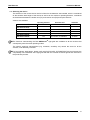
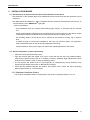
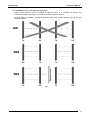
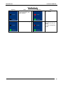
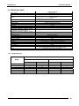
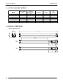
DS2 Instruction Manual ORIGINAL INSTRUCTIONS (ref. 2006/42/EC) Datalogic Automation S.r.l. Via Lavino, 265 40050 - Monte S. Pietro Bologna - Italy DS2 Ethernet Instruction Manual Ed.: 10/2012 © 2012 Datalogic Automation S.r.l. ALL RIGHTS RESERVED. Protected to the fullest extent under U.S. and international laws. Copying, or altering of this document is prohibited without express written consent from Datalogic Automation S.r.l. Datalogic and the Datalogic logo are registered trademarks of Datalogic S.p.A. in many countries, including the U.S.A. and the E.U. All brand and product names mentioned herein are for identification purposes only and may be trademarks or registered trademarks of their respective owners. Datalogic shall not be liable for technical or editorial errors or omissions contained herein, nor for incidental or consequential damages resulting from the use of this material. 22/10/12 INDEX 1. GENERAL INFORMATION ..................................................................................................................... 1 1.1. General description of the AREAscanTM light grid............................................................................ 1 1.2. Selecting the device ......................................................................................................................... 2 1.3. Typical applications .......................................................................................................................... 3 2 INSTALLATION MODES ........................................................................................................................ 4 2.1. Precautions to be observed for the choice and installation of the device ........................................ 4 2.2. General information on device positioning ....................................................................................... 4 2.2.1. Minimum installation distance ................................................................................................ 4 2.2.2. Minimum distance from reflecting surfaces ........................................................................... 5 2.2.3. Installation of several adjacent light grids .............................................................................. 6 3. MECHANICAL MOUNTING .................................................................................................................... 7 4. ELECTRICal connections...................................................................................................................... 8 4.1. Notes on connections....................................................................................................................... 9 5. FUNCTIONING MODES........................................................................................................................ 10 5.1. Detection mode .............................................................................................................................. 10 5.2. Measurement mode ....................................................................................................................... 10 5.3. Transition detection (number of transitions)................................................................................... 11 5.4. Notes on functioning mode ............................................................................................................ 11 5.5. Ethernet connection functioning..................................................................................................... 11 6. FUNCTION AND PROGRAMMING SELECTION................................................................................. 12 6.1. Remote programming..................................................................................................................... 12 6.1.1. DS2 user interface – General information ........................................................................... 13 6.1.2. Program installation ............................................................................................................. 13 6.1.3. Graphic user interface.......................................................................................................... 14 6.1.4. Connection with AREAscanTM DS2 series with Ethernet interface...................................... 14 6.1.5. Configuration of the AREAscanTM DS2 series with Ethernet interface ................................ 16 6.1.6. Functions.............................................................................................................................. 20 6.1.7. Teach-in ............................................................................................................................... 23 6.1.8. File saving of the configuration options ............................................................................... 26 6.1.9File loading of the configuration options ................................................................................ 27 7. AREAscanTM DS2 series – communication Protocol ....................................................................... 28 7.1. Packet description .......................................................................................................................... 28 7.1.1 Binary data packet structure ................................................................................................ 28 7.1.2. Short protocol binary data packet structure ......................................................................... 28 7.1.3. ASCII data packet structure ................................................................................................. 28 7.2 Operating mode: DS2 (server) Host Interface (client) ............................................................... 29 7.2.1. Packet description................................................................................................................ 29 7.3. Configuration mode: DS2 (server) Host (client)......................................................................... 32 7.3.1 Host appropriation procedure of the bus ............................................................................. 32 7.3.2 Command packet description: ............................................................................................. 32 8. DIAGNOSTIC FUNCTIONS AND LED INTERFACE ERROR SIGNALLING ...................................... 39 8.1. Device status visualization ............................................................................................................. 39 9. CHECKS AND PERIODICAL MAINTENANCE .................................................................................... 41 10.TECHNICAL DATA ............................................................................................................................... 42 10.1. Response time ......................................................................................................................... 42 11.lIST OF AVAILABLE MODELS ............................................................................................................ 43 12.OVERALL DIMENSIONS ...................................................................................................................... 43 Instruction Manual DS2 Ethernet 1. GENERAL INFORMATION 1.1. General description of the AREAscanTM light grid The AREAscanTM light grids are multibeam optoelectronic devices that can be used to detect objects, including small and transparent targets as well as for measurement detection. The variety of functions implemented make the DS2 a particularly flexible device that suits many different applications. The AREAscanTM light grids of the DS2 series are manufactured in accordance with the international Standards in force and in particular: CEI EN 60947-5-2: low voltage proximity devices CEI EN 50319: proximity switches: requirements for proximity switches with analogue output The device, consisting of emitter and receiver units housed inside sturdy aluminium profiles, generates infrared beams that detect any object positioned in the light grid’s detection field. The command and control functions are inside the two units; the connections are made through M12 connectors located in the lower side of the profiles. The synchronisation between the emitter and the receiver takes place via cable through direct connection between the two units. The control and management of the emitted and received beams are guaranteed by microprocessors. The operator obtains information relative to the light grid status and error conditions through LEDs located on the device and/or through the control interface of a remote PC. Some parts or paragraphs of this manual, containing important information for the operator, are proceeded by a note: Notes and detailed descriptions about particular characteristics of the AREAscanTM devices have been added to better explain functioning. DATALOGIC AUTOMATION Technical Support is available for questions related to the functioning and installation of the DS2 series light grids and for any information and/or suggestions necessary for a correct installation (see section 9 “Checks and periodical maintenance”). AREAscanTM ARE NOT safety devices; the use of the device for safety purposes and operator safeguarding is not conform and dangerous. 1 DS2 Ethernet Instruction Manual 1.2. Selecting the device The selection of the correct device version is linked to the detection area needed, which is considered as the sensitive area height of the device as well as to the maximum operating distance, considered as the distance between the emitter unit (TX) and receiver unit (RX) and optics interaxis. Versions are available: Operating distance Detection field interaxis DS2-05-07-060-JE 5m 84 beams; h=600mm 6.75mm DS2-05-07-075-JE 5m 105 beams; h=750mm 6.75mm DS2-05-07-090-JE 5m 126 beams; h=900mm 6.75mm DS2-05-07-120-JE 5m 168 beams; h=1200mm 6.75mm DS2-05-07-150-JE 5m 210 beams; h=1500mm 6.75mm DS2-05-07-165-JE 5m 231 beams; h=1650mm 6.75mm The functions characterising the DS2 AREAscanTM light grids are available on all the versions that consequently have the same operating modes. The specific technical characteristics (e.g. resolution, sensitivity etc) remain the same for all the versions, until differently indicated. For food industry applications, please verify with DATALOGIC AUTOMATION Technical Support the compatibility of the materials of the light grid shell with the eventual chemical agents that are used in the production process. 2 Instruction Manual DS2 Ethernet 1.3. Typical applications The following images supply an overview on some main applications. Object detection and measurement on conveyor belt 3 Control of the correct material positioning (opaque and transparent) during functioning (plastic, metal, paper etc) Loop control and positioning (also transparent material) Detection of objects with different shapes in the food industry Detection of objects in different positions (parallel beams) Detection of slots and holes in different positions DS2 Ethernet 2 Instruction Manual INSTALLATION MODES 2.1. Precautions to be observed for the choice and installation of the device The dimension of the smallest object to be detected should not to be lower than the resolution level of the device. The DS2 should be installed in a place compatible with the technical characteristics (see section 10 “Technical Data”) of the AREAscanTM light grids. Other considerations: - avoid installation near very intense and/or flashing light sources, in particular near the receiver unit. - strong electromagnetic interference can compromise the correct functioning of the device. Please contact DATALOGIC AUTOMATION Technical Service when this problem occurs. - the operating distance of the device can be reduced in the presence of smog, fog or airborne dust. - a sudden change in environment temperature, with very low minimum peaks, can generate a small condensation layer on the lenses and jeopardise functioning. - relevant variations of the power supply can reduce the operating distance of the device. 2.2. General information on device positioning Place the device near the detection area. Align the receiver (RX) and emitter (TX) units in order that they are the most parallel possible. Verify that the green receiver LED is on (stability condition), otherwise slight adjustments of both units have to be made in order to reach the stability position. Fix the receiver and emitter units on rigid supports not conditioned by strong vibrations using specific fixing brackets (see section 3 “Mechanical mounting”) Check that the distance between the receiver and emitter units is within the device operating distance (see section 10 “Technical data”) 2.2.1. Minimum installation distance The minimum installation distance corresponds to the minimum operating distance = 0.3 m. 4 Instruction Manual DS2 Ethernet 2.2.2. Minimum distance from reflecting surfaces Reflecting surfaces placed near light beams of the AREAscanTM device (over, under or laterally) may cause passive reflections that can compromise the detection of an object inside the controlled area (see Fig.1). Fig. 1 However, the object may not be detected if the receiver detects a secondary beam (reflected by the side-reflecting surface), even if the entering object interrupts the main beam. It is thus important to position the units at the correct distance from any reflecting surface: The minimum distance depends on: - device operating distance - reflecting surface nature - position of the object inside the sensitive area It is necessary to evaluate this distance on the field according to the operating conditions; however a minimum distance from the reflecting surface of about 0.5 m is suggested. 5 DS2 Ethernet Instruction Manual 2.2.3. Installation of several adjacent light grids When several devices must be installed in adjacent areas, it is necessary to prevent the interference between the emitter of one device and the receiver of another. Fig.2 provides an installation example of possible interference between different devices and two possible solutions. NO YES YES Fig. 2 6 Instruction Manual DS2 Ethernet 3. MECHANICAL MOUNTING The emitter and receiver units have to be mounted with the relevant sensitive surfaces facing each other. The connectors must be positioned on the same side and with the operating distance of the model used (see section 10 “Technical data”). The two units must be aligned and parallel as much as possible. To mount the device, insert the threaded pins supplied (see Fig.3) in the slots present on the two units. Depending on the particular application and/or type of support, the operator can use the fixing pins or the rigid fixing brackets supplied to mount the two units (see Fig.4). Fig. 3 Fig. 4 Rigid fixing brackets can be used where no big mechanical corrections are required during the alignment operation. Rotating supports for the correction of the unit inclination of ±1° on the medial transversal axis and of ±5° on the longitudinal axis, are available on request. In applications with particularly strong vibrations, the use of anti-vibration shock absorbers able to reduce the impact of vibrations together with threaded pins, rigid brackets and/or rotating supports are recommended. 7 DS2 Ethernet Instruction Manual 4. ELECTRICAL CONNECTIONS The electrical connection between the emitting and receiving units is made through a male M12 connector located in the lower part of the light grid. RICEIVER (RX) TX2 OUTPUT HOLD / OUTPUT ENABLE AUX 1 GND 6 5 3 7 1 AUX 2 SWITCHING OUTPUT 4 2 8 SYNC 1 2 3 4 5 6 7 8 = = = = = = = = white brown green yellow grey pink blue red = = = = = = = = RX- ANALOGUE OUTPUT 3 + VDC 1 RX+ 4 TX+ AUX 2 +VDC ANALOGUE OUT SWITCHING OUTPUT OUT HOLD / OUT ENABLE AUX 1 GND SYNC 1 2 3 4 = = = = brown white blue black = = = = RX + TX RX TX + EMITTER (TX) NOT USED GND 1 2 3 4 = = = = brown white blue black = = = = +VDC 2 1 3 4 SYNC +VDC NOT USED GND SYNC 8 Instruction Manual DS2 Ethernet 4.1. Notes on connections The following precautions regarding electrical connections have to be respected for the correct functioning of the AREAscanTM light grid. Shielded cables are not foreseen in the standard connection. However, if necessary, these cables can be used in presence of ground connection of both the unit and cable, as shown in Fig.5. External power supply Ground connection Fig. 5 In any case, these cables must not be placed in contact with or near any high voltage cables (e.g. motor power supplies, inverters, etc) that, generating strong electromagnetic fields, can compromise the correct functioning of the device. Ground connection of the two units is not necessary. However, if required, the connection is possible tightening the specific screw supplied instead of one of the 8 screws that lock the heads of each unit (see Fig.6). Follow the connection illustrated in Fig.5 when ground connection of the entire system is used. Fig. 6 9 DS2 Ethernet Instruction Manual 5. FUNCTIONING MODES The DS2 light grids detect and measure objects placed inside the detection area. Hence, beam interruptions can cause the switching of the digital output and the variation of the analogue output signal. Small objects (up to 12 mm) detection and geometrical measurements determined with approximately 6 mm resolution can be obtained by setting the device according to the different functioning modes. Beam scanning is sequential and the update of all the outputs is made at each scanning, within a period equal to the device response time. 5.1. Detection mode The detection mode is activated whenever at least one beam is interrupted inside the detection area. The activation causes the digital output switching (signalled by the powering of the yellow LED). The DS2 presents many different functions, listed below, that condition the switching output: Switching Output Mode: indicates if electrical current passes through switching output; the output can be normally closed (N.C.) or normally open (N.O.). Switching Output Delay: delays the re-setting of the switching output after detection. The delay time can be selected. Acquisition and detection (Teach-in): allows a conditioned detection of the object inside the detection area: if the object corresponds (without resolution) to the object detected during the Teachin phase, the output switches. On the contrary nothing happens. The following modes can be set: - absolute Teach-in detection: the output switches only if the previously set object is re-detected in the same position. - relative Teach-in detection: the output switches only if the previously set object (without resolution) is re-detected, independently from the position in the sensing area. 5.2. Measurement mode The measurement mode depends on the number of interrupted beams and causes the switching of the analogue output (and also of the digital output). The DS2 presents many different measurement functions, listed here below: Absolute measurements: measurement is obtained considering the first photoelement (1) as the reference beam beginning from the connector side. The DS2 light grid has in particular the following functions: 1. top beam: provides the measurement between the reference beam and the obscured beam furthest away from the reference 2. bottom beam: provides the measurement from the reference beam and the obscured beam closest to the reference 3. middle beam: provides the measurement of the beam corresponding to the medium point between the obscured beam furthest away from the reference and the obscured beam closest to the reference Relative measurements: measurement is obtained not considering absolute references. The measurement depends on the number of obscured beams. The DS2 light grid has in particular the following functions: 4. total beams: supplies the measurement corresponding to the total number of obscured beams 5. total contiguous beams: supplies the measurement corresponding to the maximum number of contiguous beams obscured 10 Instruction Manual DS2 Ethernet 5.3. Transition detection (number of transitions) The transition detection counts the number of transitions in the detection area. The number of transition increases each time that an object is detected inside the detection area and decreases each time the objects remain outside (transition light->dark). 5.4. Notes on functioning mode The DS2 light grids can configure the beam reference status, specifically selecting it from the user interface. The default selection is “dark beam”, but the operator can select the complementary situation i.e. “light beam”. Not all the functions can be selected using dip-switches. Please refer to the following tables to discover the local programmability of the device. The analogue voltage value is supplied, in these cases, without direct correspondence, as indicated in the tables found in page 12, 24 and 26. The formula to determine the voltage is obtained with the following syntax: VOUT =VRES* NBEAM [xxx ; yyy] Where VOUT = voltage value of the analogue output VRES = 10V/total n° of beams of the device = Voltage value corresponding to the minimum resolution (obtained obscuring only one beam) NBEAM [xxx ; yyy] = Number of beams belonging to the group [XY] (i.e. between “xxx” beam and “yyy” beam) Please note that the longer DS2 is, the less conditioning is VRES. In the worst case VRES = 43 mV ! (using the DS2 165 model) 5.5. Ethernet connection functioning Output data updating is usually made at the end of each scanning cycle. This conditions enormously the response time of the DS2 light grid, as it is depends data structure and information detail that has to be transmitted. Some serial configuration commands have been added to make the device flexible to different applications. The remote user interface completely controls these commands. Transmission standard selection: Function allows the operator to choose data structure; it is possible to choose ASCII or Binary data. Partial transmission is preferred for applications where time factors are important. Further partial transmission is short protocol which transmission is purely binary and extremely fast. Function is enable for single measure only. For data transmission details please see “Communication protocol” section of the user manual. Data sending mode selection: function allows the operator to choose when to send the data. The sending can also be inhibited by a specific selection (via “software”, using the specific command, via “hardware” programming the output enable input – pin 5 RX connector – using the user interface). The sending mode selection can be reached only via remote control. Four options can be selected: data sending at each machine cycle which is the default setting, data sending at each output status change, data sending at analogue output value change, user sending request, using the interface command button. This last condition can be requested also by an external command previously programming the device (per details please see section 7 “Communication protocol”). 11 DS2 Ethernet Instruction Manual 6. FUNCTION AND PROGRAMMING SELECTION The functions implemented in the AREAscanTM DS2 light grids can be selected via remote. The default configurations are given below: Default configuration for emitter unit The device is supplied with the maximum emission adjustment setting (minimum sensitivity) Sensitivity adjustment Sensitivity adjustment is made using the trimmer located inside the emitter unit lid. This function allows the operator to change the emitter intensity. With regard to the programmation and the selectable functions, refer to following paragraphs. 6.1. Remote programming The function programming and selection is made using an user interface on a remote host, which communicates with DS2 using the standard RS232 serial interface. The interface can be found in the CD supplied with the device packet. N.B.: DS2 device fix in memory the last setting configuration from remote user interface. At the first interface startup, DS2 set it self following the factory configuration which is eventually restoring by appropriate push-button “RESTORE”. Fig. 7 12 Instruction Manual DS2 Ethernet 6.1.1. DS2 user interface – General information The DS2ETH user interface is a Windows program, compatible with 9x/SE/Me/NT/2000/XP/Vista versions, that controls the scanning trend and the digital output status of the DS2 AREAscanTM light grids with Ethernet interface (or simply DS2ETH). Thanks to the easy and intuitive user interface, the different configuration parameters of the light grid, stored in the non-volatile device memory, can be visualised and modified. Ethernet interface present in DS2ETH supplies a pattern concerning the projection of an object on the receiver in terms of received light (object absence) or received darkness (object presence). This pattern contains the binary information concerning each single beam (Complete Beams Status Array). The position of a beam can be obtained from the weight of single beams and the state from its value “0” or “1”. A bit “0” indicates a not obscured beam and a bit “1” indicates an obscured beam. At the end of every scanning a new data frame is sent. It’s also possible to receive a partial information about the scanning by means of one or two numerical measures: Top Beam (darkness or light) Bottom Beam (darkness or light) Middle Beam (darkness or light) Total Beam (darkness or light) Total Contiguous Beam (darkness or light) Number of the Transitions (darkness or light) How many and what measures will be transmitted depends on how it’s programmed. It’s possible to freely select one or two measures between those listed before. The only limit is that the same measure will not be able to be requested twice. These data can be transmitted in binary or ASCII. The communication protocol foresees the presence of a client unit and a server unit. The information exchange takes place in a request-reply mode: the client sends a data frame to the server and the server answers with another data frame to the client. 6.1.2. Program installation Insert the CD of the DS2 Host Interface software in the PC reader. The installation program will begin automatically. Simply follow the indications provided. 13 DS2 Ethernet Instruction Manual 6.1.3. Graphic user interface The following window will be visualised at program initialisation: Fig. 8 Two important areas are distinguished: the data control area on the left (graph representing light grid with scanning area, Teach-in status indicated on a measurement bar, a panel with luminous indicators and dip-switch status, various digital indicators for measurement visualisation and a communication status bar) and the function selection area on the right. On the top we can find the typical Windows menu. 6.1.4. Connection with AREAscanTM DS2 series with Ethernet interface After the PC and the DS2ETH are powered on and connected as indicated in the following schema, the program is ready to work. It is possible to connect several devices to the same network. Fig. 9 See the section Configuration with AREAscanTM DS2 series with Ethernet interface for network settings. 14 Instruction Manual DS2 Ethernet Press the button Discover or digit the IP address manually, then press Connect. After that, a message Waiting for connection will be shown. If the link did not succeed the following window will be shown: Check the electric connections and the correct operation of the light grid. After the connection the graphic on the left side will show: the beams and the form of the object the TEACH-IN stored in the receiver two indicators with the measures ( what represent depends on the programming mode) The bars which represent the light grid will automatically resize themselves on the basis of the beam number. At this point the button Configure becomes active and the button Connect becomes Disconnect. Fig. 10 15 DS2 Ethernet Instruction Manual When the cursor passes over the scanning area, the digital indicator below that area is lit showing the position of the pointed beam. Analogously happens with the bar of the TEACH-IN. On the right side, we find a series of property pages, initially disabled, with the various configuration parameters for the Remote Programming and the TEACH-IN. To change property page click on the respective tab or on little arrow buttons in the upper right corner (if they are present). The available property pages are: Remote Prog.: this page allows to show and modify the several settings of the light curtain TEACH-IN: it allows to edit the form of the object used in the TEACH-IN operating mode Fig. 11 6.1.5. Configuration of the AREAscanTM DS2 series with Ethernet interface The DS2ETH is configured in factory with the static IP address 172.27.101.210 and the port 36910. To allow communication, the PC and the DS2ETH must belong to the same subnet. If your network is not the 172.27.0.0, the IP of each light curtain must be changed. To achieve this, the IP address of the PC must be momentarily modified in order to communicate with the local network 127.27.0.0. This document does not cover all the aspects/issues inherent to the configuration of the TCP/IP network and is intended only as a short line guide to make the DS2ETH light curtains operative. The following guide is based on the Windows XP operating system. From the Start menu, select “Settings Network Connections”. Select the network interface, then “Change settings of this connection” from the left panel “Network Tasks”. 16 Instruction Manual DS2 Ethernet Fig. 12 Select “Internet Protocol TCP/IP” and then push the button “Properties”. Select the “Use the following IP address” and set, for example, the address IP 172.27.101.100 and the subnet mask 255.255.0.0 leaving empty all the other fields. Confirm with OK. At this point, the PC is configured with the same subnet of the light curtain. Be sure that only one DS2ETH is powered on and connected to the network during the configuration session. Press the button Discover or enter manually the default IP address 172.27.101.210 and then press Connect. 17 DS2 Ethernet Instruction Manual Once connected, click the tab Configuration present in the bottom-left corner of the window and then select the menu item Configuration. Select the item LAN. Identify with the username admin and the password password. 18 Instruction Manual DS2 Ethernet Set the IP address and the subnet mask of the new network, for example 192.168.1.10 and 255.255.255.0, and press the button Save. Each light curtain mast be configured with an unique IP address and host name. During the saving, the DS2ETH shows the following window and then it will restart automatically. The configuration session in entered pressing the button Configure. 19 DS2 Ethernet Instruction Manual 6.1.6. Functions The configuration session in entered pressing the button Configure. The access to the remote programming foresees the transmission of a particular command that stops the scanning while the configuration session is active. The following message will be shown. If the command is accepted, the button Configure changes and becomes End, and the buttons Download and Upload are enabled. Now the controls inside the property pages become active. We distinguish five different sections in the Remote Prog. page: Transmission Enable: the transmission can be controlled by means of Software or Hardware. If the Software option is enabled, the data will be transmitted according to the settings of the section Setting Mode. The Hardware option allows the flow of data to be activated/interrupted by means of an external signal applied to the TEACH-IN input: 24VDC transmission ON, 0VDC transmission OFF. In this case, the Software option must be disabled, otherwise the data will be transmitted no matter the state of the TEACH-IN input. It is also possible to completely disable the serial transmission with both options unchecked. It remains active only for the communication with the host. Default Conf.: with the Restore button, the default configuration will be restored. Data Packet: used to set the type of transmission (binary or ASCII) of the data. A very simply transmission mode can be enabled by means of the Short Protocol check box. In this way a single will be transmitted containing a numerical measure. 20 Instruction Manual DS2 Ethernet Sending Mode: used to set up how the data will be transmitted: cyclical at the end of every scanning, if the PNP/NPN output changes state, if the analogue output changes value or on demand from a remote control unit (host). In this last case, when you exit the configuration session, the button Request will become active. Detection Analysis and Output Mode: used to set up the detection mode (Normal or TEACH-IN), the PNP/NPN output mode (Normally Open or Normally Closed) and if it is delayed after a detection. In this case setting up a time late from 0 to 200 milliseconds is possible. Measure Analysis: in the remote mode it is possible to set up the transmission up to a maximum of two measures with the criterion established in the Data Packet and Sending Mode sections. The various options are: No one Beams Status Array Top Beam (darkness or light) Bottom Beam (darkness or light) Middle Beam (darkness or light) Total Beam (darkness or light) Total Contiguous Beam (darkness or light) Number of the Transitions (darkness or light) Notice that some selections are mutually exclusive, that is if you select Beams Status Array as the measure #1, all the items for the measure #2 will be disabled. Another example: if the measure #1 is Top Beam Dark the second could be any measure excluded the same type as the first and Beams Status Array. The items which are not admitted become grey. As mentioned before, the Short Protocol allows the transmission of a single character with a binary coded measure. This protocol will be available in the Remote Programming mode only, with the binary transmission enabled. 21 DS2 Ethernet Instruction Manual Fig. 13 With the Short Protocol, the Measurement Analysis will be limited to the Measure 1. Notice that the check box remains disabled (greyed) until the binary transmission and one of the following measures are selected: Top Beam (darkness or light) Bottom Beam (darkness or light) Middle Beam (darkness or light) Total Beam (darkness or light) Total Contiguous Beam (darkness or light) Number of the Transitions (darkness or light) When the Output Hold option is enabled and for all of the time the HOLD input remains active (external TEACH-IN), the PNP/NPN and the analogue output are driven with the maximum detected value of the Top Beam Dark measure. This option is available in the Remote Programming mode only. The external TEACH-IN input maintains its functionality in the Local Programming mode. placed at bottom on the right of the panel enables the function Stop Scanning. It The icon button interrupts or activates the scanning cycle by means of a voltage applied to the TEACH-IN input: 0VDC scanning interrupted, 24VDC scanning activated. When the Stop Scanning function is enabled, the button changes to and all the others functions associated with the TEACH-IN input are inhibited (remember that the TEACH-IN is a multifunction input). During the period of time that the scanning cycle remains stopped, the receiver’s outputs (digital and analogue) maintain the previous state before the interruption. The transmitter indicates the absence of the synchronism signal instead. 22 Instruction Manual DS2 Ethernet 6.1.7. Teach-in In order to activate the TEACH-IN function is necessary to select TEACH-IN in the Detection Analysis – Output Mode section in the Remote Prog. page. In the TEACH-IN page (Fig. 14), changing the form of the object which will be used as reference in this operating mode is possible. Fig. 14 Select the first and the last beam of the segment you want to add and to press Add. The form will be drawn immediately in the bar of the TEACH-IN (left side of the graphic). This operation can be repeated many times to set up objects of the most varied forms. If necessary, cancelling the whole form or reversing the current form is possible selecting the buttons Clear and Invert. The object presence is characterised by a dark colour and the absence from a clear colour. Two functioning modes are possible. 23 DS2 Ethernet Instruction Manual Absolute detection mode The digital output switches only if the object, whose dimensions have been previously memorised, passes in the exact position where it has been previously detected (see Fig.15). The analogue output is always active in this configuration and supplies a voltage value according to the measurement setting. Analogue output, absolute measurement (top beam) Switching Output Analogue output, relative measurement (total beam) Switching Output =6V ON = 3 V (1,2,3 beams) OFF Analogue output, relative measurement (total beam) Switching Output = 5 V (4,5,6,7,8 channels) OFF Fig. 15 24 Instruction Manual DS2 Ethernet Relative detection mode The digital PNP output switches each time the sample object passes through the sensitive area, independently from its position (see Fig.16). The analogue output is always active in this configuration and supplies a voltage value according to the measurement setting. Analogue output, absolute measurement (top beam) Switching Output Analogue output, relative measurement (total beam) Switching Output =6V ON = 3 V (1,2,3 beams) ON Analogue output, relative measurement (total beam) Switching Output = 5 V (4,5,6,7,8 channels) OFF Fig. 16 The detected object (in the detection position) is stored in a non-volatile memory until a successive detection. The data is memorised also after device turning off and re-powering. Pressing the Upload button will cause the current settings to be saved into the non volatile memory of the DS2ETH. Instead if you select the Download button, the TEACH-IN bar will be restored with the last form contained in the memory of the DS2ETH. Concluded the configuration session, press the End button. You will be asked to confirm the exit at this point. 25 DS2 Ethernet Instruction Manual The following windows can subsequently appear: If one or both the above windows are shown, it means that you changed something and you forgot to update the DS2 with the modifications. Press Yes to confirm, or No to ignore the changes. At last, and depending on the selected options, a window like this could appear: It means that the scan cycle will exceed a predefined maximum value in milliseconds. 6.1.8. File saving of the configuration options The current device configuration can be memorized during the configuration session. Select File and then Save. The system will request the operator to assign a name to the file with the configuration options. 26 Instruction Manual DS2 Ethernet 6.1.9File loading of the configuration options A previously stored device configuration can be loaded from file during the configuration session. Select File and then Open. Select the desired file. The Remote prog. page and the Teach-in bar are updated with the values contained in the file. To update the DS2 memory, press Update. 27 DS2 Ethernet Instruction Manual 7. AREAscanTM DS2 SERIES – COMMUNICATION PROTOCOL 7.1. Packet description As mentioned, the communication protocol requires the presence of a client unit and of a master unit. The communication type is Ethernet. The exchange of information is made in the request-reply mode: the client sends a data frame to the master that replies sending another data frame to the client. 7.1.1 Binary data packet structure A binary data packet is composed of a group of bytes placed in a well-defined sequence, that identifies it univocally. It presents a heading, body and an end. The heading and the end have a fixed length while the body has a variable length. Packet start Length Type Data Heading Packet end Body Checksum End Packet beginning: 1 byte, STX ASCII code (‘0x02’) Length: 1 byte, length in bytes of the Type field plus the Data field Type: 1 byte, code identifying the packet type ( ‘A’, ‘B’, ‘C’ ASCII code, etc.) Data: variable number of bytes (from 0 to 254) that form the packet information Packet end: 1 byte, ETX ASCII code(‘0x03’) Checksum: 1 byte, complement to one of the Length, Type and Data field bytes sum. 7.1.2. Short protocol binary data packet structure There is a binary data packet with reduced protocol composed by one byte. This format is reserved to trasmission of numeric type value only (for example one measure). Data Body Data: 1 byte with binary data packet 7.1.3. ASCII data packet structure An ASCII data packet is composed of: Packet start Heading Type Data Packet end Body End Packet beginning: 1 byte, ‘*’ ASCII code (0x2A) Type: 1 byte, code identifying the packet type ( ‘A’, ‘B’, ‘C’ ASCII code, etc.) Data: variable number of ‘0’-‘9’ ‘A’-‘Z’ ASCII codes (from 0 to 254) that form the packet information Packet end: 1 byte, CR ASCII code (0x0D) 28 Instruction Manual DS2 Ethernet 7.2 Operating mode: DS2 (server) Host Interface (client) At powering on the DS2 is the server and waits that that the client requests the connection. All this happens thanks to a software application (socket) that allows to open the communication. Once there is the connection DS2 periodically sends a packet at each scanning of the measurement information according to the configuration. The host, which is the client, receives the packet and elaborates the data. This is the only case where a response packet is not necessary. 7.2.1. Packet description a. Complete binary scanning result (Complete beam status array) - 0x41 (‘A’ ASCII) Sends to host the pattern with the binary information relative to each beam. DS2 sends: 0x02 n 0x41 aaa bbb ccc ….. zzz s 0x03 x where: n = 0x0E (600 mm model), 0x14 (900 mm model), 0x1A (1200 mm model), 0x23 (1650 mm model) aaa = 3 bytes with information concerning the 01-21 photoelements bbb = 3 bytes with information concerning the 22-42 photoelements ccc = 3 bytes with information concerning the 42-63 photoelements zzz = 3 bytes with information concerning the last 21 photoelements s = 1 byte indicating scanning status: bit 0 = Power LED (0 OFF, 1 ON) bit 1 = Failure LED (0 OFF, 1 ON) bit 2 = Output LED (0 OFF, 1 ON) bit 3 = PNP/NPN output (0 deactivated, 1 active) bit 4 = Short-circuit output (0 no, 1 yes) bit 5 = Misaligned photoelements or stability (0 no, 1 si) bit 6 = n.a. bit 7 = n.a. x = checksum (complement to one of the Length, Type and Data field bytes sum) Example: Supposing to have the following data range: 0x01 0x02 0x03 0x04 0x05 0x06 the length will be 0x07 (one byte of the Type field plus six bytes of the Data field). If the packet is a 0x41 type (‘A’ ASCII), then the checksum will be: checksum = (0x07 + 0x41 + 0x01 + 0x02 + 0x03 + 0x04 + 0x05 + 0x06) XOR 0xFF = 0xA2 The correspondence between the photoelements (21) and the bits of a bytes tern is given below: Photoelement Bytes tern 21 20 19 18 17 16 15 14 13 12 11 10 09 08 07 06 05 04 03 02 01 D7 D6 D5 D4 D3 D2 D1 D0 D7 D6 D5 D4 D3 D2 D1 D0 D7 D6 D5 D4 D3 D2 D1 D0 first byte second byte third byte The position of one beam can be identified by the weight of the single bits, and the status from its value from zero or one. A bit at zero, indicates a non-obscured beam, and a bit at one indicates an obscured beam. 29 DS2 Ethernet Instruction Manual b. Complete ASCII scanning result (Complete beam status array) - 0x41 (‘A’ ASCII) Sends to host the pattern with the ASCII information relative to each beam. DS2 sends: 0x2A where: aaaaaa bbbbbb cccccc zzzzzz ss = = = = = 0x41 aaaaaa bbbbbb cccccc ….. zzzzzz ss 0x0D 6 ASCII codes (3 bytes) with information concerning the 01-21 photoelements 6 ASCII codes (3 bytes) with information concerning the 22-42 photoelements 6 ASCII codes (3 bytes) with information concerning the 42-63 photoelements 6 ASCII codes (3 bytes) with information concerning the last 21 photoelements 2 ASCII codes (1 byte) indicating scanning status (see above) c. Partial Binary scanning result (Measurements) - 0x42 (‘B’ ASCII) Sends to host one or due numeric measurements. DS2 sends (only one measurement): 0x02 0x04 0x42 mas 0x03 x where: m = ASCII char linked to kind of measure (ASCII code linked to kind of measure get as sum of char “A” and numeric value of kind of measure . a = 1 byte with the (0 – 231) x = checksum (complement to one of the Length, Type and Data field bytes sum) s = 1 byte with scan state: bit 0 = Power Led (0 OFF, 1 ON) bit 1 = Failure Led (0 OFF, 1 ON) bit 2 = Output Led (0 OFF, 1 ON) bit 3 = Output PNP/NPN (0 disable, 1 enable) bit 4 = short-circuit switching output (0 none, 1 yes) bit 5 = stability (0 none, 1 yes) bit 6 = n.a. bit 7 = n.a. DS2 sends (two measurements): 0x02 0x06 0x42 manbs 0x03 x where: m = ASCII char linked to kind of measure (ASCII code linked to kind of measure get as sum of char “A” and numeric value of kind of measure . a = 1 byte with #1 measurement (0 – 231) n = 1 ASCII code with #2 measurement (‘A’ + numerical value of the measurement type) b = 1 byte with #2 measurement (0 – 231) x = checksum (complement to one of the Length, Type and Data field bytes sum) s = 1 byte with scan state: bit 0 = Power Led (0 OFF, 1 ON) bit 1 = Failure Led (0 OFF, 1 ON) bit 2 = Output Led (0 OFF, 1 ON) bit 3 = Output PNP/NPN (0 disable, 1 enable) bit 4 = short-circuit switching output (0 none, 1 yes) bit 5 = stability (0 none, 1 yes) bit 6 = n.a. bit 7 = n.a. 30 Instruction Manual DS2 Ethernet d. Partial Binary scanning result (Measurements) – Short protocoll Send to host one measure only with reduced binary format (one byte). DS2 sends (one measurement only): a where: a = 1 byte with measure (0 – 231) e. Partial ASCII scanning result (Measurements) - 0x42 (‘B’ ASCII) Sends to host one or due numeric measurements in ASCII (see above). DS2 sends (one measurement): 0x2A m aaa ss 0x42 0x0D where: m = ASCII char linked to kind of measure (ASCII code linked to kind of measure get as sum of char “A” and numeric value of kind of measure . aaa = 3 ASCII codes with measurement (“000” – “231”) ss = 2 ASCII char (1 byte) with scan state: bit 0 = Power Led (0 OFF, 1 ON) bit 1 = Failure Led (0 OFF, 1 ON) bit 2 = Output Led (0 OFF, 1 ON) bit 3 = Output PNP/NPN (0 disable, 1 enable) bit 4 = short-circuit switching output (0 none, 1 yes) bit 5 = stability (0 none, 1 yes) bit 6 = n.a. bit 7 = n.a. DS2 sends (two measurements): 0x2A m aaa n bbb ss 0x42 0x0D where: m = ASCII char linked to kind of measure (ASCII code linked to kind of measure get as sum of char “A” and numeric value of kind of measure . aaa = 3 ASCII codes with #1 measurement (“000” – “231”) n = 1 ASCII code with #2 measurement (‘A’ + numerical value of the measurement type) bbb = 3 ASCII codes with #2 measurement (“000” – “231”) ss = 2 ASCII char (1 byte) with scan state: bit 0 = Power Led (0 OFF, 1 ON) bit 1 = Failure Led (0 OFF, 1 ON) bit 2 = Output Led (0 OFF, 1 ON) bit 3 = Output PNP/NPN (0 disable, 1 enable) bit 4 = short-circuit switching output (0 none, 1 yes) bit 5 = stability (0 none, 1 yes) bit 6 = n.a. bit 7 = n.a. ASCII code linked to kind of measure get as sum of ‘A’ ‘B’ ‘C’ ‘D’ ‘E’ 31 = Measure disabled (n. a.) = Complete beams status array (n. a.) = Top beam dark = Top beam light = Bottom beam dark ‘F’ ‘G’ ‘H’ ‘I’ ‘J’ char “A” and numeric value of kind of measure. = Bottom beam light = Middle beam dark = Middle beam light = Total beam dark = Total beam light ‘K’ ‘L’ ‘M’ ‘N’ = Total contiguous beam dark = Total contiguous beam light = N. of transitions dark = N. of transitions light DS2 Ethernet Instruction Manual 7.3. Configuration mode: DS2 (server) Host (client) 7.3.1 Host appropriation procedure of the bus To access the configuration mode, the DS2 has to receive a special command that momentary suspends scanning and the control is passed to the host. All the outputs are deactivated. The device remains in this mode until it receives the configuration quit command. The host controls the bus and becomes the master sending a particular string denominated synchronism code (ASCII SYN ‘0x16’). The DS2 light grid is normally the master and is set to discharge control only after the following conditions: Between one scanning and the other, the DS2 is in the receiving mode for a short period (few milliseconds). To discard the control, the DS2 has to receive, 3 synchronism codes within 2.5 seconds from the receipt of the first code, the device will then suspend the data transmission and leaves a larger receiving window open (about 250 milliseconds) where the host can send the command. If the command is not decoded or exceeds the time available, the DS2 will re-assume the line control and the operation has to be repeated. This technique has to be used before sending any command if the DS2 light grid is the master. The transmission of the synchronism codes is not necessary if DS2 is already in Configuration mode. The following figure represents an example of data. The transmitted packets are highlighted in black (TXD) by the DS2 at the end of each scanning. When effecting a command, the host begins to send the SYN codes (0x16) in the temporal windows left between the two consecutive scannings (see points 1, 4 and 5). If the host transmits contemporarily the SYN codes to the DS2, the SYN codes will be lost (see points 2 and 3). The codes have to be continuously sent until the DS2 ends the packet transmission (see point 6). The Host can now include the 0x43 synchronism command and the DS2 replies with the respond packet (see point 7 and 8). The DS2 effects the scanning immediately after (see point 9). answer 0x63 command 0x43 7.3.2 Command packet description: a. Synchronism command - 0x43 (‘C’ ASCII) The host can use this command when connected to DS2 to obtain the remote configuration parameters. Host sends: 0x02 0x01 0x43 0x03 0xBB DS2 replies: 0x02 0x0A 0x63 n l rrrrrrr 0x03 x N = 1 byte with photoelement number (84, 126, 168 or 231) L = 1 byte with the local configuration status (Dip-switch) 32 Instruction Manual bit 0 = OutDelay bit 1 = OutMode bit 2 = TeachMode bit 3 = TeachAcc bit 4 = MeasAna bit 5 = MeasRef bit 6 = SerMode bit 7 = ProgMode DS2 Ethernet 4B - Output Delay (No Delay/100ms Delay) 3B - Output Mode (NO/NC) 2B - Teach-in Mode (Absolute/Relative) 1B - Teach-in active (Inactive/Active) 4A - Measurement Analysis Mode (BotTop/Total) 3A - Measurement Reference Beam (Bottom/Top) 2A - Serial Output Mode (Binary/ASCII) 1A - Programming Mode (Local/Remote) rrrrrrr = 7 bytes with the remote configuration status byte 1 = SerComm Serial Communication (1 = Active, 0 = Inactive) Short Protocol (bit 7 = 1 Enable, bit 7 = 0 Disable) byte 2 = BaudRate Baud-rate (always at 4 = 57600) byte 3 = MeasAna1 Measurement Analysis Mode 1 (see below) byte 4 = MeasAna2 Measurement Analysis Mode 1 (see below) byte 5 = SendType Data Sending Type (0 = Cyclical, 1 = On Change or 2 = On Request) byte 6 = DipSw Internal setting by virtual dip-switches (only partially applicable) byte 7 = OutputDelay Output Delay 0-200ms x 33 = checksum (complement to one of the Length, Type and Data field bytes sum) Numeric value associated to measurement type: Remote configuration state (Virtual Dip Switch) 0 1 2 3 4 5 6 7 8 9 10 11 12 13 bit 0 bit 1 bit 2 bit 3 bit 4 bit 5 bit 6 bit 7 = = = = = = = = = = = = = = Measure disabled Complete beams status array Top beam dark Top beam light Bottom beam dark Bottom beam light Middle beam dark Middle beam light Total beam dark Total beam light Total contiguous beam dark Total contiguous beam light N. of transitions dark N. of transitions light = = = = = = = = OutDelay 4B - Output Delay (No Delay/Delay) OutMode 3B - Output Mode (NO/NC) TeachMode 2B - Teach-In Mode (Absolute/Relative) TeachEna 1B - Teach-In Enable (Disable/Enable) MeasAna 4A - n. a. MeasRef 3A - n. a. SerMode 2A - Serial Output Mode (Binary/ASCII) ProgMode 1A - n. a. DS2 Ethernet Instruction Manual b. Scanning suspension command - 0x44 (‘D’ ASCII) Momentary suspends the scanning and passes the control to the host. Host sends: 0x02 0x01 0x44 0x03 0xBA 0x02 0x01 0x64 0x03 0x9A DS2 responds: The following figure is similar to the previous one with the difference that the scanning now does not re-start automatically after receiving the command (see point 9). answer 0x64 command 0x44 c. Scanning re-start command - 0x45 ( ‘E’ ASCII) Informs DS2 to re-start the normal scanning mode and the host looses the line control. Host sends: 0x02 0x01 0x45 0x03 0xB9 0x02 0x01 0x65 0x03 0x99 DS2 replies: In this case the SYN codes do not have to be sent as the scanning is suspended. The command is accepted immediately. After the exchange of the packets (see points 1 and 2), DS2 re-starts the scanning (see point 3). answer 0x65 command 0x45 34 Instruction Manual DS2 Ethernet d. Scanning command on request (Data sending on request ) - 0x46 (‘F’ ASCII) When DS2 is programmed in Remote Mode – Data Sending On Request, the host sends this special command to request the information packet relative to each single beam or partial scanning information in the form of one or two numeric measurements of the following type: - Top Beam (dark or light) Bottom Beam (dark or light) Middle Beam (dark or light) Total Beam (dark or light) Total Contiguous Beam (dark or light) Transition number (dark or light) Host sends: 0x1B 0x46 DS2 replies: The DS2 replies with one of the following packets according to the selected programming mode: - Complete Binary Scanning (Beam Status Array) - 0x41 (‘A’ ASCII) Complete ASCII Scanning (Beam Status Array) - 0x41 (‘A’ ASCII) Partial Binary Scanning (Measurements) - 0x42 (‘B’ ASCII) Partial ASCII Scanning (Measurements) - 0x42 (‘B’ ASCII) For the description of these packets, see section “Scanning modes”. e. Remote configuration reading command - 0x47 (‘G’ ASCII) Reads the binary information relative to the remote configuration. Host sends: 0x02 0x01 0x47 0x03 0xB7 DS2 replies: 0x02 0x08 rrrrrrr 0x67 0x03 x where: rrrrrrr = 7 bytes with the remote configuration status (see Synchronism packet) x = checksum (complement to one of the Length, Type and Data field bytes sum) f Remote configuration writing - 0x48 (‘H’ ASCII) Saves in the DS2 non-volatile memory the binary information of the remote configuration. Host sends: 0x02 0x08 rrrrrrr 0x48 0x03 x DS2 replies: 0x02 0x01 0x68 0x03 0x96 where: rrrrrrr = 7 bytes with the remote configuration status (see Synchronism packet) x = checksum (complement to one of the Length, Type and Data field bytes sum) 35 DS2 Ethernet Instruction Manual g. Teach-in 0x49 reading command (‘I’ ASCII) Reads the pattern with the binary information relative to the shape of the object used in the Teachin mode. Host sends: 0x02 0x01 0x49 0x03 0xB5 DS2 replies: 0x02 where: aaa = bbb = ccc = zzz = x = 0x22 aaa bbb ccc ….. zzz 0x69 0x03 x 3 bytes with Teach-in of the 01-21 photoelements 3 bytes with Teach-in of the 22-42 photoelements 3 bytes with Teach-in of the 42-63 photoelements 3 bytes with Teach-in of the 211-231 photoelements checksum (complement to one of the Length, Type and Data field bytes sum) The correspondence between the photoelements (21) and the bits of a bytes tern is similar to the Scanning Result packet. h. Writing command 0x4A Teach-in (‘J’ ASCII) Saves in the DS2 non-volatile memory the new pattern with the binary information relative to the shape of the object to use in the Teach-in mode. Host sends: 0x02 0x22 aaa bbb ccc ….. zzz 0x4A 0x03 x DS2 replies: 0x02 where: aaa = bbb = ccc = zzz = x = 0x01 0x6A 0x03 0x94 3 bytes with Teach-in of the 01-21 photoelements 3 bytes with Teach-in of the 22-42 photoelements 3 bytes with Teach-in of the 42-63 photoelements 3 bytes with Teach-in of the 211-231 photoelements checksum (complement to one of the Length, Type and Data field bytes sum) The correspondence between the photoelements (21) and the bits of a bytes tern is similar to the Scanning Result packet. i. Firmware release reading command - 0x4B ( ‘K’ ASCII) Reads the firmware release. Host sends: 0x02 0x01 0x4B 0x03 0xB3 DS2 replies: 0x02 0x0B 0x6B vvvvvvvvvv 0x03 x where: vvvvvvvvvv = 10 ASCII codes with the firmware version x = checksum (complement to one of the Length, Type and Data field bytes sum) 36 Instruction Manual DS2 Ethernet j. LEDs piloting command - 0x4D (‘M’ ASCII) Turns on and/or turns off the panel LEDs. Host sends: 0x02 0x04 pfo 0x4D 0x03 x DS2 replies: 0x02 0x01 0x03 0x6D 0x91 where: p = 1 byte with the Power LED status (0 off, 1 on) f = 1 byte with the Failure LED status (0 off, 1 on) o = 1 byte with Output LED status (0 off, 1 on) x = checksum (complement to one of the Length, Type and Data field bytes sum) k. PNP/NPN output piloting command - 0x4E (‘N’ ASCII) Turns on and/or turns off the PNP/NPN output. Host sends: 0x02 0x02 o 0x4E 0x03 x DS2 replies: 0x02 0x01 0x03 0x6E 0x90 where: o = 1 byte with the PNP/NPN output status (0 off, 1 on) x = checksum (complement to one of the Length, Type and Data field bytes sum) l. Analogue output piloting command - 0x4F (‘O’ ASCII) Sets the analogue output level. Host sends: 0x02 0x02 p 0x4F 0x03 DS2 replies: 0x02 0x01 0x6F 0x03 0x8F where: p = 1 byte with the analogue output percentage (0 = 0V, 100 = 10V) x = checksum (complement to one of the Length, Type and Data field bytes sum) 37 x DS2 Ethernet Instruction Manual m. A/D Photoelement Conversion Reading Command - 0x50 (‘P’ ASCII) Reads the result of the A/D conversion for an expansion of 21 photoelements. Host sends: 0x02 0x02 0x50 e 0x03 x 0x70 a ….. n 0x03 x DS2 replies: 0x02 0x16 where: e = 1 byte with the expansion number to read (1 to 21) a = 1 byte with the result in bit of the conversion for the photoelement 1 n = 1 byte with the result in bit of the conversion for the photoelement 21 x = checksum (complement to one of the Length, Type and Data field bytes sum) The result of a conversion can be interpreted as follows: V Photoelement [ mV ] = Bit Photoelement * 5000 / 255 Note: the 3 less important bits of a conversion [2-0] have to be zeroed before the calculation. The scanning times vary and depend on different factors such as the number of photoelements, the measurement type selected and the binary or ASCII data format. The values can vary from a minimum of 8 reaching a maximum of 90 milliseconds. 38 Instruction Manual DS2 Ethernet 8. DIAGNOSTIC FUNCTIONS AND LED INTERFACE ERROR SIGNALLING 8.1. Device status visualization The operator can verify the device functioning status using the four LEDs present the receiver unit and the two present on the emitter unit. The meaning of the LEDs present of the receiver unit (RX) depends on the light grid operating mode. Simbolo Descrizione Led off Led on Blinking led RECEIVING UNIT (RX) Signalling Status - No power supply - Normal RX functioning - Presence of object inside sensitive area or units misaligned - Short-circuit signalling on switching output - Active ethernet connection - Active ethernet connection - active configuration mode - no data frame sent (only in “Send on dig/ana output change” and “Send on request”) - Critical alignment of the TX and RX units or weak received signal 39 DS2 Ethernet Instruction Manual EMITTER UNIT (TX) Signalling Status Signalling Status - No power supply. - Microprocessor in the reset condition. - Generic anomaly of the TX unit - Normal TX functioning - No synchronism between RX and TX units - Active configuration mode 40 Instruction Manual DS2 Ethernet 9. CHECKS AND PERIODICAL MAINTENANCE The following is a list of recommended check and maintenance operations that should be periodically carried out by qualified personnel. Check that: The operating distance and the alignment of the two units conforms to the indications given in section 2 “Installation mode” and section 10 “Technical data”. The DS2 device and external electrical connections are not damaged. The frequency of the checks depends on the particular application and operating conditions of the light grid. The AREAscanTM devices of the DS2 series do not require particular maintenance, with the exception of the cleaning of the protective surfaces of the optics. Use a cotton cloth dampened with water for cleaning. Do not use under any circumstances: alcohol or solvents wool cloths of synthetic fabric Disturbances that generate power supply shifts or lacks can open temporarily the outputs but do not compromise the functioning of the light grid. All appliances are under a 36 month guarantee from the manufacturing date. DATALOGIC AUTOMATION will not be liable for any damages to persons and things caused by the non-observance of the correct installation modes and device use. The warranty will not cover damages caused by incorrect installation, incorrect use and accidental causes such as bumps or falls. In presence of problems, please contact the DATALOGIC AUTOMATION Technical Support: Technical Support Tel.: +39 051 6765611 Fax.: +39 051 6759324 41 DS2 Ethernet Instruction Manual 10. TECHNICAL DATA DS2-05-07-xxx-JE 24 Vcc 20% 250 mA max without load 1 switching output: load max 10 k load min 100 1 analogue output : 0-10 V (Vmax. 2%) Power supply: Consumption of emitter unit: Outputs: Output current on switching output: 100 mA; short-circuit protection Output voltage on switching output: Response time: Emission type: Resolution: Relative measurement precision: Absolute measurement precision: Dimensional difference between objects equally detected in asbolute Teach-in: Dimensional difference between objects equally detected in relative Teach-in Operating distance: Available functions: Operating temperature: Storage temperature: Electrical protection: Mechanical protection: Vibrations: Shock resistance: Housing material: Lens material: -1.5 Vmax of the power supply at T=25°C See table “Response time” below Infrared (880 nm) 12 mm 6 mm 6 mm 6 mm = 12 mm 0.3 ÷ 5 m See previous sections 0…+ 50 °C - 25…+ 55 °C Class I IP65 (EN 60529) 0.5 mm width, 10 … 55 Hz frequency (EN 60068-2-6) 11 ms (30 G) 6 shock for each axis (EN 60068-2-27) Painted aluminium (Pulverit 5121/0085 Black) PMMA M12 4-poles connector for TX M12 8-poles and M12 4-poles type “D” connector for RX min 3.3 Kg – max 6.5 Kg (with packing) Connections: Weight: 10.1. Response time Configuration Model DS2-05-07-060-JE DS2-05-07-075-JE DS2-05-07-090-JE DS2-05-07-120-JE DS2-05-07-150-JE DS2-05-07-165-JE Top Beam Complete Beams Status binary ASCII binary 10 10 10 ASCII 12 11.5 11.5 11.5 15 13 13 13 17 17 17 17 21 20 21 21 25 22 23 23 28 42 Instruction Manual DS2 Ethernet 11. LIST OF AVAILABLE MODELS Model Optics interaxis (mm) h1 Length of controlled area (mm) a x b (mm) h (mm) DS2-05-07-060-JE 6.75 588 35 x 40 697 84 DS2-05-07-075-JE 6.75 735 35 x 40 844 105 DS2-05-07-090-JE 6.75 882 35 x 40 991 126 DS2-05-07-120-JE 6.75 1176 35 x 40 1285 168 DS2-05-07-150-JE 6.75 1470 35 x 40 1579 210 DS2-05-07-165-JE 6.75 1617 35 x 40 1726 231 12. OVERALL DIMENSIONS All the values are in mm. 43 N°. beams www.automation.datalogic.com