1
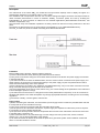
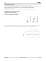
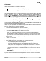
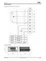
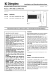
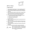
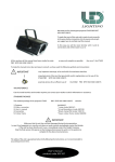
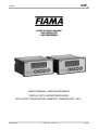
V4P_
&KURNC[
USER’S MANUAL AND MAINTENANCE
DISPLAY WITH MICROPROCESSOR
WITH INPUT FROM POTENTIOMETRIC TRANSDUCER "V4P_"
Data:13/07/04
Codice: V4P_ Rev.: 1.0
pag 1/7
V4P_
&KURNC[
Manual purpose
This manual has been designed by the Manufacturer to provide the necessary information regarding the
instrument to those who are authorized to carry out safely its installation, maintenance, dismantling and disposal.
All the necessary information for the buyers and planners can be found in the Sales catalogue. Other than
adopting good technical construction methods, the information should be read carefullyand strictly applied.
Inobservance of this information could cause risks for the health and safety of people and economical damage.
This information, provided by the Manufacturer in the original language(Italian) is also available in other languages
to satisfy legislative and/or commercial needs. This manual must be kept in a good condition by a responsible
person in an ideal place so that it is always available for consultation. In case this manual is lost or deteriorates, a
replacement should be requested directly from the manufacturer quoting the manual’s code. This manual reflects
the state of skill of the instrument at the time of input on the market: however the manufacturer reserves the right
to make changes, add or improve the manual without giving any reason to hold the present manual inadequate.
Identification of the equipment
The identification plate represented is applied to the instrument.
To find the identification code of the instrument, consult the sales catalogue.
Environmental conditions
Temperature setting: min. 0°C, max. + 50°C.
It is forbidden to use the instrument other than its specific use and in potentially explosive conditions or where antiexplo-sive elements are used.
Storage
Here below are some references to be followed for the storage of the instrument.
Avoid environments with excessive humidity and those exposed to bad weather (avoid open areas). Avoid putting
the instrument directly on the ground. Store the instrument in its original packing.
Conformity declaration and CEE marking
The instrument answers to the following Communitarian Directives:
2004/108/CEE
Electromagnetic compatibility, with reference to general Rules EN61000-6-2 (immunity in
industrial environment) and EN50081-1 (emission in residential environment),
2006/95/CEE
Low tension, modified Directive 93/68/CE.
Maintenance
Turn off the power before touching the internal parts.
Clean the external plastic parts using a soft, damp cloth with ethylic alcohol or water. Do not use hydrocarbon
solvents (petrols, diluants, etc.): using these products could affect the proper mechanical functioning of the
instrument.
Reparations should be done only and exclusively at the FIAMA technical assistance centre.
Calibrations and tests
It is advisable to calibrate the instrument periodically, once every working year.
To do the calibration, follow the calibration procedure indicated in the present manual .
Assistance request procedure
For any kind of technical assistance request, contact the sales department of the Manufacturer directly indicating
the information given on the identification plate, the number of hours used and the type of defect.
Manufacturer’s responsibility
The manufacturer declines any responsibility in case of :
• Using the instrument contrary to the national safety and accident-prevention laws.
• Wrong installation, inobservance or wrong procedures of the instructions provided in the present manual.
• Defective electrical power supply.
• Modifications or tamperings.
• Operations carried out by untrained or unqualified staff.
The safety of the instrument also depends on the strict observance of the procedures indicated in the manual:
always operate the instument in its functioning capacity and carry out a careful routine maintenance.
• All phases of inspection and maintenance should be done by qualified staff.
• The configurations provided in the manual are the only ones permitted.
• Do not try to use them anyway contrary to the indications provided.
• The instructions in this manual do not substitute but accomplish the obligations of the current legislation
regarding the safety laws.
Data:13/07/04
Codice: V4P_ Rev.: 1.0
pag 2/7
V4P_
&KURNC[
Description
The instruments of the series V4P_ are multifunction microprocessor displays used to display the signal of a
potentiometric transducer on a reading scale of -1999 + 9999.
The realization with microprocessor and the use of modern analogue-to-digital conversion techniques enable to
obtain excellent performances in terms of resolution, stability, conversion speed, and cost by enabling the
implementation of some functions of interest for the industrial applications (absolute/relative dimension, tool
diameter compensation, etc).
The instrument set-up and calibration operations are easily carried out with the four keys positioned on the front
panel.
The keeping of data when there is no power supply is guaranteed by a non volatile EEPROM memory.
The V4P_ is made of a panel box 48x96 conforming to the DIN 43700 standard.
Installation
Before installing the instrument, read the following warnings:
a) Connect the instrument strictly following the instructions of the manual.
b) Carry out the connections using the correct wires within the limits of the tension and power supply as indicated
in the technical data.
c) The instrument does not have an ON/OFF switch, hence it comes on when connected to the power supply. For
safety reasons, the equipment connected permanently to the power supply requires a bi-phasal selector switch
which should be within easy reach of the operator.
d) If the instrument is connected to any apparatus not isolated electrically, carry out an earth connection to avoid it
being connected directly through the structure of the machine.
d) It is the responsibility of the user to check, before using , the correct settings of the parameters of the instrument
to avoid damage to persons or things.
e) The instrument cannot function in a dangerous environment (inflammable or explosive). It can be connected to
elements that operate in the same atmosphere only through appropriate interfaces, according to the current safety
regulations.
g) Avoid dust, humidity, corrosive gases, heat sources.
Power supply
a) Before connecting the instrument, check that the the power supply tension is within the permitted limits and that
it corresponds to the one indicated on the tag.
b) Carry out the electrical connections with the instrument disconnected.
c) For the power line to instruments and sensors, a power supply line separate from that of the power is required :
it is necessary to use an isolating transformer.
d) The power line should provide a device that separates the set fuses of the instruments and should not be used
to regulate relays, contactors, etc.
e) If the network tension is very disordered (eg. from the change-over of the power units, motors, inverters,
welders, etc.), use the appropriate filters of the network.
f) If an earth connection is needed, ensure that the plant has a good earth system: tension between neutral and
earth <1V and the resistance <6 Ohm.
Data:13/07/04
Codice: V4P_ Rev.: 1.0
pag 3/7
V4P_
&KURNC[
Connections entries and exits
a) Physically separate the entry wires from those of the power supply, the exits, and the power connections; use
twined and shielded wires with the display connected to the earth only at one point.
b) Connect the exits of adjustments, alarms (meters, electrovalves, motors, ventilators, etc.) assembling units RC
(resistance and condenser in series) parallel to the charged inductives that work alternatively.
Assembly of the instrument
To carry out the correct installation of the instrument, it is necessary to follow the shown procedure:
1. Insert the instrument in the opening provided.
2. Screw the screw on the fixing block.
3. Hook the block to the instrument through the joints.
4. Block the instrument by screwing the screws of the two blocks.
5. Then carry out the electrical connections.
To assemble several instruments placed side by side, it is necessary to follow the interaxes as shown in the
design.The articles A and B can be read under space dimensions found in the present manual.
Data:13/07/04
Codice: V4P_ Rev.: 1.0
pag 4/7
V4P_
&KURNC[
Programming
The keys used to programme the instrument are the following:
PGM
RESET/ENTER
to enter and leave the programming phase,
to increase the digit under modification (blinking digit),
to move the blinking digit to the left,
to confirm the entered data.
In the programming phase a set-up parameter is characterised by a label (1 character) and by a value. When
the label is displayed, by pressing the
key the programme switches to the following parameter; by
pressing instead the RESET/ENTER key the currently set value for the selected parameter is displayed. By
pressing the
key the programme switches to the following parameter; by pressing instead the
key the
label is displayed again; by pressing again the RESET/ENTER key the value modification phase is entered.
The digit that is to be modified is the blinking one: by pressing the
key it is increased (once reached the
key the blinking digit to
maximum value for that digit the programme re-starts from zero). By pressing the
be modified is switched to the left. By pressing the RESET/ENTER key the parameters modifications are
confirmed and the following parameter label is displayed.
When the label is displayed by pressing the
key it is possible to leave the programming mode.
In order to enter the programming mode it is necessary to hold down the PGM key for some seconds. This
enables to avoid entering the programming mode accidentally.
The first value to be entered is that of the password: introduce the ‘273’ value and confirm; in case of wrong
value, the programming is left. After introducing the correct password it is possible to enter the modification of
the instrument set-up parameters.
In sequence, the parameters to be modified are the following:
1: intervention dimension of the first relay; (not used in this version)
2: intervention dimension of the second relay; (not used in this version)
3: intervention dimension of the third relay; (not used in this version)
r: use mode of the RESET/ENTER key in the ordinary functioning phase:
- if 0: RESET/ENTER key ignored;
- if 1: RESET/ENTER key used to zero set the dimension and switch from the absolute to the relative
display; when the same key is pressed again the programme goes back to the absolute dimension.
The relative dimension indication is represented by the switching on of the decimal point on the last digit
and it is very useful to carry out relative measures between any points of the instrument reading interval.
H: Hysteresis on the intervention of the relays (not used for this version)
O: offset (-1999 9999) to correct the displayed dimension; parameter used to counterbalance for instance the
thick ness of a tool;
I: selection of the type of input:
- 0 potentiometer
- 1, 2, 3, 4, 5, etc (not to be used in this version)
d: number of decimal digits (possible values: 0,1,2,3)
A: first calibration points; to carry out the calibration, carry out the following procedure:
- move the potentiometer to the first calibration point input;
specify the corresponding value to be displayed by editing the value corresponding to the A label in the
usual way;
- the calibration (potentiometer position and value to be displayed in that point) is validated in the
moment when the value to be displayed in the modification phase (one digit blinking) is confirmed by
pressing the RESET/ENTER key.
b: second calibration point; to carry out the calibration comply with the following procedure:
- move the potentiometer to the second calibration point input;
- specify the corresponding value to be displayed by editing the value corresponding to the b label in the
usual way;
- the calibration (potentiometer position and value to be displayed in that point) is validated in the moment
when the value to be displayed in the modification phase (one digit blinking) is confirmed by pressing the
RESET/ENTER key.
NB: The two calibration points must not necessarily be the beginning and the end of scale; any two points within
the potentiometer input scale can be taken as calibration points.
Data:13/07/04
Codice: V4P_ Rev.: 1.0
pag 5/7
V4P_
&KURNC[
Wiring Diagram
Potentiometric Transducer input (1-50 kOhm)
Overall dimensions
Data:13/07/04
Codice: V4P_ Rev.: 1.0
pag 6/7
V4P_
&KURNC[
Technical features
Power supply
Mains frequency
Absorbed power
Display
Resolution
Linearity
Thermal stability
Sampling time
Digital filter delay
Potentiometer input
Use temperature
Relative humidity
Self-extinguishible shock-resistant box
Size (with terminal box)
Drilling template
Degree of front protection of the box
Electromagnetic compatibility
115Vac, 230Vac, 24Vac, 12÷25Vdc ±10%
50/60 Hz
4VA
-1999 +9999
8000 points
0.1% f.s. at ambient temperature (25°C)
60 ppm/°C max
20ms
160ms
1K, 50K Ohm
0-50 °C
35-85%
DIN 43700
48x96x95 mm
45x92 mm
IP54
EEC 2004/108
Manufacturer
All communications to the manufacturer should be addressed to:
FIAMA s.r.l., Via G. Di Vittorio, 5/A - 43016 San Pancrazio (Parma) - Italy
Tel. (+39) 0521.672.341 - Fax. (+39) 0521.672.537 – e-mail: [email protected] - www.fiama.it
FIAMA srl is not responsible for any damage to persons or things caused by tamperings and wrong use
and in any case that are not consistent with the features of the instrument.
Data:13/07/04
Codice: V4P_ Rev.: 1.0
pag 7/7