1
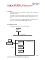
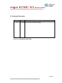
migra SC/MC 5/3
ModbusRTU
Large Format, Graphics Compatible Display with ModbusRTU Interface
User’s Manual
Distribuidor en España :
FEMA ELECTRÓNICA, SA
Pol. Ind. Santiga – Altimira 14 (T14 N2)
08210 Barberà del Vallès – BARCELONA
Tel. 93.729.6004 – [email protected]
Fax 93.729.6003 – w w w .fema.es
migra SC/MC 5/3 ModbusRTU
Large Format, Graphics Compatible Display with ModbusRTU Interface
Index
1
GENERAL
3
2
SYSTEM OVERVIEW
3
3
MODBUSRTU INTERFACE
4
3.1
Display Control Via ModbusRTU
5
3.2
Example
7
3.3
Connector Pin Assignments
3.3.1 External Connections
3.3.2 Internal LEDs and Switches
4
VERSIONS OVERVIEW
8
8
10
13
Page 2
microSYST Systemelectronic GmbH, Zur Centralwerkstätte 10, D-92637 Weiden, Germany
Tel. (+49- 961) 3 91 66-0, Fax (+49-9 61) 3 91 66-10, www.microsyst.de, [email protected]
migra SC/MC 5/3 ModbusRTU
Large Format, Graphics Compatible Display with ModbusRTU Interface
1 General
This display is based on the „migra SC/MC 5/3 Serial“, which is expanded by a
ModbusRTU interface.
The interface is used for the connection to a ModbusRTU controller (PLC) at
one side and the data exchange (RS485 frames) to the display at the other
side.
The frames for the display correspond to those of the „serial MIGRA“ and are
described in the User’s Manual „migra SC/MC 5/3 Serial“.
2 System Overview
The display is controlled with a ModbusRTU interface.
PLC
Modbus RTU
Gateway
PC for
configuration
RS232
migra Modbus RTU
Modbus RTU /
RS485
RS485
RS232
Controller
Board
Display
Modules
Page 3
microSYST Systemelectronic GmbH, Zur Centralwerkstätte 10, D-92637 Weiden, Germany
Tel. (+49- 961) 3 91 66-0, Fax (+49-9 61) 3 91 66-10, www.microsyst.de, [email protected]
migra SC/MC 5/3 ModbusRTU
Large Format, Graphics Compatible Display with ModbusRTU Interface
3 ModbusRTU Interface
The internal interface is the „ Modbus RTU Serial Gateway“ of the company
HMS (AB7010). At the enclosed compact disc you can find the documentation
and the necessary configuration software. Alternatively, you can find the files
at the home page of HMS (www.anybus.com).
The connectors for the configuration (RS232) and the controlling via ModbusRTU are accessible from the outside.
Page 4
microSYST Systemelectronic GmbH, Zur Centralwerkstätte 10, D-92637 Weiden, Germany
Tel. (+49- 961) 3 91 66-0, Fax (+49-9 61) 3 91 66-10, www.microsyst.de, [email protected]
migra SC/MC 5/3 ModbusRTU
Large Format, Graphics Compatible Display with ModbusRTU Interface
3.1 Display Control Via ModbusRTU
The display represents a ModbusRTU-Slave and is controlled by a ModbusRTUMaster (f.e. a PLC).
To change the display contents, the ModbusRTU-Master has to write to some
Registers. Therefore the commands “Force Multiple Registers” (function code
16d=10H) or “Read/Write Registers” (function code 23d=17H) can be used.
Here we assume that “Registers” are counted beginning at “0”. If your PLC starts
counting at “1” you may have to increase the register-address by 1!
The frames, which are described in the user’s manual „migra SC/MC 5/3 Serial“
(„02 81 80 8X DATA-Unit 03“), must be entered in the ModbusRTU output data
as follows:
Register
(Output)
0400H HIGH
LOW
0401H HIGH
HMS
memory
address
200H
201H
202H
LOW
0402H HIGH
LOW
0403H HIGH
LOW
203H
204H
205H
206H
207H
0404H HIGH
LOW
0405H HIGH
LOW
…
HIGH
…
LOW
Contents
Description
0
0
XX
Control register HIGH: static 0!
Control register LOW: static 0!
Trigger byte: The transmission of the frame is
executed with an increasing by one
Length byte: frame length
MIGRA frame „STX“ (static)
MIGRA frame „DA“ (static)
MIGRA frame „SA“ (static)
MIGRA frame „FC“:
0x80 = „without response“,
0x81 = „with response“
MIGRA frame „Data unit, 1st Byte“
MIGRA frame „Data unit, 2nd Byte“
MIGRA frame „Data unit, 3rd Byte“
…
MIGRA frame „Data unit, nth Byte“
MIGRA frame „ETX” (static)
6... n+5
02H
81H
80H
80H
or
81H
208H
XX
209H
XX
20AH
XX
…
XX
208H + (n-1) XX
208H + n
03H
The length byte and the MIGRA frame must be entered first. Then, the trigger byte
must be increased by one.
Thereby, the entered frame is transmitted to the MIGRA.
If the controlling happens without response frame („FC“ = 80H), the respectively
next frame must be sent approx. 100 to 200 ms soonest!
If you use the response („FC“ = 81H), the respectively next frame may be sent immediately after receiving the response!
Page 5
microSYST Systemelectronic GmbH, Zur Centralwerkstätte 10, D-92637 Weiden, Germany
Tel. (+49- 961) 3 91 66-0, Fax (+49-9 61) 3 91 66-10, www.microsyst.de, [email protected]
migra SC/MC 5/3 ModbusRTU
Large Format, Graphics Compatible Display with ModbusRTU Interface
A possible response appears in the Modbus RTU input data:
Register
(Input)
Contents
Description
0000H HIGH
LOW
0001H HIGH
HMS
memory
address
000H
001H
002H
0x9F
0
XX
LOW
0002H HIGH
LOW
0003H HIGH
LOW
0004H HIGH
LOW
0005H HIGH
LOW
…
HIGH
…
LOW
003H
004H
005H
006H
007H
008H
009H
00AH
…
008H + (n-1)
08H + n
n+5
02H
80H
81H
80H
XX
XX
XX
XX
XX
03H
Status register HIGH: without meaning!
Status register LOW: without meaning!
Trigger byte: Is increased by 1 value after the
reception of every response frame
Length byte: response length
MIGRA response „STX“ (static)
MIGRA response „DA“ (static)
MIGRA response „SA“ (static)
MIGRA response „FC“ (static)
MIGRA response „Data unit, 1st Byte“
MIGRA response „Data unit, 2nd Byte“
MIGRA response „Data unit, 3rd Byte“
…
MIGRA response „Data unit, nth Byte“
MIGRA response „ETX” (static)
The “Data unit” usually consists only of one byte (30H).
Note:
In most cases, you do not need the response frame!
The necessary frame intervals, which depend on the effort for the evaluation, can
also be found by trying.
Page 6
microSYST Systemelectronic GmbH, Zur Centralwerkstätte 10, D-92637 Weiden, Germany
Tel. (+49- 961) 3 91 66-0, Fax (+49-9 61) 3 91 66-10, www.microsyst.de, [email protected]
migra SC/MC 5/3 ModbusRTU
Large Format, Graphics Compatible Display with ModbusRTU Interface
3.2 Example
The online text „microSYST“ shall be shown at the display (without response):
ModbusRTU Output Data:
Register
(Output)
0400H HIGH
LOW
0401H HIGH
HMS
memory
address
200H
201H
202H
LOW
0402H HIGH
LOW
0403H HIGH
LOW
0404H HIGH
LOW
0405H HIGH
LOW
0406H HIGH
LOW
0407H HIGH
LOW
0408H HIGH
LOW
203H
204H
205H
206H
207H
208H
209H
20AH
20BH
20CH
20DH
20EH
20FH
210H
211H
Contents
Description
0
0
x
↓
x+1
Control register HIGH: static 0!
Control register LOW: static 0!
Trigger byte: The transmission of the frame is
executed with an increasing by one (after the
entries in HMS memory address 203H ... 211H
have been done!)
Length byte: frame length
MIGRA frame „STX“ (static)
MIGRA frame „DA“ (static)
MIGRA frame „SA“ (static)
MIGRA frame „FC“ (without response)
=’m”
=’i’
=’c’
=’r’
=’o’
=’S’
=’Y’
=’S’
=’T’
MIGRA frame „ETX” (static)
14
02H
81H
80H
80H
6DH
69H
63H
72H
6FH
53H
59H
53H
54H
03H
Page 7
microSYST Systemelectronic GmbH, Zur Centralwerkstätte 10, D-92637 Weiden, Germany
Tel. (+49- 961) 3 91 66-0, Fax (+49-9 61) 3 91 66-10, www.microsyst.de, [email protected]
migra SC/MC 5/3 ModbusRTU
Large Format, Graphics Compatible Display with ModbusRTU Interface
3.3 Connector Pin Assignments
3.3.1 External Connections
9pol. Sub-D Female Connector “ModbusRTU”
Pin
1
2
3
4
5
6
7
8
9
Assignment
RS-232 TxD
RS-232 RxD
GND Bus
+5V Bus Out
RS-485 D0 (Rx/Tx-)
RS-485 D1 (Rx/Tx+)
Remark: Depending on DIP5 of the ModbusRTU-interface (see below) either
the RS232-pins or the RS485-pins may be used. The unused pins have to be
left open. Do not use a standard RS232-cable where all pins are connected.
Otherwise the ModbusRTU-interface may be destroyed!!!
9pol. Sub-D Male Connector “RS232 migra”
Pin
1
2
3
4
5
6
7
8
9
Assignment
RxD
TxD
GND
This connector serves for the configuration of the migra display.
Page 8
microSYST Systemelectronic GmbH, Zur Centralwerkstätte 10, D-92637 Weiden, Germany
Tel. (+49- 961) 3 91 66-0, Fax (+49-9 61) 3 91 66-10, www.microsyst.de, [email protected]
migra SC/MC 5/3 ModbusRTU
Large Format, Graphics Compatible Display with ModbusRTU Interface
9pol. Sub-D Male Connector “Modbus Config”
Pin
1
2
3
4
5
6
7
8
9
Assignment
RxD
TxD
GND
Remark: This connector should not be used by the customer! The configuration is already done by microSYST and must not be changed! Otherwise the
correct function of the display can not be guaranteed!
7pol. Mains Plug (230 VAC)
Pin
1
2
(PE)
Assignment
L1
N
PE
Page 9
microSYST Systemelectronic GmbH, Zur Centralwerkstätte 10, D-92637 Weiden, Germany
Tel. (+49- 961) 3 91 66-0, Fax (+49-9 61) 3 91 66-10, www.microsyst.de, [email protected]
migra SC/MC 5/3 ModbusRTU
Large Format, Graphics Compatible Display with ModbusRTU Interface
3.3.2 Internal LEDs and Switches
1
2
3
4
5
6
LED
1 - Bus Error
2 - Bus Ready
3 – Processing
4 – HW Settings
5 - Subnet Status
6 - Device Status
State
Off
Description
Normal operation
Red
Off
Green
Red
Off
Bus error; CRC mismatch >10%
Not powered
Normal operation (bus ready)
Bus is off line (bus not ready)
Currently not processing query
Currently processing query
Normal operation
Not configured
Power off
Initializing and not running
Running
Stopped or subnet error, or timeout
Power off
Invalid or missing configuration
Initializing
Configuration OK
Green, flashing
Off
Red
Off
Green, flashing
Green
Red
Off
Alternating Red/Green
Green
Green, flashing
Page 10
microSYST Systemelectronic GmbH, Zur Centralwerkstätte 10, D-92637 Weiden, Germany
Tel. (+49- 961) 3 91 66-0, Fax (+49-9 61) 3 91 66-10, www.microsyst.de, [email protected]
migra SC/MC 5/3 ModbusRTU
Large Format, Graphics Compatible Display with ModbusRTU Interface
ModbusRTU
Node Address
Node Address
(reserved)
*1
2
…
126
127
* = Factory-Setting
DIP1
OFF
OFF
OFF
…
ON
ON
DIP2
OFF
OFF
OFF
…
ON
ON
DIP3
OFF
OFF
OFF
…
ON
ON
DIP4
OFF
OFF
OFF
…
ON
ON
DIP5
OFF
OFF
OFF
…
ON
ON
DIP6
OFF
OFF
ON
…
ON
ON
DIP7
OFF
ON
OFF
…
OFF
ON
ModbusRTU
Baudrate
Baudrate
(reserved)
1200 baud
2400 baud
4800 baud
9600 baud
* 19200 baud
38400 baud
57600 baud
* = Factory-Setting
DIP8
OFF
OFF
OFF
OFF
ON
ON
ON
ON
DIP1
OFF
OFF
ON
ON
OFF
OFF
ON
ON
DIP2
OFF
ON
OFF
ON
OFF
ON
OFF
ON
ModbusRTU
Parity & Stop Bits
Parity
(reserved)
* No parity, 2 stop bits
Even parity, 1 stop bit
Odd parity, 1 stop bit
* = Factory-Setting
DIP3
OFF
OFF
ON
ON
DIP4
OFF
ON
OFF
ON
ModbusRTU
Physical Interface
Interface Type
RS232
* RS485
* = Factory-Setting
DIP5
ON
OFF
Page 11
microSYST Systemelectronic GmbH, Zur Centralwerkstätte 10, D-92637 Weiden, Germany
Tel. (+49- 961) 3 91 66-0, Fax (+49-9 61) 3 91 66-10, www.microsyst.de, [email protected]
migra SC/MC 5/3 ModbusRTU
Large Format, Graphics Compatible Display with ModbusRTU Interface
Important note:
To change the setting of the DIP-switches obey the following order:
- disconnect the power supply
- open the housing
- open the dip switch protection cap (carefully - using a little srew driver)
- set the dip switches as desired
- close the dip switch protection cap
- close the housing
- reconnect the power supply
While the housing is open power may only be applied by qualified personnel and nothing has to be touched inside the housing at this time!
Otherwise electrical shock and danger to life may happen! Please be
careful!
Page 12
microSYST Systemelectronic GmbH, Zur Centralwerkstätte 10, D-92637 Weiden, Germany
Tel. (+49- 961) 3 91 66-0, Fax (+49-9 61) 3 91 66-10, www.microsyst.de, [email protected]
migra SC/MC 5/3 ModbusRTU
Large Format, Graphics Compatible Display with ModbusRTU Interface
4 Versions Overview
Version
Date
1.00
07.05.08
Remark, Description
Kreuzer, Nickl: Document created
Certified per DIN EN ISO 9001:2000.
Page 13
microSYST Systemelectronic GmbH, Zur Centralwerkstätte 10, D-92637 Weiden, Germany
Tel. (+49- 961) 3 91 66-0, Fax (+49-9 61) 3 91 66-10, www.microsyst.de, [email protected]