1
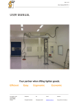
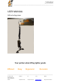
User manual - Side 1 of 14
AHR excluding gripper
User manual AHR V1.0.docx
_________________________________________________________________________________________________
USER MANUAL
AHR excluding gripper
Your partner when lifting lighter goods.
Efficient
Easy
Ergonomic
Economic
_________________________________________________________________________________________________
Air Handle e-p AB
Cedersdalsvägen 6 D
186 40 VALLENTUNA
Sweden
Telephone
Fax
E-mail
Website
+46 (0)8-511 873 02
+46 (0)8-511 873 04
[email protected]
http://www.air-handle.se
User manual - Side 2 of 14
AHR excluding gripper
User manual AHR V1.0.docx
_________________________________________________________________________________________________
TABLE OF CONTENTS
INTRODUCTION............................................................................................................................................................. 3
General instructions .................................................................................................................................................. 3
EC declaration of conformity CE................................................................................................................................. 5
GENERAL PRODUCT DATA ............................................................................................................................................. 6
Installation ................................................................................................................................................................ 6
Mechanical assembly ............................................................................................................................................ 6
Electrical installation ............................................................................................................................................. 6
Pneumatics ........................................................................................................................................................... 6
Inspection............................................................................................................................................................. 7
FUNCTION/FEATURE DESCRIPTION ................................................................................................................................ 7
SAFETY RULES ............................................................................................................................................................... 7
General safety rules................................................................................................................................................... 7
Product based security .............................................................................................................................................. 8
Safety control of the equipment ................................................................................................................................ 8
The hoists boot sequence .......................................................................................................................................... 9
OPERATING INSTRUCTION ............................................................................................................................................. 9
Label / stickers .........................................................................................................................................................11
SERVICE / MAINTENANCE .............................................................................................................................................11
Self-monitoring ........................................................................................................................................................11
Troubleshooting .......................................................................................................................................................12
Spare parts ...............................................................................................................................................................13
Recommended spare parts ..................................................................................................................................13
Service agreement ...............................................................................................................................................13
Drawings ......................................................................................................................................................................13
Wiring ......................................................................................................................................................................13
Pneumatic ................................................................................................................................................................13
ENCLOSURES ................................................................................................................................................................14
_________________________________________________________________________________________________
Air Handle e-p AB
Cedersdalsvägen 6 D
186 40 VALLENTUNA
Sweden
Telephone
Fax
E-mail
Website
+46 (0)8-511 873 02
+46 (0)8-511 873 04
[email protected]
http://www.air-handle.se
User manual - Side 3 of 14
AHR excluding gripper
User manual AHR V1.0.docx
_________________________________________________________________________________________________
INTRODUCTION
Dear Customer! Thank you for choosing a product from Air Handle e-p AB. Our goal is to create the most efficient and
simple solution to enable a valuable tool in your production. We hope you will be satisfied with your investment and
that it will help you raise your productivity and working environment.
If you have questions or comments of the product do not hesitate to contact us.
Technology: (The ability to more efficient goods handling)
We offer you hoist and handling solutions from a wide and deep knowledge
within several technical fields such as mechanics, hydraulics, pneumatics,
vacuum technology, electrical, electronics and computers.
EFFICIENT
Service: ( To easily achive and maintain efficient handling)
We can participate in your project preparation and propose several options on
the appropriate way to handle your goods. We also offer assembly, installation
and education. After the installation also offer to do maintenance and repairs
when needed or by a service agreement.
EASY
Ergonomics: (A prerequisite for efficient people)
ERGONOMIC
We offer simple, user friendly and properly designed hoist and handling
solutions that increase motivation, commitment and provide greater focus on
your product, reduced absence – a healthy and positive co-worker is the most
important asset.
Economic: (The result of the investment in hoist and handling equipment)
ECONOMIC
We offer hoist and handling equipment with a low total cost which quickly
provide a more efficient production and a quicker way to reach your goals..
GENERAL INSTRUCTIONS
Important! The manual must be read before the product is operated. Only
authorized personnel may use the equipment. To avoid accidents the manual
must be read and safety rules must be followed.
It is important for you as an operator and user of the equipment that you fully understand the equipment features.
Beware of any possible crush hazard when using the equipment.
Do not use the equipment if you notice any damages or abnormal functionality. Always report malfunctions to your
superior.
The equipment can only be used to what it is constructed for. All other use is improper and divest the manufacturer
from responsibility by the event of material and/or personal damage/injury that can result from such misuse.
The manufacturer’s instructions regarding working, maintenance and repairs must be followed thoroughly.
Accident prevention and other safety regulations must always be followed.
_________________________________________________________________________________________________
Air Handle e-p AB
Telephone
Fax
E-mail
Website
User manual - Side 4 of 14
AHR excluding gripper
User manual AHR V1.0.docx
_________________________________________________________________________________________________
Proper use, inspections, maintenance and maneuvering is crucial for working safety and will increase the equipments
lifetime.
The equipment covered by this manual can contain machine parts and/or components manufactured by subcontractors
therefore we refer to the following enclosures:
Enclosures
Reference manual for AH system Pnnn V1.0
Customer specification AHR
User manual for gripper
Schematic for gripper
These enclosures form basic documentation. Before you use the equipment you should read these documents as they
may contain important information that is not covered by this manual.
In the event of combining other products with the equipment, the data, descriptions and safety rules covered by this
manual is to be followed otherwise shall information covered in the enclosures be followed.
_________________________________________________________________________________________________
Air Handle e-p AB
Cedersdalsvägen 6 D
186 40 VALLENTUNA
Sweden
Telephone
Fax
E-mail
Website
+46 (0)8-511 873 02
+46 (0)8-511 873 04
[email protected]
http://www.air-handle.se
User manual - Side 5 of 14
AHR excluding gripper
User manual AHR V1.0.docx
_________________________________________________________________________________________________
EC DECLARATION OF CONFORMITY CE
Manufacturer/Supplier:
Air Handle e-p AB
Cedersdalsvägen 6 D
186 40 Vallentuna
Sweden
Tel: +46 (0)8 511 873 02
Fax: +46 (0)8 511 873 04
www.air-handle.se
Machine description:
AHR excluding gripper,
Conformity:
AFS 2009:5 ”Maskiner ”(AFS 2008:3)
Machinery directive 2006/42/EG
Low voltage directive 2006/95/EC
EMC directive 2004/108/EG
Standards:
(Where applicable)
EN 292-1, EN 292-2, EN 60204-1, IKH 4.30.01 edition 3
IKH 6.31.06, SS-ISO 5766
The equipment is manufactured and assembled completely or partially by Air Handle e-p AB, with
or without components or finished machine parts from subcontractors who have given assurance
that the current Machine Directive as described above has been followed. The equipment is hereby
declared to conform to existing machinery directive.
City:
Date:
Signature:
Clarification of signature:
_________________________________________________________________________________________________
Air Handle e-p AB
Telephone
Fax
E-mail
Website
User manual - Side 6 of 14
AHR excluding gripper
User manual AHR V1.0.docx
_________________________________________________________________________________________________
GENERAL PRODUCT DATA
See enclosure Customer specification AHR
INSTALLATION
Check that the delivered goods are not damaged before assembly/installation. Also check that all parts, fasteners,
necessary tools and mounting equipment are available to complete the installation. Contact Air Handle e-p AB if you
have any questions. Also see the enclosures:
Enclosures
Reference manual for AH system Pnnn V1.0
Customer specification AHR
User manual for gripper
Schematic for gripper
Before you use the equipment for the first time:
If education is necessary it is normally performed along with the installation.
MECHANICAL ASSEMBLY
The equipment is assembled by personnel from Air Handle e-p AB.
ELECTRICAL INSTALLATION
If the equipment has been delivered with a wall-plug, the equipment can be deployed by a non authorized electrician.
The wall-plug must be connected to grounded electrical outlet of 230V 6A.
If the equipment has been delivered with a circuit breaker / electrical cabinet, then the electrical installation must be
done by an authorized electrician – one (1) phase 230V 6A, this electrical junction is the customers responsibility.
PNEUMATICS
The equipment is delivered with a connection to a compressed air supply in form of a quick connect coupling (CEJN).
The equipment needs 6 bar operating pressure with a capacity of at least 600 Nl/min of dry and clean compressed air.
We recommend a filter regulator with pressure gauge of appropriate size is mounted adjacent to the equipment.
_________________________________________________________________________________________________
Air Handle e-p AB
Cedersdalsvägen 6 D
186 40 VALLENTUNA
Sweden
Telephone
Fax
E-mail
Website
+46 (0)8-511 873 02
+46 (0)8-511 873 04
[email protected]
http://www.air-handle.se
User manual - Side 7 of 14
AHR excluding gripper
User manual AHR V1.0.docx
_________________________________________________________________________________________________
INSPECTION
The equipment does not need an assembly inspection according to regulations. We still recommend that the
equipment is inspected by an accredited company. This is to ensure that the final installation is done correctly and the
equipment is safe to use. If you do not know how to get in contact with such company we can help to convey this
contact.
FUNCTION/FEATURE DESCRIPTION
The equipment is a helping tool to lift and/or transport loads, from approx. 5kg up to the maximum capacity stated for
that particular equipment, in a way that do not harm the human body. To move the load up or down you use the hoists
handle, moving the handle up or down creates a signal to the hoists control system and it will raise or lower the load
accordingly to the signal – only a force of a few hundred grams are needed to drive maximum loads. The force placed
on the handle is proportional to the speed of the hoist.
The hoist can be balanced, this is when you release the handle and the signal becomes zero (neutral) the load can be
maneuvered by taken hold of the load itself and when pulled up or pushed down the hoist will help raise/lower the
load as if you was controlling it by the handle. This operation is slower than when operating by handle but is good when
the load needs to fit into tight places, you can easy use both hands to steer the load in position both sideways as
up/down.
SAFETY RULES
GENERAL SAFETY RULES
Gentle handling, regular maintenance and cleaning reduce maintenance costs and the risk for downtime, and make the
work both enjoyable and safer.
Air Handle´s products may only be operated by authorized and instructed personnel.
Remember that you as a user is responsible for no one to get hurt!
•
•
•
•
•
•
•
•
•
•
Only use the equipment to what it is intended to.
The hoist is NOT for lifting persons.
No one should walk/be under suspended loads.
Use the equipment calmly, carefully and with attention.
Do not overload the equipment.
Work Environment Authority shall be followed.
Inspections, service and repairs should be performed by qualified personnel. A custom modification deprives
the manufacturer responsibility for any injury or accident.
Check that the equipment is in good condition in the beginning of each shift.
Report to management if you detect any defects do not use the equipment until it is fully functional again.
The operator must keep full attention on the equipment all times a load is handled.
_________________________________________________________________________________________________
Air Handle e-p AB
Cedersdalsvägen 6 D
186 40 VALLENTUNA
Sweden
Telephone
Fax
E-mail
Website
+46 (0)8-511 873 02
+46 (0)8-511 873 04
[email protected]
http://www.air-handle.se
User manual - Side 8 of 14
AHR excluding gripper
User manual AHR V1.0.docx
_________________________________________________________________________________________________
Beware of crushing hazards when working near machinery!
Employers are obliged to ensure that the equipment is used by skilled personnel and that inspections and maintenance
of the equipment is carried out as required.
PRODUCT BASED SECURITY
•
•
•
The equipment can only be used for what it is intended to.
Maximum load – see the document ”Customer specification AHR” – see maximum load for gripper in the
manual for the gripper (if such is delivered).
Do not ever leave the system with suspended loads.
SAFETY CONTROL OF THE EQUIPMENT
Before daily use…
•
Always check that the equipment and it’s safety features are intact
•
Check wire wear
• Check that compressed air and electricity is connected to the equipment
• Check that the signal hose is properly connected to the maneuver handle
• Check that the gripper tool is securely connected to the hoist’s junction
1.
2.
Run down the hoist as far as it is possible. Check the wire for wear, do not work with damage wire
Fit in the gripper tool to the object that shall be lifted – depending of the gripper tool there are several ways to
continue the safety control…
2.1. Mechanical gripper tool – the gripper consist of a hook, loop or similar, make sure the grip is correct and give
a signal upward with the maneuver handle, the object is now following up or down and can be handled
weightless.
2.2. Gripper tool with grip/release interlocking – the gripper consist of mechanics that can be moved when
activating a electrical push button, ButtonFunction, that is located somewhere on/near the gripper tool
1.
This type of gripper tool often has a LED that is indicating when it is possible to activate the
ButtonFunction button. There is a pressure level, ReleaseOk, and it is only below this level where the
ButtonFunction button can be activated i.e. when the gripper tool has no object (empty – no load) the
LED is lit but when an object is about to be lifted the LED goes out.
2.
Fit in the gripper tool to the object that shall be lifted and press the button for activating grip- or release
function (ButtonFunction).
3.
Carefully give a signal upward with the maneuver handle until the LED goes out.
4.
If the LED is not lit when the hoist’s system pressure is below ReleaseOk then the LED is broken / the
cabling is loose in some junction point / the cabling is broken / the input is broken on the controller card.
The interlock is not depending of if the LED is lit or not, the LED is only an indication that it is POSSIBLE to
grip/release, the interlock depends if the hoist’s air pressure is over or under ReleaseOk.
2.3. Gripper tool with grip/release and grip ok interlock
1.
Somewhere on the gripper tool there is one or more sensors that shall ensure that the object is
correct fitted to the gripper tool, try now to grip the object but in a way that NOT every grip ok
sensors is activated – this way you will not get a GripOk signal, push the grip button – carefully
give a signal upward with the maneuver handle, when the air pressure in the hoist’s system raises
above the level set with ReleaseOk the hoist stops going upward – this is because the GripOk
signal is missing. Check all sensors – these should be connected in serial or AND:ed to ensure
safety.
_________________________________________________________________________________________________
Air Handle e-p AB
Telephone
Fax
E-mail
Website
User manual - Side 9 of 14
AHR excluding gripper
User manual AHR V1.0.docx
_________________________________________________________________________________________________
2.
3.
4.
Put down the lift object and ensure that all GripOk signals are correct. The hoist can now be
operated as normal.
3.
Check grip- release interlocking according to paragraph 2.2.
Check MaxPressure by adding weight to the hoist when the lifting object is hanging in the gripper tool, the hoist
will stop going further up when the air pressure in the hoist system is over the level MaxPressure.
Run the hoist as far up as possible. If you do not reached the height you are supposed to, there may be some
mechanical interference or someone has changed a parameter i the controller card – see Troubleshooting.
THE HOISTS BOOT SEQUENCE
If the hoist system by any reason should get the power shut off or if the compressed air will disappear and there is load in
the gripper tool, something of the following will happen if the power/compressed air do not return.
1.
2.
3.
Compressed air will slowly leak out from the hoist system and the gripper tool will descent to the nearest
surface, if the gripper tool lands on e.g. the edge of a table, the hoist will have support for a while but
eventually the gripper tool will fall off the edge and will because of that pick up speed sideways as well – make
sure the surface is firm and that there is no obstacles.
The gripper tool uses vacuum to hold the load, these vacuum tools can be leaking slow to very fast depending
of vacuum tool – the load can fall out rather quick.
The gripper tool uses cylinders/other pneumatic and the compressed air will leak out slow.
When the hoist system is started, the system starts in 2 different ways, this depends if interlocking is used or not. If
parameter P03 (ReleaseOk) is set to zero(0), then there is no interlocking and the system will start without diagnosing its
current state. If a value is set for parameter P03 and the air pressure is higher than this value, the system will activate
the grip-valve in an attempt to secure the lift object NOTE. There is no guarantee that the grip is correct at this time,
the lift object can have slipped out of its proper position – be aware of any abnormality when the system is started with
load in the gripper tool. The system align to its current state automatically i.e. it does not matter if you use grip/release
or hover/grip/release function (P07 (ButtonFunction)) - the system will start with the grip phase.
If the air pressure in the system is lower than the set value for P03 the lift is ready to use as normal.
OPERATING INSTRUCTION
All maneuvers must be performed carefully. Make sure that no-one is under suspended load.
Switch on the equipment, the circuit breaker can be placed on or nearby the equipment, the electrical connection can
also be a simple wall plug. As soon as the equipment is powered the hoist is active, this is indicated by a bar and digits
are lit (green) in the display on the hoist’s left side.
In normal mode the digits show how many lift cycles there are remaining to next
maintenance, the digits show how many cycles in percent of 250.000 cycles e.g. –22 means
that there are 22 percent of 250 000 lift cycles left (55000).
The bars indicate the signal from the handle. Bar upside – up signal, bar in the middle –
handle I neutral position (no pushing or pulling), bar downside – down signal.
If the hoist is equipped with a gripper tool that has interlock functions, these interlock functions must be checked
before use – see Safety control of the equipment.
The maneuver handle responds to the hands push/pull movement and the handle must be moved gentle, small
movements results in low speed of the hoist and large movements’ results in high speed. The pictures below show 2
ways of how to hold the handle.
_________________________________________________________________________________________________
Air Handle e-p AB
Telephone
Fax
E-mail
Website
User manual - Side 10 of 14
AHR excluding gripper
User manual AHR V1.0.docx
_________________________________________________________________________________________________
Using the whole hand gives big movements and
therefore a high lifting speed of the hoist, this grip
can be used when handling not fragile goods.
If you relieve the carpus and give small, precise
movements with your fingertips the hoist will move
with a low and controlled speed, this grip is good
when handling fragile goods, fitting the lift object
when assembly, fixtures e.t.c.
Run the hoist to the desired height using the handle. Move the gripper tool to the object that will be lifted/operated, if
the gripper is composed by a hook or loop, fit it on the object and start to gently run the hoist upward by the handle –
the hoist is now moving upward and lifting the object.
If the gripper is more complex with grip/release functions, fit the gripper to the object and activate (push) the grip
button – see enclosed manual for gripper tool. Gently pull the handle upward and the hoist goes upward lifting the
object.
Run the hoist to the desired height and move the goods to the desired location, push gentle the handle down to lower
– the hoist moves downward.
To release the object the hoist need to be unloaded i.e. air pressure in the hoist system must be down to a level where
the hoist do not start to go up when the object is released. When a mechanical gripper tool is used you often need to
continue down before the gripper tool, hook or loop, can be released from the object. Is a gripper tool with interlock
used, the hoist need to be below the ReleaseOk parameter to release the object – see enclosed manual for gripper tool.
The hoist can be configured to balance the lift object. When the handle signal is zero i.e. in neutral position, you can
after a programmed interval, 30-100ms, take a hold on the lifting object an pull/push this up/down and hereby get the
hoist to follow you movements – this type of control is a bit slower than using the handle. When the hoist is balanced
you can easily steer the object to its destination – note, to be able to release the hoist need to be unloaded which it can
not be when it is balanced.
Do NOT leave the hoist with a lift object in the gripper tool. When the equipment is shut down, the air in the system
will slowly lead out through e.g. cylinder seal and the hoist will sink to its most lower position (or where it may find a
support to lean against). If load is in the gripper tool and external air supply is shut off then possible vacuum system can
stop functioning and the load can fall out of gripper tool.
_________________________________________________________________________________________________
Air Handle e-p AB
Telephone
Fax
E-mail
Website
User manual - Side 11 of 14
AHR excluding gripper
User manual AHR V1.0.docx
_________________________________________________________________________________________________
LABEL / STICKERS
Pay attention to warning and note signs. Do not lift more than stated by the MAXIMUM LOAD sign- overload may
damage the equipment, both hoist and gripper tool – the gripper tool can be dimensioned for considerable lower
weights compared to what the hoist is capable of – see the grippers maximum load in its manual.
SERVICE / MAINTENANCE
If the following checkpoints are not performed, Air Handle can not guarantee that the product is safe to use. Also the
lifetime of the product can be significant reduced.
SELF-MONITORING
Interval
Action
Daily:
•
•
Check that the media spiral from the handle up to the nose of the hoist is not damage,
check that all connectors are intact and check for wearage.
Run the hoist to its minimum and maximum position – check that it runs smoothly and that
everything seems normal.
Run the hoist down to its minimum position and check the wire do not is damage or
showing signs of wear.
Make a visual control of the equipment – check that it looks ok.
•
•
Wipe away dirt and clean the working surfaces.
Make sure all signs are visible (maximum load, crushing hazards etc.).
•
Listen for abnormal sounds when using the equipment.
•
•
•
•
Check that all bolts are tightened.
Make a test lift with full load.
Thoroughly inspect the media spiral and wire.
Check the parameters in the controller card (release levels, max levels etc), do a function
test according to Safety control of the equipment.
•
•
Weekly:
Monthly:
Annual:
You should also keep the equipment clean. Wipe with damp cloth and mild detergent, like dish washing liquid.
If there is a service manual or service protocol delivered with the equipment, these must be filed with ongoing actions
that documents checkpoints and maintenance.
_________________________________________________________________________________________________
Air Handle e-p AB
Cedersdalsvägen 6 D
186 40 VALLENTUNA
Sweden
Telephone
Fax
E-mail
Website
+46 (0)8-511 873 02
+46 (0)8-511 873 04
[email protected]
http://www.air-handle.se
User manual - Side 12 of 14
AHR excluding gripper
User manual AHR V1.0.docx
_________________________________________________________________________________________________
Extended information about service/maintenance can also be found in these enclosures:
Enclosures
Reference manual for AH system Pnnn V1.0
Customer specification AHR
User manual for gripper
Schematic for gripper
TROUBLESHOOTING
NOTE! Wrong or maladjusted settings can cause serious damage to both people and equipment. Actions that require
modifications to the equipment can only be done by authorized personnel. Beware of electrical safety, working with
equipment that is connected to the power line must be performed by an authorized electrician.
Error
Possible cause
Action
The hoist do not start at
all
Failure of power supply
Check that the display of the hoist’s left side
is showing digits, check that the circuit
breaker is on, check fuses.
No stroke
Failure of air supply
Check compressed air connection, wrinkles
on tubing, check that there is pressure in
the air supply system
Error of signal between handle and
controller system
Check tubing between handle and controller
system
The safety belt has been activated
Run the hoist all down, you may help pull
some wire out by hand – the safety belt will
no release its lock, give gentle signal upward
Jerky liftning motion.
Error of signal between handle and
controller system
Hoist slows down.
Leakage in signal between handle and
controller system
Check the bar indication on the hoist’s left
side. Up signal – bar at upper position.
Down signal – bar at lower position. Bars
in middle – handle in neutral position, no
signal
Check tubing between handle and
controller system, check the membrane
for damages
If errors can not be resolved by this troubleshooting guide, contact Air Handle or representative for service/repair. To
be able to provide faster service, please refer to this manuals order number User manual AHR V1.0.docx.
_________________________________________________________________________________________________
Air Handle e-p AB
Cedersdalsvägen 6 D
186 40 VALLENTUNA
Sweden
Telephone
Fax
E-mail
Website
+46 (0)8-511 873 02
+46 (0)8-511 873 04
[email protected]
http://www.air-handle.se
User manual - Side 13 of 14
AHR excluding gripper
User manual AHR V1.0.docx
_________________________________________________________________________________________________
SPARE PARTS
Only use original parts for replacement and repairs. If other parts or components are used the warranty expires. If you
have any doubts of how service/repairs should be performed, we recommend that it is carried out by Air Handle or
represents.
When ordering spare parts please refer to specified article name and number, and this manuals order number User
manual AHR V1.0.docx.
A complete spare part list can be found in Reference manual for AH system Pnnn V1.0. Also see enclosures for
equipment delivered along with the AHR system.
RECOMMENDED SPARE PARTS
You do, of course, an own evaluation of how important this equipment is for your production, and what an eventual
stoppage would imply. Contact us for a discussion and evaluation of proper spare parts for your specific needs.
We do recommend that you at least have following spare parts to minimize stoppage.
•
•
E1074-01, wire 3x4,5x10m
I1001-02, membrane
SERVICE AGREEMENT
Please contact us if you are interested in a service agreement for this product.
We check all the safety features and perform a complete functional check. The equipment is cleaned and lubricated if
necessary. Worn parts are repaired/replaced in order to keep the equipment in good condition. You will receive a
protocol of performed actions. You will then automatically be assisted in your ongoing process of control in the work
environment for this equipment.
DRAWING S
See enclosure Reference manual for AH system Pnnn V1.0
WIRING
See enclosure Reference manual for AH system Pnnn V1.0
PNEUMATIC
See enclosure Reference manual for AH system Pnnn V1.0 and any enclosures delivered with this equipment
_________________________________________________________________________________________________
Air Handle e-p AB
Cedersdalsvägen 6 D
186 40 VALLENTUNA
Sweden
Telephone
Fax
E-mail
Website
+46 (0)8-511 873 02
+46 (0)8-511 873 04
[email protected]
http://www.air-handle.se
User manual - Side 14 of 14
AHR excluding gripper
User manual AHR V1.0.docx
_________________________________________________________________________________________________
ENCLOSURES
Enclosures
Reference manual for AH system Pnnn V1.0
Customer specification AHR
User manual for gripper
Schematic for gripper
_________________________________________________________________________________________________
Air Handle e-p AB
Cedersdalsvägen 6 D
186 40 VALLENTUNA
Sweden
Telephone
Fax
E-mail
Website
+46 (0)8-511 873 02
+46 (0)8-511 873 04
[email protected]
http://www.air-handle.se