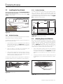
1
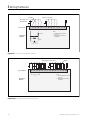
S7-I/O Input/Output Device
Operator’s Manual
Manual No. SGOM-6138A
IMPORTANT
The information contained herein is general in nature and not intended for specific application purposes. It does not relieve the user of responsibility to use
sound practices in application, installation, operation, and maintenance of the
equipment purchased. Siemens reserves the right to make changes at any time
without notice or obligations. Should a conflict arise between the general information contained in this publication and the contents of drawings or supplementary material, or both, the latter shall take precedence.
QUALIFIED PERSON
For the purposes of this manual, a qualified person is one who is familiar with the
installation, construction, or operation of the equipment and the hazards
involved. In addition, this person has the following qualifications:
(a) is trained and authorized to de-energize, clear, ground, and tag circuits
and equipment in accordance with established safety practices.
(b) is trained in the proper care and use of protective equipment such as rubber gloves, hard hat, safety glasses or face shields, flash clothing, etc., in
accordance with established safety procedures.
(c) is trained in rendering first aid.
DANGER
For the purpose of this manual and the product lables, DANGER indicates an
imminently hazardous situation which, if not avoided, could result in death or
serious injury.
WARNING
For the purpose of this manual and the product lables, WARNING indicates a
potentially hazardous situation which, if not avoided, could result in death or
serious injury.
CAUTION
For the purpose of this manual and the product lables, CAUTION indicates an
potentially hazardous situation which, if not avoided, could result in minor or
moderate injury.
Contents
1 Introduction........................................ 1
1.1
1.2
1.3
1.4
Product Summary .................................. 1
Applications............................................ 1
Features ................................................. 1
Where to Find More Information ............ 1
2 Product Overview .............................. 3
2.1
2.2
Hardware Overview ................................ 3
2.1.1 Base Module ............................. 3
2.1.2 Expansion Modules................... 3
2.1.3 SEAbus Communications ......... 3
Software Overview ................................. 3
2.2.1 WinPM Software........................ 3
3 Installing Modules ............................. 5
3.1
3.2
3.3
3.4
Installation Guidelines ............................ 5
Installing the Base Module ..................... 6
3.2.1 DIN Rail Mounting ..................... 6
3.2.2 Surface Mounting ...................... 6
Attaching Expansion Modules ............... 6
Removing Expansion Modules............... 7
4 Wiring the Device .............................. 9
4.1
4.2
4.3
4.4
Wiring Guidelines ................................... 9
Wiring Suppression Circuits ................. 10
4.2.1 AC Relay Output Suppression 10
4.2.2 DC Transistor Output
Suppression ............................ 10
4.2.3 Communications Wiring .......... 10
4.2.4 Input and Output Numbering .. 11
4.2.5 Signal (I/O) Wiring.................... 11
Analog Input Wiring.............................. 16
4.3.1 Typical Application .................. 16
Power Requirements............................ 17
6.3.1
6.3.2
Viewing Status Lights .............. 23
Viewing Device Status ............. 24
A Technical Specifications .................25
A.1
A.2
A.3
A.4
A.5
A.6
A.7
A.8
A.9
General Standards ............................... 25
General Specifications ........................ 26
S7-I/O-DC Base Module w/DC Power
Supply, DC Inputs, and DC Outputs ... 27
S7-I/O-AC Base Module
w/AC Power Supply, DC Inputs, and
Relay Outputs ...................................... 28
Expansion Module (Optional),
8 DC Digital Inputs .............................. 29
Expansion Module (Optional),
8 AC Digital Inputs ............................... 29
Expansion Module (Optional),
8 DC Digital Outputs ........................... 30
Expansion Module (Optional),
8 Relay Outputs ................................... 30
Expansion Module (Optional),
3 Analog Inputs ................................... 31
B EC Standards for Electromagnetic
Compatibility ...................................33
C Current Budget ................................34
5 Configuring the Device ................... 19
5.1
5.2
5.3
5.4
5.5
5.6
Overview .............................................. 19
Setting the Device Address.................. 19
Configuring Outputs............................. 19
Naming Inputs and Outputs ................. 20
Configuring Alarms............................... 20
5.5.1 Overview.................................. 20
5.5.2 Triggering an Alarm ................. 20
5.5.3 Alarming on Counter ............... 21
5.5.4 Alarming on Any State Change 21
5.5.5 Alarming on Particular State
Change .................................... 21
5.5.6 Controlling Output Based on
Alarms ..................................... 21
Configuring Diagrams .......................... 21
6 Controlling the Device .................... 23
6.1
6.2
6.3
Automatic Control ................................ 23
Manual Control..................................... 23
Viewing S7-I/O Status .......................... 23
Siemens Energy & Automation, Inc.
i
NOTE
These instructions do not purport to cover all details
or variations in equipment, nor to provide for every
possible contingency to be met in connection with
installation, operation, or maintenance. Should further
information be desired or should particular problems
arise which are not covered sufficiently for the purchaser’s purposes, the matter should be referred to
the local sales office.
The contents of the instruction manual shall not
become part of or modify any prior or existing agreement, commitment or relationship. The sales contract
contains the entire obligation of Siemens Energy &
Automation, Inc. The warranty contained in the contract between parties is the sole warranty of Siemens
Energy & Automation, Inc. Any statements contained
herein do not create new warranties or modify the
existing warranty.
ii
Siemens Energy & Automation, Inc.
1 Introduction
1 Introduction
•
Monitoring alarm status
1.1
•
Opening and closing of breakers remotely
•
Providing other remote control and communications
functions
Product Summary
The S7-I/O device is an addressable modular input/output
(I/O) device that links power system components to the
ACCESS™ electrical distribution communication system.
The device can monitor or control components that are not
specifically designed for digital communication.
1.3
Features
The S7-I/O device is the link between the ACCESS electrical
distribution communication system and the rest of the
power system. It provides the following features:
•
14 digital inputs and 10 digital outputs on the base unit.
•
I/O capability in blocks of 8 up to a total of 54 inputs or
50 outputs.
•
On-board control power for expansion modules.
•
Counters on the first 8 inputs of the base unit.
•
Pulsed or latched digital states on outputs (Pulsed outputs can be used for breaker operation control).
•
Relay contact outputs that can be controlled manually.
•
Capability of using dry contacts as inputs (Signal voltage is provided through the internal power supply).
The S7-I/O device operates as a field device on the
ACCESS communications system. It has a digital address
and is polled on a regular schedule by a supervisory computer. The supervisory equipment can be either a PC, a
PLC, or other compatible supervisory device. Speed of
response depends on the number of field devices connected to the 485 communications loop.
•
Capability of accepting external power at 120 VAC,
240 VAC, or 24 VDC.
•
Standard DB-9 connection port for connection to an
RS-485 network.
•
Analog input capability up to a total of 12 inputs.
Connection to the ACCESS system is self-contained. An
RS-485 serial link is used to communicate counter data,
event log data, and the status of inputs and outputs. In
addition, the S7-I/O device allows manual control of all outputs via WinPM.
1.4
1.2
•
S7-I/O SEAbus Protocol Reference Manual
•
WinPM Software User’s Manual
•
ACCESS System Installation Guide
SF
I 0.0
I 1.0
Q 0.0
Q 1.0
RUN
I 0.1
I 1.1
Q 0.1
Q 1.1
STOP
I 0.2
I 1.2
Q 0.2
I 0.3
I 1.3
Q 0.3
I 0.4
I 1.4
Q 0.4
I 0.5
I 1.5
Q 0.5
SIMATIC
S7-200
I 0.6
Q 0.6
I 0.7
Q 0.7
CPU 214
X2
34
6ES7 214-1CC00-0XB0
Figure 1.1 S7-I/O Device
The S7-I/O device is designed for use with WinPM™, Siemens’ Microsoft Windows™-based power monitoring and
control software. The device communicates with a supervisory computer running WinPM by way of the SEAbus communications protocol.
Applications
The S7-I/O device can remotely monitor any device
equipped with an auxiliary contact, such as a molded case
circuit breaker or transformer temperature relay. This capability makes it particularly useful in applications that require
monitoring or controlling power system elements that are
not specifically designed for digital communications. It can
also be used to count and communicate the pulsed output
from a kilowatt-hour meter.
Where to Find More Information
This manual contains information on installing, connecting,
maintaining, and using the S7-I/O device within the
ACCESS system. Other sources of information are:
Outputs from the device have a variety of uses, such as
closing contactors, tripping circuit breakers, providing
remote indication, and providing various degrees of alarming.
Typical applications of the S7-I/O device include
•
Reporting transformer winding temperature
•
Monitoring breaker status
Siemens Energy & Automation, Inc.
3
1 Introduction
Notes:
4
Siemens Energy & Automation, Inc.
2 Product Overview
2 Product Overview
2.1
Hardware Overview
2.1.1
Base Module
The S7-I/O base module is enclosed in a compact, modular
case. This case encloses the central processing unit, power
supply, and discrete inputs and outputs. The device may be
either panel mounted or mounted on a DIN rail. The device
is designed for natural convection cooling.
Two models of the S7-I/O base module are available: one
with AC control power, relay outputs, and type 1 sinking DC
inputs, and one with DC control power, sourcing transistor
outputs, and type 1 sinking DC inputs. The AC control
power model is powered by an 85–264 VAC source at 47–
63 Hz, allowing it to be used in a wide range of locations
where the AC power supply is assured. The DC control
power model is powered by a user-supplied, external, 24
VDC nominal power source, such as a battery. This power
source is ideal in locations where using AC is impractical or
where AC power is likely to be interrupted.
The base module supports up to 14 digital inputs and 10
digital outputs. Expansion modules can be used to provide
additional inputs and outputs. Each digital expansion module provides either 8 inputs or 8 outputs. Each analog
expansion module provides 3 inputs. Up to 4 analog modules and up to any combination of five input and output
modules can be added.
2.1.2
Expansion Modules
Expansion modules increase the number of inputs or outputs the S7-I/O device can monitor and control. A maximum
of five digital modules or 4 analog modules, each attached
to the side of the other, can be used with one S7-I/O base
module. When digital and analog modules are used in combination, there can be up to 5 digital and 2 analog modules.
Expansion modules include:
•
Digital Input (AC Power)
•
Digital Input (DC Power)
•
Relay Output (AC Power)
•
Contact Output (DC Power)
•
Analog Input (see section 4.3)
Siemens Energy & Automation, Inc.
2.1.3
SEAbus Communications
The S7-I/O device is integrated into the ACCESS system
through its RS-485 communications capability. Up to 32
ACCESS devices, including S7-I/O devices, power meters,
protective relays, and trip devices, can be connected on
one communications loop. Using the SEAbus protocol,
devices can be attached to a loop of twisted-pair cabling up
to 4000 feet long. Four loops can connect to a supervisory
computer via an Isolated Multi-Drop converter (RS-232 to
RS-485). The supervisory computer monitors and controls
devices on the network, including the S7-I/O device, using
WinPM software or other supervisory software. This software is described in the next section.
2.2
Software Overview
2.2.1
WinPM Software
The S7-I/O device can be programmed and controlled from
an IBM-compatible personal computer running WinPM
supervisory software. WinPM software is sold separately. In
addition to the S7-I/O device, WinPM monitors and controls
power meters, protection relays, and trip devices in the
ACCESS system. This software includes the following features:
•
Configuration of outputs as pulsed or latched, including
pulse duration
•
Descriptive labeling of inputs, outputs, and I/O state
names
•
Remote monitoring of system data in real time
•
Logged events and alarms based on input status,
counters, and output activation
•
Graphical display of input and output status and
counters
•
Graphical buttons to control outputs
•
Export of live and historical data to other programs
Refer to Chapter 5 for a discussion of how WinPM software
configures the device. Refer to Chapter 6 for a discussion of
how WinPM software monitors and controls the S7-I/O
device.
5
2 Product Overview
Notes:
6
Siemens Energy & Automation, Inc.
3 Installing Modules
3 Installing Modules
This section describes how to install the base module and
the expansion modules.
7.75 in.
(197 mm)
2.4 in.
(62 mm)
3.15 in.
(80 mm)
Base Module
3.54 in.
(90 mm)
2.4 in.
(62 mm)
3.15 in.
(80 mm)
Expansion Module
3.1
Installation Guidelines
The S7-I/O device is designed either to be snapped onto a
standard DIN rail (DIN EN 50 022) or to be surface mounted.
Figure 3.1 shows dimensions for the DIN rail and Figure
3.2 shows physical dimensions of the base module.
.039 in.
(1.0 mm)
1.38 in.
(35 mm)
0.2 in.
(5 mm)
Figure 3.2 Physical Dimensions
A minimum panel depth of 75 mm (2.9 inches) is required to
mount the S7-I/O device inside a panel. Users who are
installing expansion modules, need an additional 25 mm (1
inch) clearance on the left side of the base module and on
the right side of the last attached expansion module to
attach and remove the expansion modules. A clearance of
65mm (2.5 inches) above and below the S7-I/O device is
required for convection cooling.
1.0 in.
(25 mm)
0.29 in.
(7.5 mm)
Figure 3.1 DIN Rail Dimensions
Siemens Energy & Automation, Inc.
7
3 Installing Modules
3.2
Installing the Base Module
3.2.2
Before installing the base module, be sure that power is
disconnected and turned off. Also ensure that the mode
switch, located behind the top access door shown in Figure 3.3, is set to “RUN.”
Surface Mounting
To surface mount the S7-I/O device and expansion modules, 2 DIN M4 or American Standard #8 screws are
required per module. These screws are not provided. The
mounting holes are located behind the access covers at the
top and bottom edges of the front of the device. See Figure
3.5 for dimensions and locations.
Mode Switch in "RUN" Position
STOP
RUN
TERM
0
1
0.25 in.
(6.4mm)
7.25 in.
(184.3 mm)
0.50 in.
(12.8mm)
3.04 in.
(77.3 mm)
0.25 in.
(6.4mm)
2.65 in.
(67.3 mm)
Base
Module
Expansion
Module
Figure 3.3 Mode Switch
3.2.1
DIN Rail Mounting
Figure 3.5 Mounting Hole Locations
The S7-I/O device and expansion modules attach to the DIN
rail by means of clips, which are supplied.
To mount an S7-I/O base module or expansion module to a
DIN rail, follow these steps:
1.
Open the DIN rail clip(s) on the bottom of the device by
pulling them downward. See Figure 3.4, which shows
the clip positions. (Base units have two clips; expansion
modules have one.)
2.
Seat the device on the DIN rail by positioning the
groove on the back of the device over the rail.
3.
Hold the device against the rail and push the clip(s) up
to attach the module. Be sure the device is firmly
seated on the rail. A slight tug on the bottom of the unit
will ensure proper seating of the unit.
To remove the module, pull the clip(s) down. A small hole is
provided, allowing use of a screwdriver to aid the removal.
3.3
Attaching Expansion Modules
Base units and expansion modules all have a bus connector
on the right side for attachment of additional expansion
modules. The bus connector, included with the expansion
module, connects the modules. The bus connector is
shown in Figure 3.6. Before attaching an expansion module, the bus connector panel must first be removed. To
remove the bus connector panel, follow these steps.
1.
Insert a flat-bladed screwdriver into the space between
the bus connector panel and the S7-I/O base module
or expansion module case. See Figure 3.7 for proper
placement of the screwdriver. The cover is not replaceable.
2.
Gently pry off the bus connector panel, taking care not
to damage the case or other internal electronic components.
Clip Closed
Clip Open
Projections on Bottom
of Bus Connector
Figure 3.4 DIN Rail Clips
Figure 3.6 Expansion module bus connector
8
Siemens Energy & Automation, Inc.
3 Installing Modules
Circuit Board Expansion Module
Bus Connector
Base Module
Expansion Module
Figure 3.7 Removing the Bus Connector Panel
To attach an expansion module to the base module or to
another expansion module, follow these steps (See Figure
3.8 and Figure 3.9):
1.
2.
Plug the expansion module’s bus connector into the
bus connector slot on the left side of the expansion
module. Be sure the four projections on the bus connector face the back side of the module. These projections will snap on the module case.
Plug the expansion module into the right bus connector
of the receiving module. Be careful not to install expansion modules upside down. All expansion modules can
be installed in the field. Be sure the installation guidelines above are followed for each module to be
installed.
Figure 3.9 Proper Expansion Module Placement (Cutaway
View)
3.4
Removing Expansion Modules
To remove an expansion module for repair or replacement,
follow these steps:
1.
Remove power from all units.
2.
Disconnect all wiring from the module to be removed.
3.
Snap open the DIN rail clip, or remove the attachment
screws.
4.
Slide the device that is to be removed approximately 1
inch to the right to disconnect the bus connector.
Expansion Module
Bus Connector
Clips
Base Module
Expansion Module
Figure 3.8 Attachment of Expansion Module
Siemens Energy & Automation, Inc.
9
3 Installing Modules
Notes:
10
Siemens Energy & Automation, Inc.
4 Wiring the Device
4 Wiring the Device
4.1
inputs on an expansion module, or relay coils on an AC
relay output expansion module. The DC sensor supply
is short-circuit protected.
Wiring Guidelines
The following are general guidelines for wiring an S7-I/O
device.
•
Connect all ground terminals to the closest available
earth ground to provide the greatest immunity from
noise. If possible, connect all ground terminals on the
base and expansion units to a common point. Use 14
AWG (1.5 mm²) wire.
The following guidelines apply to using a DC power supply
with the DC base module.
•
Ensure the DC power supply has sufficient surge
capacity to maintain voltage during sudden load
changes. Additional external capacitance may be
required.
•
For ungrounded DC power supplies, connect a resistor
and capacitor in parallel from the power source common to ground. The resistor (1 MΩ typical) provides a
leakage path to prevent static charge accumulation.
The capacitor (4700 pf typical) provides a drain for
high-frequency noise. A grounded DC system may also
be created by connecting the power source common
directly to ground. See Figure 4.1 below.
AC Power
Line
Neutral
Ground
DC Power Supply
AC
DC
Users should:
•
Follow all applicable electrical codes when wiring and
operating equipment connected to the S7-I/O device.
•
Use the shortest wiring runs possible.
•
Avoid placing I/O wiring near power conductors.
•
Equip I/O wiring with surge suppression devices if used
in areas subject to lightning surges.
1 MΩ
Typical
4700 pf
Typical
Base Module
•
Provide a single disconnect switch that removes power
from the device and all inputs and outputs.
•
Provide overcurrent protection to the device, inputs,
and outputs. Each output can be fused for further protection. External overcurrent protection for the inputs is
not required when the 24 VDC internal supply is used.
•
The DC sensor supply from the base module may be
used to supply power for the base module inputs, DC
Siemens Energy & Automation, Inc.
Figure 4.1 DC Supply connection
11
4 Wiring the Device
4.2
Wiring Suppression Circuits
Equip inductive output loads with suppression circuits
(snubbers) that limit the voltage rise on turn off. Use the following guidelines. Note that the effectiveness of a given
design is dependent on the application, and its adequacy
must be verified. Be sure that all components are rated for
use in the application.
4.2.1
+VDC
AC Relay Output Suppression
When using a relay or AC output to switch 115 V/230 VAC
loads, place RC snubbers across the relay contacts or the
AC switch as shown in Figure 4.2 below. Use a metal oxide
varistor (MOV) to limit peak voltage. Ensure that the working
voltage of the MOV is at least 20% greater than the nominal
line voltage.
Inductor
S7-I/O
+VDC
R
MOV
C
Inductor
S7-I/O
Inductor
S7-I/O
Figure 4.3 DC Loads with Diodes Across Load
Figure 4.2 AC Load with Snubber Across Relay
4.2.2
DC Transistor Output Suppression
The S7-I/O DC outputs contain zener diode snubbers that
may be adequate for your application. Use external suppression diodes for large or frequently switched inductive
loads to prevent overpowering the internal diodes.
Note: Do not use RC snubbers.
See Figure 4.3.
4.2.3
Communications Wiring
The S7-I/O device is designed to be connected to the
ACCESS system by means of a SEAbus RS-485 connection. This is a shielded twisted-pair connection that uses the
communications port at the bottom of the S7-I/O base unit.
The preferred method to connect ACCESS devices is a
loop, so that a break in the cable will not prevent communications. Refer to the ACCESS Systems Installation Guide
(Manual No. SG-6028) for detailed instructions for wiring
devices.
RS-485 connections are made with shielded twisted pair
cable. The data wires are labeled “Transmit/Receive +” and
“Transmit/Receive -,” and are wired in parallel. Connect the
shield at one end of the communications link only.
The pinouts of the cable provided with the S7-I/O device is
shown in Figure 4.4.
12
Siemens Energy & Automation, Inc.
4 Wiring the Device
4.2.5
1
2
6
3
7
4
8
5
Signal (Input and Output) Wiring
Be sure power is turned off and disconnected before installing field wiring.
9
Pin
Function
1
3
5
8
Logic Ground
Tx/Rx +
Logic Ground
Tx/Rx -
Figure 4.4 Communication Cable Pinouts
4.2.4
Input and Output Numbering
The input and output (I/O) terminals on the device are numbered to provide unique identification of each I/O signal. The
base module inputs are named I0.0 through I0.7 and I1.0
through I1.5. The base module outputs are named Q0.0
through Q0.7 and Q1.0 through Q1.1.
To wire input and output control and power supply terminals, follow these steps:
Siemens Energy & Automation, Inc.
1.
Use 14 to 22 AWG (0.5 to 1.5 mm²) wire.
2.
Identify and route wires from field points to the S7-I/O
device. Be sure the wires have proper strain relief at the
S7-I/O device. To identify the proper terminals, see Figures 4.5 through 4.11 on the following pages. Refer to
connector labels under the access covers of the S7-I/O
device.
3.
Insert wires and tighten terminal screws. Do not overtighten.
13
4 Wiring the Device
Loads
24 VDC External
Power Supply
Outputs (20.4–28.8 VDC)
+
+
+
Top: Outputs
1M 1L+ 0.0 0.1 0.2 0.3 0.4 2M 2L+ 0.5 0.6 0.7 1.0 1.1
Base
Module
470 Ω
•
Gnd M
L+
Note:
1. Actual component values
may vary.
2. Each ground connection
is optional.
+
3.3 KΩ
1M 0.0 0.1 0.2 0.3 0.4 0.5 0.6 0.7 2M 1.0 1.1 1.2 1.3 1.4 1.5
M
24 VDC
L+
Bottom: Inputs
+
+
Contacts
24 VDC Power for
Input Sensors or
Expansion Modules
(280 mA)
Inputs (15–35 VDC)
Figure 4.5 DC Base Module (DC Power Supply, DC inputs, DC Outputs)
Loads
AC External
Power Supply
(120 or 240 VAC)
Outputs (30 VDC/250 VAC)
N(-)
N(-)
N(-)
L(+)
L(+)
L(+)
Top: Outputs
1L
0.0 0.1 0.2 0.3
•
2L
0.4 0.5 0.6
•
Base
Module
3L
0.7 1.0 1.1 Gnd N
470 Ω
L1
Note:
1. Actual component values
may vary.
2. Each ground connection
is optional.
3. Connect AC line to the L
terminal.
+
3.3 KΩ
1M 0.0 0.1 0.2 0.3 0.4 0.5 0.6 0.7 2M 1.0 1.1 1.2 1.3 1.4 1.5
M
24 VDC
L+
Bottom: Inputs
+
+
Contacts
Inputs (15–35 VDC)
24 VDC Power for
Input Sensors or
Expansion Modules
(280 mA)
Figure 4.6 AC Base Module (AC Power Supply, DC Inputs, Relay Outputs)
14
Siemens Energy & Automation, Inc.
4 Wiring the Device
Contacts
Inputs (79–135 VAC)
AC Power
Supply
Top: Inputs
N
•
.0
.1
.2
0.15 µF
.3
.4
.5
.6
.7
•
•
Gnd
Note:
1. Actual component values
may vary.
2. Each ground connection
is optional.
470 KΩ
Expansion
Module
•
3.3 KΩ
390 Ω
Figure 4.7 AC Input Expansion Module (Optional)
24 VDC to Power
the Relay Coil
Loads
Dry Contact Outputs (30 VDC/250 VAC)
N(-)
N(-)
L(+)
L(+)
+
Top: Outputs
M
L+ Gnd 1L
Expansion
Module
.0
.1
.2
.3
•
2L
.4
.5
.6
.7
Note:
1. Actual component values
may vary.
2. Each ground connection
is optional.
3. Connect AC line to the L
terminal.
Figure 4.8 AC Relay Output Expansion Module (Optional)
Siemens Energy & Automation, Inc.
15
4 Wiring the Device
Contacts
Inputs (15–35 VDC)
DC Supply from +
Base Module
+
Top: Inputs
1M
.0
.1
.2
.3
•
2M
.4
.5
.6
.7
•
•
Gnd
Note:
1. Actual component values
may vary.
2. Each ground connection
is optional.
3.3 KΩ
Expansion
Module
470 Ω
Figure 4.9 DC Input Expansion Module (Optional)
Loads
Outputs (20.4–28.8 VDC)
+
+
Top: Outputs
1M 1L+ .0
Expansion
Module
.1
.2
.3
•
2M 2L+ .4
.5
.6
.7 Gnd
Note:
1. Actual component values
may vary.
2. Each ground connection
is optional.
Figure 4.10 DC Output Expansion Module (Optional)
16
Siemens Energy & Automation, Inc.
4 Wiring the Device
Voltage Source Current Source
+
24 VDC Supply from
Base Module
Unused
Input
+
Top: Inputs
RA A+
A-
RB B+
B-
RC C+
C-
•
•
L+
M Gnd
Expansion
Module
Figure 4.11 Analog Input Expansion Module (Optional)
Siemens Energy & Automation, Inc.
17
4 Wiring the Device
4.3
Analog Input Wiring
4.3.1
The S7-I/O analog input module can accept a range of input
currents or voltages. Configuration switches and a calibration potentiometer are located on the bottom of the expansion module. Figure 4.12 shows the location of these
switches. They are accessed through the ventilation slots on
the bottom of the case.
Typical Application
Figure 4.13 displays a typical application for the S7-I/O.
To
Supervisiory
Computer
Isolated
Multi-Drop
Converter
S7-I/O With
Analog Expansion
Module
Gain
1
3
OFF
ON
Temperature
Transducer
For Monitoring Transformer
Winding Temperature
Analog Input Expansion Module
Figure 4.12 Configuration Switches and Potentiometer
S7-I/O With
Analog Expansion
Module
Table 4.1 shows how to configure the analog input expansion module.
For Monitoring Humidity in
Refrigeration Units
Table 4.1 Configuration Switches for the Analog Input
Expansion Module
Configuration Switch
18
Voltage or Current Range
1
3
ON
OFF
0–5 V
ON
OFF
0–20 mA
OFF
ON
0–10 V
Humidity
Transducer
Figure 4.13 Typical Application
Siemens Energy & Automation, Inc.
4 Wiring the Device
4.4
Power Requirements
The S7-I/O base modules have an internal power supply for
a variety of functions. This power supply provides power for
the base module, the expansion modules, and the inputs
and outputs. The expansion modules use 5 VDC power
supplied on the expansion bus. The base module provides
sufficient 5 VDC current to power five expansion modules.
The S7-I/O device power supply also provides 280 mA current at 24 VDC. This current is used to provide power for
itself and to provide power to the DC inputs. The following
table shows current consumption.
Table 4.2 Current Usage
S7-I/O Module
AC Base Module
Current Consumption, mA
(@ 24 VDC)
105
Current Consumption, mA
(@ 5 VDC)
340
DC Base Module
105
340
AC Digital Input Expansion Module
70
—
AC Digital Relay Output Expansion Module
85
801
DC Digital Input Expansion Module
60
60
DC Digital Output Expansion Module
85
80
Analog Input Expansion Module
60
15
1. Supply current for relay coil.
Siemens Energy & Automation, Inc.
19
4 Wiring the Device
Notes:
20
Siemens Energy & Automation, Inc.
5 Configuring the Device
5 Configuring the Device
5.1
Overview
The S7-I/O device can only be configured and controlled
through supervisory software. The discussion below
assumes that configuration of the S7-I/O device is done
from WinPM.
5.2
Setting the Device Address
Each device connected to an ACCESS system port must
have a unique SEAbus address in order to communicate
with the supervisory computer. The address is preset at the
factory to 222. If more than one S7-I/O device is connected
to the system, or if there is an address conflict with another
device in the system, the preset address will need to
changed. To set the device address, follow these steps:
1.
If there are any devices which can be configured manually, do so before using WinPM to configure them. This
will save time.
2.
Turn off power to all devices with conflicting addresses,
except the device to be re-configured.
3.
Start WinPM. If the communication port(s) and devices
have not already been configured, do so now. Refer to
the WinPM User’s Manual (Manual No. SG-6118) and
your ACCESS system documentation.
4.
Select the S7-I/O device from the device list whose
address is to be changed and click Edit. The Edit
Device dialog displays.
5.
6.
Enter a new address in the Address field and click
Change. Be sure the new address does not conflict
with any others on the same communication port.
Repeat steps 2 through 6 for all other S7-I/O addresses
that are to be changed.
Siemens Energy & Automation, Inc.
5.3
Configuring Outputs
The outputs of S7-I/O can be configured to be either pulsed
or latched. In addition, the pulsed outputs can be configured for pulse widths to any length of time from 100 ms and
up.
To configure the outputs, follow this procedure in WinPM:
1.
Select the S7-I/O device to be configured from the
Device List.
2.
Select Device Configuration from the Edit menu. The
Device Configuration dialog box displays.
3.
Click All Pulsed to configure all outputs as pulsed, or
click All Latched to configure all outputs as latched.
4.
To configure some outputs as pulsed and some as
latched, click on the individual output check boxes to
select or deselect them. A checked box indicates
pulsed operation, while an empty box indicates latched
operation.
5.
Enter a duration in the Pulse Width field after the outputs have been selected. Note that all pulsed outputs
must have the same pulse duration.
6.
Click Configure to send the configuration to the
S7-I/O device, or click Cancel to exit without changing
the configuration. Click Print to print out the configuration choices.
21
5 Configuring the Device
5.4
Naming Inputs and Outputs
5.5.2
Triggering an Alarm
In WinPM, meaningful names can be applied to inputs and
outputs, as well as to each of their on and off states.
To select the S7-I/O device to trigger an alarm, follow these
steps:
To change the names, follow these steps:
1.
Select Alarm from the Edit menu. The Alarm List displays.
2.
Click the Add button. The Alarm Limit Configuration
displays.
3.
Select the S7-I/O device from the Alarm Value:
Device list box .
1.
Select the S7-I/O device to be configured from the
Device List.
2.
Select Input/Output Naming from the Edit menu. The
I/O Names dialog displays.
3.
Select the register to rename from the Register list
box. Click the down arrow button to see the list of all
choices.
4.
Enter a new name, if desired, in the Name field.
5.
Select 1 or 0 from the State list box.
6.
Enter a new name for the state, if desired, in the State
Name field.
7.
Repeat steps 3 through 6 for all inputs and outputs that
are to be renamed.
8.
Click OK to save the choices and exit the dialog box.
Click Cancel to exit without making the changes.
The new names will appear in all windows and diagrams
within WinPM.
5.5
Configuring Alarms
5.5.1
Overview
Alarms can be configured in WinPM to do any or all of the
following:
•
Display an alarm message
•
Log an event in the Event log
•
Play a sound
•
Send a command to control a device, including operating an output and clearing a counter on a S7-I/O device
After selecting the S7-I/O device to be configured, alarm
conditions must be defined. Directions for defining alarm
conditions follow.
See the WinPM User’s Manual (Manual No. SG-6118) for
general directions on configuring alarms. The following information is specific to configuring alarms on S7-I/O inputs
and configuring S7-I/O outputs as alarm actions within
WinPM.
22
Siemens Energy & Automation, Inc.
5 Configuring the Device
5.5.3
To set an alarm when a S7-I/O device input counter
exceeds a certain value follow these steps:
1.
Select Type: High Limit from the Alarm Limit Configuration dialog box.
2.
Select the input counter register from the Alarm Value:
Register list box.
3.
Enter a value in the Alarm Value: Value field. When the
counter goes over this value, the alarm will occur.
5.5.4
•
Alarming on Counter
Alarming on Any State Change
To set an alarm when a S7-I/O device input changes state
follow these steps:
4.
5.6
Reset Output n to turn off an output
Where: n = 0 through 50
Repeat steps 2 and 3 to configure the Output When
Alarm Active section of the Alarm Limit Configuration dialog box.
Configuring Diagrams
S7-I/O device input status or counters can be displayed on
a system diagram in WinPM. A control button can also be
placed on a system diagram. This allows monitoring and
control of the system in a graphical environment. System
diagrams specifically for S7-I/O devices can contain the following:
•
Indicate the state of an input or output as a colored
graphic rectangle by using the binary element. Indicate
alarm states with different colors.
•
Indicate the status of an input or output by using the
numeric element. This element displays a label indicating the numeric value of an input counter or the “on”
and “off” states of an input or output. The names
defined in the Input/Output Naming dialog are displayed.
To set an alarm when a S7-I/O device input changes to a
particular state follow these steps:
•
Indicate the value of an analog input as a gauge by
using the analog element.
1.
Select Type: Equal to from the Alarm Limit Configuration dialog box.
•
Clear the input counter or turn an output on or off by
using the button element.
2.
Select the input register from the Alarm Value: Register list box.
Refer to the WinPM User’s Manual (Manual No. SG-6118)
for instructions on creating and configuring system diagrams.
3.
Enter the desired value to trigger the alarm in the Alarm
Value: Value field. If the on and off states were named
with different names using the Input/Output Naming
command, then use the new name for the alarm value.
When the input goes into this state, the alarm will
occur.
1.
2.
Select Type: Change from the Alarm Limit Configuration dialog box.
Select the input register from the Alarm Value: Register list box. Whenever the state of the input changes,
the alarm will occur.
5.5.5
5.5.6
Alarming on Particular State Change
Controlling Output Based on Alarms
To configure a S7-I/O device output as an alarm action follow these steps:
1.
Select the Action: Output check box from the Alarm
Limit Configuration dialog box.
2.
Select the S7-I/O device for which the alarm is to be
activated from the Output When Alarm Active:
Device list box.
3.
Select one of the following in the Output When Alarm
Active: Register list box.
•
Clear All Counters or Individually Clear Input
Counters 1 through 8
•
Set Output n to turn on an output
Where: n = 0 through 50
Siemens Energy & Automation, Inc.
23
5 Configuring the Device
Notes:
24
Siemens Energy & Automation, Inc.
6 Controlling the Device
6 Controlling the Device
6.3
6.1
The status of the S7-I/O device can be monitored both
locally at the device and remotely from a supervisory device.
Automatic Control
WinPM can automatically control an output or reset a
counter on an S7-I/O by using the configuration setup within
the Alarm List. See section 5.5.6 “Controlling Output
Based on Alarms” for information on configuring alarms to
perform actions.
6.2
Manual Control
Outputs can be manually controlled and input counters can
be manually cleared from WinPM.
To open or close an output, follow these steps:
1.
Select the S7-I/O device that is to be controlled from
the Device List window.
2.
Select Output Control from the Edit menu. The Output Control dialog box displays.
6.3.1
Viewing S7-I/O Status
Viewing Status Lights
Status light emitting diodes (LEDs) indicate power and operation of the device, as well as the current state for all inputs.
and outputs. These LEDs and their meanings are listed
below.
Table 6.1 Status LEDs
LED
Description
SF
(red)
System Fault. Contact the Siemens Factory for further
assistance. (See the final page of this manual for the
Siemens service request form)
RUN
(green)
Run mode. The RUN light indicates that the S7-I/O
device is running without problem.
STOP
(yellow)
Stop mode. The S7-I/O device should not normally go
into this mode unless the mode is switched to STOP.
I X.X
(green)
These LEDs indicate the current state of each input.
Q X.X
(green)
These LEDs indicate the current state of each output.
The following table lists the input and output numbers and
their labels on the status light display for the base module.
Table 6.2 Input and Output Labels for the Base Module
3.
Click the On or Off buttons to change the state of the
outputs. The current state is shown in the field to the
right. Any outputs that have been renamed with the
Input/Output Naming command will be displayed.
To clear input counters manually, use the Clear Settings
option from the Edit menu.
Input
Label
Output
Label
Input 1
I 0.0
Output 1
Q 0.0
Input 2
I 0.1
Output 2
Q 0.1
Input 3
I 0.2
Output 3
Q 0.2
Input 4
I 0.3
Output 4
Q 0.3
Input 5
I 0.4
Output 5
Q 0.4
Input 6
I 0.5
Output 6
Q 0.5
Input 7
I 0.6
Output 7
Q 0.6
Input 8
I 0.7
Output 8
Q 0.7
Input 9
I 1.0
Output 9
Q 1.0
Input 10
I 1.1
Output 10
Q 1.1
Input 11
I 1.2
Input 12
I 1.3
Input 13
I 1.4
Input 14
I 1.5
The starting address of expansion modules begin on the
next available whole number. For example, the first expansion module starting address would be x2.0 and the next
expansion module would start at x3.0.
Where:
x = I for input module or Q for output module.
Siemens Energy & Automation, Inc.
25
6 Controlling the Device
6.3.2
Viewing Device Status
To view the S7-I/O device status in WinPM, follow these
steps:
1.
3.
To view Min/Max data, select the S7-I/O device from
the Device List and click Min/Max... The Min/max
window displays.
Select Devices from the View menu. The Device List
displays.
The Min/max window displays when the inputs were
last turned on and off, as well as the highest values of
the input counters.
Of the three buttons on the right side of the Device List
window, only Realtime and Min/Max apply to the
S7-I/O.
2.
To change the parameters that appear on the Min/Max
window, select Edit from the Edit menu. The Edit
Min/Max window displays.
Select the desired S7-I/O device from the Device List,
and then click Realtime... The Real Time window displays.
Items that are highlighted are displayed on the Realtime window. To add a parameter, for display, select it
so that it is highlighted. To remove a parameter, select it
so it is no longer highlighted.
To change which parameters that appear on the Real
Time window, select Edit from the Edit menu. The
Real Time Edit window displays.
Items that are highlighted are displayed on the Realtime window. To add a parameter, for display, select it
so that it is highlighted. To remove a parameter, select it
so it is no longer highlighted.
26
Siemens Energy & Automation, Inc.
Appendix A: Technical Specifications
A Technical Specifications
A.1
General Standards
The national and international standards listed below were
used to determine appropriate performance specifications
and testing for the S7-I/O.
•
Underwriters Laboratories, Inc®: UL508 Listed (Industrial Control Equipment)
•
Canadian Standards Association: CSA C22.2 Number
142 Certified (Process Control Equipment)
•
VDE 0160: Electronic equipment for use in electrical
power installations
•
IEC 1131-2
requirements
•
European Community (CE) EMC Directive 89/336/EEC
•
Programmable
controllers–Equipment
Electromagnetic emission standards:
EN 50081-1: Residential, commercial, and light
industry
EN 50081-2: Industrial environment
•
Electromagnetic immunity standards:
EN 50082-2: Industrial environment
Siemens Energy & Automation, Inc.
27
Appendix A: Technical Specifications
A.2
General Specifications
The S7-I/O base and expansion modules conform to the following specifications:
Table A.1 Environmental Conditions—Transport and
Storage
Table A.4 Electromagnetic Compatibility—Conducted and
Radiated Emissions (EN 55011)1
Class A, Group 1, Conducted
0.15–0.5 MHz
Dry Heat and Cold
-40ºC to +70ºC
0.5–5 MHz
Damp Heat
25ºC to 55ºC, 95% humidity
5–30 MHz
Toppling
100 mm, 4 drops, unpacked
Free Fall
1 m, 5 times, packed for shipment
Class A, Group 1, Radiated
30 MHz–230 MHz
230 MHz–1 GHz
Table A.2 Environmental Conditions—Operating
Functional Range
0°C to 55°C, 95% maximum
non-condensing humidity
Temperature Ramp
5°C to 55°C, 3°C/minute
Mechanical Shock
15 G, 11 ms pulse, 6 shocks in
each of three axes
Sinusoidal Vibration
0.35 mm peak-to-peak 10–57
Hz; 2 G 57–150 Hz; 10 sweeps
each axis, 1 octave/minute
Mechanical protection
Protects against finger contact
with high voltage as tested by
standard probes. External protection is required for dust, dirt,
water, and foreign objects of
less than 12.5 mm in diameter.
Table A.3 Electromagnetic Compatibility—Immunity
Electrostatic Discharge
4 kV contact to terminals and
ground plane, 8 kV air discharge to all surfaces and
communication port
Radiated Electromagnetic
Field
26 MHZ–1 GHz 10 V/m, 80%
modulation with 1 kHz signal.
900 MHz ±5 MHz, 10 V/m
50% duty cycle, 200 Hz repetition frequency
Fast Transient Bursts
2 kV, 5 kHz with coupling network to AC and DC system
power. 2 kV, 5 kHz with coupling clamp to digital I/O and
communications
Surge Immunity
2 kV asymmetrical, 1 kV symmetrical, 5 positive / 5 negative
pulses 0º, +90º, -90º phase
angle. 24 VDC circuits require
external surge suppression
Non-Periodic Overvoltage
at 85 VAC line, 90° phase
angle, apply 390 V peak, 1.3
ms pulse.
at 180 VAC line, 90° phase
angle, apply 750 V peek, 1.3
ms pulse
28
Class B, Group 1, Conducted2
0.15–0.5 MHz
0.5–5 MHz
5–30 MHz
Class B, Group 1, Radiated2
30 MHz– 230 MHz
230 MHz–1 GHz
< 79 dB (µV) quasi-peak
< 66 db (µV) average
< 73 dB (µV) quasi-peak
< 60 db (µV) average
< 73 dB (µV) quasi-peak
< 60 db (µV) average
30 dB (mV/M) quasi-peak,
measured at 30 meters
37 dB (mV/M) quasi-peak,
measured at 30 meters
< 66 dB (µV) quasi-peak
decreasing with log frequency to 56 dB (µV)
< 56 dB (µV) average
decreasing with log frequency to 46 dB (µV)
< 56 dB (µV) quasi-peak
< 46 dB (µV) average
< 60 dB (µV) quasi-peak
< 50 dB (µV) average
30 dB (µV/m) quasi-peak
measured at 10 meters
37 dB (µV/m) quasi-peak
measured at 10 meters
1. Applicable for all devices bearing the CE (European Community) mark.
2. Unit must be mounted in a grounded metal enclosure. The AC
supply power line must be equipped with a Schaffner FN 6802.5/06 filter or equivalent.
Table A.5 High Potential Isolation Test
24 V/5 V Nominal Circuits
115/230 V Circuits to Ground
115/230 V Circuits to
115/230 V Circuits
230 V Circuits to
24 V/5 V Circuits
115V Circuits to
24 V/5 V Circuits
500 VDC (optical isolation
boundaries)
1500 VAC
1500 VAC
1500 VAC
1500 VAC
Siemens Energy & Automation, Inc.
Appendix A: Technical Specifications
A.3
S7-I/O-DC Base Module w/DC
Power Supply, DC Inputs, and DC
Outputs
Table A.6 General Features
Size: L x W x D
197 x 80 x 62 mm
(7.75 x 3.15 x 2.4 in.)
Weight
0.4 kg (0.9 lb.)
Power Dissipation
8 W at 3 A load
Maximum Inputs
14
Maximum Outputs
10
Maximum Expansion
Modules
7
Table A.9 Digital Outputs
Type
Sourcing Transistor
Voltage
24 VDC nominal
20.4–28.8 VDC
Maximum Load Current
Per Single Point
Per 2 Adjacent Points
All Points Total
0-40º C
0.75 A
1.00 A
4.00 A
55º C*
0.50 A
0.75 A
3.00 A
* Linear derate 40-55º C,
vertical mount derate 10º C
Inductive Load Clamping
Single Pulse
Repetitive
(per common)
2 A L/R = 10 ms
1 A L/R = 100 ms
1 W energy dissipation
(½Li² x switch rate < 1 W)
Leakage Current
100 µA
Switching Delay
25 µs on, 120 µs off
User supplied external
24 VDC nominal
20.4–28.8 VDC
non-isolated
Surge Current
4 A, 100ms
Voltage Drop
1.8 V maximum at maximum
current
Input Current
85 mA typical, CPU only
900 mA maximum load
Optical Isolation
500 VAC, 1 minute
Short Circuit Protection
none
UL/CSA Rating
50VA
Hold Up Time
10 ms minimum, from 24 VDC
Inrush Current
10 A peak @ 28.8 VDC
Fusing
1 A, 125 V, Slow Blow
non-replaceable
5 VDC Available Current
660 mA
DC Sensor Supply
16.4–28.8 VDC
280 mA available current
(<600 mA short circuit current
limit)
non-isolated
Ripple/noise <10Mhz same as
supplied voltage.
Table A.7 Power Supply
Voltage
Table A.8 Digital Inputs
Input Type
Type 1 Sinking
IEC 1131-2
On State
24 VDC nominal
15-30 VDC 4 mA minimum
35 VDC, 500 ms surge
Off State
5 VDC, 1 mA maximum
Response Time
0.2 ms maximum
Optical Isolation
500 VAC, 1 minute
Siemens Energy & Automation, Inc.
29
Appendix A: Technical Specifications
A.4
S7-I/O-AC Base Module
w/AC Power Supply, DC Inputs,
and Relay Outputs
Table A.10 General Features
Size: L x W x D
197 x 80 x 62 mm
(7.75 x 3.15 x 2.4 in.)
Table A.13 Digital Outputs
Type
Relay, dry contact
Voltage
5–30 VDC / 250 VAC
Maximum Load Current
2 A/point
Overcurrent Surge
7 A with contacts closed
Weight
0.5 kg (1.0 lb.)
Isolation Resistance
100 MΩ minimum (new)
Power Dissipation
9W
Switching Delay
10 ms maximum
Maximum Inputs
14
Lifetime
Maximum Outputs
10
10,000,000 mechanical
100,000 at rated load
Maximum Expansion
Modules
7
Table A.11 Power Supply
Voltage
85–264 VAC
Frequency
47–63 Hz
Input Current
4.5 VA typical, CPU only
50 VA maximum load
Hold Up Time
20 ms minimum / 110 VAC
Inrush Current
20 A peak @ 264 VAC
Fusing
2 A, 250 V, Slow Blow
non-replaceable
5 VDC Available Current
660 mA
Isolation
Transformer, 1500 VAC
1 Minute
DC Sensor Supply
20.4–28.8 VDC
280 mA available current (@24
VDC nominal)
(<600 mA short circuit current
limit)
non-isolated
Ripple/noise <10Mhz 1 V peak
to peak
Contact Resistance
200 mΩ maximum (new)
Isolation
coil to contact
contact to contact
1500 VAC, 1 minute
1000 VAC, 1 minute
Short Circuit Protection
none
Table A.12 Digital Inputs
Input Type
Type 1 Sinking
IEC 1131-2
On State
24 VDC nominal
15-30 VDC 4 mA minimum
35 VDC, 500 ms surge
Off State
5 VDC 1 mA maximum
Response Time
0.2 ms maximum
Optical Isolation
500 VAC, 1 minute
30
Siemens Energy & Automation, Inc.
Appendix A: Technical Specifications
A.5
Expansion Module (Optional),
8 DC Digital Inputs
Table A.14 General Features
A.6
Expansion Module (Optional),
8 AC Digital Inputs
Table A.17 General Features
Size: L x W x D
90 x 80 x 62 mm
(3.54 x 3.15 x2.4 in.)
Size: L x W x D
90 x 80 x 62 mm
(3.54 x 3.15 x 2.4 in.)
Weight
0.2 kg (0.4 lb.)
Weight
0.18 kg (0.39 lb.)
Power Dissipation
2W
Power Dissipation
2W
Maximum Inputs
8
Maximum Inputs
8
Table A.15 Digital Inputs
Table A.18 Digital Inputs
Input Type
Type 1 Sinking
IEC 1131-2
Input Type
Type 1 Sinking
IEC 1131-2
On State
24 VDC nominal
15-30 VDC 4 mA minimum
35 VDC, 500 ms surge
On State
120 VAC, 60 Hz, 7 mA nominal
79–135 VAC 47–63 Hz,
4 mA minimum
Off State
5 VDC 1 mA maximum
Off State
20 VAC 1 mA maximum
Response Time
3.5 ms typical
4.5 ms maximum
Response Time
15 ms maximum
Optical Isolation
1500 VAC, 1 minute
Optical Isolation
500 VAC, 1 minute
Table A.19 Current Requirements
Table A.16 Current Requirements
5 VDC Logic Current
5 VDC Logic Current
60 mA from base module
24 VDC Sensor Current
60 mA from base module or
external power supply
Siemens Energy & Automation, Inc.
70 mA from base module
31
Appendix A: Technical Specifications
A.7
Expansion Module (Optional),
8 DC Digital Outputs
Table A.20 General Features
A.8
Expansion Module (Optional),
8 Relay Outputs
Table A.23 General Features
Size: L x W x D
90 x 80 x 62 mm
(3.54 x 3.15 x 2.4 in.)
Size: L x W x D
90 x 80 x 62 mm
(3.54 x 3.15 x 2.4 in.)
Weight
0.2 kg (0.4 lb.)
Weight
0.2 kg (0.4 lb.)
Power Dissipation
4 W at 3 A load
Power Dissipation
3W
Maximum Outputs
8
Maximum Outputs
8
Table A.21 Digital Outputs
Table A.24 Digital Outputs
Type
Sourcing Transistor
Type
Relay, dry contact
Voltage
24 VDC nominal
20.4–28.8 VDC
Voltage
5–30 VDC / 250 VAC
Maximum Load Current
2 A/point
Overcurrent Surge
7 A with contacts closed
Isolation Resistance
100 MΩ minimum (new)
Switching Delay
10 ms maximum
Lifetime
10,000,000 mechanical
100,000 at rated load
Contact Resistance
200 mΩ maximum (new)
Isolation
coil to contact
contact to contact
1500 VAC, 1 minute
1000 VAC, 1 minute
Short Circuit Protection
none
Maximum Load Current
Per Single Point
Per 2 Adjacent Points
All Points Total
0-40º C
0.75 A
1.00 A
4.00 A
55º C*
0.50 A
0.75 A
3.00 A
* Linear derate 40-55º C,
vertical mount derate 10º C
Inductive Load Clamping
Single Pulse
Repetitive
(per common)
2 A L/R = 10 ms
1 A L/R = 100 ms
1 W energy dissipation
(½Li² x switch rate < 1 W)
Leakage Current
100 µA
Switching Delay
50 µs on, 200 µs off
Surge Current
4 A, 100ms
Voltage Drop
1.8 V maximum at maximum
current
Optical Isolation
500 VAC, 1 minute
5 VDC Logic Current
80 mA from base module
Short Circuit Protection
none
24 VDC Coil Current
85 mA from base module or
external power supply
Output Point Current
supplied by user at module
common
Table A.22 Current Requirements
5 VDC Logic Current
80 mA from base module
Output Point Current
supplied by user at module
common
32
Table A.25 Current Requirements
Siemens Energy & Automation, Inc.
Appendix A: Technical Specifications
A.9
Expansion Module (Optional),
3 Analog Inputs
Table A.26 General Features
Size: L x W x D
90 x 80 x 62 mm
(3.54 x 3.15 x 2.4 in.)
Weight
0.2 kg (0.4 lb.)
Power Dissipation
2W
Maximum Inputs
3
Indicator LED
Power supply fault,
low voltage, out-of-range
Table A.27 Analog Inputs
Isolation
Non-isolated
Analog-to-Digital
Conversion Time
25 µs
Analog Step Response
≤ 10 µs
Common Mode Rejection
40 dB, nominal at 50/60 Hz
Common Mode Voltage
≤ 12 V–signal value
Normal Mode Rejection
40 dB, nominal at 50/60 Hz
Data Word Format
Unipolar, Full-Scale
0–32000
Table A.28 Current Requirements
Table A.27 Analog Inputs
Type
Single ended
Input Impedance (+IN)
≥ 10 MΩ
Maximum Input Voltage
30 V
Maximum Input Current
32 mA
Resolution
12 bits or 0.025% of full scale
5 VDC Logic Current
70 mA from base module
External Power Supply
60 mA from base module or
external power supply
(24 VDC nominal, Class 2 or
DC sensor supply)
Table A.29 Input Resolution and Accuracy
Voltage or Current
Range
Resolution
Repeatability
Mean Accuracy,
Typical 0°C–55°C
Drift
Accuracy, Worst
Case, 0 °C–55°C
0–5 V
1.25 mV
±0.45%
±0.05%
±0.2%
±1.2%
0–10 V
2.5 mV
±0.2%
±0.03%
±0.2%
±1%
0–20 mA
5 µA
±0.45%
±0.05%
±0.2%
±1.2%
Siemens Energy & Automation, Inc.
33
Appendix A: Technical Specifications
Notes:
34
Siemens Energy & Automation, Inc.
Appendix B: EC Standards for Electromagnetic Compatibility
B EC Standards for
Electromagnetic Compatibility
Electromagnetic compatibility is the ability of electrical equipment to operate satisfactorily in the presence of electromagnetic noise (immunity), and to operate without emitting undue
noise into the environment (emission). The S7-I/O was
designed and tested to meet the requirements of European
Community standards when installed in accordance with this
manual.
The S7-I/O has been designed and tested to meet electromagnetic compatibility requirements for industrial environments according to:
•
EN 50081-2
Generic emission standard, industrial
environment (Comparable to US FCC
Class A)
•
prEN 50082-2 Generic immunity standard, industrial
environment
The S7-I/O will meet these requirements when mounted on
an open metallic frame or panel, with the mounting metal
grounded and the S7-I/O equipment ground connections
made directly to the mounting metal. All cables should be
routed along grounded metallic supports.
For installations in other than industrial environments, a more
stringent emission standard may be applicable:
•
EN 50081-1
Generic emission standard, residential,
commercial and light industrial environments (Comparable to US FCC Class
B)
To meet this standard, observe the following additional installation requirements:
•
Mount the S7-I/O in a grounded metallic enclosure. The
enclosure does not require special measures for RF
tightness (such as conductive gaskets or bulk head
connectors), but all enclosure metal must be electrically
bonded together and grounded.
•
Ensure that an S7-I/O CPU unit with AC power supply is
equipped with an external line filter on the incoming AC
power. Wiring length between the S7-I/O and the line filter must be less than 25cm (10 inches). The line filter
must be metal-enclosed with series inductive elements,
such as Schaffner FN 680-2.5/06 or equivalent.
•
Ensure that CPU DC supply wiring and 24 VDC sensor
supply wiring is shielded, with the shield grounded at the
CPU end.
Siemens Energy & Automation, Inc.
35
Appendix C: Current Budget Worksheet
C Current Budget Worksheet
Table C.1 displays the Current Budget Worksheet for the
S7-I/O.
Table C.1 S7-I/O Current Budget Worksheet
Model
MLFB
Current Consumption
24 V
Quantity
X
Current Budget
24V
CPU 214
DC/DC/DC
S7-I/O-DC
105
AC/DC/Relay
S7-I/O-AC
105
8 X DC 24 V
S7-EXP-ID
60
8 X AC 120 V
S7-EXP-IA
-
EM221 Digital Outputs
EM 222 Digital Outputs
8 X DC 24 V
S7-EXP-OD
-
8 X Relay
S7-EXP-OA
85
S7-EXP-IDA
60
EM Analog Modules
AI 3 X 12 Bit Analog Inputs
Sum = Required Current1
Maximum Current (supplied By CPU 214)
280mA
1. If the required current is more than the maximum current,
then you must add an external 24 VDC power supply for the
system.
36
Siemens Energy & Automation, Inc.
Siemens Energy &
Automation, Inc.
Substation Automation
Business Unit
P.O. Box 29503
Raleigh, NC 27626-0503
ACCESS Systems Problem Report
To report problems with Siemens ACCESS systems and devices, make a copy of this form,
complete it with as much information as you can, and contact your Siemens representative.
You can also fax this form to Siemens Customer Service at 919-365-2830.
For emergency service call 1-800-347-6659.
Customer Information
Job site location and contact: ___________________________________________________________
____________________________________________________________________________________
____________________________________________________________________________________
Phone and fax number: ________________________________________________________________
Siemens sales order number: ___________________________________________________________
Siemens manufacturing order number (from drawing): ______________________________________
System Information
Describe the number and type of devices on your ACCESS system.
Field Devices
Quantity
Device Type
Quantity
4300 power meter
4700 power meter
4720 power meter
Static Trip IIIC trip unit
Static Trip IIICP trip unit
Sensitrip III trip unit
SB breaker trip unit
SAMMS-LV device
SAMMS-MV device
Device Type
SCOR relay
ISGS relay
7SA, 7SJ, or 7UT protective relay
Multiplexer Translator
Isolated Multi-Drop converter
S7-I/O unit
Pulse reading meter (PRM)
DTU3005
Other:
Supervisory Devices and Software
Quantity
Product
WinPM software
Host PC software
Power Monitor PC software
SIEServe software
Other software:
Form: SG-6004-02
0197
Quantity
Product
Power Monitor Panel (PMP)
PC32F power monitor
Siemens PLC
Other hardware:
Other hardware:
Siemens Energy & Automation, Inc.
Problem Description
Provide the following information on the affected device(s):
Device type: __________________________________________________________________________
Model or catalog number: ______________________________________________________________
Part number: ___________________________ Serial number: _________________________________
Hardware version: _______________________ Software version:_______________________________
Installed options: ______________________________________________________________________
Configuration information, including operational settings, parameters, wiring, type of system:
____________________________________________________________________________________
____________________________________________________________________________________
____________________________________________________________________________________
____________________________________________________________________________________
On what type of electrical equipment are the devices installed? (switchgear, motor control center,
switchboard, etc.): ____________________________________________________________________
____________________________________________________________________________________
____________________________________________________________________________________
Provide a brief description of the problem: ________________________________________________
____________________________________________________________________________________
____________________________________________________________________________________
____________________________________________________________________________________
____________________________________________________________________________________
Indicate what error messages, if any, are generated by the device or supervisory software. Include
messages listed in the event log: ________________________________________________________
____________________________________________________________________________________
____________________________________________________________________________________
____________________________________________________________________________________
____________________________________________________________________________________
To be completed by Siemens
Received by: _________________________________ Date received:___________________________
Reviewed by: _________________________________ Date reviewed: __________________________
Sales engineer: _______________________________
Problem report tracking number: ________________________________________________________
Problem classification code: ____________________________________________________________
Corrective action: _____________________________________________________________________
____________________________________________________________________________________
____________________________________________________________________________________
____________________________________________________________________________________
____________________________________________________________________________________
____________________________________________________________________________________
Siemens Energy & Automation, Inc.
Form SG-6004-02 0197
Siemens Energy &
Automation, Inc.
Substation Automation
Business Unit
P.O. Box 29503
Raleigh, NC 27626-0503
Manual No. SGOM6138A 0197
Printed in U.S.A.
© 1997 Siemens Energy & Automation, Inc.
SIEMENS is a registered trademark of Siemens AG.