1
AVEVA Pipe Stress Interface - R2
User Manual
Version 2.2.1
AVEVA Solutions Limited
High Cross | Madingley Road | Cambridge | CB3 0HB | UK
Tel +44 (0)1223 556655 | Fax +44 (0)1223 556666
PLEASE NOTE:
AVEVA Solutions has a policy of continuing product development: therefore, the
information contained in this document may be subject to change without notice.
AVEVA SOLUTIONS MAKES NO WARRANTY OF ANY KIND WITH REGARD TO THIS
DOCUMENT, INCLUDING BUT NOT LIMITED TO, THE IMPLIED WARRANTIES OF
MERCHANTABILITY AND FITNESS FOR A PARTICULAR PURPOSE.
While every effort has been made to verify the accuracy of this document, AVEVA
Solutions shall not be liable for errors contained herein or direct, indirect, special,
incidental or consequential damages in connection with the furnishing, performance or
use of this material.
This manual provides documentation relating to products to which you may not have access or
which may not be licensed to you. For further information on which Products are licensed to you
please refer to your licence conditions.
© Copyright 2014 to Current Year AVEVA GmbH
All rights reserved. No part of this document may be reproduced, stored in a retrieval system or
transmitted, in any form or by any means, electronic, mechanical, photocopying, recording or
otherwise, without prior written permission of AVEVA Solutions.
The software programs described in this document are confidential information and proprietary
products of AVEVA Solutions or its licensors.
For details of AVEVA's worldwide sales and support offices, see our website at
http://www.aveva.com
Change documentation
Datum
Bemerkung
18th November 2005
Complete Revision of the documentation
20th January 2006
Correction of format errors in the documentation
12th January 2007
Revision of transfer conditions of ATTA elements
3rd April 2007
Revision of the description concerning the conditions of when and
which hanger types are transferred
13th July 2007
Update to PDMS 11.6
08th October 2007
User Manual in English
09th June 2009
Upgrade to PDMS 12
24th November 2011
Redesign of Import Displacement Form
Multiple wall thicknesses
29th March 2013
Form to use catalogue data for supports added.
30. June 2013
Consolidated Pipe Stress Interface - R2
14. February 2014
Form redesign and new functionality
05. March 2015
Corrections
Content
1.
General Remarks .......................................................................................... 2
1.1
1.2
1.3
1.4
Works (is compatible) with .............................................................................. 2
General ........................................................................................................... 2
Introduction ..................................................................................................... 2
Prerequisites ................................................................................................... 2
1.4.1 AVEVA DESIGN PRODUCTS ........................................................... 2
1.5 Settings and definitions ................................................................................... 3
1.5.1 Type description for AVEVA DESIGN PRODUCTS hanger ............... 4
1.6 Restrictions ..................................................................................................... 4
1.7 Starting AVEVA Pipe Stress Interface - Rohr2 ............................................... 5
1.7.1 In AVEVA Everything3D™ ................................................................. 5
1.7.2 In AVEVA PDMS ................................................................................ 5
1.7.3 Available commands: ......................................................................... 5
2.
The Main Form .............................................................................................. 6
3.
Transfer of geometry from AVEVA DESIGN PRODUCTS to Rohr2 .......... 7
3.1 Collecting the pipe system .............................................................................. 7
3.1.1 Main frame ......................................................................................... 7
3.1.2 Subframe „Modify Hangers“ ............................................................... 8
3.2 Settings for the data transfer ........................................................................... 9
3.2.1 Order Information ............................................................................... 9
3.2.2 General ............................................................................................ 10
3.2.3 Pipe / Pipe Components................................................................... 11
3.2.4 Expansion Joints, Tab Exp. Joints ................................................... 12
3.2.5 Hanger + Supports, Tab HS ............................................................. 12
3.2.6 Userfunctions ................................................................................... 13
4.
Displaying the thermal displacements ...................................................... 14
4.1 Import and display of the displacement models ............................................ 15
4.2 Error messages during the import of displacement files ............................... 17
5.
Import of hanger attributes ........................................................................ 18
5.1 Form for the import of the hanger point data ................................................. 18
5.2 Definition of the transferred data ................................................................... 19
5.3 Hanger types................................................................................................. 19
5.3.1 Transfer from AVEVA DESIGN PRODUCTS to Rohr2 .................... 23
5.3.2 Transfer from Rohr2 to AVEVA DESIGN PRODUCTS .................... 23
5.4 Error messages............................................................................................. 23
AVEVA Pipe Stress Interface - R2
User Manual
Page 1
1. General Remarks
1.1 Works (is compatible) with
AVEVA Pipe Stress Interface - R2 works with AVEVA PDMS version 12.1 and AVEVA
Everything3D™ version 1.1.
Rohr2 is required in version 30.2a or higher version.
1.2 General
In this document AVEVA PDMS and AVEVA Everything3D™ will be herein referred to as
AVEVA Design Products.
1.3 Introduction
Target of the interface between AVEVA Design Software and Rohr2 is an efficient link
between both programs. In order to achieve that all required pipe data are
transferred from AVEVA DESIGN PRODUCTS to Rohr2. After the stress calculation in
Rohr2 the resulting modifications can be transferred to the AVEVA DESIGN PRODUCTS
and can be shown in the model. For the transfer back to the AVEVA DESIGN
PRODUCTS it is also necessary to use the Rohr2 internal interface. It is also possible to
transfer the stress data from Rohr2 to the AVEVA DESIGN PRODUCTS in order to use
them for hanger and support calculations.
Rohr2 can be acquired from:
Sigma Ingenieurgesellschaft mbH.
Bertha-von-Suttner-Allee 19
59423 Unna
Germany
1.4 Prerequisites
1.4.1 AVEVA DESIGN PRODUCTS
In order to use the interface, additional User Defined Attributes (UDAs) and also
additional catalogue data is needed.
The UDA macro file (lexicon_pdms_psi_r2_uda.mac) contains the attributes for loads
and forces. The catalogue macro file (paragon_pdms_psi_r2_catalog.mac) contains
parameterised NOZZle components which are used for the geometry display of the
imported pipes.
The UDAs and the Catalogue Data is provided as Database Listings files. Both files are
located in the installation path below pdmsdata.
AVEVA Pipe Stress Interface - R2
User Manual
Page 2 of 29
For the Database Listings files two databases have to be provided:
Dictionary DB (type dict, access update)
lexicon_pdms_psi_r2_uda.mac
Catalogue DB (type cata, access multiwrite)
paragon_pdms_psi_r2_catalog.mac
Please make sure that the databases are included in every MDB.
1.5 Settings and definitions
PSI-R2 application files must be included into the environment variable search paths
for PMLLIB and PMLUI/PDMSUI in the AVEVA DESIGN PRODUCTS entry scripts.
AVEVA PDMS
PDMSUI
The search path for PML1 macros. If this is already set, add the pathname
to the directory containing the PSI-R2 application-ware PML1 macros.
Example:
set pdmsui=%pathToPSI-R2%\pdmsui %pdmsui%.
PMLLIB
The search path for PML2/PML.Net macros. If this is already set, add the
pathname to the directory containing the PSI-R2 application-ware PML2
macros.
Example:
set pmllib=%pathToPSI-R2%\pmllib %PMLLIB%.
AVEVA Everything3D™
PMLUI
The search path for PML1 macros. If this is already set, add the
pathname to the directory containing the PSI-R2 application-ware PML1
macros.
Example:
set pmlui=%pathToPSI-R2%\pdmsui;%PMLUI%.
PMLLIB
The search path for PML2/PML.Net macros. If this is already set, add the
pathname to the directory containing the PSI-R2 application-ware PML2
macros.
Example:
set pmllib=%pathToPSI-R2%\pmllib;%PMLLIB%.
CAF_UIC_PATH The path for UIC and XML files.
Example:
set CAF_UIC_PATH=%pathToPSI-R2%\PSI-Rohr2-UIC
Only if the environment variable is already set and in use, add the
following line
<CustomizationFile Name="PSIROHR" Path="Aveva.PSIRohr.uic" />
in the <UICustomizationFiles> section of the “DesignCustomization.xml”
file.
Page 3
Copy the file Aveva.PSIRohr.uic from the installation path \ PSI-Rohr2-UIC
into the directory described with the CAF_UIC_PATH environment
variable
An example of the file “DesignCustomization.xml”is shown In the
installation path \ PSI-Rohr2-UIC.
The communication between AVEVA DESIGN PRODUCTS and Rohr2 is done by ASCII
files. These files will be stored in a directory that is declared by the environment
variable %R2STRESS%. In addition a project specific environmental variable
%xyzR2STRESS%, where xyz is the project code, can be used.
If both environment variables are set and both directories exist, the project specific
directory will be used.
Because of project related settings and different displacement files per project it is
recommended to use the project specific environmental variable.
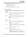
The following file extensions are used by the interface to transfer data:
Extension
Description
.ntr
File with geometry data
.ntrerror
Log file for transfer of geometry
.r2hangprop
File with data for hanger points
.r2hangerror
Log file for hanger points
.r2disp
File for displacement data
Direction
AVEVA DESIGN
PRODUCTS to
Rohr2
Rohr2 to AVEVA
DESIGN PRODUCTS
1.5.1 Type description for AVEVA DESIGN PRODUCTS hanger
Chapter 5.3 gives an overview of all allowed Hanger-Type in the different UDAs.
1.6 Restrictions
The transfer of geometry data is bound to the allowed type declaration of Rohr2. For
example, at the moment it is not possible to transfer tee fittings with three different
bores or reducing elbows. Reducers or elbows with an outlet can also not be
transferred.
Before transferring pipe systems the user should check that the pipes are consistent
concerning geometry or bores. Otherwise problems during the data transfer cannot
be excluded.
Page 4
1.7 Starting AVEVA Pipe Stress Interface - Rohr2
The bidirectional interface is part of the AVEVA DESIGN PRODUCTS Design Piping
Application.
1.7.1 In AVEVA Everything3D™
In Tab PSI-ROHR2 the PSI-R2 commands are grouped in the Piping Application
1.7.2 In AVEVA PDMS
Choose Utilities>Rohr2 Interface in the Piping Application
in order
to get the Rohr2 Interface submenu.
1.7.3 Available commands:
Main
Show the main interface form.
About
Show the version of the AVEVA Pipe Stress Interface - Rohr2.
Page 5
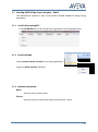
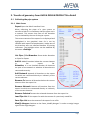
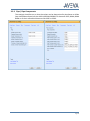
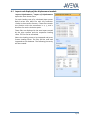
2. The Main Form
Export
Export geometry and
material to Rohr2. Switches back to
the Export frame
Displacement
Switches
to
Displacement frame in order to
create a 3D model for each loading
case defined in Rohr2 result file. This
3D model consists of Nozzles that
show the displacement of the pipe
system. It can be displayed together
with the original pipe system.
Support
Value
Switches to
Support Value. It transfer data of
pipe supports calculated by Rohr2 to
the attributes of the 3D model
elements.
Settings Opens the settings form to
configure the data transfer between
AVEVA DESIGN PRODUCTS and
Rohr2.
Help Opens this documentation.
Page 6
3. Transfer of geometry from AVEVA DESIGN PRODUCTS to Rohr2
3.1 Collecting the pipe system
3.1.1 Main frame
Export Open the Rohr2 Interface Form.
When collecting the pipes of a pipe system to
transfer to Rohr2 it is mandatory that the pipes are in
a network. This means that none of the branches
may be isolated by the rest of the pipe system.
The current content of the export list is displayed and
highlighted in the graphical view. So it can be
checked with respect to completeness, maybe one of
the branches was not collected because of missing
references. The highlight colour can be modified by
the menu >Settings.
List Pipes / List Branches Shows either Branches
or Pipes for Export.
Add Ce Add all branches below the current element
to
the
export
list.
Attention: It is not checked whether all elements
are part of one network or whether all branches are
connected correctly.
Add Network Appends all branches to the export
list which are connected directly or indirectly to the
current element.
Remove Ce Remove all branches below the current
element from the export list.
Remove Network Remove all branches from the
export list which are connected directly or indirectly
to the current element.
Remove Selected Remove the selected elements from the export list.
Load Pipe List Fill the export list with the content of a previously saved file.
Save Pipe List Save the content of the export list to a file.
Modify Hangers Switches to the frame „Modify Hangers“ in order to assign hanger
types to the single hangers.
Page 7
Show Limits Set the limits of the graphical view to the content of the export list.
Show Labels Displays the support of the selected pipes in the graphical view.
Label Types Is only active if “Show Labels” is ticked Show the selected attribute on
the support.
Apply Exports all selected branches. After collecting all geometry and material data
the file browser is opened in order to select the name of the transfer file. The file
extension must be .ntr.
Additionally a second file with the extension .ntrerror is created in the transfer
directory. This log file contains all information about problems or errors during the
export.
Cancel Closes the form
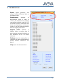
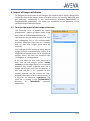
3.1.2 Subframe „Modify Hangers“
The list „Hanger list“ shows all hangers of the
pipe list of the main frame (ATTY unset or ATTY
HANG).
The list “Hanger types” shows all possible hanger
types.
By selecting the hanger points to be modified
and the required hanger types and pressing the
button “Set Hanger type” the respectable
hanger points are modified (Attribute:
USTHTYP).
Clicking the button “Home” switches back to the
main frame.
Page 8
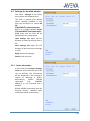
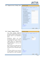
3.2 Settings for the data transfer
The frame Settings of the Rohr2
menu opens the following form.
The form is opened with default
values. Settings modified in that
form can be saved in a central INI
file
(%R2STRESS%\rtwoexportoption.
ini) or in a project specific INI file
(%xyzR2STRESS%\rtwoexportoptio
n.ini). After that the form will be
opened with the saved values.
Load Settings File Open the file
browser to load the settings from a
file
Save Settings File Open the file
browser to save the current settings
in a file
Apply Accept the changes
Cancel Close the form
3.2.1 Order Information
In this frame of the Export Settings
Form any text to describe the order
can be defined. This information
will be displayed in the heading of
reports or drawings in Rohr2.
Alternatively,
AVEVA
DESIGN
commands
(e.g.:
CURRENT
PROJECT) or any standard text is
possible.
AVEVA DESIGN commands must be
entered directly; standard texts
need vertical bars as boundary ‚|’.
Page 9
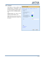
3.2.2 General
This frame is used to define the
environmental temperature and
direction of gravity. Possible values
for the direction of gravity are +X, X, +Y, -Y, +Z, or –Z. Default value is
–Z.
Colours Modify the colours of the
export list (see chapter 3.1.1)
Site Defines the name of the site in
which the displacement model will
be read in.
Page 10
3.2.3 Pipe / Pipe Components
The settings should be set so that the values can be determined by Attributes or UDAs
(user defined attributes) of the AVEVA DESIGN PRODUCTS elements PIPE, BRAN, BRAN
MEM or of their referenced elements like SPEC or SPCO.
Page 11
3.2.4 Expansion Joints, Tab Exp. Joints
3.2.5 Hanger + Supports, Tab HS
The AVEVA DESIGN PRODUCTS
elements ATTA/SHU/MDS (-Atta) can
be used for hanger or support points.
Default value is the Attachment
point.
Attachment
points
are
only
transferred to Rohr2, if the value of
the attribute ATT type is set to
„HANG“, „NULL“ or „“ (empty/unset)
and additionally the value of the
attribute FStatus is not set to
„INSULATION“.
Both elements are provided with the
UDAs: USTHTYP (hanger type) and:
USTSCHTYP (stress calculated hanger
type).
The UDA: USTHTYP can be used by
the pipe designer to define a hanger
type before the stress calculation.
Page 12
The selection is limited by the hanger types of the company Witzenmann.
The UDA: USTSCHTYP is set by Rohr2 and contains the hanger type after the stress
calculation by Rohr2. If there is an equivalent hanger type of the company
Witzenmann, the UDA: USTHTYP will be overwritten during the import process of the
Rohr2 data.
When transferring geometry to Rohr2 the UDA: USTSCHTYP is checked for a hanger
type that had already been transferred from Rohr2. In that case it would be
transferred to Rohr2 again. If the UDA does not contain a valid value, then the UDA:
USTHTYP is analysed and transferred if necessary. If this UDA also does not contain a
valid value then the standard hanger type from the Settings Form will be used.
The advantage of that procedure is that the pipe designer does not have to define any
hanger types in the AVEVA DESIGN PRODUCTS. The stress calculator gets the chance
to define a default hanger type for the first stress calculation in Rohr2. For example, it
is possible to define a constant hanger for steam pipes or a friction-type bearing for
water pipes as a default. The following alternatives can be selected in the Settings
Form:
Constant hanger <Standard>
Rigid hanger
Friction-type bearing
Spring hanger
3.2.6 Userfunctions
To be more flexible, complex structure can be implemented in the R2 interface
ATTA Name !!attaname() und PCOM Classification !!pcomClasses() are shown in the
settings form.
Both are provided as an example and placed in the PMLLIB path below userfunction.
Please see here !!attaname() as an example:
--------------------------------------------------------------------define function !!attaName() is string
if !!ce.type.eq('ATTA')
then
return !!ce.stext & '-' & !!ce.:mdssuppfunc
else
return !!ce.name
endif
endfunction
---------------------------------------------------------------------
Page 13
4. Displaying the thermal displacements
One result of the stress calculation in Rohr2 is the displacements based on thermal
influences on the whole pipe system. These displacements can be displayed in the
AVEVA DESIGN PRODUCTS.
For each loading case a separate model containing equipment elements with nozzles
are created. These models can be displayed together with the original pipe.
In order to read in the displacement files a design database with write access must be
selected. In this database a site (in the example /R2) must be created. The attribute
PURPOSE of that site must get the value DISP.
If there is such a site in a read/write database it will be displayed in the form.
It must be taken into account, that the imported models of the loading cases will
cause hard clashes inside the AVEVA DESIGN PRODUCTS. Therefore it is recommended
to import the model in database that is not always current, only temporarily to check
the loading cases.
As mentioned above, the loading case models are based on parameterised NOZZles (in
the shape of a dumb-bell). The nozzles represent two adjacent calculation points and
the direct line between these two points with two spheres and one cylinder. The
“pipe” can also be shown with the insulation. In order to display the insulation the
transparency of Obstruction and Insulation should be set to 50% in the graphical
representation form (>Settings>Representation) in the main menu of AVEVA DESIGN
PRODUCTS.
Page 14
4.1 Import and display of the displacement models
Import Displacement / Import of Displacement
opens the form shown here.
For each loading case of a calculated pipe system
Rohr2 writes one ASCII file with the extension
.r2disp in the transfer directory. These files contain
the position with the movement in x, y, and z
direction for each calculation point.
These files are displayed in the area Import sorted
by the pipe systems and the respective loading
cases. The list can be refreshed.
Select the loading cases to be imported and press
Create Loading Cases. The files will be read and
imported to the database. The following hierarchy
will be created:
Page 15
Type
Name
Beschreibung
SITE
/DISP
ZONE
/DISP_28MAW30
This ZONE contains all loading
cases of the system 28MAW30
EQUI
/DISP_28MAW30_DL
This EQUI contains the loading
case DL
SUBE
…/F0HAC10BR011/B1
The SUBEquipment contains
the branch /F0HAC10BR011/B1
of the loading case DL.
NOZZ
…/F0HAC10BR011/B1_260-280
The NOZZle represents the
connection between the
calculation points 260 and 280.
After importing the loading cases the Import area of the form will be updated and the
area Graphical Representations will be filled with the content of the database.
During the import the imported files will be renamed from .r2disp to .r2dispold.
The imported loading cases are shown per pipe system. For each pipe system the
single loading cases and all branches of that system are listed. The display of the
loading cases can be switched on and off and can superimposed with the original
branch (Showing Branch). The colours can be adjusted individually.
Only branches selected in the branch list (Branches) are shown in the graphical view.
Selecting the System again will update the graphical view with all branches of the
system.
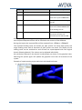
Example of superimposing a pipe with their calculated load cases
the original pipe in blue
Page 16
the model of the loading case OPLOAD1 in red
the original pipe model in blue superimposed with the loading case OPLOAD1 in red
4.2 Error messages during the import of displacement files
If the UST-UDAs are not available, a message will be shown to contact the system
administrator. Without the UDAs the interface will not work.
The error can be caused by:
The respective DICT database was not created in the module ADMIN.
The respective DICT database was not included in the current MDB or is deferred.
The required UDAs are not included in the DICT database. Please see chapter 1.4.1. for
details
The DICT database was not compiled.
Page 17
5. Import of hanger attributes
For design and construction of pipe hangers and supports Rohr2 delivers design data.
The design data for the hanger points of all pipe systems are stored in ASCII files with
the extension .r2hangprop in the communication directory %R2STRESS% or
%xyzR2STRESS% respectively. The values are transferred to the attributes of the
corresponding ATTAchment Points.
5.1 Form for the import of the hanger point data
The following form is opened by Import
Displacement / Import of Support Value of the
main menu of AVEVA DESIGN PRODUCTS.
The form will only be shown if there is at least
one .r2hangprop file in the communication
directory. Otherwise there will be a warning
that no files with hanger point data are
available.
The .r2hangprop files contain all design data of
hanger points of a calculated pipe system. If all
design data of hanger points can be transferred
without errors, the files are renamed from
.r2hangprop to .r2hangpropold.
If the user does not have write access to at
least one of the hanger points (locked,
claimed) or if the hanger point is in a read-only
database, then a form is opened with a list of
hanger points that could not be updated. In
this case the file is not renamed so that
another attempt can be carried out later.
Detailed information of errors will be written in
a file with the extension .r2hangerror. The
error file is created in the %xyzR2STRESS%
directory
or
%R2STRESS%
directory,
respectively.
Page 18
5.2 Definition of the transferred data
The following attributes of ATTAment points are set:
UDA name
Example
Description
:USTDYNLOAD
1.8 2.6 3.8
Dynamic load in x, y, z direction
[kN]
:USTEREPORT
|Rep No 124711|
Elasticity report [text: max. 120
characters]
:USTFORCE
10 5.6 7.8
Forces in x, y, z direction [kN]
:USTHCOMP
|507845|
Part number of the spring or
constant hanger
:USTMAXTRAVEL
3.6
Max. Movement [mm]
:USTMOVEMENT
2.1 3.5 0.7 3.4 4.3
1. value: Movement in
x direction [mm]
2. value: Movement in
y direction [mm]
3. value: Movement in
z direction [mm]
4. value: positive dynamic
movement [mm]
5. value: negative dynamic
movement [mm]
:USTNODENUMB
1023
Node number of the hanger point
:USTSRATE
4.5
Spring rate [N/mm]
:USTSTATLOAD
7.8
Static load [kN]
:USTTESTLOAD
4.3
Water test load [kN]
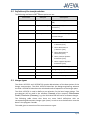
5.3 Hanger types
The UDAs: USTHTYP and: USTSCHTYP contain abbreviations of the descriptions of the
hanger constructions. The UDA: USTHTYP describes the design-engineering whereas
the UDA: USTSCHTYP describes the calculated mode of operation at the hanger point.
The UDA: USTHTYP is used to define a pre-selection for the later hanger design. This
pre-selection will be used in the software Cascade of the company Witzenmann
GmbH, Pforzheim (Germany), e.g. the UDA value KH will lead to a constant hanger.
The following table shows that there are some Rohr2 definitions with no
corresponding Witzenmann hanger type (none). In such a case the definition must be
done in the program Cascade.
This table gives an overview of the most common types.
Page 19
Description
Witzenmann
Rohr2
UDA:
:USTHTYP
:USTSCHTYP
General clamp
AC
none
Rigid support
GS
GS
Rigid hanger
SH
SH
Spring hanger
FH
FH
Constant hanger
KH
KH
General rigid support
GS
ST
Fix point
FP
FP
Friction bearing vertical
None
GL
Lateral thrust bearing vertical
None
FL
Axial stop
None
AX
Lateral stop horizontal
None
QS
Stauff-clamp
SC
none
Friction bearing + Axial stop vertical, axial
None
GLAX
Thrust bearing + Axial stop all movements
None
FLAX
Lateral stop + Axial stop horizontal lateral,
axial
None
QSAX
Thrust bearing vertical, guiding in the global
x axis
None
FLVX
Thrust bearing vertical, guiding in the global
y axis
None
FLVY
Thrust bearing vertical, guiding in the global
z axis
None
FLVZ
Thrust bearing vertical, guiding in the global
x and y axis
None
FLVXY
Thrust bearing vertical, guiding in the global
x and z axis
None
FLVXZ
Thrust bearing vertical, guiding in the global
y and z axis
None
FLVYZ
Lateral stop in vertical pipe
None
QSV
Lateral stop in vertical pipe in the global x
axis
None
QSVX
Page 20
Description
Witzenmann
Rohr2
UDA:
:USTHTYP
:USTSCHTYP
Lateral stop in vertical pipe in the global y
axis
None
QSVY
Lateral stop in vertical pipe in the global z
axis
None
QSVZ
General Spring support
None
FS
Spring support
FS
FGL
Spring support + guidance
None
FFL
Spring support + axial stop
FS
FGLAX
Spring support + guidance + axial stop
FS
FFLAX
Spring support + guidance in vertical and
global x direction
FS
FFLVX
Spring support + guidance in vertical and
global y direction
FS
FFLVY
Spring support + guidance in vertical and
global z direction
FS
FFLVZ
Spring support + guidance in vertical and
global x and y direction
FS
FFLVXY
Spring support + guidance in vertical and
global x and z direction
FS
FFLVXZ
Spring support + guidance in vertical and
global y and z direction
FS
FFLVYZ
Constant support
KS
KGL
Constant support + guidance
KS
KFL
Constant support + axial stop
KS
KGLAX
Constant support + guidance + axial stop
KS
KFLAX
Constant support + guidance in vertical and
global x direction
KS
KFLVX
Constant support + guidance in vertical and
global y direction
KS
KFLVY
Constant support + guidance in vertical and
global z direction
KS
KFLVZ
Constant support + guidance in vertical and
global x and y direction
KS
KFLVXY
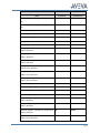
Page 21
Description
Witzenmann
Rohr2
UDA:
:USTHTYP
:USTSCHTYP
Constant support + guidance in vertical and
global x and z direction
KS
KFLVXZ
Constant support + guidance in vertical and
global y and z direction
KS
KFLVYZ
General pivot support
GS
GS
Rigid pivot support vertical
GS
GSV
Rigid pivot support lateral
GS
GSQ
Rigid pivot support axial
GS
GSAX
Rigid pivot support in vertical pipe lateral in
global x direction
GS
GSQVX
Rigid pivot support in vertical pipe lateral in
global y direction
GS
GSQVY
Rigid pivot support in vertical pipe lateral in
global z direction
GS
GSQVZ
Elastic pivot support vertical
FS
FGSV
Elastic pivot support lateral
FS
FGSQ
Elastic pivot support axial
FS
FGSAX
Elastic pivot support in vertical pipe lateral
in global x direction
FS
FGSQVX
Elastic pivot support in vertical pipe lateral
in global y direction
FS
FGSQVY
Elastic pivot support in vertical pipe lateral
in global z direction
FS
FGSQVZ
Constant pivot support vertical
KS
KGSV
Constant pivot support lateral
KS
KGSQ
Constant pivot support axial
KS
KGSAX
Constant pivot support in vertical pipe
lateral in global x direction
KS
KGSQVX
Constant pivot support in vertical pipe
lateral in global y direction
KS
KGSQVY
Constant pivot support in vertical pipe
lateral in global z direction
KS
KGSQVZ
*none means „undefined“
Page 22
The 3D designer can choose a particular hanger construction for the calculation in
Rohr2.
5.3.1 Transfer from AVEVA DESIGN PRODUCTS to Rohr2
If a hanger was calculated with Rohr2 the UDA: USTSCHTYP contains this calculated
data. If the hanger point is transferred to Rohr2 again this data will be used.
If this UDA is empty or contains invalid data the UDA :USTHTYP will be transferred to
Rohr2 if it is valid.
If both UDAs contain invalid data the default standard hanger type will be transferred.
5.3.2 Transfer from Rohr2 to AVEVA DESIGN PRODUCTS
During the transfer procedure of the Rohr2 data the calculated hanger type is written
to the UDA: USTSCHTYP. Additionally, the Witzenmann hanger type is determined and
written to the UDA: USTHTYP.
5.4 Error messages
If the UST-UDAs are not available, a message will be shown to contact the system
administrator. Without the UDAs the interface will not work.
The error can be caused by:
The respective DICT database was not created in the module ADMIN.
The respective DICT database was not included in the current MDB or is deferred.
The required UDAs are not included in the DICT database. Please see Chapter 1.4.1. for
details
The DICT database was not compiled.
As mentioned above, it is possible that user do not have write access to some ATTA
elements due to claims or locks or due to general read-only access.
In addition to the error messages all ATTA or SHU elements that could not be
transferred are listed in an error form. The reasons for the single errors are listed in an
.r2hangerror file.
Page 23
Page 24
AVEVA Solutions Limited
High Cross
Madingley Road
Cambridge, CB3 0HB
UK
Tel +44 (0)1223 556655
Fax +44 (0)1223 556666
www.aveva.com
Copyright © 2013 AVEVA Solutions Limited. All rights reserved. AVEVA Solutions Limited is owned by AVEVA Group plc. AVEVA, the AVEVA logos and AVEVA product names are
trademarks or registered trademarks of AVEVA Group plc or its subsidiaries in the United Kingdom and other countries. Other brands and products names are the trademarks of their
respective companies.
Page 25