1
AVEVA Plant suite
Version 12.1
User Bulletin
Disclaimer
1.1 AVEVA does not warrant that the use of the AVEVA software will be uninterrupted, error-free or free from viruses.
1.2 AVEVA shall not be liable for: loss of profits; loss of business; depletion of goodwill and/or similar losses; loss of
anticipated savings; loss of goods; loss of contract; loss of use; loss or corruption of data or information; any special,
indirect, consequential or pure economic loss, costs, damages, charges or expenses which may be suffered by the user,
including any loss suffered by the user resulting from the inaccuracy or invalidity of any data created by the AVEVA
software, irrespective of whether such losses are suffered directly or indirectly, or arise in contract, tort (including
negligence) or otherwise.
1.3 AVEVA shall have no liability in contract, tort (including negligence), or otherwise, arising in connection with the
performance of the AVEVA software where the faulty performance of the AVEVA software results from a user's
modification of the AVEVA software. User's rights to modify the AVEVA software are strictly limited to those set out in the
Customisation Manual.
1.4 AVEVA shall not be liable for any breach or infringement of a third party's intellectual property rights where such
breach results from a user's modification of the AVEVA software or associated documentation.
1.5 AVEVA's total liability in contract, tort (including negligence), or otherwise, arising in connection with the performance
of the AVEVA software shall be limited to 100% of the licence fees paid in the year in which the user's claim is brought.
1.6 Clauses 1.1 to 1.5 shall apply to the fullest extent permissible at law.
1.7. In the event of any conflict between the above clauses and the analogous clauses in the software licence under which
the AVEVA software was purchased, the clauses in the software licence shall take precedence.
Copyright
Copyright and all other intellectual property rights in this manual and the associated software, and every part of it
(including source code, object code, any data contained in it, the manual and any other documentation supplied with it)
belongs to, or is validly licensed by, AVEVA Solutions Limited or its subsidiaries.
All rights are reserved to AVEVA Solutions Limited and its subsidiaries. The information contained in this document is
commercially sensitive, and shall not be copied, reproduced, stored in a retrieval system, or transmitted without the prior
written permission of AVEVA Solutions Limited. Where such permission is granted, it expressly requires that this copyright
notice, and the above disclaimer, is prominently displayed at the beginning of every copy that is made.
The manual and associated documentation may not be adapted, reproduced, or copied, in any material or electronic form,
without the prior written permission of AVEVA Solutions Limited. Subject to the user's rights, as set out in the
customisation manuals to amend PML software files contained in the PDMSUI and PDMSLIB folders and any
configuration files, the user may not reverse engineer, decompile, copy, or adapt the software. Neither the whole, nor part
of the software described in this publication may be incorporated into any third-party software, product, machine, or
system without the prior written permission of AVEVA Solutions Limited, save as permitted by law. Any such unauthorised
action is strictly prohibited, and may give rise to civil liabilities and criminal prosecution.
The AVEVA software described in this guide is to be installed and operated strictly in accordance with the terms and
conditions of the respective software licences, and in accordance with the relevant User Documentation. Unauthorised or
unlicensed use of the software is strictly prohibited.
Copyright 1974 to current year. AVEVA Solutions Limited and its subsidiaries. All rights reserved. AVEVA shall not be
liable for any breach or infringement of a third party's intellectual property rights where such breach results from a user's
modification of the AVEVA software or associated documentation.
AVEVA Solutions Limited, High Cross, Madingley Road, Cambridge, CB3 0HB, United Kingdom.
Trademark
AVEVA and Tribon are registered trademarks of AVEVA Solutions Limited or its subsidiaries. Unauthorised use of the
AVEVA or Tribon trademarks is strictly forbidden.
AVEVA product/software names are trademarks or registered trademarks of AVEVA Solutions Limited or its subsidiaries,
registered in the UK, Europe and other countries (worldwide).
rd
3 Party Software
The copyright, trademark rights, or other intellectual property rights in any other product or software, its name or logo belongs to its
respective owner.
The following 3rd party software is included in some of the AVEVA products described in this document:
Teigha™ for .dgn files 2007-2010 by Open Design Alliance. All rights reserved.
Teigha™ for .dwg files 2003-2010 by Open Design Alliance. All rights reserved.
Microsoft® Office Fluent™ user interface. Fluent is a trademark of Microsoft Corporation and the Fluent user interface is
licensed from Microsoft Corporation. The Microsoft Office User Interface is subject to protection under U.S. and international
intellectual property laws and is used by AVEVA Solutions Limited under license from Microsoft.
AVEVA Plant 12.1 User Bulletin
Contents
1
INTRODUCTION ...................................................................................................1-1
1.1
1.2
1.3
1.3.1
1.3.2
1.3.3
1.3.4
1.3.5
1.4
1.4.1
1.4.2
1.4.3
1.4.4
1.5
ABOUT THIS SOFTWARE RELEASE ............................................................................................. 1-1
ABOUT THIS MANUAL................................................................................................................ 1-1
SOFTWARE DISTRIBUTION AND INSTALLATION ............................................................................ 1-1
Products installed by the main AVEVA Plant (PDMS) installer ............................................ 1-1
Products installed by separate installers............................................................................... 1-2
Overview of installation process ........................................................................................... 1-2
Installation in folders with embedded spaces ....................................................................... 1-3
Projects in folders with embedded spaces............................................................................ 1-4
AVEVA PLANT PORTFOLIO ...................................................................................................... 1-5
AVEVA Plant Version 12.1 .................................................................................................... 1-5
AVEVA Plant Engineer Products .......................................................................................... 1-5
AVEVA Plant Design Products ............................................................................................. 1-6
AVEVA Plant Manage Products ............................................................................................ 1-7
AVEVA PLANT VERSION 12.1.1 ............................................................................................... 1-7
2
AVEVA PLANT PORTFOLIO UPDATES AT 12.1 ................................................2-9
2.1
2.1.1
2.1.2
2.1.3
2.1.4
2.1.5
2.2
2.2.1
2.2.2
2.3
2.3.1
2.3.2
2.4
2.4.1
2.4.2
2.5
2.6
2.7
2.7.1
2.7.2
2.7.3
2.7.4
2.7.5
2.7.6
2.7.7
2.8
2.8.1
2.8.2
2.8.3
2.8.4
2.8.5
2.8.6
2.8.7
2.8.8
GENERAL ................................................................................................................................ 2-9
Improved local language – Unicode encoding ...................................................................... 2-9
Units of measure – extended range of conversions ............................................................. 2-9
Performance .......................................................................................................................... 2-9
Database accuracy ............................................................................................................... 2-9
Application update and consistency .................................................................................... 2-10
PDMS 12.1 .......................................................................................................................... 2-10
Design ................................................................................................................................. 2-10
Drawing Production ............................................................................................................. 2-10
OTHER PLANT DESIGN PRODUCTS ......................................................................................... 2-10
Multi-Discipline Supports (MDS) ......................................................................................... 2-10
Global .................................................................................................................................. 2-10
PLANT ENGINEER PRODUCTS................................................................................................. 2-10
Engineering ......................................................................................................................... 2-10
Schematics .......................................................................................................................... 2-11
SAMPLE MODEL DATA ............................................................................................................ 2-11
DOCUMENTATION .................................................................................................................. 2-11
OPERATING ENVIRONMENT..................................................................................................... 2-12
PC hardware configuration ................................................................................................. 2-12
Microsoft Windows .............................................................................................................. 2-12
Microsoft Internet Explorer .................................................................................................. 2-12
Microsoft .NET Framework ................................................................................................. 2-12
Microsoft Office & fonts ....................................................................................................... 2-13
Graphics cards .................................................................................................................... 2-13
Environment variables......................................................................................................... 2-14
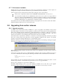
UPGRADING FROM EARLIER RELEASES .................................................................................... 2-14
Upgrade overview ............................................................................................................... 2-14
DBUpgrade command......................................................................................................... 2-15
Database Version Control ................................................................................................... 2-15
Global .................................................................................................................................. 2-15
The Upgrade Process ......................................................................................................... 2-15
Locking the Project .............................................................................................................. 2-16
Extract Hierarchies .............................................................................................................. 2-16
International characters (Unicode) ...................................................................................... 2-17
Copyright 1974 to current year. AVEVA Solutions Ltd.
i
12.1.1
2.8.9
2.8.10
2.9
2.9.1
2.9.2
2.9.3
2.10
2.11
2.11.1
2.11.2
2.11.3
Units of measure ................................................................................................................. 2-17
Schematics functions .......................................................................................................... 2-18
COMPATIBILITY ...................................................................................................................... 2-18
AutoCAD ............................................................................................................................. 2-18
Final Designer ..................................................................................................................... 2-18
Data Access Routines (DARs) ............................................................................................ 2-18
NOTICE OF CHANGE IN SUPPORT STATUS ................................................................................ 2-18
FUTURE CONSIDERATIONS ..................................................................................................... 2-18
Access platforms, Stairs and Ladders (ASL) ...................................................................... 2-18
Hangers & Supports (H&S) ................................................................................................. 2-19
PDMS Plotfiles .................................................................................................................... 2-19
3
DATABASE CHANGES ......................................................................................3-21
3.1
3.1.1
3.1.2
3.2
3.3
3.3.1
3.4
3.5
3.5.1
3.5.2
3.5.3
3.5.4
3.6
3.7
3.7.1
3.7.2
3.8
3.9
3.10
3.11
NEW DATABASE TYPES .......................................................................................................... 3-21
Engineering Database......................................................................................................... 3-21
Design Reference database ............................................................................................... 3-21
ACCESS TO DATABASES ......................................................................................................... 3-22
INCREASE IN NUMBER OF DATABASES ..................................................................................... 3-23
Admin GUI ........................................................................................................................... 3-23
DUPLICATE NAMES ................................................................................................................ 3-23
FLEXIBILITY OF DATA ORGANISATION....................................................................................... 3-24
Database views ................................................................................................................... 3-24
Distributed attributes ........................................................................................................... 3-24
Handling of duplicated names of UDAs and UDETs .......................................................... 3-24
Top-level element creation in specific database ................................................................. 3-24
DYNAMIC GROUPS................................................................................................................. 3-25
DATABASE PERFORMANCE ..................................................................................................... 3-25
Dabacon buffer .................................................................................................................... 3-25
Dabacon index tables.......................................................................................................... 3-26
UNITS OF MEASURE ............................................................................................................... 3-26
UNICODE STORAGE OF NAME AND TEXT ATTRIBUTES................................................................ 3-26
DRAFT LINE-STYLE WORLD HIERARCHY ................................................................................. 3-26
EXTRACT CONTROL – INCLUDE FLUSH CAPABILITY .................................................................. 3-26
4
GENERAL SYSTEM CHANGES .........................................................................4-29
4.1
4.1.1
4.1.2
4.1.3
4.1.4
4.1.5
4.1.6
4.1.7
4.2
4.2.1
4.2.2
4.2.3
4.3
4.4
4.5
4.6
4.6.1
4.6.2
4.7
UNICODE CHARACTER HANDLING ............................................................................................ 4-29
Restrictions ......................................................................................................................... 4-29
Textual File handling ........................................................................................................... 4-29
Filenames and PML ............................................................................................................ 4-29
Using Forms and Menus ..................................................................................................... 4-30
Using TTY mode ................................................................................................................. 4-30
PDMS Databases ................................................................................................................ 4-30
Graphical output .................................................................................................................. 4-31
UNITS OF MEASURE ............................................................................................................... 4-32
Supported Dimensions and Units ....................................................................................... 4-32
Other UNITS commands ..................................................................................................... 4-34
Upgrading to use new units ................................................................................................ 4-35
ENHANCED PASSWORD PROTECTION ...................................................................................... 4-36
STATUS CONTROL ................................................................................................................. 4-36
TAG COMPARE / UPDATE ....................................................................................................... 4-37
REPORT GENERATION ............................................................................................................ 4-37
New Reporting add-in ......................................................................................................... 4-37
‘Classic’ Reporting .............................................................................................................. 4-38
GML PERFORMANCE ............................................................................................................. 4-38
5
USER INTERFACE .............................................................................................5-39
5.1
5.2
5.2.1
5.2.2
5.2.3
ENTRY TO SYSTEM................................................................................................................. 5-39
UNITS OF MEASURE............................................................................................................... 5-39
Current Session Units ......................................................................................................... 5-39
Project Default units ............................................................................................................ 5-40
Dataset Properties .............................................................................................................. 5-41
Copyright 1974 to current year. AVEVA Solutions Ltd.
ii
12.1.1
5.2.4
5.3
5.4
5.5
5.6
5.7
5.8
5.8.1
5.8.2
5.8.3
5.9
5.9.1
5.9.2
5.10
Decimal Separator .............................................................................................................. 5-41
W ORLD AXES ON 3D VIEWS.................................................................................................... 5-41
SAVE AND RESTORE VIEWS .................................................................................................... 5-41
GRID CONTROL ..................................................................................................................... 5-42
TOOLBAR POPUP MENU .......................................................................................................... 5-42
SUPPORT FOR RIBBON STYLE GUI ......................................................................................... 5-42
APPLICATION UPDATE AND CONSISTENCY ............................................................................... 5-42
PML Collections .................................................................................................................. 5-42
Attribute display, editing and validation............................................................................... 5-42
Auto-naming utility enhancement ........................................................................................ 5-43
ADDITIONAL DEBUG INFORMATION ABOUT PML APPLICATIONS ................................................. 5-44
Help about ........................................................................................................................... 5-44
PML alert ............................................................................................................................. 5-45
INFRAGISTICS TOOLKIT ........................................................................................................... 5-45
6
ADMINISTRATION..............................................................................................6-47
6.1
6.2
6.3
6.3.1
6.4
6.4.1
6.4.2
6.4.3
6.4.4
6.5
6.5.1
6.5.2
6.5.3
6.5.4
6.5.5
6.5.6
ENGINEERING (ENGI) DATABASE ........................................................................................... 6-47
TAGS MODULE DEFINITION .................................................................................................... 6-47
GUI IMPROVEMENTS.............................................................................................................. 6-47
Import from Excel ................................................................................................................ 6-47
LEXICON ............................................................................................................................... 6-47
New Lexicon graphical view ................................................................................................ 6-47
UDA lists of values .............................................................................................................. 6-48
Database Views .................................................................................................................. 6-48
General................................................................................................................................ 6-49
ADMIN GUI CHANGES FOR GLOBAL ........................................................................................ 6-49
Global support for Linked documents ................................................................................. 6-49
Database distribution form .................................................................................................. 6-51
Creation of an event without times ...................................................................................... 6-52
Remote file details in Admin ............................................................................................... 6-52
Satellite Commands filter for Transactions ......................................................................... 6-52
Enhanced User Interface for Sessions ............................................................................... 6-52
7
GLOBAL .............................................................................................................7-55
7.1
7.2
7.3
7.4
7.5
GLOBAL CLAIM COMMANDS..................................................................................................... 7-55
GLOBAL WCF ....................................................................................................................... 7-55
GLOBAL WCF SERVICE NAME ................................................................................................ 7-55
ADUUID ATTRIBUTE LENGTH................................................................................................. 7-56
GLOBAL TRANSFER OF LINKED DOCUMENTS ........................................................................... 7-56
8
CATALOGUE & SPECIFICATIONS ....................................................................8-59
8.1
8.2
8.3
8.4
MODEL SETTINGS .................................................................................................................. 8-59
PARAMETERISED DETAIL TEXT ................................................................................................ 8-59
COPY BUTTON FOR STRUCTURAL CATALOGUE ......................................................................... 8-59
CREATION OF STRUCTURAL SPECS ........................................................................................ 8-60
9
PDMS DESIGN ...................................................................................................9-61
9.1
9.1.1
9.1.2
9.2
9.2.1
9.3
9.3.1
9.3.2
9.3.3
9.3.4
9.4
9.5
9.6
9.7
MODEL EDITOR ..................................................................................................................... 9-61
Offset From Feature… option ............................................................................................. 9-61
Structural primitives ............................................................................................................. 9-61
MOVE, DRAG MOVE AND PLANE MOVE COMMANDS ................................................................ 9-62
Summary of Move, Drag Move and Plane Move options ................................................... 9-62
CHANGE HIGHLIGHTING AND REVERSION ................................................................................. 9-63
Enhanced User Interface for Sessions ............................................................................... 9-63
Revert Elements Command ................................................................................................ 9-63
Change Highlighting via Extract Data Control .................................................................... 9-64
Change Highlighting via Model Changes Add-in ................................................................ 9-65
ENHANCED ATTRIBUTE EXPORT TO REVIEW ............................................................................ 9-69
W EIGHT AND CENTRE OF GRAVITY (COFG) FORM ................................................................... 9-70
DRAFT EXPLORER ............................................................................................................... 9-70
AVEVA MECHANICAL EQUIPMENT INTERFACE ........................................................................ 9-70
Copyright 1974 to current year. AVEVA Solutions Ltd.
iii
12.1.1
10
PDMS DESIGN APPLICATIONS ...................................................................... 10-71
10.1
10.2
10.2.1
10.2.2
10.2.3
10.2.4
10.2.5
10.3
10.3.1
10.4
10.4.1
10.4.2
10.4.3
10.4.4
10.4.5
10.4.6
10.4.7
10.5
10.5.1
10.6
10.7
10.7.1
10.8
10.8.1
10.8.2
10.9
10.10
10.10.1
10.10.2
10.10.3
EQUIPMENT ......................................................................................................................... 10-71
PIPING ................................................................................................................................ 10-71
Sloping piping .................................................................................................................... 10-71
Direct setting of Insulation Thickness & Material .............................................................. 10-72
Bending Machine NC Output ............................................................................................ 10-72
Improved production checks ............................................................................................. 10-72
Material search for Pipe Bending Machine setup ............................................................. 10-72
STRUCTURES ...................................................................................................................... 10-73
Steelwork Connectivity Upgrade ....................................................................................... 10-73
HOLE MANAGEMENT ENHANCEMENTS................................................................................... 10-73
Create Holes ..................................................................................................................... 10-73
Merge Holes ...................................................................................................................... 10-73
Modify (and Delete) Holes................................................................................................. 10-74
Utilities ............................................................................................................................... 10-74
Managed hole reports ....................................................................................................... 10-74
Configuration of Hole Management Data.......................................................................... 10-76
Hole Association Manager ................................................................................................ 10-76
PENETRATION WITH PIPING COMPONENT .............................................................................. 10-78
Creation of Penetration ..................................................................................................... 10-78
STANDARD MODEL LIBRARY................................................................................................. 10-79
CLASH UTILITY ENHANCEMENTS ........................................................................................... 10-80
Reports .............................................................................................................................. 10-85
AVEVA NUCLEAR APPLICATIONS ......................................................................................... 10-86
Units .................................................................................................................................. 10-86
List of Connected elements .............................................................................................. 10-86
AVEVA CABLE DESIGN ....................................................................................................... 10-87
AVEVA MULTI-DISCIPLINE SUPPORTS ................................................................................. 10-87
Cable Tray Supports ......................................................................................................... 10-87
Automatic generation of pads ........................................................................................... 10-88
Updating client project defaults ......................................................................................... 10-88
11
PDMS DRAWING PRODUCTION ..................................................................... 11-89
11.1
11.2
11.3
11.3.1
11.3.2
11.3.3
11.3.4
11.4
11.5
11.6
11.7
11.8
11.9
11.9.1
11.9.2
11.9.3
11.9.4
11.10
EXTENDED HATCH PATTERNS ............................................................................................... 11-89
LINE STYLES........................................................................................................................ 11-89
LINE WIDTHS ....................................................................................................................... 11-89
System defined line styles................................................................................................. 11-89
User defined line styles ..................................................................................................... 11-90
Minimum Line Width.......................................................................................................... 11-90
Plotting user interface ....................................................................................................... 11-90
ENHANCED ANGULAR DIMENSIONS....................................................................................... 11-91
ENHANCED P-LINE PICKING.................................................................................................. 11-91
IMPROVED PERFORMANCE OF EXTRUSIONS ........................................................................... 11-91
DRAWING GRIDLINES ........................................................................................................... 11-92
INTELLIGENT TEXT HANDLING ENHANCEMENT ........................................................................ 11-92
EXPORT TO CAD FORMATS .................................................................................................. 11-92
Support for Unicode text ................................................................................................... 11-92
Improved drawing feature export ...................................................................................... 11-92
Configurable DXF & DWG export ..................................................................................... 11-93
Configurable DGN export .................................................................................................. 11-93
AVEVA ISOMETRIC ADP ..................................................................................................... 11-93
12
PDMS PIPING ISOMETRICS ............................................................................ 12-95
12.1
12.2
12.3
12.4
12.4.1
12.4.2
12.4.3
NEW OUTPUT FILE FORMATS, INCLUDING PDF ....................................................................... 12-95
TRUETYPE FONTS ............................................................................................................... 12-95
LARGE COORDINATES.......................................................................................................... 12-96
ADDITIONAL COORDINATE FORMATS .................................................................................... 12-96
COFORMAT ...................................................................................................................... 12-96
COUNITS .......................................................................................................................... 12-96
CODECP ........................................................................................................................... 12-96
Copyright 1974 to current year. AVEVA Solutions Ltd.
iv
12.1.1
12.4.4
12.5
12.6
12.7
12.8
COIMPP ............................................................................................................................ 12-96
DRAWING PIPE SPOOL (PSPOOL) ELEMENTS ....................................................................... 12-96
‘NORTH’ ARROW TEXT ......................................................................................................... 12-97
PIPE PENETRATION SEAL SYMBOL ....................................................................................... 12-97
SETTING UNITS IN OPTIONS FILES ........................................................................................ 12-97
13
AVEVA SCHEMATIC 3D INTEGRATOR .......................................................... 13-99
13.1
13.2
13.3
13.4
13.5
13.6
13.7
NEW INTEGRATOR OBJECT METHOD .................................................................................... 13-99
ELECTRICAL CONNECTIONS .................................................................................................. 13-99
W HOLE DIAGRAM COMPARE ................................................................................................ 13-99
SELECTOR RULES ............................................................................................................... 13-99
IMPROVED LINKS ADMINISTRATION ..................................................................................... 13-100
CONFIGURATION RULES EXTENSIONS................................................................................. 13-100
EXAMPLE MACRO .............................................................................................................. 13-101
14
AVEVA DIAGRAMS ........................................................................................ 14-103
14.1
14.2
14.3
14.4
14.5
14.6
14.7
14.8
14.9
14.10
14.10.1
14.11
14.12
14.13
14.14
14.15
14.15.1
14.15.2
14.16
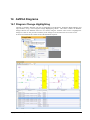
DIAGRAM CHANGE HIGHLIGHTING ...................................................................................... 14-103
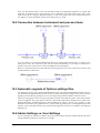
CONNECTION BETWEEN INSTRUMENT AND PROCESS ITEMS .................................................. 14-104
AUTOMATIC UPGRADE OF OPTIONS SETTINGS FILES ............................................................ 14-104
ADMIN SETTINGS VS. USER SETTINGS ................................................................................ 14-104
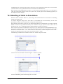
HANDLING OF UNITS IN ANNOTATIONS ................................................................................ 14-105
AVEVA NET GATEWAY .................................................................................................... 14-106
AUTOMATIC LINE BREAKS DEPENDING ON LINE PRIORITY. ................................................... 14-106
IMPROVED SHAPE ANNOTATION IN SCHEMATIC MODEL VIEWER ........................................... 14-106
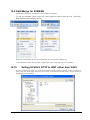
SPLIT-MERGE FOR SCBRAN............................................................................................. 14-107
SETTING SCVALV GTYP TO INST RATHER THAN VALV .................................................... 14-107
Changing existing items .................................................................................................. 14-108
CHANGES TO UPGRADE DRAWING FUNCTION ..................................................................... 14-109
LINKED FILES UPDATE ....................................................................................................... 14-110
DETERMINE CONNECTOR RE-ROUTE STYLE........................................................................ 14-110
SETTING DEFAULT VALUE OF STENCIL IN BATCH ................................................................. 14-111
AUTO HIDE OPTION FOR SHAPE TEXT FOR SHORT CONNECTORS ........................................ 14-111
Auto hide text by leg length ............................................................................................. 14-111
Auto hide text by text fit ................................................................................................... 14-112
MISCELLANEOUS MINOR IMPROVEMENTS ............................................................................ 14-112
15
AVEVA ENGINEERING .................................................................................. 15-115
15.1
15.1.1
15.1.2
15.2
15.2.1
15.2.2
15.2.3
TAGS ................................................................................................................................ 15-115
Admin Tab ....................................................................................................................... 15-116
Tag Deletion .................................................................................................................... 15-117
SCHEMATIC MODEL MANAGER ........................................................................................... 15-118
Use of units ..................................................................................................................... 15-118
Units upgrade .................................................................................................................. 15-118
Change Highlighting in Diagram ..................................................................................... 15-118
16
CUSTOMISATION & PML ............................................................................... 16-119
16.1
16.1.1
16.1.2
16.1.3
16.1.4
16.1.5
16.2
16.2.1
16.2.2
16.2.3
16.3
16.4
16.4.1
16.4.2
16.4.3
UNICODE........................................................................................................................... 16-119
Text output ...................................................................................................................... 16-119
Transc.exe ...................................................................................................................... 16-120
Removal of $X escape sequences ................................................................................. 16-120
Use of @ character ......................................................................................................... 16-120
Deprecation of STRING object methods......................................................................... 16-120
FORMS & MENUS .............................................................................................................. 16-120
Variable character width based Form Layout ................................................................. 16-121
Possible disadvantages of Variable Character layout .................................................... 16-121
Future change to VarChars as default ............................................................................ 16-122
STRING OBJECT ENHANCEMENTS .................................................................................... 16-122
GADGET ENHANCEMENTS .................................................................................................. 16-123
Gadget background colour enhancements ..................................................................... 16-123
COMBOBOX: SetDisplayText method ............................................................................ 16-124
TEXTPANE: force fixed width font .................................................................................. 16-124
Copyright 1974 to current year. AVEVA Solutions Ltd.
v
12.1.1
16.5
16.5.1
16.5.2
16.5.3
16.5.4
16.5.5
16.5.6
16.5.7
16.5.8
16.5.9
16.5.10
16.5.11
16.5.12
16.5.13
16.5.14
16.5.15
16.5.16
16.5.17
UNITS ............................................................................................................................... 16-126
Querying & Units ............................................................................................................. 16-126
Distance Units ................................................................................................................. 16-127
Area and Volume ............................................................................................................ 16-127
New Dimensions ............................................................................................................. 16-127
Angles ............................................................................................................................. 16-127
Design and Catalogue Parameters ................................................................................. 16-127
Rounding Values ............................................................................................................. 16-128
Testing for Metric or Imperial Distance and Bore Units .................................................. 16-128
Save and Restore Units .................................................................................................. 16-128
Units Conversions ........................................................................................................... 16-129
Removing units from a REAL .......................................................................................... 16-129
Units Display ................................................................................................................... 16-129
Text Boxes on Forms ...................................................................................................... 16-129
Dimension of REAL Expressions .................................................................................... 16-129
Other Units Considerations ............................................................................................. 16-130
New PML objects for Units .............................................................................................. 16-130
.NET extensions for Units ............................................................................................... 16-130
17
PRODUCT FAULTS & USER REQUESTS ..................................................... 17-131
17.1
17.1.1
17.1.2
17.1.3
17.1.4
17.1.5
17.1.6
17.2
17.2.1
17.3
OUTSTANDING FAULTS AND ISSUES .................................................................................... 17-131
General issues ................................................................................................................ 17-131
PDMS Applications (Appware) ........................................................................................ 17-131
AVEVA PDMS & associated applications ....................................................................... 17-132
AVEVA Global ................................................................................................................. 17-132
AVEVA Schematic 3D Integrator .................................................................................... 17-132
New Reporting add-in ..................................................................................................... 17-133
CORRECTIONS & MINOR ENHANCEMENTS........................................................................... 17-136
Global .............................................................................................................................. 17-136
SAMPLE MODEL CHANGES SINCE PDMS 12.0 .................................................................... 17-137
Copyright 1974 to current year. AVEVA Solutions Ltd.
vi
12.1.1
Revision History
Date
Description
September 2011
Initial release of 12.1.1
(21/09/2011 12:00:00)
Copyright 1974 to current year. AVEVA Solutions Ltd.
vii
12.1.1
Copyright 1974 to current year. AVEVA Solutions Ltd.
viii
12.1.1
AVEVA Plant 12.1 User Bulletin
1
Introduction
1.1 About this software release
AVEVA Plant Suite 12.1 is a major update from 12.0; PDMS and many of the associated products have
been enhanced.
PDMS 12.1, along with many of the other products in the AVEVA Plant portfolio, is supplied on a DVD-R,
which self-installs using standard Microsoft installation procedures. The full software suite is usually
loaded onto individual PCs running Windows, with the license server and file loaded onto a networked
Windows server.
1.2 About this manual
This manual gives an overview of changes since the previous major release: PDMS 12.0. It is aimed
primarily at users upgrading from that release; those upgrading from earlier releases of PDMS should also
read the PDMS 12.0 User Bulletin, preferably the edition issued with Service Pack 6.
This bulletin also covers many of the associated products supplied on the same DVD-R. These products fall
into 3 families – Engineer, Design and Manage – and these groupings within the Plant portfolio are
reflected in this document. Those aspects that are common between most of the products are generally
covered in the first part of the document.
1.3 Software distribution and installation
Please note that this release requires FlexMan 5 and an appropriate license; it will not work with earlier
versions.
For further details of FlexMan License Server releases, please see:
http://support.aveva.com/services/products/flex/index.asp or, for the 64-bit version,
http://support.aveva.com/services/products/flex/flex_releases.asp
There is a combined installer for PDMS and many of the associated products listed below. This can be
configured by using the check boxes to install a selection of products in one operation. Control Panel >
Add or Remove Programs may subsequently be used to add or remove the individual products at a later
date. Installations using setup.exe will by default install to C:\. The individual .msi files will by default use
the drive with most free space. For more details, please see the Installation Guide.
Setup.exe will now record the installations in log files that can be found in the user‟s TEMP directory. This
can be found using the environment variable TEMP (Normally referenced as %TEMP%).
1.3.1 Products installed by the main AVEVA Plant (PDMS) installer
The following AVEVA Plant products are installed with PDMS:
Always installed:
PDMS, Laser Model Interface, Query, Diagrams, Schematic Model Manager, Mechanical Equipment
Interface, Cable Design, together with supporting software such as Microsoft’s .NET Framework, Visual
Studio 2008 runtime components, Infragistics User Interface components etc.
Optional:
Global (Client), Schematic 3D Integrator, Multi Discipline Supports, Area Based ADP, Nuclear
Applications, Interfaces (ExPLANT-A, ExPLANT-I)
Copyright 1974 to current year. AVEVA Solutions Ltd.
1-1
12.1.1
Sample data („Models‟) and Manuals
1.3.2 Products installed by separate installers
Global Server, SQL-Direct, OpenSteel, P&ID, ImPLANT-I, ImPLANT-STL, PML Publisher
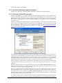
1.3.3 Overview of installation process
AVEVA Plant Installers use standard Microsoft Installer (MSI) technology, which facilitates silent
installations through standard MSI means. Target location or ROOTDRIVE can be specified by use of the
Browse button when running each installer. Please note that the use of folders with names including a
space, such as “C:\Program Files” is not recommended at PDMS 12.1. Please see section 1.3.4 below if this
is important to you.
By default, installations performed using setup.exe will be loaded on C:\ and will stop with an error if there
is no C: drive. The default location may be changed by use of the Browse… button. Alternatively, the .msi
file (e.g. PDMS12.1.1 Plant12.11.msi) can be run directly; this will by default use the writable local drive
that has the largest free space. For more details of the latter, see http://msdn.microsoft.com/enus/library/aa371372(VS.85).aspx.
The main AVEVA Plant Installer includes options to install many of the associated products, although, for
various reasons, some products use a separate installer. This means that a selection of products can easily
be installed together. This includes the AVEVA Global client option, which enables the use of PDMS or
other Plant products with Global. However, there is a separate installer for Global server, which is usually
installed on a separate machine, such as a server, which does not necessarily have PDMS installed.
There are options to install batch files and shortcuts on the desktop and/or in the start menu for direct entry
to popular modules. Please note that there is no „thin client‟ installation option as this is no longer
supported.
Existing installations should be changed, repaired or removed using Add or Remove Programs from the
Control Panel. This process will prompt for the original DVD if required. This ensures that a consistent
product set, as tested by AVEVA, will be deployed.
Fix releases (patches) will use a standard updating process, which also checks, and if necessary „heals‟, the
existing installation. There is therefore no prompt for location, as the system already has this information.
Fix releases may also be removed using Add or Remove Programs. Fix releases are applied to all
products installed together, not to the individual products. The use of the latest fix release is recommended:
this includes any previous fixes to those products.
It is important that any files, including configuration files or sample data, that need to be updated by users
are accessible for read, write etc. so it is strongly recommended that they are not installed with the software.
Copyright 1974 to current year. AVEVA Solutions Ltd.
1-2
12.1.1
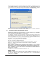
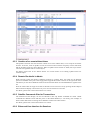
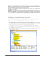
This is particularly important when installing in Program Files at Windows 7 due to the introduction of
User Account Control (UAC) which brings new security restrictions. In particular, this makes it important
to ensure that files that need to be written are accessible by users without Administrator privileges. This
applies to folders specified by environment variables such as PDMSWK and PDMSUSER. The Plant Suite
installer has been revised to allow the separate definition of suitable folders, with different defaults:
For full details of the installation options and procedure, and the hardware and software requirements,
please refer to the PDMS & Associated Products Installation Guide.
1.3.4 Installation in folders with embedded spaces
AVEVA does not recommend this – as noted in the Installation Guide. However, it is recognised that it
may be desirable to install in C:\Program Files\AVEVA\... or similar, in order to comply with common
practice. Changes have been made at PDMS 12.1 to make this easier.
From PDMS 12.0, it is possible to use spaces in filenames, using the filename command atom (enclosed in
quotes) rather than the ordinary PDMS name (starts with / and ends with <space>). However, spaces have
also been used as delimiters in search paths – between the folder names. Changes are required to the setting
of the environment variables in order to allow spaces in the file or folder names.
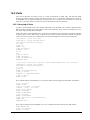
Without Spaces, an environment variable might be defined thus:
set pmllib=c:\usersappware\pmllib c:\aveva\plant\pdms12.1.1\pmllib
With spaces, a semicolon (;) delimiter should be used:
set pmllib=c:\users appware\pmllib;c:\program files\aveva\plant\pdms12.1.1\pmllib
Note that the „;‟ must still be used even if there is no search path, if the file paths contain spaces:
set pmllib=%~df1\pmllib;
Changes have been to the standard AVEVA applications (appware) to ensure that it works in both cases.
This work includes problems caused if the PDMSUSER folder is defined with spaces in the directory path.
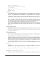
AVEVA Global daemon should work when installed in C:\Program Files provided that PDMSEXE is
defined in this way, for example:
Set PDMSEXE=C:\Program Files\AVEVA\GlobalServer12.1.1;
Batch file changes
The PDMS 12.1 installers have been changed to make it simpler to handle spaces in installation folders, by
using semicolon (;) delimiters rather than spaces. Changes have been made to environment variables,
including those set by evars.bat:
Copyright 1974 to current year. AVEVA Solutions Ltd.
1-3
12.1.1
Folder paths now end with a backslash (\)
All paths are the old DOS 8.3 format compliant, except for %pdmsexe%
%pdmsexe% is terminated with a backslash and a semi-colon (\;)
This applies to both pre-assigned environment variables and those assigned by evars.bat.
Customers who start PDMS using their own procedures may need to make similar adjustments when using
folders with spaces in their names. The following batch files, or equivalent, may need to be considered:
pdms.bat, evars.bat, projectCreation.bat, bpm.bat, diagrams.bat, engineering.bat, make.bat,
singleds.bat, multids.bat
Note: the project creation file runs the evars.bat file. If one file uses „;‟ separators for PMLLIB, all called
files must do the same. You cannot have a mixture of „;‟ separators and space separators.
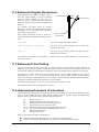
AVEVA Multi-Discipline Supports (MDS) and Area-Based Automatic Drawing Production
Similar changes have been to the batch files supplied with MDS & ABA, notably mdsevars.bat.
AVEVA Marine
Please note that the same work is less well advanced for AVEVA Marine, so this is not yet supported.
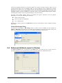
1.3.5 Projects in folders with embedded spaces
AVEVA Plant 12.1 will not fully support projects with spaces in their pathnames as Global and some
utilities such as the project MAKE program and Standalone DICE do not yet handle them. Work is in hand
to remove these limitations but no definite release date is yet set.
Copyright 1974 to current year. AVEVA Solutions Ltd.
1-4
12.1.1
1.4 AVEVA Plant portfolio
1.4.1 AVEVA Plant Version 12.1
Most of the Plant Design products were updated and re-branded at Version 12.0 to simplify the question of
compatibility. This practice continues at version 12.1; all Version 12.1 products are designed to work
together and in some cases they may also work with earlier versions.
The Plant Portfolio is now divided into 3 groups of products named after the major activities: Engineer,
Design, Manage. Many of the Engineer and Design products are built upon a common set of applications of
the AVEVA Design Platform, which includes the database technology and administrative applications.
1.4.2 AVEVA Plant Engineer Products
These schematic and engineering products create schematics, diagrams, datasheets, engineering lists and
indexes.
AVEVA Engineering
Manages engineering data in an environment shared with the main AVEVA Plant
Design tools. Its main modules are:
Tags, which manages information associated with tagged items,
coordinating data from schematics and engineering products, with the option
of viewing the corresponding data in the design products.
Schematic Model Manager, which provides unrivalled features for the
consolidation of all P&ID data for a project, independently of the P&ID
authoring tool.
AVEVA Instrumentation
Four integrated program modules support the entire Instrumentation and Control
system lifecycle – from engineering and design, through installation, maintenance
and modification. AVEVA Instrumentation may be integrated with AVEVA
Plant or AVEVA Marine, or used as a stand-alone application.
AVEVA Electrical
A new product for Electrical Engineering, based on the proven technology used
in AVEVA Instrumentation. AVEVA Electrical may be integrated with AVEVA
Plant or AVEVA Marine, or used as a stand-alone application.
AVEVA Diagrams
Used for creating P&IDs and HVAC diagrams. It saves both the diagram and the
engineering objects in the model database.
AVEVA P&ID
Stores intelligent engineering data with the graphics in an AutoCAD drawing
while the designer draws and annotates P&IDs. These intelligent P&IDs,
containing tagged items, quantities and connectivity data, can be loaded into the
AVEVA schematic model via Schematic Model Manager, or synchronised with
VPE Workbench. Supports different engineering standards, individual company
working methods, and complex projects containing many hundreds of P&IDs.
AVEVA VPE Workbench
An integrated engineering database which manages the evolving engineering
descriptions of all tagged items in a plant.
AVEVA Schematic 3D
Integrator
Integrated Schematic / 3D environment allows customers to build their 3D model
in a controlled manner, directly from information on a P&ID, enabling
consistency checks between the Schematic and 3D models.
Copyright 1974 to current year. AVEVA Solutions Ltd.
1-5
12.1.1
1.4.3 AVEVA Plant Design Products
These products focus on the layout and detail design of the plant; they create 3D models and produce all
associated deliverables.
AVEVA PDMS is the major AVEVA Plant Design product: it includes engineering applications for design
of piping and equipment, structural, ducting, cable trays and supports, including drafting. AVEVA
Schematic 3D Integrator adds tight integration with the AVEVA Plant Engineer schematic and engineering
data. It should be noted that PDMS can read data from an AVEVA Marine Outfitting database but cannot
read or write Hull data.
The main add-on applications and interfaces are:
AVEVA Multi-Discipline
Supports (MDS)
PDMS application for the design of all kinds of supports, from a complicated
framework with integral hangers to a simple U-bolt. A standard catalogue of
pads, sliding shoes, straps and clips etc. enables the design of consistent,
reliable and fully detailed hanger and support designs in the shortest possible
time. Automated production of fully dimensioned manufacturing drawings
complete with data for fabrication and erection of the support, including
Material Take Offs and cut lengths.
AVEVA Nuclear Applications
AVEVA Nuclear Concrete Design: PDMS application for the design of
complex concrete structures for nuclear power plant.
AVEVA Nuclear Room Manager: PDMS application for managing nuclear
power plant design by Room, Volume or Area.
AVEVA Nuclear Concrete Quantities: Calculation of the concrete volumes,
formwork surface areas and slab usable surface areas.
AVEVA Laser Model Interface
(LMI)
Brings as-built 3D model data into the PDMS Design environment by
interfacing with point cloud data from laser scanning systems.
AVEVA Area-based
Automatic Drawing Production
(ABA ADP)
Automated production of volumetric drawings using templates, thus simplifying
drawing update after changes to the PDMS model. Ensures that up-to-date
drawings are always available for maintenance work etc.
AVEVA Isometric Automatic
Drawing Production (Iso ADP)
Automates the production of fully annotated drawings of PDMS HVAC and
Cable Tray, including a bill of materials.
AVEVA OpenSteel
Allows import and export of files in Structural Detailing Neutral Format
(SDNF) format to and from PDMS. Used for transferring data to and from 3D
steel detailing packages such as Tekla, Graitec and AceCad.
AVEVA Mechanical
Equipment Interface –
import and export
These interfaces import and export geometric models direct to and from PDMS
equipment models using the standard STEP AP203 format; other PDMS
elements may also be exported in the same format.
AVEVA ImPLANT-I
Converts MicroStation 3D geometric model (.DGN) files for input to PDMS or
REVIEW; can also translate associated Design Review (.DRV) files for use in
AVEVA Review.
AVEVA ImPLANT-STL
Converts stereo-lithography (.STL) files from mechanical CAD systems for
input to PDMS.
AVEVA ExPLANT-A
Exports 3D geometric models from PDMS to an AutoCAD interchange (.DXF)
file, which can be used to import 3D geometric models into AutoCAD or other
suitable CAD systems.
AVEVA ExPLANT-I
Exports 3D geometric models from PDMS to a binary MicroStation (.DGN)
file, which can be used to import these models into MicroStation or other
systems such as Intergraph‟s PDS. ExPLANT-I can also create associated
attributes files in a variety of text formats, including HTML.
AVEVA Pipe Stress Interface
Two-way interface for data exchange between PDMS and the CAESAR II or
TRIFLEX pipe stress systems. Piping designers and stress engineers can
exchange design and stress information.
Copyright 1974 to current year. AVEVA Solutions Ltd.
1-6
12.1.1
1.4.4 AVEVA Plant Manage Products
These products assist the management of the plant design process. They enable global work share, clash
management and design review.
AVEVA Global
Allows project data to be synchronised between remote sites.
AVEVA Review
3D visualisation of large complex plant models, including walk-through,
animation, and high-quality photo-realistic images.
AVEVA ReviewShare
Collaboration tool that provides a method of tracking and responding to
comments and incorporates web-based access to a central 3D model.
AVEVA Clash Manager
Provides comprehensive identification, recording, trend analysis and management
of the resolution of design clashes through an approval mechanism.
AVEVA Model Management
products
Manages clash information, object status and deliverable production. Comprises
AVEVA Model Object Manager, AVEVA Clash Manager, AVEVA Connectivity
Manager and AVEVA Deliverable Manager. Clash Manager is also available as a
stand-alone product.
AVEVA PML Publisher
Allows encryption of PML scripts, thereby enabling the use but not the
modification of users‟ PDMS applications.
AVEVA SQL-Direct
Enables SQL queries on PDMS data, thereby simplifying integration of PDMS
data into Office applications such as Excel.
AVEVA QUERY
Allows PDMS applications written in PML to access ODBC databases, to read or
write their data and use it in PDMS applications.
1.5 AVEVA Plant version 12.1.1
The first general release of version 12.1 is 12.1.1 for release in September 2011.
This release includes extensive updates to the handling of local language and units of measure, as well as
many other enhancements listed in this document. A new reporting add-in (see section 4.6) also provides a
new method of publishing data to AVEVA NET.
New products at version 12.1 include 2 new Plant Engineer products:
AVEVA Engineering (based on PDMS technology)
AVEVA Electrical (based on AVEVA Instrumentation technology)
AVEVA Engineering incorporates Schematic Model Manager; it also includes a new TAGS module and a
new Engineering Database.
AVEVA Electrical and AVEVA Instrumentation are supplied separately from the main AVEVA Plant DVD;
their release may be at a later date.
AVEVA Isometric ADP (Automated Drawing Production) has been extensively updated and is now
available for use with PDMS 12.1.
AVEVA Final Designer has been withdrawn. Extensive improvements have been made to the export of
AutoCAD format (DXF, DWG) drawings from PDMS Draft.
AVEVA SQL-Direct has not been updated but works with PDMS 12.1.
AVEVA Pipe Stress Interface is not available with the initial release of PDMS 12.1.
Copyright 1974 to current year. AVEVA Solutions Ltd.
1-7
12.1.1
Copyright 1974 to current year. AVEVA Solutions Ltd.
2-8
12.1.1
2
AVEVA Plant portfolio updates at 12.1
2.1 General
These changes apply to PDMS and many of the other products based on the AVEVA Design Platform.
2.1.1 Improved local language – Unicode encoding
A major internal change at PDMS 12.1 is that the system uses the Unicode standard for text storage and
manipulation, rather than the various specific and somewhat proprietary methods that are used in PDMS
12.0 and earlier releases. This standard covers all common world languages – and special characters – and
will make it much easier to provide support for additional character sets in future. It makes text handling
more robust and makes it much easier to relax some of the previous restrictions, particularly to the use of
Asian 16-bit character sets. For example, these may now be viewed in the 3D views. Inputs and outputs
may be in Unicode or local standards.
2.1.2 Units of measure – extended range of conversions
PDMS has always provided conversions for distance and (pipe) bore measurements, to cater for the use of
both Metric and Imperial (English) units. This has allowed users to work with feet and inch input & output,
but with database storage always in millimetres. Area and volume units have been derived from the length
units. Other physical quantities have been handled as purely numeric and have had no conversions applied
to them.
PDMS 12.1 extends these facilities to a much wider range of measures, and includes built-in definitions and
conversion factors for a wide variety of units of measure, with standardised storage and efficient
conversion.
These extensions are needed to provide for the much wider range of data now being handled, particularly
for plant engineering and schematic data. These data now include Distance, Bore, Area, Volume, Angle,
Weight, Temperature, Density, Pressure, Force, Voltage, Current, Impedance, and many others.
Please note that this does mean that the behaviour of some real attributes is different; users‟ PML
applications that check or manipulate these values will need to be reviewed. Some guidance is available in
section 16.5.
2.1.3 Performance
Various application diagnostics have been improved to facilitate the gathering of performance data. Using
this information, system performance has been improved in a number of key areas, including:
Faster start up with an option to enter any module directly rather than via Monitor
GML Performance improvements for Mechanical Equipment Interface
Indexing by Type – an index (Dabacon table) to return all elements of a given type
Improved Dabacon performance, including changes to its memory „buffer‟, more efficient
claim/release and reading/writing more than one page (record) at a time – see also section 3.7.1
Work in this important area is on-going.
2.1.4 Database accuracy
The accuracy of large numbers, notably coordinates, was increased for PDMS 12.0. Coordinates should
now be accurate up to the limit of the spatial map (100 km) – but design graphics can show some „glitches‟
close to this limit. The limit in PDMS 12.0 of 21 km for Isodraft has been relaxed for this release – see
section 12.3.
Copyright 1974 to current year. AVEVA Solutions Ltd.
2-9
12.1.1
2.1.5 Application update and consistency
There are many enhancements to the user interface aimed at improving its ease of use and also its
consistency between the various different functions and disciplines. Improvements include the ability to
save 3D views, enhancements to piping functions including sloping lines, an enhanced Clasher GUI,
improved hole creation.
Changes have also been made to improve the way that the system works on Windows 7, with a variety of
different locales.
2.2 PDMS 12.1
Many enhancements detailed in chapters 9 to 12, including the following:
2.2.1 Design
Many improvements, notably to model editing, sloping pipelines, hole management and change
highlighting
A new standard model library and a much enhanced clash detection utility
2.2.2 Drawing Production
Draft
Extended line styles and hatch patterns
Improved export to CAD formats: DXF, DWG, DGN
An updated Isometric ADP add-on application
Isodraft
Improvements to Piping isometrics include TrueType fonts, new output file formats and production of pipe
spool (PSPOOL) isometrics.
2.3 Other Plant Design Products
2.3.1 Multi-Discipline Supports (MDS)
Integration with new Cable Tray features.
2.3.2 Global
Earlier releases of AVEVA Global used Remote Procedure Call (RPC) for communication between
locations. A new option to use Windows Communication Foundation (WCF) in its place was introduced
with PDMS 12.0.SP6.6. Global can now use the wide variety of security configuration options provided by
WCF, providing improved daemon security and robustness.
Global can now (optionally) propagate Linked documents which are marked appropriately. These
documents must be defined using a file URL, and any folders used must already exist.
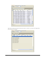
2.4 Plant Engineer Products
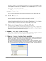
2.4.1 Engineering
A new AVEVA Engineering product has been introduced together with the release of AVEVA Plant 12.1.
This new product includes a new Tags module as well as a new Dabacon database type designed and
optimized for Engineering data. For more information, please see the “AVEVA Engineering” and
“Administration” sections.
Copyright 1974 to current year. AVEVA Solutions Ltd.
2-10
12.1.1
The Engineering product also includes the Schematic Model Manager module, which is no longer sold as a
separate product.
2.4.2 Schematics
These products include Diagrams and Schematic 3D Integrator, each of which includes a number of
enhancements in the 12.1 release and are installed with the main Plant suite. Please refer to the “AVEVA
Schematic 3D Integrator” and “AVEVA Diagrams” headings respectively.
AVEVA P&ID is also a member of Plant Engineer family, but is separately installed and has a separate set
of release notes. AVEVA P&ID is fully integrated with PDMS and can save data directly to the schematic
model database. A new release, AVEVA P&ID 12.1, will be released around the same time as PDMS 12.1.
For details of the enhancements included, please refer to the Product Release Letter
http://downloads.aveva.com/90188/d90188.pdf and the User Guide included with the product.
2.5 Sample Model data
An installer option for the Plant suite installs a variety of standard „model‟ projects, including Master
(MAS) and Sample (SAM). The old Imperial (IMP) project is no longer supplied; instead there is an
Imperial MDB /IMPSAMPLE in the SAM project.
A file (for example, SAM_Project_description.pdf) is included in each project folder giving brief details of
the purpose and data included in that project. The MAS project provides example component data and
specifications (“Component Data”). All data in the projects is provided as sample data only and should be
verified for production use.
Major changes for 12.1 include:
Improved Project_description PDF files
Conversion of all databases to Unicode (the new default)
Addition of OpenSteel test data to BAS project
Many corrections to the various catalogues and specs, including improved bolting
Piping catalogue amended for sloping pipe development
Addition of 7 segment bends and many improvements to HVAC catalogue
Addition of weights (in Kg) to ANSI catalogues & specs
Addition of flat bar to the steel catalogue
New Vantrunk catalogue; update Oglaend catalogue
Additional information for Isometric ADP
Additional information for Diagrams, Tags, Instrumentation and Electrical
A complete list of all changes logged is included in section 17.2.1.
2.6 Documentation
A great many changes have been made to the documentation set for PDMS 12.1, with all manuals updated.
Notable improvements to the documentation set include:
A new 12.0 to 12.1 Upgrade manual
A Global WCF Configuration Guide (introduced with Global WCF at 12.0.SP6.6)
Manuals for new functions and products: Report Designer, Tags, Isometric ADP
Major update for Lexicon manual
A new section on Event Driven Graphics in the Software Customisation Reference Manual
A new index page gives access to the online help system, which may also be accessed direct from the
system using <F1> as usual.
Copyright 1974 to current year. AVEVA Solutions Ltd.
2-11
12.1.1
It should be noted that the PDF manuals are no longer supplied separately but may be obtained from the online help by clicking
on entry to any manual.
2.7 Operating environment
PDMS 12.1 is supported on Windows XP Service Pack 3 (32-bit) and Windows 7 (both 32- and 64-bit
versions). Projects are usually installed on a server – both Windows Server 2003 & 2008 R2 are supported.
2.7.1 PC hardware configuration
A minimum of 4 GB of memory is recommended for this release, especially when installed on Windows 7.
PDMS 12.0 will operate with less, but system performance will be compromised. A screen resolution of at
least 1280x1024 is recommended, though most users now use either two such screens or a wide-screen
(1920x1200) display. For details, please refer to the Systems Requirements Manual.
2.7.2 Microsoft Windows
Desktop
PDMS 12.1 is supported for use on Microsoft Windows XP Professional, Service Pack (SP) 3 or on
Windows 7 (Business and Enterprise editions) Service Pack 1, with appropriate patches.
A single 32-bit version of the PDMS system is available; this is supported on both 32- and 64-bit versions
of Windows 7. It is no longer supported on Windows 2000; indeed Microsoft no longer offers support for
Windows 2000 or Windows XP SP2.
Please note that User Account Control (UAC) introduces new security restrictions at Windows 7 (and
Vista). In particular, this makes it important to ensure that files that need to be written are accessible by
users without Administrator privileges. This applies to folders specified by environment variables such as
PDMSWK and PDMSUSER, which are no longer installed by default with the program executables.
2.7.3 Microsoft Internet Explorer
Internet Explorer is required for the on-line help system; version 7 or 8 is recommended as version 9 does
not currently work correctly. See section 17.1.1.
2.7.4 Microsoft .NET Framework
PDMS 12.1 requires Microsoft‟s .NET Framework 3.5, which is supplied on the DVD and installed if
required. It should be noted that installation of version 3.5 brings with it several of the earlier versions, on
Copyright 1974 to current year. AVEVA Solutions Ltd.
2-12
12.1.1
which it depends. It is also possible to install additional versions in order to support older applications such
as PDMS 11.6, which requires .NET 1.1.
The updated version of .NET used for PDMS 12.0.SP6 onwards may prevent .NET add-ins running if
deployed on a network. This will not usually cause an issue for PDMS, for which AVEVA recommends a
local installation on each machine, but might cause problems for customers running their own add-ins.
.NET security can cause issues when running PDMS across the network where the add-in assemblies reside
on a different machine to the .NET runtime. The default security level for the local intranet is not set to Full
Trust, which means that programs may not be able to access resources on the local machine. To overcome
this, the intranet security may be set to Full Trust, though this means that any .NET assembly may run.
Alternatively, Full Trust may be given to a specified group of strongly named assemblies.
Trust levels may be set using the Microsoft Code Access Security Policy tool caspol. For details, please
see http://msdn.microsoft.com/en-us/library/cb6t8dtz(v=VS.90).aspx.
Serialization
Please note that serialized settings (of the user interface configuration) are now saved in the following
location on Windows XP:
C:\Documents and Settings\<username>\Local Settings\Application Data\Aveva\
and on Windows 7:
C:\users\<username>\Appdata\Local\AVEVA\
2.7.5 Microsoft Office & fonts
AVEVA Plant 12.1 is supported with Office 2007 and Office 2010. The use of the 32-bit version of Office,
including Visio, is recommended on both 32- and 64-bit Windows as issues have been encountered with the
64-bit version.
Excel interoperability
Import of data into a grid control requires an optional component from Microsoft Office. This is not
supplied with PDMS but is an installation option for Microsoft Office. Please ensure that “.NET
Programmability Support” under Advanced customization of applications” is enabled when Office is
installed.
This will install the Microsoft Microsoft.Office.Interop.Excel.dll. If this assembly is not enabled, invoking
the Excel import facility will not work.
Screen font for GUI
The PDMS user interface (version 11.6 onwards) requires the use of the Arial Unicode MS font, which is
supplied with Microsoft Office (version 2000 onwards) and is usually installed automatically when using
Windows XP or later.
For further information, please refer to http://office.microsoft.com/enus/help/HP052558401033.aspx. If this
font is not installed, some of the text in the PDMS user interface may become illegible.
The layout of some GUI forms may also be adversely affected if the screen font size is not set to the
smallest size, which is usually default. This setting is accessed from the Control Panel and is referred to as
“Normal” in Windows XP or “Smaller” (100%) in Windows 7.
2.7.6 Graphics cards
Due to the rapidly changing availability of hardware-accelerated OpenGL graphics cards, an up-to-date list
of supported cards is not included in the documentation released with PDMS. The AVEVA Product
Support website (accessible from http://www.aveva.com) – IT Configuration section,– contains a list of
tested and supported graphics cards.
Copyright 1974 to current year. AVEVA Solutions Ltd.
2-13
12.1.1
2.7.7 Environment variables
PDMS and some of the other products rely on the use of environment variables for various aspects of
configuration, notably the location of folders for project databases and user workspace.
There are points to bear in mind for both of these when setting up a user‟s environment:
Write access is required for folders such as PDMSWK and PDMSUSER: see section 2.7.2.
An environment variable such as SAMDFLTS, which can be set to point to an empty folder if
there is no variation from PDMSDFLTS, is required to reference a folder for storing configuration
details for each project. This is now used in several circumstances, including the start-up of MDS,
Schematic 3D Integrator or any Engineering / Schematic product.
The installer will now use different default locations for the program files and some of these data folders.
Additional dialogs enable the user to control these better.
2.8 Upgrading from earlier releases
2.8.1 Upgrade overview
A number of the enhancements made at PDMS 12.1 require an upgrade to the database. Each of these
individual changes is referred to as a Part Upgrade. In normal use, the whole project will be upgraded to the
latest version, though each part upgrade are in general designed to be „optional‟, in that the 12.1 software
can work with a database that has not been upgraded and the software will degrade gracefully – that is, the
software will continue to work, although some new functions may not be available.
This means that it is possible for customers to continue to work with Foreign DBs, which may be shared
with 12.0 or earlier projects and which have not been upgraded, included in their projects. An example
would be a Corporate Catalogue DB used for 12.0 and multiple projects.
Databases which have not been upgraded will however be read-only. The following warning will appear
when opening an MDB from a project that has not been upgraded:
This warning (or similar) indicates that the project needs to be upgraded to the latest version in order to
allow write access.
All the Part Upgrades will be run by a DBUPGRADE command, which converts a PDMS 12.0 project to
12.1. This is initiated from Admin using the following commands in the Command Pane (or TTY mode):
lock
dbupgrade project to latest
unlock
This procedure may also be used with Global projects if some additional precautions are taken. A brief
summary is given below – further details are given in the 12.0 to 12.1 Upgrade manual.
Earlier projects should first be upgraded to PDMS 12.0.
Schematic Model Manager has its own units handling at PDMS 12.0. It also has its own upgrade
mechanism, which is separately documented; the software will advise if it is necessary to run this:
Copyright 1974 to current year. AVEVA Solutions Ltd.
2-14
12.1.1
2.8.2 DBUpgrade command
The Upgrade procedure is invoked from Admin; it controls the upgrade process and runs each Part Upgrade
in the appropriate order. Upgrades relevant to PDMS that are covered by this process are:
UKEYs (now include database number to avoid duplicates)
Performance of „finding‟ database elements (index by type)
Module Definitions – new TAGS module (and renamed Marine Drafting module)
Character handling (Unicode representation for names, text etc)
Line widths in Draft (widths of thin, medium and thick lines now stored in system database)
The upgrade process puts an upgrade number in the databases, indicating the level to which they have been
upgraded. This makes it easy to detect, on opening, whether a database has or has not been upgraded. This
upgrade number will also be used by the Reconfigure process.
2.8.3 Database Version Control
The upgrade version number is used to verify that the versions of the database and the software that
accesses them are compatible. During application start-up, databases are checked against the software;
access may be restricted according to the following table:
Pre 12.1
Software Version
Pre 12.1
12.1.1
Future (e.g. 12.2)
R/W
R
R
Database Upgrade Version
12.1.1
Future (e.g. 12.2)
Max Open Mode
X
X
R/W
X
R
R/W
This control ensures that AVEVA software that opens a database is compatible with the contents of that
database and thereby prevents accidental data corruption. It also ensures that data intended for use with one
software version is not modified by a newer, incompatible software version.
X indicates „no access‟; however, versions earlier than 12.1 do not make this check, so cannot detect a
database upgraded to 12.1 or later.
2.8.4 Global
It is recommended that the whole project, excluding Foreign databases, should be upgraded at once.
However it is recognised that this needs to be achieved in stages, and different locations and databases can
be upgraded independently of each other.
It is not necessary to disable automatic update events. Global can continue to work as normal during the
upgrade procedure.
Databases can only be upgraded at their primary location. Project upgrade will ignore secondary databases
including databases which are undergoing re-location, as well as extract hierarchies which contain
secondary extracts.
All extracts of any database must be upgraded as a group. It is not possible to upgrade a single master or
extract independent of the remainder of the extract hierarchy. In a Global project, this requires the extracts
to be relocated to the primary location of the master.
In ADMIN, the Upgrade Status query (Q UPGRADE STATUS) provides additional information on
secondary databases and those which own secondary extracts.
Global cannot upgrade extract hierarchies which contain working extracts at more than one location, and it
is not possible to relocate working extracts. It is recommended that these should be deleted before upgrade
(after data has been flushed). If all working extracts are at a single location, this location should be used to
upgrade the master and its extracts.
2.8.5 The Upgrade Process
The upgrade process will be undertaken by System Administrators responsible for the project at all
locations. When upgrading multiple projects, many System Administrators will need to co-ordinate. The
upgrade process will upgrade one project at a time. Customers will need to give careful consideration to the
order of upgrade for the various projects.
Copyright 1974 to current year. AVEVA Solutions Ltd.
2-15
12.1.1
The projects will need to be locked for the duration of the upgrade, with all Users out of the system.
The upgrade process will be:1.
2.
3.
4.
5.
6.
7.
8.
9.
10.
11.
12.
13.
14.
15.
16.
17.
18.
Ensure all users have exited from project
Lock project at all locations (upgrade will check for this (see below)
Disable Automatic update events if required. (Recommended but not essential)
Expunge all users in the system at the local location
Flush data from Working extracts – these will not be considered; in Global projects they should be
deleted
Check project using DICE (Integrity Checker)
[If DICE reveals issues, address them, then re-run DICE]
Administrator may want to unlock project while DICE issues are being addressed, but will need to
exclude all users and Lock project again before final DICE check
[After clean DICE check]
Back-up project at all locations
Temporarily relocate all non-Foreign DBs to their master‟s Primary location
Check for No Transient Databases
Upgrade the project at each location
Optionally Merge Sessions
Optionally Reconfigure for Unicode
DICE check project
Relocate extracts back to their original locations
Perform non-framework upgrades if applicable
Unlock the project
2.8.6 Locking the Project
The project as a whole cannot be locked, only individual locations; however, it is possible to lock all online
locations from the HUB through Global. To do this run the following command from the HUB:
LOCK AT <location>
The HUB can be locked without the need for a daemon command using the command:
LOCK
It is possible to confirm whether locations are locked by evaluating the return result from:
QUERY LOCK AT <location>
The Hub can also unlock satellite projects:
UNLOCK AT <location>)
2.8.7 Extract Hierarchies
It should not be necessary to change the extract hierarchy, nor to consolidate data within extract hierarchies.
Therefore the System Administrator should not need to FLUSH, ISSUE, DROP data between extracts
(working extracts are an exception to this – see below). Nor should they need to delete any extract families
to leave only Masters. However all extracts will need to be relocated to a single location, although this does
not need to be the HUB.
Working Extracts
Working Extracts cannot be propagated as they are specific to a single location. See note in section 2.8.4.
Offline Locations
Global supports Offline locations without a Global connection. Offline locations do not support distributed
Extracts but can support stand-alone extract families.
It will not be possible to co-ordinate the upgrade from another location if Offline locations are used. The
Offline satellite databases (and standalone extract families) will need to be upgraded there, and data
transferred to the hub in the normal way.
Copyright 1974 to current year. AVEVA Solutions Ltd.
2-16
12.1.1
2.8.8 International characters (Unicode)
New text files, including Datal files, will be output by default in UTF-8 with a BOM, unless the
CADC_LANG_NEW environment variable is set. Datal files written from earlier versions will not be UTF8 but will be read according to the CADC_LANG environment variable or Latin-1 if unset. If this is
incorrect, this could cause encoding problems causing the file to be misread. For further information, please
see sections 4.1 and 16.1.
New databases created at PDMS 12.1 will by default use the Unicode character set for textual attributes and
names – see section 3.1. However, no upgrade is required for older databases: they will be handled
according to the project character set as defined in Admin (PROJECT CHARSET or PROJECT
MBCHARSET commands). They will also be converted according to this setting if they are reconfigured
so it is important that it is set correctly!
In cases where an extended range of characters is needed, Reconfigure may be used to convert a „legacy‟
database to a Unicode encoded database.
In the following example legacy DICT databases (used to hold UDA and UDET names) are reconfigured to
be Unicode encoded, using Admin 12.1.
FROM DB MASTER/DICT
TO FILE /c:\DICT1 /c:\DICT2
RCFCOPY ALL
RECONFIG SESSIONS
FROM FILE /c:\DICT1 /c:\DICT2
TO DB MASTER/DICT
RECONFIG
Doing it this way means that no deletion and recreation (or copy) is required for the DB, and therefore
neither is re-adding to the MDB structures required. Using RECONFIG SESSIONS in the FROM phase of
the reconfigure operation will preserve both the sessions and references.
Summary
Locally Encoded (Legacy) Databases:
• can be opened for read access in both PDMS 12.1 and earlier versions of PDMS
• can be opened for write access in both PDMS 12.1 and non-Unicode versions of PDMS, but the
range of characters which may be used is restricted to the set defined by the project settings
• require that the project settings are correct so that characters can be interpreted correctly
• can be reconfigured to a Unicode encoded database
Unicode Encoded Databases:
• cannot be opened for read or write access in versions of PDMS prior to 12.1
• can store the full range of Unicode characters available in PDMS 12.1
2.8.9 Units of measure
Distance and bore units are handled in much the same way as before and should need no conversion. Other
attributes will now be converted to and stored in appropriate units. The table in section 4.2.1 shows the
database units which are used; they are thought to be the most commonly used unit. Where a database has
stored all quantities of a dimension in the appropriate unit, the new functions can be used without upgrade.
Attributes other than distances and bores have the UNIT field set for the first time; in previous versions of
PDMS, they were until now stored as values with no specified unit, other than by use and convention - they
could change from application to application, and project to project. This approach is not compatible with
automated conversion so the storage units must be defined. For compatibility, it is possible to set the units
to NUMERIC which will disable Units conversion for that physical dimension. Disabling a specific
dimension in this way means that no advantage will be gained from the introduction of that dimension.
Previous versions of Schematic Model Manager had special units support for Angle, Area, Pressure,
Temperature, Volume and Weight values that could be included in the ISO15926 format import file. Units
UDAs were provided as mandatory UDAs and were attributes on each Diagram element (SCDIAG). The
chosen units for these dimensioned quantities could be set in the Project Options form in Schematic Model
Manager. In 12.1, the new units capabilities mean that the special units support in Schematic Model
Manager is no longer required. Data imported in 12.1 will be stored in the appropriate units consistent with
Copyright 1974 to current year. AVEVA Solutions Ltd.
2-17
12.1.1
the data read from the ISO15926 import file. The upgrade process for projects moving to 12.1 includes a
part upgrade for Schematic Model Manager dimensioned data.
Please note that the CATA database elements MSET, MTYP, ATLI, USEC and UDEF are no longer used;
they will be removed from the database in due course.
2.8.10 Schematics functions
Projects that are upgraded from PDMS 12.0 or earlier need a suitable module definition in order to use the
new Engineering functions in the new Tags product (see above).
The data will need some reconfiguring:
Integrator links world (CYMWRL) has been moved to Reference database
Shape upgrades in Diagrams – automatic when opening a diagram in write mode
Systems moved to Reference Design database
2.9 Compatibility
2.9.1 AutoCAD
This release of AutoDRAFT supports AutoCAD releases 2007, 2008, 2009 and 2010. Note that
AutoDRAFT no longer supports AutoCAD 2006 for languages other than English.
2.9.2 Final Designer
Final Designer is no longer supplied with PDMS; the latest version supports only AutoCAD 2006 and
works with PDMS 11.6 or 12.0 on Windows XP only.
Extensive improvements have been made to the Configurable DXF, DWG and DGN output capabilities of
Draft to provide an alternative means of producing well-structured CAD deliverables.
2.9.3 Data Access Routines (DARs)
Any customer programs using PDMS Data Access Routines (DARs) will need to be recompiled and
relinked with the PDMS 12.1 libraries. Please note that text attributes are now returned in the Unicode
UTF-8 format, regardless of whether the database is in „legacy‟ or Unicode format. In previous versions of
PDMS, they were returned in „internal‟ format. This change:
is of importance mostly to customers using character sets other than Latin-1, though any accented
characters not in the basic Latin (ASCII) set will also be affected.
gives a more standard, and hence more useful, format for most customers but may be converted to
„internal‟ format (or other supported format) using the „Transc‟ utility – see section 16.1.2
2.10 Notice of change in support status
The support status for all full releases of PDMS is shown on the AVEVA web-site. The release of PDMS
12.1 will trigger a change of status for PDMS 11.6 to „Limited‟ in 2012, after a transition period of 6
months. At the same time, versions of PDMS 12.0 prior to SP6 will change to „Inactive‟.
2.11 Future considerations
2.11.1 Access platforms, Stairs and Ladders (ASL)
The new application for Access platforms, Stairs and Ladders (ASL) is being improved to provide an
excellent tool for stairs (single flight in the first release), ladders and hand-railing. Its facilities for
modelling access platforms have been removed and will be covered by a simpler approach using the new
Standard Model Library.
The new application will therefore be known as Stairs, Ladders and Hand-railing.
The old Access platforms, Stairs and Ladders application (from PDMS 11.6) is still available, though it will
be removed at a future release. It is available, hidden, at PDMS 12 and can be reactivated by a simple edit
Copyright 1974 to current year. AVEVA Solutions Ltd.
2-18
12.1.1
to the PML file PDMSUI/des/addins/access. This file is all commented out; activate all the code lines
after the header and ensure that the application is shown on the menu:
showOnMenu: TRUE
2.11.2 Hangers & Supports (H&S)
The recommended application for Pipe Hangers & Supports is the Multi-Discipline Supports (MDS) addon product. The old Hangers & Supports application will be removed at a future release but is available,
hidden, at PDMS 12.1. It can be reactivated by a simple edit to the PML file PDMSUI/des/addins/supp:
This file is all commented out; activate all the code lines after the header and ensure that the application is
shown on the menu:
showOnMenu: TRUE
2.11.3 PDMS Plotfiles
The PDMS plotfile format has served its users well over the years but has remained unchanged for many
years. Its scope is quite limited and it cannot cope with some of the more complex documents we now wish
to produce. In particular, it cannot handle text that uses TrueType fonts.
It was decided that it was more sensible to adopt one or more standard formats rather than extend the plot
file. Any existing programs using the plotfile would in any case have to be radically changed.
PDMS 12 can output Adobe‟s PDF, the Windows enhanced meta-file (EMF) and a variety of bit-map
formats such as TIFF. Ii is anticipated that the use of plotfiles in PDMS will largely be replaced by the
EMF and its use for output by PDF. The EMF is an integral part of Windows and its printing system; its use
will have the effect of opening PDMS to the use of EMF from other sources, for some purposes. The full
details have yet to be assessed and will be announced in due course.
It is proposed to drop the plotfile option at the next major release of PDMS.
Copyright 1974 to current year. AVEVA Solutions Ltd.
2-19
12.1.1
Copyright 1974 to current year. AVEVA Solutions Ltd.
3-20
12.1.1
3
Database changes
3.1 New Database types
3.1.1 Engineering Database
The new ENGI database holds engineering data that does not normally appear on the schematics drawings.
It therefore holds more detailed information necessary to fully specify the engineering equipment in a plant.
For example, a schematic diagram might show a pump, its name and its major connections – and perhaps a
little more. The engineering database will include electrical data (for the motor, loading calculations etc),
process data (the process conditions), mechanical data etc.
These data may be owned and controlled by several different discipline engineers. This database will make
it easy to work with lists of equipment and other tagged items. Using a separate database makes it simpler
for the schematics and the engineering data to be compiled in parallel – and later checked for consistency
by using the new Compare/Update utility.
While the Schematics database is optimized for P&ID data structures and is based on a hierarchical
connectivity model similar to the 3D data model, the Engineering database is instead designed to be used
for managing tagged items and keeping list type data. This also includes the option of using the new
Distributed Attributes mechanism to achieve parallel and concurrent access to discipline specific data.
The Duplicate Names mechanism allows items in an Engineering database to have the same name as items
in the Schematics and Design databases. See section 3.4” Duplicate names” for more information.
3.1.2 Design Reference database
This is a restricted Design database, used mainly for
administrative purposes – it cannot include any SITE (or
HULL) data. Its main use is for storing information about
Systems and Areas for use in Engineering and Schematics
applications. It is therefore useful for users who are
licensed only for 2D applications.
It is created by setting a flag on the database when it is
created; this is the only way to create it and the flag
cannot be removed at a later date.
Points to note about Design Reference databases:
Engineering or Schematics users can use them
They cannot be the default DB in an MDB
They cannot include SITEs; this also prevents the
creation of elements below SITEs
They can include Schematic-3D link elements,
making link information available in Schematics
products when their users do not have access to
normal DESI databases
Copyright 1974 to current year. AVEVA Solutions Ltd.
3-21
12.1.1
3.2 Access to databases
The complete list of database types, apart from „system‟ types, is now:
Administrative: DICTIONARY, NSEQUENCE
Parts catalogue and material properties: CATALOGUE, PROPERTIES
3D Design and Drafting: DESIGN & DESIGN Reference, DRAFT (PADD), ISODRAFT
Schematics and Engineering: DESIGN Reference, SCHEMATIC, ENGINEERING
In addition, MANUFACTURING and NSEQUENCE database types are primarily used by the Marine
products.
Access to the various types of database depends on the product and module being used as well as a user‟s
access as determined by his team membership and any Data Access Controls in use. In summary:
All AVEVA Plant products have full read/write access to the administrative and catalogue data in the
DICTIONARY, CATALOGUE, NSEQUENCE and PROPERTIES databases.
PDMS users can read & write 3D (DESIGN, DRAFT and ISODRAFT) databases; those who need to
access Schematic or Engineering data also need a Schematic 3D Integrator license. The decision to
work in “Integrated” mode is taken when a user enters PDMS and applies to the whole session.
Diagrams users can read & write SCHEMATICS databases; they can read but not write 3D databases.
Diagrams users can also read (but not write) the new ENGINEERING database (see below).
Engineering users can read & write both Schematic and Engineering data; they can also read (but not
write) 3D data.
The table below summarises this:
Products and corresponding database access
Database type
PDMS
(or Outfitting)
PDMS
Integrated mode
Diagrams
Engineering
Admin (DICT, NSEQ) &
Catalog (CATA, PROP)
RW
RW
RW
RW
3D (DESI, PADD, ISOD)
RW
RW
RO
RO
SCHE
None
RO
RW
RW
ENGI
None
RO
RO
RW
Key concept
Access to a product’s own databases is Read-Write (RW)
Access to other products’ databases is Read-only (RO)
Existing users of Diagrams, Schematic Model Manager and Schematic 3D Integrator will require an
updated license file.
Copyright 1974 to current year. AVEVA Solutions Ltd.
3-22
12.1.1
3.3 Increase in number of databases
A larger number of databases can now be used in a project; the new limit is 250,000. New database
numbers from 250,001 to 255,000 are reserved for AVEVA use, as well as those from 7,001 to 8,000.
It is now easier to avoid database number conflicts when databases are shared between projects. These
conflicts may be avoided by creating DBRange elements to define the range of database numbers available
for use in each of the projects. The database numbers may be between 10,000 and 250,000; these numbers
may also be used explicitly in a project that does not use DBRanges.
A DBRange may be created in Admin under the STAT element in the SYSTEM or GLOBAL database and
defines the start DBRBEG and end DBREND of a range of numbers.
There is a new “UNIQUE” option for the CREATE DB command to allow the user to create the next
database in the defined range for the project; a new pseudo-attribute NXTDBU gives the next database
number within the range.
For full details, please refer to the Administrator User Guide and Command Reference Manual.
3.3.1 Admin GUI
To create a DB Range, a menu in the Settings pull down takes the user to a new form to set values for a DB
Range. If no range already exists, this will create an unnamed DB Range and populate it with the specified
values; if more than one range is required for the project, these should be created on the command line.
leads to:
A Unique button for DB Number on the Create Database form ensures creation of a database within the
project‟s range: see picture in section 3.1.2.
3.4 Duplicate names
In general, AVEVA Plant products prevent the use of duplicate names within the current MDB. However, it
may be desirable for Engineering or Schematics elements to use the same name as the 3D elements in the
Design database. PDMS 12.0 allowed name duplication between the DESI and the SCHE databases.
It is now possible to create or rename an element in an Engineering (ENGI) database to have the same
name as any element in any Schematic (SCHE), Design (DESI) or Marine Production (MANU) database in
the current MDB.
Similarly it is now possible to create or rename an element in any Schematic (SCHE), Design (DESI) or
Production (MANU) database to have the same name as any element in any Engineering (ENGI) database
in the current MDB.
Copyright 1974 to current year. AVEVA Solutions Ltd.
3-23
12.1.1
3.5 Flexibility of data organisation
3.5.1 Database views
Database views provide a way to consolidate data from elements and attributes distributed across databases
in an MDB. These views are set up by an administrator using the Database Views Editor and stored in the
Lexicon (DICT) database in a „Database View World‟ (DBVWWL/D). Users‟ database views may also be
saved in a local settings file.
The Editor is currently available in the Lexicon module, under Display > Database Views Editor, as well
as in the Admin ribbon tab in the Tags module. Further information is given for Lexicon in section 6.4.3.
A Database View uses a table to define a view of the data, which may be derived from a single or multiple
elements. There is a row in the Database View table for each element of a particular type that meets the
criteria defined by filters. These filters use the same concept as the search grid. If the criteria cannot be
expressed using attribute filters, it is also possible to define an expression for evaluation. A row is present
in the table only if all the filter criteria are met.
This is a very powerful technique which can be used to derive data structures for a variety of purposes, in
particular List definitions in the Engineering Tags module, as well as for the new reporting function – see
section 4.6. The Excel Import/Export functions also work with Database Views, which are of particular
importance in the integration of engineering, schematic and design data.
3.5.2 Distributed attributes
Distributed attributes enable the definition of objects that have groups of attributes distributed across
databases, currently restricted to the DESIgn and new ENGIneering database types. This enables a number
of new possibilities:
Improved concurrency
o Several users may work in parallel on an object, using different sets of data
o Simultaneous multi-discipline updates on the same object are possible
o Claims may be smaller, only claiming the relevant “portions” of an object
Distribution of an object‟s attributes across hierarchies and databases
o Easier distribution using Global
o Reduced need for Global extracts
Simplified access control
o It may be sufficient to use database ownership (by teams)
Data may be included or excluded by database
Extensibility of data structures – an alternative to direct use of UDETs and UDAs
A „binding‟ element is used to achieve this: it may bind any number of bound elements, but these bound
elements can only bind to one binding element. The attributes defined on the bound elements are then
available on the binding element for both querying and manipulation.
Details of the configuration and use of distributed attributes can be found in the Database
Management Reference Manual and Lexicon User Guide.
3.5.3 Handling of duplicated names of UDAs and UDETs
UDA keys now take into account database number to remove the possibility of conflicts between UDA
names in different databases. In previous versions, this could occur when merging data from different
projects or MDBs.
A new command in Lexicon allows a user to reallocate existing UKEY values to the new format for UDAs
and UDETs. They can operate on either a selection of UDAs and UDETs or all in the current MDB. The
old keys are stored in the attribute OLDKEY for reference. Admin commands allow update of project data
to use the new keys.
For details, please refer to the Lexicon and Admin Command Reference Manuals.
3.5.4 Top-level element creation in specific database
It is now simpler to ensure that top level elements are created in a specific database; a DB keyword and
name can be added to the NEW command:
Copyright 1974 to current year. AVEVA Solutions Ltd.
3-24
12.1.1
NEW element_type element_name DB database_name
where element_name is also optional; database_name is a full database name, i.e. team/database.
For example, this command will create a new SITE named /MYSITE in the MYTEAM/MYDB database:
NEW SITE /MYSITE DB MYTEAM/MYDB
3.6 Dynamic Groups
A PML1 collection expression, evaluated whenever the group is used, may now be used to define a
selection for a GPSET. The SCOSEL attribute is used to store this selection, for example:
SCOSEL ALL EQUI FROM CLAIMLIST
More complex dynamic selections are possible, for example:
ALL PIPE WHERE (BORE GT 80)
ALL BRAN MEMBERS WHERE (SPREF EQ /MYSPEC) for SITE /SITE1
There is a performance overhead in evaluating more complex selection expressions.
3.7 Database performance
A number of enhancements have been made to the performance of the Dabacon database – see also section
2.1.3. Those noted here are the most visible to users.
3.7.1 Dabacon buffer
The Dabacon buffer is used for temporary storage of data in local memory and can therefore have a
significant effect on performance. Increasing its size is likely to reduce the amount of network I/O, so in
generally a larger buffer will improve performance. However if it is larger than the available memory,
paging will increase, thus offsetting some of the advantages.
Previous versions of PDMS 12 have limited the buffer to between 32,000 and 51,200,000 (integers) with a
default of (in general) only 12,800,000. This corresponds to a default of 50 and a maximum of 200 Mbytes;
with modern PCs, most customers found it best to use the maximum value, set by use of the BUFFER
command in Admin.
These values have been increased at PDMS 12.1; it may now be set to between 20 Mbytes and 1 Gbyte.
Default buffer size
The default buffer for modules in a new project is now:
Monitor
20 MBytes
Admin, Specon, Propcon, Isodraft, Lexicon
DARs, Toolbox
200 Mbytes
Design, Draft, Paragon, Spooler
Diagrams, Schematic Model Manager, Tags
500 Mbytes
Specifying the Buffer Size
The buffer may be set in Admin for each module or by use of an environment variable for all modules.
Buffer setting for each module in a project
The setting for each program module is usually performed using the modmac.mac file during project setup.
At a later date, the ED MOD command may be used to change its value for one or more modules.
The value may be specified in Mbytes or integers; 256000 integers means the same as 1 MByte. For
example, ED MOD DESIGN 12800000 is the same as ED MOD DESIGN 50 Mbytes
Buffer setting per user
Copyright 1974 to current year. AVEVA Solutions Ltd.
3-25
12.1.1
The Dabacon value may be set for a particular user by setting the environment variable „PDMSBUF‟ before
running PDMS. This sets the buffer size in Megabytes for use by all PDMS modules; it will be ignored if
its value is greater than 1000. For example, set PDMSBUF=500 sets it to 500 MByte.
Querying the amount of unused buffer
This may be queried using the command: Q DABACON AVAIL.
3.7.2 Dabacon index tables
The use of Dabacon index tables has been extended to speed up selection by type, UDET or UDA value.
3.8 Units of measure
This enhancement (see section 4.2) enables PDMS to store attribute data in standard units and perform
conversions as appropriate. The system handles this automatically dependent on the units and also stores
appropriate information with parameterised attributes to enable them to be handled.
A new dynamic UNIPAR attribute has been added to all catalogue elements with PARA attributes –
namely SCOM, SPRF, JOIN and FITT – and to all design elements with DESP attributes. It is a hidden
(VISI FALSE) integer array attribute (that may not be listed or queried) and holds the set of WORD unit
values corresponding to the dimensions of the values in a sibling PARA or DESP attribute.
3.9 Unicode storage of name and text attributes
The switch to Unicode (see section 4.1) means a change to the way that text is stored in the database (DB).
DBs created using 12.1 onwards will use Unicode; existing DBs will continue to work and will not be
changed until reconfigured. The data (elements & attributes) from old DBs will be converted, as required,
according to the character set (CHARSET) used for the project.
3.10 DRAFT Line-style world hierarchy
System line-style widths are now stored in the system database, for consistency throughout a project, and
are initially set to ISO defaults: Thin=0.25mm, Medium=0.35mm, Thick=0.70mm.
3.11 Extract Control – Include flush capability
Enhancements have been made to Extract Control in the Design/Engineer modules Design, Diagrams and
Schematic Model Manager. When working in an extract database, issuing, flushing or dropping an element
that has a referencing Integrator link will automatically include the link object.
The new reference array attribute INCFLU (include flush) returns any Integrator or Status link elements
that reference the current element. Flushing, issuing or dropping an element with referencing link objects
will act on those link objects even if the element itself is not claimed or modified. The Extract Control form
will display an “R” label on such elements.
Copyright 1974 to current year. AVEVA Solutions Ltd.
3-26
12.1.1
Copyright 1974 to current year. AVEVA Solutions Ltd.
4-27
12.1.1
Copyright 1974 to current year. AVEVA Solutions Ltd.
4-28
12.1.1
4
General System Changes
4.1 Unicode character handling
Earlier versions of PDMS handled textual data such as element names, textual attributes and file names in a
manner specific to the various supported character sets used in supported languages. This applied to most of
the input, output and storage. This has now changed; all textual information in PDMS is represented as
Unicode.
Unicode is a computing industry standard for the consistent encoding, representation and handling of text
expressed in most of the world's writing systems. Developed in conjunction with the Universal Character
Set standard and published in book form as The Unicode Standard, the latest version of Unicode consists of
a repertoire of more than 109,000 characters covering 93 scripts. For more details, please see:
http://en.wikipedia.org/wiki/Unicode.
Unicode can be implemented using different character encodings. The PDMS Internal Format for string
data is Unicode UTF-8 format. This can handle all seven character sets supported in previous versions of
PDMS – and potentially many more.
4.1.1 Restrictions
PDMS has been tested using the same range of languages as previous releases. No PDMS font files are
available for any other language; this means that TrueType fonts must be used on drawings and that
therefore it is not possible to produce plotfile output.
With that restriction, it is anticipated that many other languages will work, though there are aspects of the
Unicode standard that are not yet implemented. PDMS currently handles the following correctly:
Left to Right languages; and therefore not, for example, Arabic and Hebrew
Pre-composed characters; for example, the
but not the
Upper and lower casing of characters, where both cases have the same number of bytes
4.1.2 Textual File handling
By default all sequential text files read by PDMS will be expected to be in UTF-8 format with a Byte Order
Mark (BOM) present to identify them. This includes PML files, Datal files etc. Similarly by default all
sequential text files written by PDMS will be in Unicode UTF-8 format with a BOM present. Further
information about changing these defaults is given in section 16.1.1.
A simple command line „transcoder‟ is also supplied; this may be used in some applications to convert files
to a different encoding – see section 16.1.2.
4.1.3 Filenames and PML
The PDMS command processor supports Unicode characters. All PML string variables support Unicode
values. You can use Unicode characters in PML variable names, PML object form and gadget names, PML
method and function names. It is recommended that PML language files should either be UTF-8 format
with a BOM present or else strictly ASCII (basic Latin) format. AVEVA application (appware) files are
mostly ASCII at present.
Filenames and directory names can also contain foreign Unicode characters, but may cause problems in
other systems so it is recommended to keep to ASCII names. This applies to some of the systems to which
PDMS is interfaced, and even to some of the interfaces where PDMS makes use of third party software
such as output of DXF and DGN. PML Publisher does not currently fully support Unicode filenames.
AVEVA has also encountered problems using files with non-ASCII names in some development tools.
Further information is given in the PML section 16.1.
Copyright 1974 to current year. AVEVA Solutions Ltd.
4-29
12.1.1
4.1.4 Using Forms and Menus
The default „system font‟ used by PDMS Forms and Menus (F&M) is Arial Unicode MS which contains a
large number of the world‟s alphabets. Internally F&M uses Unicode, but can only display the characters
accessible in its current „system font‟. You will be able to copy and paste Unicode characters from and to
textual fields of F&M gadgets. This includes entering characters into the PDMS command window.
4.1.5 Using TTY mode
You can enter Unicode characters in Teletype (TTY) mode, but the Console Window can only display the
characters which exist in its currently selected font. Console fonts tend to be quite restrictive so you need to
select a suitable one. In the UK you will probably be restricted to “Lucida Console” or “Consolas” which
will display European characters but not Asian characters etc.
4.1.6 PDMS Databases
Unicode encoded databases
New databases created with PDMS 12.1 will, by default, store text using Unicode encoding; these may be
termed “Unicode encoded Databases”. In these databases, Unicode can be used for Names of UDAs,
UDETs, Databases, MDBs, users, teams and date stamps.
However, there are still some restrictions:
Names of System Attributes and Elements are ASCII only
„Word‟ type attributes continue to be restricted to A-Z
Some other text attributes are restricted to ASCII only
In particular, the following Project oriented attributes are restricted to ASCII only, at this release:
Filenames for databases
LOCID remains explicitly at 3 alpha-numeric characters
Project code remains explicitly at 3 alphabetic characters
Project ID is limited to 8 alpha-numeric characters
Project Number is an attribute of 17 characters (recommended to be the same as Project ID)
Project EVAR is Project code + „000‟ – so is 6 alpha-numeric characters
Legacy Databases
Old Databases created prior to PDMS 12.1 store names, text attributes and other text strings using an
encoding determined by the project settings. This determines the range of characters that may be present.
These may be termed Locally encoded or Legacy databases since the project settings are set to match a
specific locale (Russian, Chinese etc).
Legacy databases are restricted, as before, to one of the 3 Latin/Cyrillic character sets or Latin 1 and one of
the 4 Asian character sets. By default, the encoding is ASCII ISO8859-1 (“Latin 1”).
These legacy databases do not need to be modified or upgraded to be used in PDMS 12.1. They may be
opened and read from (e.g. as Foreign Databases) without restriction, since the Unicode standard
encompasses all existing local encodings. They may also be written to, with the restriction that character
data may only contain characters in the project-defined encoding. An attempt to write an invalid character
(e.g. a name containing a Chinese character into a Russian database) will be rejected with an error.
Unicode encoded databases cannot be opened (for reading or writing) with earlier versions of PDMS.
However, is also possible to create locally encoded databases if it is required that they should be accessible
by previous versions of PDMS.
If you need to extend the range of characters in a legacy database, RECONFIGURE may be used to convert
it to a Unicode encoded database.
DBTE is a pseudo-attribute on all element types which will return the encoding of the database containing
that element; for example, „Q DBTE‟ on its own will return the encoding of the database containing the
current element, „Q DBTE OF /PIPE1‟ will return the encoding of the database containing element /PIPE1.
ENCODB is a pseudo-attribute on the database (DB) element type only, which returns the encoding of the
corresponding database. In either case, the encoding is given as either „Unicode‟ or „PDMSInternal‟ for
legacy databases.
Copyright 1974 to current year. AVEVA Solutions Ltd.
4-30
12.1.1
In the case of legacy databases, the actual encoding in which text is assumed to be stored is provided by the
project settings (as in previous releases, no change). It is important that a project containing any legacy
database (either directly or as a foreign database) has the correct project settings to ensure that character
data is interpreted correctly.
Summary:
Locally Encoded (Legacy) Databases:
• can be opened for read access by both PDMS 12.1 and earlier versions of PDMS
• can be opened for write access by both PDMS 12.1 and earlier versions of PDMS, but the range of
characters which may be used is restricted to the set defined by the project settings
• require that the project settings are correct so that characters can be interpreted correctly
• can be reconfigured to a Unicode encoded database
Unicode Encoded Databases:
• cannot be opened for read or write access in earlier versions of PDMS
• can store the full range of Unicode characters available in PDMS 12.1
4.1.7 Graphical output
In general PDMS graphical output (2D and 3D) allows only the use of the TrueType fonts set up in the
Admin module. This will allow you to display Unicode characters which are known to those fonts. By
default you get font 5 = “Arial Unicode MS” which gives a large range of character sets.
Restrictions using Draft and Isodraft 2D views
For TrueType fonts, the TrueType font selected must have the correct character set(s) present for the
language(s) you want to use. Arial Unicode MS has most, but other TrueType fonts typically have a subset.
In this case, foreign and mixed language strings will work correctly.
You can of course use fonts specific to a given language for Unicode characters in that language (even if
the font name itself is in a foreign character set).
It is recommended that you avoid using PDMS (Wigwam) fonts if possible. It is not, in general, possible to
have mixed language strings if you use them. They are more complicated to setup, and work more like
12.0, so are limited compared with TrueType. The following restrictions, some of which were documented
in previous versions of the PDMS Installation Guide, apply:
Far Eastern languages, Russian and Hungarian (PDMS fonts)
1.
Set the environment variable CADC_LANG
to Korean, Chinese, TChinese, Japanese, CP1251 (for Russian) or LATIN2
2.
Enter admin and change the project to the correct language, one of:
PROJECT
PROJECT
PROJECT
PROJECT
PROJECT
PROJECT
3.
MBCHARSET JAP
MBCHARSET KOR FILE /whgtxtd BOLD /whtgtxt
MBCHARSET CHI
MBCHARSET TCHIN FILE /Chineset
CHARSET LATIN CYRILLIC
CHARSET LATIN2
(for central European Languages)
For Russian and Hungarian, change the appropriate font families, for example:
FONTFAMILY 1 LATIN CYRILLIC STYLE 1
FONTFAMILY 1 IR 885902 STYLE 1
Notes:
•
Mixed languages are not supported for PDMS fonts; you should expect to see error 121 messages in
the console window for these. Strings with such invalid characters will not be displayed on the 2-D
canvas.
•
If using PDMS fonts, AutoCAD will display DXF output correctly only if the correct operating system
language is set (e.g. a Chinese machine for Chinese). AutoCAD also needs to be set up to access the
PDMSEXE AutoCAD fonts directory, as described in the Installation Guide. (As for version 12.0.)
Copyright 1974 to current year. AVEVA Solutions Ltd.
4-31
12.1.1
•
Unicode strings for Asian languages will not appear correctly for MicroStation DGN v7 output, even
for TrueType.
Restrictions Using PDMS plot views
Currently PDMS (PML) Plot views only support PDMS plotfiles; they can therefore display only PDMS
fonts – and not TrueType.
4.2 Units of measure
The inclusion of a much wider range of units means that most real attributes now have a default unit
(usually in SI units) for storage and input/output. User can also set a default unit, which must be of an
appropriate type, for input and output. Input via the command line or GUI also allows the user to specify an
alternative unit.
This does mean some unavoidable changes to the command line so user applications using real attributes
will need to be reviewed. There are also minor changes to many of the user interface forms. The new
functions can also be accessed by the .NET Units interface, as detailed in the .NET Customization manual.
Customers who have written or adapted PML applications may need to check these. Some guidelines are
given in section 16.1, and explained in more detail in the 12.0 to 12.1 Upgrade manual.
Several of the reference manuals have been updated to reflect these changes, including:
Catalogue and Specifications Reference Manual
Data Access Routine User Guide
Database Management Reference Manual
Design Reference Manual Creating The Model
Design Reference Manual General Commands
Lexicon Command Reference
Software Customisation Guide
Software Customisation Reference Manual
4.2.1 Supported Dimensions and Units
In previous versions of PDMS, all dimensioned quantities other than distances or bores were output in units
stored in the database, irrespective of the current units. For example all masses were assumed to be Kg.
There is a new set of commands to complement and extend the existing units functions. These commands
control the units of supported dimensions, and their dependent quantities (e.g. density and pressure). For
masses, the command UNITS may be followed by KG MASS, GRAM MASS, POUND MASS, TONNE
MASS or TON SHORT/LONG MASS. New DISTANCE options are also provided: „FOOT DIST‟ and
„METRE DIST‟ to output and return values in these common units.
The command which sets the distance units is:
{MM INCH FINCH} DISTANCE
The new commands use the keyword „UNITS‟ to define the units to use for the various dimension types.
For example:
UNITS MM DISTANCE
UNITS POUND MASS
The leading UNITS keyword is optional for MM INCH and FINCH DISTANCE but is required for all new
options in the commands listed below. The command and functionality of BORE units remains unchanged.
Some units are, unusually for PDMS, case-sensitive to adhere more closely to SI conventions; strict
adherence is not always possible due to syntax conflicts. This allow a distinction to be made between units
such as s(econds) and S(iemens), hours and Henrys, tonnes and Teslas. This does not apply to Imperial
units (IN or in, FT or ft are all valid) or to some metric units such as MM, which have been supported in
previous releases.
Units that are case sensitive are (m, s, g, t, K, h, Pa, N, V, A, F, Sv, d, J, W, C, S, H, T, W, P, G) – i.e
metre, second, gram, tonne, Kelvin, hour, pascal, Newton, volt, ampere, farad, sievert, day, joule, watt,
Copyright 1974 to current year. AVEVA Solutions Ltd.
4-32
12.1.1
coulomb, Siemens, henry, tesla, watt, poise, gforce. SI prefixes are also case sensitive – for example, m
means milli and M mega – except in their full form (e.g. MILLI and MEGA are both accepted).
The table below shows the new units of measure and the options available, as well as the old ones: BORE
DIST SQDI CUDI. It gives their name (or description) recognised by the system, the assigned hash-code,
the database storage units and the supported standard units for the quantity. For example, attributes of
length have a hash code of DIST, are stored in mm and other standard units include inch, cm, ft, metre etc.
Name of Dimension
AbsPressure
HashCode
/Word
ABSP
Database
units
pascal
Acceleration
Angle
Angular Frequency
AngularMomentum
Area
Bore
ACCL
ANGL
ANGF
ANGM
SQDI
BORE
m/s2
degree
rpm
N.m.s
mm2
mm
Capacitance
Charge
Conductance
Content
Currency
Current
Density
DensityMANDB
CAPA
CHAR
COND
PCUD
CURY
CURR
DENS
MAND
farad
coulomb
siemens
mm-3
USDollar
ampere
kg/m3
kg/mm3
ElectricConductivity
ElectricField
EMF
Energy
EnergyDensity
Force
FoulingFactor
Frequency
GaugePressure
CNDT
EFLD
EMF
ENER
EDEN
FORC
FFAC
FREQ
GAGE
Si/m
V/m2
volt
kiloWatthour
kg/m3
newton
m2.K/W
hertz
pascal
HeatCapacity
HeatingValue
HeatTransferCoeff
Impedance
Inductance
Inertia
KinematicViscosity
Length
ENTR
HVAL
HTRA
IMPE
INDU
INER
KVIS
DIST
J/m
J/m3
W/m2/K
ohm
henry
kg/m2
m2/s
millimetre
LinearDensity
MagFieldIntensity
MagFluxDensity
MagneticFlux
Mass
PDIS
MFIN
MFXD
MGFX
MASS
mm-1
A/m
tesla
weber
kilogram
MassFlow
Momentum
Permeability
Permittivity
Power
Pressure
RadiationDose
Radioactivity
MFLO
MOME
PMBT
PMTT
POWE
PRES
RDOS
RADY
kg/s
N.s
H/m
F/m
kiloWatt
pascal
sievert
bequerel
Copyright 1974 to current year. AVEVA Solutions Ltd.
4-33
other specific units
comment
bar atm PSI torr mmHg
inHg
gforce (gravity)
radian grade arcmin arcsec
Pressure may be
absolute or gauge
acre hectare
in
Range limited to mm and
inch (and Finch)
UKPound Euro
Densities stored in
MANU database
joule BTU cal
poundal dyne kgF lbF
rpm
bar atm PSI torr mmHg
inHg
Pressure may be
absolute or gauge
m in ft cm km mile yard
micron thou angstrom
gram tonne pound oz
longTon shortTon cwt
hp watt
radd rem gray
curie
12.1.1
Name of Dimension
Resistivity
RotationalStiffness
SpecHeatCapacity
SpecificEnergy
Speed
Stiffness
SurfaceDensity
Temperature
TemperatureGradient
ThermalConductivity
ThermalResistance
Time
Torque
UnitMass
ViscosityDynamic
Volume
HashCode
/Word
REST
STFR
SHCP
SENG
SPEE
STIF
PSQD
TEMP
TPDI
TCON
TRES
TIME
TORQ
UMAS
VISC
CUDI
Database
units
ohm/m
N.m/rad
N/K
J/kg
m/s
N/m
mm-2
degCelsius
degC/mm
W/m/K
K/W
second
N.m
kg/mm
s/Pa
mm3
VolumetricFlow
VFLO
m3/s
None
WORD
NONE
WORD
Parameter
UNIPAR
other specific units
comment
degF K degRankine
min hr day month week year
litre ImpGallon USGallon bbl
Mbbl MMbbl
numerical real attribute
used to assign parameter
dimensions etc.
used for parameter
attributes
4.2.2 Other UNITS commands
Three additional forms of the UNITS command for the Fundamental dimensions (i.e. those settable) are
supported – UNITS DEFAULT, UNITS NUMERIC, UNITS MKS and UNITS FPS and UNITS CGS.
DEFAULT units
The default unit of a physical dimension is the database storage unit, which is listed in the table above.
The command UNITS DEFAULT formerly set the DISTANCE default units to mm; it now sets the units of all
the dimensioned attributes to their database storage units. Individual dimensions can be set to their default
selectively using the command:
UNITS DEFAULT dimension
DERIVED units
The command UNITS DERIVED dimension is valid for compound dimensions such as volume, density
and pressure. It sets the current units for that dimension to be determined by the current units of its primary
dimensions (most often mass and distance).
Volumes, areas, densities, temperature gradients, and numeric densities can all be set to Derived units.
Only volumes can be set to specific units.
NUMERIC Units
All attributes that have the UNIT field set for the first time, were stored in previous versions as values with
no specified unit. The units that were previously attributed to their values were determined by use and
convention and could change from application to application, and project to project. This flexibility can no
longer be supported as „storage units‟ must be defined. Database storage units have been set to those most
commonly used, but this will not be universally compatible. The UNITS NUMERIC command is
introduced for compatibility:
UNITS NUM/ERIC dimension
is used to suspend unit conversions on input and output for attributes of the nominated dimension, that is:
No conversion from the stored value will be made on output
Copyright 1974 to current year. AVEVA Solutions Ltd.
4-34
12.1.1
No unit qualifying strings will be appended to output values
Input values with no qualifying unit strings will be stored without conversion in the database
If input values have a unit qualifying string, a conversion factor will be applied.
This is of particular value to users who wish to continue storing and using attribute values as now, and
especially when the values stored are assumed by their system to be in units that are DIFFERENT to those
now being assumed by PDMS.
The system also supports UNITS NUMERIC DISTANCE for completeness.
When a fundamental dimension‟s unit is NUMERIC, all derived dimensions that use this fundamental
dimension will also be treated as NUMERIC. For example, setting NUMERIC MASS will force densities
and pressures to be numeric, irrespective of the currently set distance units. Derived units can have their
units set to NUMERIC even if their fundamental dimensions have units set.
Weights and Masses
In the past, PDMS has not distinguished between weight and mass; this has now changed. Densities
(mass/volume) are in Kg per cu metre and the weight of objects derived from this is in Kgf.
Pressures
Pressures are in Force per unit area. Pressure units are supported but whether the pressure is absolute or
relative to atmospheric pressure (Gauge Pressure) is a matter for the user to determine when he sets values.
No conversion is performed.
4.2.3 Upgrading to use new units
To take advantage of the new functions, attributes need to be set to the correct dimension. This has been
done for the standard attributes. Customers will need it to do it for their UDAs and catalogue and design
parameters and properties. Any data imported to a Schematic database using Schematic Model Manager
will need to have the 12.1 upgrade applied.
It is not necessary to change all dimensions at the same time. For example, Lengths are already handled
correctly. It is expected that angles are stored in Degrees, so they will also be handled correctly, but users
will have to identify which UDAs are angles and set their UUNIT to ANGL.
This will be done for a project; the administrator also needs to determine how to handle each of the
dimensions used for other attributes – volumes, densities, pressures etc. It is possible to continue as before
for any by using the NUMERIC option. For details, please refer to the 12.0 to 12.1 Upgrade manual. The
process for each will be:
If all quantities have been stored in the new Database Units
Set the UUNIT for any UDAs
Any UDAs used to store the Unit values are no longer required and can be deleted
Any customer appware managing unit conversion or display can be removed or replaced by
standard functions
If all quantities have been stored in the same unit (which is not the new Database Unit)
Set the UUNIT for any UDAs
Output a datal file with the dimensions being set to numeric, e.g.
UNITS NUMERIC TEMPERATURE
Read the datal file back in with the current units set appropriately so that unqualified values are
assumed to be in those units: UNITS DEGF TEMPERATURE
Any UDAs used to store the Unit values are no longer required and can be deleted
Any customer appware managing unit conversion or display can be removed or replaced by
standard functions
If quantities have been stored in mixed units with a UDA recording the unit for each
Set the UUNIT for any UDAs
Set the dimensions to numeric, e.g. UNITS NUMERIC TEMPERATURE
Output a file with the attribute values, with the value from the unit UDA appended
Check the format of the value plus unit conforms to new input format rules
Copyright 1974 to current year. AVEVA Solutions Ltd.
4-35
12.1.1
If necessary edit the file with a text editor or script to achieve this
Read the file back in
Set current units as preferred, e.g. UNITS DEGF TEMPERATURE
Any UDAs used to store the Unit values are no longer required and can be deleted
Any customer appware managing unit conversion or display can be removed or replaced by
standard functions
If quantities have been stored in mixed units with „custom and practice‟ being the only record of the unit,
which is hopefully rarely the case:
For the short-term set the dimensions to NUMERIC
Plan to move to more rigorous use of units, probably employing a combination of the techniques
above
4.3 Enhanced password protection
Password protection was made more rigorous at PDMS 12.0.SP5. Additional checks have been at this
release introduced to trap potential error conditions.
A confirmation dialog, as shown below, warns if a user is created with no password:
A warning is also given, when using the Generate Script dialog, if the password for logging in to the project
is not correct. An incorrect password could cause an invalid password error when the script is later
executed.
In addition to the ConfirmID(), method on the SESSION object, an analogous method has been added
to the USER object. This method also takes a string as argument: the suggested password text with leading
„/‟ character. It returns a boolean value that determines whether the password is correct for the specified
user. Example:
!u = object USER(|MYUSER|)
if !u.ConfirmID( |/SESAME| ) then $*…
4.4 Status Control
A number of small improvements, which affect all constructor modules, have been made to Status Control.
New pseudo-attributes STVMOD and STVUSE have been added to return the status last modification
date and user.
PML2 qualified attribute queries are now available for status data, for example:
!statusDefinitions[1] = /DesignStatus
!statusValues = !!ce.attribute('STVVAL', !statusDefinitions)
A new command STM COMMENT has been added to set the status comment without modifying the
status value.
The Status Change Event Methods now take an array of objects as their first argument where previously
this was a single element reference in a string. The StatusProjectHandler pml object has been modified
Copyright 1974 to current year. AVEVA Solutions Ltd.
4-36
12.1.1
accordingly and comments show where customised code can be placed. Customised code in the
StatusProjectHandler pml object must be updated into the new version. Code for a single object can
generally be inserted in the do loops where indicated by comments.
The StatusData pml object has also been updated to better handle arrays of objects. It has additional
members to hold arrays of data. The previously provided single object members have been maintained and
hold the values of the first elements of each equivalent array at the end of each operation, so previously
defined calling code will generally work as before. Code using the StatusData pml object will generally
continue to work but must be tested, and reviewed to see if it can be made more efficient by using the array
members.
For More Information, please refer to the Status Control User Guide sections 5.1, 5.2, 8.1, and 8.3.
4.5 Tag Compare / Update
The new Compare/Update add-in application can integrate data between Design, Schematic and
Engineering databases, as well as data from AVEVA Instrumentation and AVEVA Electrical. It enables
populations of tagged objects such as equipment and line lists to be compared, updated and linked between
the data sources. Compare/Update supersedes the AVEVA Instrumentation Data Update application and is
available in several Design/Engineer modules: Design, Tags, Paragon, Schematic Model Manager and
Diagrams.
For More Information, please refer to the new Compare/Update User Guide.
4.6 Report generation
4.6.1 New Reporting add-in
PDMS 12.1 includes a new “Reporting” add-in, based on the reporting tool Xtrareports from DevExpress.
This can produce sophisticated formatted reports in a wide variety of formats and can also send the results
to AVEVA NET via the Gateway. It is available in Design, Paragon, Spooler, Draft and Isodraft, as well as
in some of the Engineer family modules (Schematic Model Manager, Diagrams and TAGS.)
Running existing reports should be simple. For detailed instructions on designing new reports, please see
the new Report Designer User Guide. A chapter in that guide gives some further information about running
reports – from the Search results grid and from Run Report:
In the Tags module it is available from the Home tab in the Ribbon bar:
Copyright 1974 to current year. AVEVA Solutions Ltd.
4-37
12.1.1
A new PML Reporting API is documented in the Software Customization Reference Manual.
4.6.2 „Classic‟ Reporting
The PML based reporting tool (now known as “Standard Reporting”) is still available as before:
The reporting functions are largely unchanged; however, there are some changes due to the implementation
of more units handling. The effect is that:
The units output for quantities other than distance will be the appropriate current working unit;
distances will be given in mm unless “inch” is specified
When Units Conversion is set to “Off”, quantities will have their units appended.
In this case, distances will be in mm with “mm” appended, for example a one inch distance will be
shown as. “25.4mm”. When Units Conversion is set to “Any/mm” or “Inch”, the units are not
appended but are show as 25.4 or 1”.
Details are available, as before, in the Reporting Reference Manual.
4.7 GML Performance
There are further improvements to the Geometric Modelling software used in PDMS, aimed particularly at
speeding up the drawing of data imported using the new Mechanical Equipment Interface.
Copyright 1974 to current year. AVEVA Solutions Ltd.
4-38
12.1.1
5
User Interface
5.1 Entry to system
Entry to the system has been changed to allow direct entry to any module, without the need to go via
Monitor. The login form is presented with the appropriate splash screen. Desktop and Start menu shortcuts
are provided for the popular options.
A new checkbox, labelled “Integrated Schematics and Engineering”, determines whether or not the PDMS
user will also have read access to the SCHEmatic and ENGIneering databases. This option is relevant to
customers who also use one of AVEVA‟s 2D products, AVEVA Diagrams or AVEVA Engineering.
Checking this option allows users to access to these data and is necessary in order to use the Schematic
Integrator Addin during the session.
Note: The console window may be suppressed by using a –noconsole argument to the PDMS start-up
script. It may also be controlled using an environment variable: if you wish to run PDMS with the console
hidden, use:
set AVEVA_NOCONSOLE=TRUE
5.2 Units of Measure
Many values stored in PDMS now carry appropriate units of measure – see section 4.2.
Many forms throughout PDMS and Outfitting have been modified to handle new dimensions and new units
for distance. Fields that display values for the new dimensions (e.g. mass, temperature, pressure) may now
show units qualifiers. Quantities entered into these fields will be converted automatically to the current unit
for that dimension. For example, if the current mass unit is pounds, entering 2.5kg in a field identified as a
mass quantity, the value that appears in the field will be 5.51lb.
5.2.1 Current Session Units
The Current Session Units selection form has been modified to handle these new units:
Copyright 1974 to current year. AVEVA Solutions Ltd.
5-39
12.1.1
This form is available in Design, Draft, Tags and Diagrams and is shown by selecting the menu command
Settings>Units. It controls the current working units, and the display of units of measure for most forms.
Individual fields on some forms may display values in specific units required by that application; these
fields are not controlled by this form. Selecting a dimension on the dimension table shows the available
units for that dimension, and allows the current units for that dimension to be changed. The current unit for
each dimension is shown in the table.
When you enter dimensional data on forms, the units applied are taken from default settings. For distances
and pipe bores these defaults can be set in the project catalogues, as before. This will determine whether
imperial or metric distance and bore units are shown on the current units selection form. To change the
default units for distances or bores, select Settings>Units and choose Distance or Bore dimensions on the
dimension table. Dimensions other than distances and bores are not controlled by project units, so all
available units are presented for a given dimension.
The Distance Units and Bore Units lists show all available units, and their optional display formats. Only
metric distance and bore units are shown in a metric project; imperial units are shown for an imperial
project. Some of these will be AVEVA's standard formats, others may be user-defined formats added by
your system administrator. Select the required format from each list.
For each type of dimension, the Example field shows how the currently selected Units format will appear.
You can enter any desired value here to check how it will be formatted: this value has no significance other
than to check what it looks like in the chosen format. When a unit has been selected from the list of
available units, click on the Set Unit button to change the current unit settings.
When you enter a dimension into a text-box on any form, you can always override the current default units
by specifying the units which you are using. For example, if the current default distance units are
millimetres and you enter a dimension of 120, this will be interpreted as 120 mm. If you enter 120 inch,
this will be converted automatically to 3048 mm.
Property Type selection has been changed to allow the dimension of properties in Design and Catalogue
Data Sets to be specified.
5.2.2 Project Default units
Administrators can use this form to set units, then copy the file to make those the default Project Units.
This file will also need to be copied to remote site for Global projects..
There are Imperial and Metric versions of the units files. The Imperial / Metric switch is at MDB level, so
could be varied within a project if essential. Although Users cannot switch between metric and imperial in a
session they can set the bore to mm or inch regardless of this setting
A mechanism is in place to prevent Users over-riding Project Units. Users (or applications) can specify
which units they are using regardless of project settings.
On Global projects, it is necessary to propagate the units settings file to all project satellites. If the “Other
Data Transfer” mechanism has been implemented, project units settings files could be propagated in this
way. Alternatively, It would be possible to use Global transfer of Linked documents. Once transferred, such
a file would not be automatically updated, but this could be achieved using the SYNCHRONISE …
LINKDOC FORCE command. See section 7.5.
Copyright 1974 to current year. AVEVA Solutions Ltd.
5-40
12.1.1
Otherwise, the most practical method of propagating a project units file is simply to copy it to the
appropriate project folder at each site. In practice, project units files will be configured at the beginning of a
project, and are unlikely to be changed frequently during the life of a project.
5.2.3 Dataset Properties
The Type field on the Design dataset properties, Catalogue dataset properties and Catalogue category forms
has been extended to include the new dimensions. For example, it is possible to create a MASS property by
setting property type to MASS. If this is a design parameter or catalogue parameter property, the
Modify>Properties... form in Design will accept values in mass units, and will deal with conversion to
current mass units automatically.
5.2.4 Decimal Separator
PDMS 12.1 requires command and user interface input of all numeric data using the decimal point as the
separator – for example “0.4” – even when the regional settings of the machine would usually use the
comma (“0,4”). This is now also used for display of real numbers in order to ensure consistency. (At
12.0.SP6 some forms were able to display the alternate format.)
For example, search results will now appear like this:
5.3 World axes on 3D views
A button on the 3D view borders toggles display of the World Axes:
Display of these axes may also be enabled from the Represent and Graphics Settings forms.
5.4 Save and restore views
This new feature allows a user to take a snapshot of a view and save it to file. The saved view can be
reinstated when required, including a new session of PDMS. A saved view consists of three elements:
The current drawlist
View properties (e.g. view direction)
A snapshot picture of the view when it was saved
When selecting which view to restore, the snapshot picture is shown to help identify the correct view. Note
that this snapshot is just a picture captured at the time the view was saved. Elements in that picture may
have been modified or deleted since the picture was saved, so when the view may look different once it is
Copyright 1974 to current year. AVEVA Solutions Ltd.
5-41
12.1.1
restored. In fact, it is possible that an empty view may appear if all elements in the drawlist have been
deleted or moved outside the view area since the original view was saved.
The Save & Restore 3D Views function is accessed via a new icon on the 3D View:
The old numbered saved views are no longer available.
For details, please refer to the Graphical Model Manipulation Guide.
5.5 Grid Control
A number of enhancements have been made to the grid control. These include an enhanced column setup
form, a new filter on the row filter, an auto-fit function and an ability to copy a set of grid cells and paste
them into another document. In addition, Drag and Drop may be used in the grid for some operations. The
Grid Control has also been enhanced to support multi-element and distributed attribute editing using
Database Views.
5.6 Toolbar popup menu
The popup context menu displayed from the Toolbar area has a new entry
Lock the Toolbars. This enables users to lock the position of the toolbars to
prevent accidental change of layout.
5.7 Support for Ribbon Style GUI
The system now provides support for the Ribbon interface used in the Microsoft „Fluent‟ user interface,
which may be familiar from Office 2007 and 2010. This is used at 12.1 for the Engineering Tags module
only, so is not described in detail here. The Ribbon style GUI can be customized in the same way as was
previously possible for the XML menu based applications, such as Diagrams.
5.8 Application update and consistency
There are many enhancements to the user interface aimed at improving its consistency and ease of use.
Some of the most significant are noted here.
5.8.1 PML Collections
A PML Collection with unlimited scope now collects data from the entire database; in other words, an
empty scope now means ALL rather than NONE. [This means that the collection operation will take much
longer, so it may be worth checking any PML functions to ensure that this is what is required.]
5.8.2 Attribute display, editing and validation
A new Attributes Utility replaces the previous Query Attributes and Attributes forms; it combines the
functions of both and also enables attributes to be edited if access rights permit. Attributes that are not
Copyright 1974 to current year. AVEVA Solutions Ltd.
5-42
12.1.1
editable are shown with a grey background; feedback is given for inappropriate attribute values. The form
displays the attributes of the current database element either in a list or by category: see pictures below.
The form allows the user to edit attributes, where appropriate, and is available in all modules. It replaces the
old PML Query Attributes form and the old C# Attributes form.
The popup menu provides various new functions such as an ability to set the current element to a reference
attribute value. The details vary between modules and are documented in the appropriate manuals.
Attributes displayed in a list
Attributes displayed by Category
5.8.3 Auto-naming utility enhancement
This utility has been enhanced to allow the formulation of a name to use an IFTRUE statement, which is a
PML1 facility. For example, if you wish to make up a name based on attributes of a PIPE, you can use the
following PML2 autonaming rule:
!!ce.fluref.namn & '-' & !!ce.pspec.namn & '-' & !!ce.ispec.namn & '-' & !index
However this rule will fail if any of the attributes (FLUREF, PSPE, ISPE) have not been set. You can now
use the IFTRUE function in PML1 form to do the same by using the following rule:
Copyright 1974 to current year. AVEVA Solutions Ltd.
5-43
12.1.1
iftrue(badref(fluref) ,'unset' , namn of fluref) & '-' & iftrue(badref(pspec)
,'unset' , namn of pspe) & '-' & iftrue(badref(ispe) ,'unset' , namn of ispe)
& '-' & !index
Please note that the whole „Format‟ must be PML 1, concatenated with the „&‟. It is not possible to mix
PML1 and PML2 functions. The result of this rule can be seen below:
The FLUREF and ISPE have not been set but the PSPE is set to /A3B, so the resultant name is unset-A3Bunset-1.
5.9 Additional debug information about PML applications
5.9.1 Help about
A new button has been added to the Help About > Additional Information dialog, with a new option to
scan all Application Appware files to check if they have been changed.
Copyright 1974 to current year. AVEVA Solutions Ltd.
5-44
12.1.1
5.9.2 PML alert
An additional button has been added to the PML alert dialog to allow extra information relevant to the alert
to be saved to file. Clicking the Save Support Info… button will bring-up a save file dialog and allow the
user to save the extended information:
5.10 Infragistics toolkit
PDMS 12.1 uses an updated Infragistics Netadvantage toolkit (version 10.3) for its GUI. The filenames of
the Infragistics DLLs no longer include the version number, which will make future upgrades easier.
Copyright 1974 to current year. AVEVA Solutions Ltd.
5-45
12.1.1
Copyright 1974 to current year. AVEVA Solutions Ltd.
6-46
12.1.1
6
Administration
6.1 Engineering (ENGI) Database
The Engineering database type has been added to the list for database creation. Note that the top level
database element for Engineering databases is ENGWLD.
It has also been added to the module definitions (modmac.mac) and as appropriate in the other admin and
global forms for selection, sorting, allocation etc.
6.2 TAGS module definition
The new TAGS module has been added to the product modules defined by modmac.mac and therefore
available for use.
6.3 GUI improvements
A number of features have been added to the GUI to improve its ease of use and make it more consistent
with other modules. For example:
6.3.1 Import from Excel
Data for Admin elements such as users, teams etc may now be imported reliably from Excel. This has
resulted in three changes in behaviour:
Access Control Assistant (ACA) is no longer hidden during Import and Rollback operations.
The Export and Import logging dialog no longer has a Cancel button; it is also less responsive to
Window operations such as move or resize, while export or import operations are in progress.
The Export and Import logging dialog "OK" button has been renamed "Dismiss".
For details, please refer to the Admin User Guide.
6.4 Lexicon
6.4.1 New Lexicon graphical view
A new user interface can show a graphic representation of the relationships between Lexicon data entities,
using nodes and links, in the style of UML and entity relationship diagrams.
There is a series of graphical views, which are shown on separate tabbed panes in the Lexicon User
Interface. There are 4 types of view, showing UDAs, UDETs, status definitions and distributed attributes.
Each view tab is opened by selecting the „Graphical View‟ menu option during a „right-click‟ on an
element of a supported type in the Lexicon explorer.
The picture below shows a screenshot of Lexicon with the new Graphical View on the right, side-by-side
with the Dictionary Explorer and Current Element Editor. Individual views are associated with a single
database element. To open a view, select the element of interest in the explorer and click the context menu.
Each view opens in a separate tab, whose title reflects the name of the element for which it was opened.
Copyright 1974 to current year. AVEVA Solutions Ltd.
6-47
12.1.1
For full details of the various different types of view, please refer to the Lexicon User Guide.
6.4.2 UDA lists of values
User-Defined Attributes (UDAs) and User System Defined Attributes (USDAs) can have a list of valid
values (for text attributes) or a list of valid ranges (for numeric attributes). These lists are checked when
setting the UDA to prevent the use of values outside the valid range.
A new logical attribute on UDA and USDA elements determines whether the valid values or ranges (if such
exist) are optional. The default behaviour remains that the restrictions remain non-optional. If, however,
this attribute is set TRUE and the UDA or USDA definition is re-compiled, it will be possible to override
the restriction and set the attribute to a value outside the valid range.
To support this, a new method has been added to PML2 Attribute object and .NET public interface.
The new method LIMITSVALIDOPTIONAL(ELEMENTTYPE) complements the existing
LIMITS(ELEMENTTYPE) and VALIDVALUES(ELEMENTTYPE) methods.
The .NET database interface class for attributes, Aveva.Pdms.Database.DbAttribute has a new
method to determine whether the valid values or range is optional for a particular element type:
public abstract bool IsAllowedOptional(DbElementType type);
6.4.3 Database Views
A Database View defines a table for viewing manipulating data in the database; these data may be derived
from a single element or multiple elements. There is a row in the Database View table for each element
that has a particular element type and meets the criteria defined by attribute filters. These Filters are similar
in concept to those in the search grid. In addition, if element match criteria cannot be expressed using
attribute filters, it is possible to define an expression for evaluation.
For example, a Database View could be derived from all Equipment elements in the current MDB with a
description of „Vessel‟. The user also specifies the required columns; each can be a database attribute or an
expression run against the equipment element. The user can also specify how to navigate to related
elements, such as the owning SITE or ZONE, and derive further columns from that element. This is similar
in concept to a saved search except that editable columns may be derived from several elements.
Copyright 1974 to current year. AVEVA Solutions Ltd.
6-48
12.1.1
Database Views may be defined and modified in the DICTIONARY database using Lexicon to set up new
elements in a new „Database View World‟ (DBVWWL/D). Their definition may alternatively be stored as a
local settings file (similar to saved searches) or as part of an application. This allows:
User defined Database Views for reports, ad-hoc working etc.
Project defined Database Views, shared via Global
Application defined Database Views for specialist applications
The Editor is currently available in the LEXICON module, under Display > Database Views Editor, and
in the TAGS module on the Admin tab of the ribbon bar.
Access to the full Editor is gained by selecting Element Views from the dropdown list in the View
Definition Set area. For details, please refer to the Tags User Guide.
Database Views are created automatically to represent element type structures so that users don‟t have to
define them to make element information accessible to the generic reporting tool. This means there is
already a Database View for equipment elements with their attributes defined in columns.
6.4.4 General
The User Interface has been changed to help with maintenance and improve consistency. In particular the
following have changed:
•
New menu on the menu bar
•
Explorer right click menu (now consistent with other modules)
•
Edit Members on the Explorer menu
•
New element types, which have changed the contents of the Explorer, Current Element editor and
ElementType editor.
6.5 Admin GUI changes for Global
6.5.1 Global support for Linked documents
Global has been extended to include support for linked documents by propagating any document marked as
‘propagating’ between two locations. By default the propagation of Linked documents is disabled. To
enable the propagation of Linked Documents switch on the ‘Propagate Link Documents’ setting under the
‘Project’ menu in Admin:
Copyright 1974 to current year. AVEVA Solutions Ltd.
6-49
12.1.1
Note: Link Documents are only available in DESI databases
Link Document Propagation can be enabled on the command line by setting the GLINKP attribute on the
GLOCWL (/*GL) element. The default is false indicating that Link propagation is disabled for the project.
To determine which documents require propagation the update process must scan applicable databases. As
this has a performance impact on the overall time for updates, the administrator can select which databases
to scan. By default all DESI databases will be scanned for Link documents. It is possible to disable Link
Documents propagation for a single database via the CREATE/MODIFY Database form by deselecting the
Link Documents tick box:
Note: The linked Document tickbox is only available for DESI databases;
this option is not available for other types of databases.
For details of the operation of this new Global function, please refer to section 7.5.
Copyright 1974 to current year. AVEVA Solutions Ltd.
6-50
12.1.1
6.5.2 Database distribution form
This new form helps visualise where databases are allocated, and which location databases are primary.
This form provides additional functionality to change the primary location of a series of databases. It is
available from the Data menu in Admin:-
The Data Distribution form lists all Databases in the project and maps it against a matrix of locations. This
uses the common symbols of:-
+
„-„
„>‟
„*‟
„ ‟
indicates the database is primary at this location
indicates the database is allocated to this location but is primary elsewhere
indicates the database is in transit from this location under a pending transaction
indicates the database is foreign and allocated to this location
By selecting a number of databases and a location, it is possible to change all those databases to be primary
to the selected location.
Copyright 1974 to current year. AVEVA Solutions Ltd.
6-51
12.1.1
6.5.3 Creation of an event without times
The Update event form will now allow the creation of an event without times, to run scripts at the remote
location. To do this, create an update event at the current location with the Frequency text box left blank,
and the Transfer Scripts text boxes filled in. When an update occurs between A and B, the scripts will be
run at B. The arguments will be reversed (B, A).
For details, please refer to the AVEVA Global User Guide Section 4.12 Creating Update Events wrt
Transfer Scripts.
6.5.4 Remote file details in Admin
When querying remote file details at different locations to compare them, the results for the different
queries are available. Each press of the Apply button appends the results to the list on the right of the form.
This means you can choose different locations and see the information for selected databases together in the
list.
Press the Clear button to empty the results list. Results can be stored in a file by pressing the Save Report
button which will display a file browser for you to save the results into a text file.
For details, please refer to the AVEVA Global User Guide.
6.5.5 Satellite Commands filter for Transactions
The Transactions form display can now be filtered so that only Global commands are listed. Global
commands are defined as those that take place via the Global daemon (i.e. not locally), For example, an
Extract claim made when an owning extract database is NOT at the same location.
For details, please refer to the AVEVA Global User Guide.
6.5.6 Enhanced User Interface for Sessions
Copyright 1974 to current year. AVEVA Solutions Ltd.
6-52
12.1.1
Forms that display details of a database session now also include the reason for that the session. In
particular, the DB sessions form, available from Query > Project > DB Sessions, shows it thus:
Copyright 1974 to current year. AVEVA Solutions Ltd.
6-53
12.1.1
Copyright 1974 to current year. AVEVA Solutions Ltd.
7-54
12.1.1
7
Global
7.1 Global claim commands
Global Claim (to an extract) commands issued from PDMS now pass only if ALL claims succeed. This is a
change as in previous versions, where the Claim command would pass even when some claims had failed.
The Running Global Projects manual has been updated with further details.
7.2 Global WCF
This option was introduced with PDMS 12.0.SP6.6 to improve the security of all Global communications.
It is an alternative to the use of RPC which has been used in previous versions of Global.
It provides an interface to the Windows Communication Foundation (WCF) as an alternative to Remote
Procedure Calls (RPC) for network communications. As a result, Global can now exploit the security
configurations provided by WCF, which is enabled and configured by modifying values in XML
configuration files.
The following security benefits are now available:
Transport Layer
o
Apply security to either the connection (ideal for connected networks), or individual messages
(ideal when sending messages over the internet)
Bindings
o
Determine the low level protocol used, BasicHTTP (textual, unsecured), wsHTTP (textual,
secured) or TCP (binary, faster, but cannot be validated)
o
Determines which ports to use for connections
Encryption
o
WCF provides many encryption algorithms to protect data en route
Encoding
o
Tied in with the binding, this determines how the message will be sent: text (slow), binary
(fast) or Message Transmission Optimisation Mechanism (MTOM) which will send what it
can in text, but will send binary data as binary (a combination of the previous two)
Authentication
o
At the server side, the message is verified to be from a known source; at the client side, the
message is sent to a known receiver. Messages can authenticate against a Windows account or
via a certificate.
Message Validation
o
Ensure that messages meet a known format by comparing against a Schema
Full details are provided in the Global WCF Configuration Guide. Other Global manuals have also been
updated for 12.1.
7.3 Global WCF Service name
The Global WCF interface name has changed from that in 12.0.SP6. This affects the Global WCF client
and server Configuration files. The purpose of this is to force an interface change between 12.0.SP6 and
12.1.1 as the databases are not compatible.
Copyright 1974 to current year. AVEVA Solutions Ltd.
7-55
12.1.1
The name has changed from the unversioned name used in 12.0.SP6. This is reflected in the endpoint
definition within the configuration files GlobalWcfClient.config and admindWCF.exe.config.
The Endpoint has changed from:
…/GlobalWcfServiceLib/GlobalWcfService
to:
…/GlobalWcfServiceLib/GlobalWcfService_11_1_201011
As a result the WSDL file is now renamed from:
aveva.globalservice.wsdl
to:
aveva.globalservice.11.1.2010.11.wsdl
The service contract is now:IGlobalWcfService_11_1_201011
The Endpoint has changed from:
…/GlobalWcfServiceLib/GlobalWcfService
to:
…/GlobalWcfServiceLib/GlobalWcfService_11_1_201011
The sample configuration files provided with Global 12.1.1 contain the new versioned names; however if
you wish to carry the 12.0.SP6 WCF configuration files forward to 12.1.1 you will need to change the
references above in both the GlobalWcfClient.config and admindWCF.exe.config configuration
files.
7.4 ADUUID Attribute length
This attribute provides a UUID (Universal Unique Identifier) for the Global daemon. It is a string of
hexadecimal values (for example, 92e2714e-0a85-42b0-9d6a-100905aeffc0). Global will not work
if this attribute does not contain a valid UUID.
While reviewing all text attributes for Unicode, this one has been shortened to 40 characters; the former
length of 120 characters is far longer than the maximum possible value.
7.5 Global transfer of Linked Documents
Global has been extended to include support for linked documents by propagating any document marked as
‘propagating’ between two locations. By default the propagation of Linked documents is disabled; to
enable it, switch on the ‘Propagate Link Documents’ setting under the ‘Project’ menu in Admin – see
section 6.5.1.
The DBLOC element for the Database contains the attribute NOLNKP to determine whether the database
should be scanned for link documents. This defaults to False indicating that links will be propagated if
enabled. To determine if a Database can support Link Documents the attribute ISLNKD can be queried.
The attribute DBLNKP can be queried to determine if the update process will scan this database for link
documents.
The Global update process will scan all relevant databases to determine what linked documents to
propagate to the remote location. Link Documents are applied to the database through the creation if a
LNDESC element. The scan will select all link documents that have the LNKPRP attribute set to SEND.
The document is referenced via the URL link which must have the format ‘file:///<pathname>’; The
file specified by <pathname> must exist at both the source and destination locations. Usually this is best
achieved using an Environment variable to hide installation differences. Link Documents fully support the
use of spaces in path/filenames.
The Update process only propagates documents that are not present at the remote location. It does not
support documents that have changed and as a result these will not be propagated over the top of the
previous version. However, it is possible to force the propagation of link documents by using the following
command in Admin:SYNCHR <dbname> LINKDOC FORCE
Copyright 1974 to current year. AVEVA Solutions Ltd.
7-56
12.1.1
Note: There is no UI to support this command
This method could be used to distribute the Units settings file for a Global project – see section 5.2.2. Any
updates would of course need a forced update as above.
On allocation of a new database, the propagation of all link relevant documents will be forced to the remote
location. Recover will force the propagation of all relevant linked documents in the direction of the recover.
Therefore, if you recover a database back to the primary location, the linked documents will also be
recovered back to the primary location.
Note: The originating location of a document referenced by an extract hierarchy may be unclear.
For this reason RECOVER and the FORCE option of SYNCHRONISE should be used with
caution for extracts.
Progress and State (Success/Failure) of linked document propagation is recorded in the transaction database
Limitations
When creating a new location with allocated databases the linked documents will not be transferred. These
will require a forced Synchronisation after the location has been configured and initialised.
ALLOCATE will work with Linked documents, but location creation (with allocated database) doesn‟t,
unless these are in standard project folders (such as INFO, ISO or REPORTs).
Offline transfer is not supported.
Linked document propagation does not guarantee consistency between files at different locations. In
particular:
Linked documents functionality is primarily intended for files which are part of the data model,
such as PDF Plotfiles, and certain Marine files;
Linked documents are not definitely linked to the database which references them. It is therefore
difficult to track such documents once the link description is no longer available;
Likewise linked documents may be referenced multiple times. This will be the norm for extract
databases. This makes it difficult to identify the primary location of a document;
It is possible to reference Linked documents for other data types of documents, such as Word
documents and Excel spreadsheets;
It is possible for users to change documents at the destination location; this will lead to an
inconsistency between locations. The update process does not detect this;
Behaviour for extract hierarchies may not be as expected. For this reason the FORCE option
should be used with caution on databases in an extract hierarchy, since it could overwrite the
wrong version of the file;
No documents are deleted when a database is de-allocated. For this reason ALLOCATE will
always overwrite any pre-existing files;
There is a strong likelihood that „orphan‟ linked documents will be left behind after databases have
been merged, backtracked, de-allocated or deleted.
Copyright 1974 to current year. AVEVA Solutions Ltd.
7-57
12.1.1
Copyright 1974 to current year. AVEVA Solutions Ltd.
8-58
12.1.1
8
Catalogue & Specifications
A number of improvements have been made to the PARAGON module. The most significant are listed
below:
8.1 Model Settings
The Model Settings form has been updated. The most significant change is to allow the alteration of
catalogue parameters only.
Model settings can be altered by the Model View form as well as by the Model Settings form. In addition to
changing the catalogue parameters, the Model View from may change other parameters based on a
category‟s data set. For example, if the data set includes properties that define design parameters, those
design parameters in the model settings are set to the default property values from the data set. If the „Only
Update Catalogue Parameters‟ box is checked, the Model View form will not update any model settings
except those for catalogue parameters.
8.2 Parameterised detail text
The GUI will now accept Text Expressions in Detail Text fields: these must be entered as valid string
expressions beginning with „(‟ and ending with „)‟. If the expression is not specified in this way, the Detail
Text field will be treated as a simple string.
For details, please see section 4.1.15 Detail and Material Text in the Catalogues and Specifications User
Guide.
8.3 Copy button for structural catalogue
New Copy buttons have been added to the forms for creating structural geometry components and Plines.
These make it easy for the user to copy an existing element and then modify the expressions rather than
start from scratch. This approach is similar to that used for the Data Sets.
Details of the changes are given in the Catalogue & Specifications User Guide.
Copyright 1974 to current year. AVEVA Solutions Ltd.
8-59
12.1.1
8.4 Creation of Structural Specs
In the Specification list form, available from menu Display > Specifications, there is now a button Display
Spec. Pressing this button brings up the Specification form as before except that the form opens in Read
Only mode. In this state the form UI changes slightly – the title includes [Read Only] and changes the
wording of two link buttons from Edit Spec Atts... and Edit CAT Atts... to Show Spec Atts... and Show
CAT Atts...
The Create menus in Steel Work and Equipment have had the Specification menu restored, moving the
Specification World entry down to a submenu next to Create Specification. The Modify menus have had
the Specification... entry restored.
When modifying specifications, some non-piping specifications cannot be altered by the form. Attempting
to modify such a specification will put the form into read only mode as described above.
This form allows you to access various tasks which administer all aspects of a new Specification. The
current version is primarily intended for use with piping specifications and may not always be suitable for
other specifications.
Copyright 1974 to current year. AVEVA Solutions Ltd.
8-60
12.1.1
9
PDMS Design
9.1 Model Editor
9.1.1 Offset From Feature… option
This new option has been added to the popup menu for the following Model Editor modes:
Model Editor, Equipment Editing, Quick Pipe Routing and Pipe Component Modification.
Selecting it gives the user a form to specify the offset and then pick the relevant feature:
9.1.2 Structural primitives
Primitives owned by structural elements can now be edited in a similar way to Equipment Editing, with a
right click on the selected item.
Primitives owned by the following additional element types are affected:
STRU, SUBS, VOLM, SVOLM, PTRA, AREADE
Copyright 1974 to current year. AVEVA Solutions Ltd.
9-61
12.1.1
9.2 Move, Drag Move and Plane Move Commands
The Piping, Equipment, HVAC and old cable tray application now have new positioning menus. Structural
move commands are unchanged.
The new forms provide a WRT gadget to allow direction to be specified in terms of a local co-ordinate
system. In addition, UNDO has been implemented for all move operations (i.e. when the Apply button is
clicked).
All picks are now EDG picks, replacing the old ID@ style picking. This allows most of the pick functions
to be replaced by a single EDG pick (i.e. screen, P-point, graphics and element picks can all be done using
standard EDG position picks.)
Note that many of the functions provided by these menu commands can also be achieved by using the
Model Editor and Pipe Route Editor.
9.2.1 Summary of Move, Drag Move and Plane Move options
The Move commands enable the user to move the Current Element (CE) in a given direction. CE can be
moved by a given distance in that direction or it can be moved to a position relative to another element, or
relative to a plane through a given position.
For piping and equipment, the Drag command moves a piping item, together with other components,
equipment and nozzles connected to it which form a constrained network.
The new form appears with four tabs:
The Distance tab moves an element a distance in a given direction.
The Through tab moves an element in a given direction until it reaches a point relative to a plane
perpendicular to the direction of movement through another point.
The Clearance tab moves an element in a given direction so that its obstruction volume or a P-point is a
given clearance from another element. The clearance is measured in the same direction as the direction of
movement.
The Towards tab moves an element a given distance in a direction specified in terms of another element.
For details, please refer to the Design Common Functionality User Guide.
Copyright 1974 to current year. AVEVA Solutions Ltd.
9-62
12.1.1
9.3 Change highlighting and reversion
This development provides improvements in the management of change, including that resulting from the
use of extracts. These changes fall into four categories:
Enhanced sessions user interface to show the reason for each database session
Command syntax to revert an element, or hierarchy of elements, to a previous state
Improved Extract Data Control dialog to highlight extract changes
Model Changes Add-in to explore and highlight general changes to the model
There is a separate Comparison add-in – see section 15.2.3 – available from the Schematic Explorer context
menu. This can show changes related to diagram elements between two database sessions or stamps and
can use the SVG Viewer to highlight the changes in colour.
9.3.1 Enhanced User Interface for Sessions
Forms that display details of a database session now also include the reason for that the session. For
example, the database session form, accessed from Utilities > DB Listing, shows it thus:
Users can explore sessions containing an added element by selecting DB Changes or DB Differences from
the Control menu, and selecting Session in the “Changes Since” radio button set.
9.3.2 Revert Elements Command
A new command can revert an element, or hierarchy of elements, to a previous state:
>- REVert -+- ELEment ---.
|
|
`- HIERarchy -+- <selele> -+- AT -----.
|
|
`- BEFore -+- <comparison> ->
Copyright 1974 to current year. AVEVA Solutions Ltd.
9-63
12.1.1
where the <comparison> syntax is similar to that following the SINCE keyword in the DIFFERENCE
and OUTPUT CHANGES commands:
-->-+- <date/time> -+-----------------------.
|
|
|
|- LATEST ------|
|
|
|
|
|---------------+- EXTRACT -+-----------|
|
|
|
|
|- extno ---+
|
|
|
‘- extname -+
|
|
|
`- STAMP - <name> ----------------------+->
If the BEFORE option is used, the elements will be reverted to the state they had before the specified
session.
Examples:
REVERT HIER /EQUIP AT LATEST
reverts the element hierarchy rooted at /EQUIP to the latest saved session.
REVERT HIER /EQUIP BEFORE LATEST
reverts the hierarchy rooted at /EQUIP to the state it had before the latest saved session.
REVERT ELE /E1301 AT 20:16 26 / 3 / 2010
reverts the single element /E1301 to the state it had on the given time and date
REVERT HIER /PIPES AT STAMP /StampMilestone7
reverts the hierarchy rooted at /PIPES to the state it had at the named stamp
REVERT HIER CE AT EXTRACT
reverts the hierarchy rooted at the current element to its state in the parent extract
The Revert command ensures that every element creation, include, reorder and deletion, and every attribute
change is allowed before proceeding. If any of these tests fail, for example due to legality checks, read-only
databases or DACs, then the entire revert operation is cancelled and the following error is generated.
(43,615)
Cannot Revert elements. No changes have been made.
In this case a series of warning messages is written to the console indicating the causes of the error, for
example:
DAC prevents deletion of element /DELETE_UDET_B
DAC prevents creation of element =15752/1363
DAC prevents modification of attribute Built on element /MODIFY_B_VESS1
Element locks do not prevent a Revert operation if those elements were unlocked in the previous state.
Note that this command is not directly related to the REVERT <database name> command available in
Admin. This command allows an entire database to be reverted to the state it had at a previous session.
9.3.3 Change Highlighting via Extract Data Control
The Extract Control dialog has been enhanced to highlight outstanding changes in a child extract in the
graphical view. It can also highlight changes introduced to a child extract by a refresh operation. The
highlighting is controlled and customised within a “Change Highlighting” framebox, shown below.
When the “Outstanding in Extract” checkbox is selected, all changed elements in the child extract that have
not yet been flushed or issued to the parent are highlighted if they appear in the current graphical view. The
Colour button allows selection of the change highlight colour using the standard colour palette. The
Copyright 1974 to current year. AVEVA Solutions Ltd.
9-64
12.1.1
highlighting is cleared when the dialog is closed, or when a subsequent extract operation is performed using
the dialog. In the latter case the checkbox becomes unselected.
When the “Introduced by Get All Changes” checkbox is selected, all elements that are changed by the next
Get All Changes action, or Flush or Issue actions if these include Get All Changes, are highlighted if they
appear in the current graphical view. The same highlighting colour is used as for outstanding changes. The
highlighting is cleared when the dialog is closed, or if the “Outstanding in Extract” checkbox is selected. In
the latter case the “Introduced by Get All Changes” checkbox becomes unselected.
There is a subtlety to the Flush and Issue actions available in this dialog: these operations include an extract
refresh by default. The exception is in a Global project, where the parent extract is not primary. In this case
a refresh is not included in the operation. In order to clarify whether a refresh will occur as part of a Flush
or Issue action, an indication has been added to the dialog, as shown below:
9.3.4 Change Highlighting via Model Changes Add-in
A new Add-in has been introduced to provide a general mechanism for exploring change and highlighting
changed elements in the 3D graphical view. The Model Changes Add-in is activated and de-activated via
menu option Query > DB Changes. This replaces the previous DB Changes option, though this function is
still available via Utilities > DB Listing: see below. The Add-in is shown in its default layout below:
Copyright 1974 to current year. AVEVA Solutions Ltd.
9-65
12.1.1
The Model Changes Add-in has two vertically split panes. The top split contains a Design Explorer; the
lower split contains a tabbed pane and controls, as shown below:
Model Changes Add-in tabs and controls
The tabbed pane condenses the following displays (see over):
Model Timeline: every session for every Design database in the current MDB, ordered chronologically.
Stamps: details of every stamp that records session numbers for all of the Design databases in the MDB.
Element History: details of every database session in which the selected (current) element has changed.
Key: static tree control with images, colour and text explaining annotation of changes in the Explorer.
Copyright 1974 to current year. AVEVA Solutions Ltd.
9-66
12.1.1
Model Timeline pane
Element History pane
Explorer Annotations Key pane
Copyright 1974 to current year. AVEVA Solutions Ltd.
9-67
12.1.1
The Element History and Key panes are for information only; the Model Timeline and Stamps panes allow
selection of a session or stamp upon which to base the display of changes in the Explorer pane, and optional
highlighting of changes in the 3D view. Once a session or stamp is selected, changes can be highlighted by
clicking the Refresh button at the bottom left of the Add-in (see above).
Two modes of change reporting are supported, according to the current selection in the drop-down list in
the bottom right of the Add-in:
Only Changes At... shows only the changes that were made when the highlighted session was created. This
may have been a Savework or as the result of an extract operation, such as a flush or refresh, as indicated
by the Reason column in the Model Timeline table. Note that highlighting in the Explorer pane and in the
3D view is always with reference to the current state of the model; it is possible that no changes from a
previous session will be visible, for example if all changes were made to elements that have since been
deleted.
All Changes Since... shows all changes that have been made in all databases in the MDB between, but not
including, the selected session or stamp, and the current state of the model. This does include any unsaved
changes. Note that for large models this change analysis can take some time.
When the Refresh button is clicked and the change analysis operation is complete the explorer tree is
updated with annotations which highlight the changed elements in detail. An example is shown overleaf:
The annotations are as described in the Key pane; in this example, we can see that:
The World element and SITE element /ATEST are not themselves changed but have changed
descendants. This helps navigation to the changed parts of the element hierarchy;
ZONE element /ZONEEQUIP_FROM_A has member list changes only. Since no new or re-ordered
elements are displayed, it can be inferred that all child elements have been removed;
CONE element /CHANGETYPE_UDET_CONE_A has been modified (its type has been changed);
EQUI element /MOVE5_A_VESS1 has been moved from the child list of /ZONEEQUIP_FROM_A
into the child list of /ZONEEQUIP_TO_A;
EQUI element /CREATE_A_VESS1 has been created under ZONE element /ZONE1.EQUIP,
thereby changing its member list.
Annotated Explorer
Copyright 1974 to current year. AVEVA Solutions Ltd.
9-68
12.1.1
Clicking the highlight checkbox at the bottom middle of the Add-in (see Model Changes Add-in tabs and
controls picture above) has an immediate effect on all 3D graphical views if changes are currently
displayed in the explorer tree. Any changed elements that have graphical representation and are in the
drawlist for any active view are highlighted in colour. This uses the same customisable colour used by the
“Highlight element” function available via right-click menu in the standard Design Explorer Add-in.
Unchecking the checkbox returns the graphical display to normal colouring.
All panes of the Model Changes Add-in are updated and Explorer annotations and 3D graphical
highlighting are reset in the following circumstances:
further element changes
Savework, Getwork, and Refresh
User or MDB switch
Following any of these operations, the Refresh button must be clicked again in order to update the change
highlighting.
Former DB Changes Dialog
The functions of the Query > DB Changes dialog in earlier versions of PDMS are still available via
Utilities > DB Listing. This dialog is very similar, the only difference being the initial mode setting. This
mode can be changed using the Control menu on the DB Listing dialog as shown below:
9.4 Enhanced attribute export to Review
The Export Attribute form, accessed from the Utilities menu, now allows the user various options to
specify the element(s) to be exported and to pick the export file name from standard file browser.
Copyright 1974 to current year. AVEVA Solutions Ltd.
9-69
12.1.1
9.5 Weight and Centre of Gravity (CofG) form
The Within Area option has been removed from this form (Utilities > Mass Properties > Weight and
Centre of Gravity) as it depends on the INSIDE/OUTSIDE qualifier, which is not supported for these mass
properties.
9.6 DRAFT Explorer
The DRAFT Explorer may now be made accessible in Design; this is only useful if the Draft databases are
also made accessible (e.g. MODE PADD R) using the MODULE definition in Admin!
9.7 AVEVA Mechanical Equipment Interface
It is now possible to export to a single STEP file by specifying a file name instead of a directory name, e.g.
export file /c:\project\a345\pipe1.stp
Naming of exported items is unique within this file.
Note: It is still not possible to create a multi-level assembly hierarchy in a single STEP file.
Copyright 1974 to current year. AVEVA Solutions Ltd.
9-70
12.1.1
10 PDMS Design Applications
10.1 Equipment
The Create>Equipment… form has been redesigned with several enhancements:
Equipment may be positioned using graphical picking
Attributes are input directly using the creation form rather than a sub-form
UNDO is available
The form is resizable
For details, please refer to the Equipment User Guide (Section 4).
10.2 Piping
10.2.1 Sloping piping
The data structure for piping includes two new concepts for better handling of slopes or falls:
An adaptive or “wobbly” P-point that can accommodate a specified range of angles – this is
achieved by introducing a tolerance attribute OFFTOL on all types of P-point (in Paragon). A
PDIR pseudo-attribute defines the actual direction, which must be within the tolerance of the
nominal direction
A Slope element or SLOELE, in a Slope table or SLOTAB, that can be referenced by the SLOREF
of a SPEC, PIPE or BRANCH to specify default, minimum and maximum slope
The introduction of these new concepts has no effect on existing Cats & Specs or models. The new features
are used in Quick Pipe Routing and also for sloping existing orthogonal piping. The Paragon GUI has been
extended to cover Slope Tables.
The pipe creation form has an additional option for selecting from a list of slopes and the modify pipe form
has the same option for setting branch values. The older pipe and branch modification forms have also been
changed to include new options for slopes. Note: If the SLOREF attribute is set at pipe level, it is
automatically inherited by new branches.
Copyright 1974 to current year. AVEVA Solutions Ltd.
10-71
12.1.1
The Model editor has been extensively revised to handle elbows (as well as bends) and the new P-point
options, as well as adding slope options to the menus. A new form can assist in applying a slope to an
existing pipe, including all the branches within it. To display it, navigate to an existing pipe and select
Modify>Pipe Slope...
For full details, please refer to the Piping User Guide.
10.2.2 Direct setting of Insulation Thickness & Material
This allows the piping designer to choose piping insulation of a given thickness and material rather than
setting the temperature and spec for automatic selection.
New sample insulation specifications are provided as a basis on which users can base company and/or
project insulation specifications.
10.2.3 Bending Machine NC Output
A new option Bending Machine NC Output… in the Utilities Menu allows users to save a file, which
contains the bending details of a specified list of pipe pieces. To use this, the current element must be a
Site, Zone, Pipe, Pipe Spool List (PSLIST), Pipe Spool (PSPOOL), Pipe Piece List (PPLIST), or a Pipe
Piece (PPIECE).
This enables you to search for bent pipe pieces, filter them, and then create a report.
10.2.4 Improved production checks
The Pipe Production Checks can now use a user-defined pipe stock length as well as the bending machine
maximum material length (MML).
The Pipe Stock Length is set up in the Pipe Data Table (type PDAELE) using Paragon: the data elements of
that table now have a field PStLen for pipe stock length. It may be queried using q PStLen on a pipe data
table element. New Pseudo-attributes enable the pipe stock length of a particular (implied) tube to be
queried: q ATST for „Arrive Tube Stock Length‟ or q LTST for „Leave Tube Stock Length‟.
The production checks perform two tests on each pipe piece:
Compare the pipe piece length with the stock length for that tube spec. If the piece is longer, the
test will fail regardless of bending requirements
Compare the pipe piece length with the maximum pipe length for the bending machine assigned to
this branch or pipe. If it exceeds the machine-defined value, the test will fail
These two tests will be performed in the order above and in addition to any other tests, such as wall
thickness, corrosion, etc. The user will be notified of the success or the reason for the failure.
10.2.5 Material search for Pipe Bending Machine setup
A Search button has been added to allow the user to search for the appropriate material (from all SMTE in
catalogue or |SOLI in the Property database, with Filters if required).
Copyright 1974 to current year. AVEVA Solutions Ltd.
10-72
12.1.1
10.3 Structures
10.3.1 Steelwork Connectivity Upgrade
The user interface for connecting structural elements has been improved in various places to use eventdriven graphics (EDG) interaction. In addition, several operations now also work on GENSEC elements
including curved members and UNDO is now available for some functions.
In particular, a Connect Ends? check box has been added to the form for creating Curved Section
GENSEC elements. This check box allows the user to specify whether they wish to connect the ends if a
suitable start or end point is selected.
Minor changes apply to creation of straight and curved members, connection and disconnection and several
operations related to joints. For details, please refer to the Structural User Guide.
10.4 Hole Management enhancements
The Hole Management Utility which creates and manages penetrations in panels has been improved, by the
addition of additional catalogue properties in the Pipework catalogue and HVAC penetration components.
The utility is available only in the Pipework and HVAC Designer applications and accessed from the Hole
Management Utilities toolbar.
To start the application, click the Hole Management Utility icon on the toolbar to display the Managed
Hole Utility window. The main utility form is divided into 4 sections – for the creation, merging,
modification of holes and utilities.
For further details, please refer to chapter 4 Multi Disciplinary Penetration and Hole Management of the
Design Common Functionality guide.
10.4.1 Create Holes
In the Clearance field, specify the clearance to apply to the penetrating item. This is not applied if the
software detects a clash with a pipework or HVAC component that has hole size properties.
Note: The clearance can be controlled by the component that passes through the panel if the penetrating
component has a Property AHDI (for circular) or AHX, AHY (for noncircular) in which case these property
values will control the clearance. For more information, refer to Configuration Hole Management Data.
Click Auto penetrate CE to automatically create holes in panels in a selected structure.
The clash analysis can take a few minutes; a progress message and bar will be displayed. Once the analysis
has taken place, the Hole Association Manager window is displayed with the details of the newly created
virtual holes.
Note: The Hole Association Manager window is not displayed if no virtual holes are created.
If more than 30 virtual holes have been created, there will be a confirmation message to display the Hole
Association Manager window.
To create holes individually, click Create Hole. The user will be prompted to pick a panel, pipe or HVAC
branch that penetrates the selected panel. The creation of the hole is identical to the automatic hole creation.
10.4.2 Merge Holes
Merged holes are individual holes merged together into a single hole. To merge holes, click Pick holes; the
user is prompted to pick a Managed Hole fitting to be combined into a single merged hole.
Copyright 1974 to current year. AVEVA Solutions Ltd.
10-73
12.1.1
Note: A minimum of two holes must be picked.
Click Merge Holes, the software creates a merged hole containing the selected penetrations.
10.4.3 Modify (and Delete) Holes
Created holes can be modified, managed or deleted.
To modify a created hole, click Modify CE. The Hole Modification window is displayed, modify the
created hole as required, the Free Hole Boundary Editor can also be started from this window.
To manage created holes, from the Hole Association Manager window, select Managed Selected Holes, the
Hole Management - Definition window is displayed.
Use this window to add single or merged hole penetrations, define the hole type, penetrating clearance, hole
shape parameters, positioning and an option for the hole to revert to the catalogues specifications.
To delete a created hole, the user is prompted to pick a hole. If the hole has no status it is deleted; if the
hole is Requested, the user will be prompted to confirm the deletion. If the hole is Approved, deletion is not
permitted.
10.4.4 Utilities
All panels within the volume of the selected pipe or HVAC can be added to the 3D view. To do this, from
the Utilities part of the Managed Hole Utility window, click Add Structure.
To view all pipe or HVAC elements within the volume of the selected structural panels, from the Utilities
part of the Managed Hole Utility window, click Add Pipe/HVAC.
To generate and define a report on selected holes, click Hole Report. The report can then be printed or
exported to Excel.
10.4.5 Managed hole reports
The Hole Association Filter enables the user to specify
which Managed Holes to list in the Report:
Current
Element
Holes associated with the
currently selected element only
Graphical
Selection
Holes associated with elements in
the current graphical selection
All Managed
Holes
Holes in the MDB
Report Headings may be specified:
Copyright 1974 to current year. AVEVA Solutions Ltd.
10-74
12.1.1
Discipline
Specify holes for all disciplines or a single one specified using the drop-down menu
Status
Specify holes at any Status or at a single Status option using the drop-down menu
Valid
Select all holes or only those that pass or fail the validation tests
Note: any option other than Not Checked may significantly slow down report generation
as all the validation tests will be run for every selected hole
Invalid
Include hole associations that have any bad references, invalid references or invalid data
Panels
Select holes in panels
Apply Filter
Refreshes the Hole Report according to the element and filtering options selected
Note: It is necessary to select Headings required on the report before clicking on Apply
Filter because heading data is collected when filters are applied.
Report
Headings
Select headings required on the report from three categories: information about the hole,
information about the penetrated item and information about the penetrating item
Preview
Displays Managed Hole Report window
The Managed Hole Report window displays the specified report.
You can use grid column functions to sort and filter columns before printing or exporting the report. Select
Print Preview to view the report or select Export to Excel to export it.
Right click the Hole Associations list to display the following pop-up menu:
Navigate to
the Association, the penetrated or the penetrating item (single selection only)
Add to 3D view
Adds the selected holes and associated items
Remove from 3D view
Removes the selected holes and associated items
Focus on Hole
Zooms the 3D view to centre on the selected hole and zoom in.
Clipping is applied if it is enabled (single selection only).
Export list to Excel
Exports the report grid to Excel
Print list
Shows a standard grid print preview for the report grid
Copyright 1974 to current year. AVEVA Solutions Ltd.
10-75
12.1.1
10.4.6 Configuration of Hole Management Data
Additional hole size properties on piping and HVAC components are used to control automatic hole
dimensions. If these properties are not provided the system uses hole management default sizes (e.g. OD for
pipe holes).
Hole Management Design and Catalogue data configuration is as described in the Design Common
Functionality User Guide, with the addition of new data set properties on selected piping components.
The following properties are used to control automatic hole sizes.
Property Name
(DKEY)
Description
AHDI
Property specifying the diameter of the hole required for the component (a REAL
DISTANCE expression returning the hole diameter.)
The property is used if:
1.
It is associated with a piping or HVAC component that clashes with the panel
at the penetration. For example, this property may specify the outside diameter
of a COUP element that represents a penetration sleeve.
2.
It is associated with a FLAN component that is adjacent to a penetration clash
with pipe implied tube. This allows for a flange clearance hole to be created.
If the AHDI property is applied, the Clearance value is ignored. If the AHDI property is
not applied, (Pipe OD + Clearance) is used to calculate the hole size.
AHX
Property specifying the X dimension of a rectangular hole required for the component (a
REAL DISTANCE expression.)
If the AHX property is applied, the Clearance value is ignored
If the AHX property is not applied, (Component width + Clearance) is used to calculate
the hole size
AHY
As for AHX, but specifies the Y or height dimension of the hole.
10.4.7 Hole Association Manager
The Hole Association Manager window is used to manage the tasks associated with holes.
The Hole Association Filter is used to select hole association(s) and structural elements to be displayed.
Copyright 1974 to current year. AVEVA Solutions Ltd.
10-76
12.1.1
Select the element, specify the filter criteria and structural elements, then select Apply Filter. The selected
hole associations will be displayed in the Hole Associations table.
If some of the hole associations fail, navigate to the hole and use hole management to modify the
penetration, then select Apply Filter from the Hole Association Manager window.
To add elements to be managed, select Add Current Element.
To remove the automatically created penetrations, select Reset, then Refresh.
Displaying Holes
The Hole Association Manager window can also be used to display selected holes in the 3D view.
Copyright 1974 to current year. AVEVA Solutions Ltd.
10-77
12.1.1
Clipped Hole View
The Focus on Hole option can be used to zoom in on a selected hole and remove all other elements from
the 3D view. Make sure that the clipping and capping options are selected on the active 3D view.
From the Hole Associations table, right click to select a single hole and activate a popup menu. Select
Focus on Hole; this zooms to the selected hole and clips the surrounding background.
To return to the normal view, de-select the clipping and capping options or select a different view.
Show Tags
To show tags and a box surrounding a selection of holes in the associations list, check the Show Tags box.
Translucent Penetrated
To emphasise the penetrated items selected in the associations list, check the Translucent Penetrated box.
10.5 Penetration with Piping Component
This new pipe penetration function enables a component such as a watertight bulkhead seal, modelled as a
COUP, to be positioned on either side of the plate being penetrated. It can cope with cases where the
penetrating pipe is not orthogonal to the plate.
The component can be shown on pipe sketches and isometrics; Isodraft has been modified to add a new
SKEY CPCF and a penetration seal symbol. Please see section 12.7.
Full details are given in the Common Functionality User Guide: Chapter 4. Catalogue Requirements are
given in Section 4.2.13 Project Configuration for Hole Management.
10.5.1 Creation of Penetration
Normally, a penetration ATTA element is created on the pipe to mark the location of a penetration. It is
possible to put a pipe component, representing a sleeve or penetration seal, at the penetration if the piping
catalogue is suitably configured. Pipe penetration components are modelled as COUP elements.
When a penetration component is required, select From Pipe Spec in the Specification pull down, and
select Marker Type COUP.
The CHOOSE form is displayed showing the couplings available from the piping specification. Select the
required component and click the OK button.
Note: In the sample MAS project, an example of a pipe penetration component can be found in category
/MACB2OR.
The Hole Management – Definition form is displayed. If a suitably configured piping component is
selected, it can be placed on either side of the penetrated plate – an additional Flip Side button appears on
the form.
Copyright 1974 to current year. AVEVA Solutions Ltd.
10-78
12.1.1
Click on the Flip Side button to place the piping component on the other side of the penetrated plate.
The symbol for this component is represented on an isometric drawing as:
10.6 Standard Model Library
This new function, an early version of which was included in the Marine Outfitting Update 12.0.SP6.10,
allows the user to capture multi-discipline design elements, store them in a library for re-use and then create
any number of instances of them at any position in the model, as required.
It is accessed from a new Standard Model Library Manager form, accessed from the Utilities menu and
uses a Create Standard Model Library Item form; these vary somewhat dependent on whether a user is a
library manager or a general user.
The first form to appear is the Manager form, which can be used to browse the library and add items to it:
Copyright 1974 to current year. AVEVA Solutions Ltd.
10-79
12.1.1
This creates a new element in a Library in the application data world (APPLDW) – the library item is an
APPLDA element in an APPDAR. A similar form is used to modify these items.
Libraries, Areas and Items are modified or deleted from a pop-up menu on the same form:
For full details, please refer to the Design Common Functionality User Guide manual.
10.7 Clash Utility enhancements
The Clash utility uses a new form, which shows all the options; it uses a grid gadget for filtering and
grouping and a 3D view of the clash with aid graphics. Simple clipping, navigation, reporting and printing
are also available.
Copyright 1974 to current year. AVEVA Solutions Ltd.
10-80
12.1.1
When the form is first shown, the current element is selected in the Check field. Users can change this as
they wish by typing any Design name or syntax such as ZONE. The element to be checked is always named
in this text box. The options available are:
Check
Check CE
Check the named element for Clashes
Show the name of the current element and check it for Clashes
The Clashes are displayed in a grid, with the usual facilities for filtering, grouping etc:
The whole grid can be printed or saved to file by the RH popup menu options:
Print Preview
Save to Excel…
It is necessary to scroll the grid to the right to see all the information about the clash such as Position
Copyright 1974 to current year. AVEVA Solutions Ltd.
10-81
12.1.1
There are also columns for the primary element that clashes or obstructs; any column can be dragged in the
grid to group rows, for example:
Copyright 1974 to current year. AVEVA Solutions Ltd.
10-82
12.1.1
The example groups all clashes per branch and then clashes against the same obstruction. This is a common
useful grouping so there is an option to set the default presentation.
Other options on this panel are covered by the standard DESCLASH defaults.
In addition to the DESCLASH options there are various other presentation defaults such as the View
background colour and options to display aid constructs to in the 3D view.
By default each clash is displayed in a clipped view; the clip box size can resized by direct input or a slider
bar above the view – or clipping can be switched off.
Copyright 1974 to current year. AVEVA Solutions Ltd.
10-83
12.1.1
When checking for clashes, the default obstruction is All; this mean that the element is checked for clashes
against everything in the MDB. In practice, it is perhaps more realistic to check for clashes against specific
obstructions. This is specified in the Obstruction/Exclusions panel:
There are several options to help the user add to these lists:
Current Element
Copyright 1974 to current year. AVEVA Solutions Ltd.
10-84
12.1.1
Pick Element
Current Selection
Current List
All
Remove removes any selected elements and Clear clears the entire list.
The application allows a limits volume to be set so that only clashes within these limits are reported. If all
values are zero then there are in effect no limits to the clash check. This can be reset using the Clear button.
The volume box can displayed using the Display option:
To set limits the Position can be directly input or set using the options:
Current Element
Picked Elements
Defined by 2 Picks
Current Selection
Current List
The 3D view has all the expected functionality of a standard 3D view and can be Printed and Saved to file
by setting focus to the view and selecting from the View > Print Graphics… and Copy Image options.
10.7.1 Reports
If a text report of the clashes is required this can be done by ticking the Export report to file toggle on the
Report panel. The report will be written to file each time a Check is performed
Copyright 1974 to current year. AVEVA Solutions Ltd.
10-85
12.1.1
Other Changes to the Application
The old Clasher settings forms from Settings>Clasher have been removed
The old Clasher form is removed but the Menu Utilities Clashes is still the same
10.8 AVEVA Nuclear Applications
10.8.1 Units
Nuclear Applications allow the administrator to specify units and precision of three distinct types of
distance; those used to define stair angles, those used in contour editor and those used elsewhere. If the
corresponding files CALCULATE, EDITOR and DISTANCE do not exist, sensible defaults are chosen
depending on whether the project is metric or imperial. For volume and surface area calculations, units are
in cubic and square metres for metric projects or cubic feet and square feet for imperial projects.
At PDMS 12.1, additional units are added for elevations, densities, volumes and areas. If the
corresponding files ELEVATION, DENSITY, VOLUMES and AREAS do not exist, suitable defaults are
chosen depending on the type of project.
As elsewhere, units are now shown for values. As different units and precisions are used for different types
of distance, this can result in different units being shown on a single form.
10.8.2 List of Connected elements
To improve performance in Nuclear Concrete Design, it is now possible to hide the list of connected
elements in the main window. This can be changed using the Create list with all connected elements
toggle at the bottom of the pop-up menu on the main form. The administrator can change the default to
hide the list by creating a file called HIDECONNECTED in the concrete-design sub-directory of the project
defaults directory.
Copyright 1974 to current year. AVEVA Solutions Ltd.
10-86
12.1.1
10.9 AVEVA Cable Design
A number of enhancements have been made. Of particular note is a new Manual Route Cable „task‟ that
allows the user manually to create or modify a cable‟s route between its start and end references. For
details, please refer to the Cable Design User Guide.
10.10
10.10.1
AVEVA Multi-Discipline Supports
Cable Tray Supports
MDS can now support the new cable tray CTRAY elements, as used in the Cable Design application. A
CTSUPP element is used instead of an ATTA.
„Old‟ piping (BRAN) cable trays and CTRAY cable trays can be supported by the same cable tray support
using the Add Rack function as usual:
Copyright 1974 to current year. AVEVA Solutions Ltd.
10-87
12.1.1
10.10.2
Automatic generation of pads
There is a new application default to turn the auto generation of pads on or off; the default is on.
If the setting is „on‟, pads are created when using a cursor based creation method (CURSOR or
CLEARANCE) with a PANEL or HPLATE element identified. The section type is checked and a suitably
shaped pad chosen, appropriate to the section type. For example, triangular shapes are used for angle and
square (rectangular) for flat bar.
A new „Modify pad size‟ button on the Modify Section form enables the user to change the dimensions of
an existing pad.
In Paragon, the default value for the Automatic Pads option can be set On or Off in the MDS Admin Data
form, under the top bar menu Modify > MDS Application Defaults…
10.10.3
Updating client project defaults
From time to time new or updated component standards will become available in the MDS catalogue.
Where users are maintaining their own application defaults databases, these changes will not be
immediately available because they need to be added to the database.
A new upgrade tool allows the MDS administrator to update existing standards or add new ones. This is
useful for users upgrading from a previous version of a project or continuing work on a project that uses a
copy of a previous version‟s MDS/APPDEFAULTS database.
The „Check MDS Application Defaults‟ tool is a new feature in the Utilities menu of the Paragon module
and is available to administrators who belong to team „CATADMIN‟. For details, please see the MultiDiscipline Supports Administrator Guide.
Copyright 1974 to current year. AVEVA Solutions Ltd.
10-88
12.1.1
11 PDMS Drawing Production
A number of improvements have been made to PDMS DRAFT and its associated applications.
11.1 Extended hatch patterns
This development has three components:
An additional 12 system-defined Fill Styles (or patterns) bringing the total to 30. These cover patterns
such as brickwork and concrete and are shown in Fig 8-6 of the updated DRAFT User Guide.
Creation of user-defined Fill-Styles has been enhanced to allow the use of non-solid line-styles. Two
new attributes have been added to HPATTErns (see below). These provide values for new Wigwam
parameters. As a result, users can create very complicated patterns.
The existing GUI, allowing users to pick the system-defined Fill Styles, has been extended to include
the 12 new ones. This meant the provision of 12 new icon files.
In addition, hatch and fill patterns are now exported to DXF as the appropriate entities rather than lines. See
section 11.9.
11.2 Line styles
User-defined LineStyle & FillStyle elements have a system-generated Style Number that should be unique
within the MDB. These attribute values are automatically created upon element creation. However, if a
DRAFT database containing a Style World (STYLWL) is added to an MDB that already has a STYLWL it
is possible for duplication of numbers to occur.
At PDMS 12.0, it is the later of the duplicates (in database order within the MDB) that has precedence
when a Style of a given number is used. This is opposite to the case of duplicate names where it has always
been the first that has precedence.
At PDMS12.1.1, this has been changed to ensure consistency of behaviour between duplicate styles and
names. When an MDB contains Styles with duplicate Style Numbers, it is the first (in database order within
the MDB) that will be used when that Style Number is used to draw graphical elements.
11.3 Line widths
PDMS 12.1 has been enhanced to allow accurate line widths to be output in all output formats. The
definitions of the system line-styles are held in the System database and set up in the Admin module, using
Line-style Width Definition elements (LSWIDDEFINITION) in a new Line-style World Element
(LINESTYLEWORLD).
The upgrade from PDMS 12.0 to 12.1 can do this or PDMS can be left to use its default values. The
AVEVA sample projects are provided with this hierarchy and new projects will also be created with it
present.
Full details are given in the various Draft User Manuals and the Administrator User Guide.
11.3.1 System defined line styles
The system line widths of THIN, MEDIUM, and THICK are now configurable in ADMIN using the new
line-style hierarchy in the system database.
By default, they have been changed to standard values from the ISO 128 standard, which specifies line
widths of: 0.18, 0.25, 0.35, 0.5, 0.7, 1.0, 1.4, & 2.0 mm. The values chosen for THIN, MEDIUM and
THICK are: 0.25, 0.35 and 0.7 mm, rather than the former 0.22, 0.5, & 0.7 mm.
The Minimum pen line width, formerly set by a gadget on the Plotting Options form, no longer appears.
This is a parameter of the Plot command and is no longer required as the user has much better control of the
widths. A very low value will be treated as the minimum width allowed for the format specified – PDF,
DWG, etc. These may vary or have some special meaning.
Copyright 1974 to current year. AVEVA Solutions Ltd.
11-89
12.1.1
Note: the line width resolution of PDF output is currently controlled by a reference printer, which is either
the user‟s default printer (if there is one) or the user‟s screen resolution. If the resolution of the said printer
is 600dpi, it will not be sufficient to show the difference in width of the example lines on A0. One way to
prevent this problem from occurring is to set a default printer with a higher resolution, say 1200 dpi.
11.3.2 User defined line styles
User-defined line-styles will no longer be converted to a multiple of 0.2mm. Instead the precise width in
mm specified by the user will be transferred directly to the export format.
11.3.3 Minimum Line Width
The MINLW parameter is configurable by the user in the DRAFT UI and via the DRAFT PLOT command;
it was used to change the value of both THIN and the minimum user-defined line-style width. It applied
only to the hardcopy exports (PDF, EMF etc) and did not affect DXF or AVEVA PLOT files.
It is no longer required, as the line-styles are now precisely defined. It has been withdrawn from the UI and
the PDMSUI/dflts/plotter_user_defaults file where its default value was defined.
Its use with the PLOT command is deprecated: its value is ignored and a warning given if it is used.
Note that this means that the user no longer has a way to artificially thicken thin lines on a drawing during
export. This was introduced at 12.0 and was a side effect of allowing the user to determine the value of
THIN line-styles.
11.3.4 Plotting user interface
DRAFT “Plotting Options” form
The plot utility form, accessed from Utilities > Plot CE > Plotters, no longer has the Minimum Line width
fields at top left:
DXF – General options
The "Polyline width factor" and "Character encoding" fields
have been removed from the DRAFT “DXF - General” form,
which is accessed from:
Utilities > Configurable DXF output > Modify > General
or in Draft administration mode:
Settings > DXF configuration settings > General
Copyright 1974 to current year. AVEVA Solutions Ltd.
11-90
12.1.1
11.4 Enhanced Angular Dimensions
Angular Dimensions (ADIMs) no longer need to
have their origin defined, if it can be deduced
from the vectors defined by their first two
dimension points. Typically these are directions
defined by P-lines but they can also be defined by
P-points.
Dimension Direction
29.6
0
Dimension Direction
For example, the figure shows an Angular
Dimension with its origin defined implicitly by the
intersection of the two Dimension directions,
which are P-lines of SCTNs.
This Angular Dimension could be created by
typing the following commands, starting at Layer
level:
Dimension Origin
(by intersection)
NEW ADIM
Create new Angular Dimension element
FROM DIR IDPL @ TO DIR IDPL @
Use cursor to pick P-lines defining the first and second
Dimension Directions.
DPOS @
Use cursor to pick a Sheet position through which the
Dimension Arc will pass.
For full details, please refer to the DRAFT User Guide, section 12.6 Angular Dimensions, which has been
extensively revised.
11.5 Enhanced P-line Picking
There is now an option for P-lines to behave in a similar fashion to P-points when creating annotation. If
enabled on a View, P-lines appear as the mouse passes over them so that they can be picked. They can of
course also be made part of the SCTN‟s permanently visible representation when required on the drawing.
The number of P-lines drawn thus can be limited by use of their PVIF attribute, as for P-points.
Performance for Update Design when drawing sections with a large number of P-lines will therefore be
improved by making suitable adjustments to the catalogue! Pseudo-attributes PLVIFlag and PLVISibility,
equivalent to the PPVIF and PPVIS attributes, are also available.
The behaviour for picking is as previous versions when the new option is „OFF.
For full details, please refer to the DRAFT User Guide.
11.6 Improved performance of extrusions
These enhancements are focused on speeding up Extrusions and Panels by improving the handling of their
vertices. Vertex (VERT) & Panel Vertex (PAVE) elements have 10 p-points, mostly for dimensioning
purposes. Each p-point number has a particular functional position:
P0
P1
P2
P3
P4, P6
P5, P7
P8
P9
Origin of Vertex
Bottom panel face in line with panel vertex
Midway through panel in line with panel vertex
Top panel face in line with panel vertex
Bottom face tangent points (for filleted radius at vertex)
Top face tangent points (for filleted radius at vertex)
Bottom face fillet centre
Top face fillet centre.
There are two changes to improve performance:
calculate all the p-point positions in one go when drawing them in Draft
omit P5 to P9 when the fillet radius is zero, as they are coincident with the first four
Copyright 1974 to current year. AVEVA Solutions Ltd.
11-91
12.1.1
11.7 Drawing gridlines
Plant Design grids (GRIDSYstem and GRIDAXis elements) may now be added to IDLists, but may not be
the sole member of the IDList. They are drawn using the Centreline Style/Colour; their GRIDLNs are
considered to be of infinite length and so are extended to the VIEW boundary. AUTO commands ignore
these elements when calculating the VSCA, THPOS, and SIZE attributes of a VIEW.
For details, please refer to the DRAFT User Guide, section 4.2, 4.3 and 12.9.
11.8 Intelligent text handling enhancement
Draft allows all Design and Catalogue database attributes and pseudo-attributes to be used in the annotation
of drawings. It is also possible to use attributes of related elements; for example, #SITE gives the name of
site owning the referenced element and there are many options for position attributes.
PDMS 12.1 has enhanced handling of the more commonly used position attributes (POS, HPOS, TPOS,
APOS, TPOS, NPOS, POSS, POSE, DRPS and DELP). These may be qualified so as to provide only one
of the coordinates. For example:
#POS full 3D position, e.g. W12250 N7890 U3120
#POSE Easting coordinate only, e.g. E12250, W9675
#POSN, #POSU, #POSX, #POSY, #POSZ are also provided.
Note that the codeword #POSE can have two meanings depending on the context: for SCTNs it means the
POSE attribute (Section End Position), in other cases it means the Easting of the POS attribute
For other position attributes, single coordinates can be obtained by using a single index qualifier. For
example:
#GCOFG[2] would give the Northing (Y coordinate) of the Gross Centre of Gravity.
Positions can be output in „+/-„ format by appending „+‟ to the codeword. For example:
#POS+
would give -12250 +7890 +3120 for the example above
For full details, please refer to Chapter 14 of the DRAFT User Guide.
11.9 Export to CAD formats
Significant improvements have been made to the export of DXF, DWG and DGN format files from Draft,
using the „configurable‟ drivers (Draft_XXX_LI).
Recommended AutoCAD versions are 2007-2010, as shown in section 2.9.1. The DXF version used is now
AutoCAD 2006, so it cannot be supported in earlier releases. Recommended MicroStation format is now
v8. Additional limitations may apply for earlier releases.
For full details of configuration, please refer to the Draft User Manual.
11.9.1 Support for Unicode text
Drawing export to recent releases of AutoCAD and MicroStation should now cope with all supported
languages for which the computer is set up. Full support is not possible for AutoCAD releases before 2007
or for MicroStation DGN v7 format. As noted elsewhere (see section 4.1.3), it is recommended that Latin
filenames are used.
11.9.2 Improved drawing feature export
These changes should result in a much more usable drawings and, in many cases, smaller file sizes. The
main improvements for the 3 formats are:
User defined Line-styles: defined with PATDEF and PATREP but not PATNAM
Fill Styles: export in native format hatch entities for all system defined styles 1-30: this includes the
new ones (see section 11.1)
The following limitations apply:
Copyright 1974 to current year. AVEVA Solutions Ltd.
11-92
12.1.1
Draft's intelligent blanking primitives are not exported
User-defined line styles with Glyphs and line pictures are not supported
Only “built-in” line patterns are supported at present for layer definitions, not the full range of
configurable line patterns
11.9.3 Configurable DXF & DWG export
Improvements also include:
Symbols and Logos are exported as Nested Blocks; differentially scaled symbols are supported.
Overlays and Design Elements are exported as Nested Symbols.
Ellipse is exported as an entity (AcDbEllipse)
Layers can be defined and exported – new switches control their use; for example rules can create
new layers, set their colour, assign elements to layers by type. However, “colour bylayer” is not
used for objects in the DXF/DWG file.
Text Alignment has been improved
11.9.4 Configurable DGN export
Improvements also include:
Symbols, Backing Sheets, Frame and Logos are exported as cells; differentially scaled symbols are
supported. Cells are exported with Tag data attached.
The following limitations apply:
Although user-defined glyphs and line pictures are ignored, it is possible to specify a MicroStation
custom line-style for a given DRAFT pen number.
Hatching (fill) patterns from HPATTERN19 to HPATTERN30 use a common shared cell
definition. For these: Colours, Line weight and Line style will not be set.
Dimensions are not exported as MicroStation dimensions. However, they may be grouped.
11.10
AVEVA Isometric ADP
This add-on application has been completely overhauled for PDMS 12.1. It can now be used for drawing
detailed drawings, complete with parts lists, of both HVAC and Cable trays.
It is fully configurable and produces a fully annotated Isometric-style drawing with:
Dimensioned and labelled Spool
Material Take-Off Table
Location Plan of the Spool in the Main
Keyplan of location to nearest Grid Line
Revision table
Total Weight and Centre of Gravity
Drawing output is in PDF format, with Material Take-off to MS Excel. In addition, there is a dedicated
Toolbar, Edit tools and a Print Tool for Multiple drawings.
Please note that this new release will not work with earlier versions of PDMS and that many areas are
significantly different, including the following;
HVAC Catalogue upgrades
Draft Library elements for True-Type Fonts
The appropriate changes have been made to the sample data supplied with PDMS.
Copyright 1974 to current year. AVEVA Solutions Ltd.
11-93
12.1.1
For full details, please refer to the updated Isometric ADP user documentation:
Installation Guide
User Guide
Administration Guide
Copyright 1974 to current year. AVEVA Solutions Ltd.
11-94
12.1.1
12 PDMS Piping Isometrics
There are several developments in PDMS Isodraft version 12.1. For details, please refer to the updated User
and Reference Manuals.
12.1 New output file formats, including PDF
Isometrics may now be produced in PDF, Image or EMF (Enhanced Windows Metafile) format. This is
achieved through an extension of the FILE command, for example:
FILE PDF /filename
These formats may also be selected from the Options form:
12.2 TrueType fonts
TrueType fonts, as defined in Admin, may now be used on isometrics. The user can select the font type for
all the text on the isometric (including material description) by font number, e.g. TTFONT 5.
Examples:
TTFONT
TTFONT
TTFONT
TTFONT
TTFONT
OFF
ON
5
6
NONE
TrueType fonts are not used
Selected TrueType font is used
Times New Roman font as defined in Admin
Arial font as defined in Admin
TrueType fonts are not defined
TrueType fonts may also be selected from the Options form – see above.
Note: True type fonts may only be used when isometric output files are to be produced in DXF, PDF,
Image or EMF (Enhanced Windows Metafile) format.
Copyright 1974 to current year. AVEVA Solutions Ltd.
12-95
12.1.1
12.3 Large Coordinates
ISODRAFT can now handle coordinates larger than other limits in PDMS and show them on the
isometrics. Its limit is now 2,147,483,647,000 mm (approximately 2 million km) – but please see notes
about system limits – section 2.1.4.
It can also display large coordinates, such as those encountered when using coordinates related to a GPS
datum, on the iso.
12.4 Additional Coordinate Formats
New commands and options on the Annotation Options GUI allow the user to specify format, units and
precision for coordinates on the iso:
12.4.1 COFORMAT
Selects the format for the coordinates output on isometrics:
USER
ENU
XYZ
SHIP
NUMBERS
User-Defined using Alternative Texts (as before)
E, N, U format
X, Y, Z coordinates
Ship Reference system
Purely numeric
12.4.2 COUNITS
Selects units for the coordinates:
Units
millimetres
centimetres
metres
feet and inches
feet and inches (US style)
decimal inches
fractional inches
fractional inches (US style)
Command
MM
CM
METRE
FINCH
USFINCH
DECINCH
INCH
USINCH
Example
6263.48
626.348cm
6.26348m
20‟6.19/32”
20‟-6 19/32”
246.59”
246.19/32”
246 19/32”
12.4.3 CODECP
Selects the precision (number of decimal places) for DECINCH (Imperial decimal) coordinates:
0
1
precision to nearest inch
precision to nearest 1/10 inch
12.4.4 COIMPP
Selects the precision for Imperial fractional coordinates:
FINCH
USFINCH
INCH
USINCH
(feet and inches)
(feet and inches - US style)
(fractional inches)
(fractional inches - US style)
12.5 Drawing pipe spool (PSPOOL) elements
This enables isometrics to be drawn of the PSPOOL elements stored in PIPEs under a PSLIST. This is an
alternative, used by pipe fabrication checking, to the SPOOL elements in the SPOOLER database.
Copyright 1974 to current year. AVEVA Solutions Ltd.
12-96
12.1.1
12.6 „North‟ Arrow Text
The text shown with the „North‟ arrow may be changed by means of the Alternative Text ATEXT(202).
The default is „N‟; If the User changes ATEXT(202) to „LP‟, the symbol will appear as:
12.7 Pipe Penetration Seal Symbol
This new user-definable symbol (SKEY CPCF) represents a Penetrating watertight piece modelled using a
COUP element – see section 10.5.
This is in addition to the similar user-definable SKEY CPWP used for a Penetrating piece.
For details, please see the ISODRAFT Reference Manual section 3.27 Symbol Key Reference Index.
12.8 Setting Units in Options files
Isodraft loads the current units setting when the user enters the module but has its own units for defining
bore and distance on Isometrics; these are built into the individual Isodraft options files. There is no change
are to the way that bore and distance units are output but changes have been made to define the units
required for some additional items.
Previous versions of Isodraft output units for Weight, Pressure and Temperature; these will be interpreted
in current units and converted to the correct output value. For example Pressure is stored in Pascals but the
user may require the equivalent in bar on the iso. To ensure this, the options file needs to contain the
required output settings.
This is done by adding a block of code for setting units at the end of the options file. Each time an Iso is
created, the options file is run as a macro so appending the correct units settings to this will ensure that
Isodraft enter the detailing process with the correct units settings loaded. The process of modifying the
option file will automatically append the current units so each option file can potentially redefine the
current units.
The standard option setting process is to select Options>Modify from the main Isodraft menu bar to show
the Modify Options form. After selecting an options file to modify, pick Dimensioning Options. A new
button (Other Unit Settings) on this form shows the Current Session Units form as in Design:
Copyright 1974 to current year. AVEVA Solutions Ltd.
12-97
12.1.1
The units settings can be reset using this form and need to be activated using the Set … Unit button.
Clicking OK on the options form will save the current units setting into the current options file. Once an
options file has its own units settings, these will be loaded before generating isos or modifying the file.
Notes:
Until an options file has been modified, the units displayed in the Current Session Units form will be
the current Design session units as on entry to Isodraft. When an options file has been loaded, the units
defined in the options file become current. Existing Options files will have no unit definitions until
they have been edited and saved.
Isodraft does not currently perform any units conversion for UDAs. Isodraft will output them in
database units.
Copyright 1974 to current year. AVEVA Solutions Ltd.
12-98
12.1.1
13 AVEVA Schematic 3D Integrator
Integrator has been extensively updated since its first release at 12.0; some of the developments noted
below were first introduced in the Schematics Update Release at 12.0.SP6.8.
13.1 New Integrator Object Method
Integrator link information stored on CYMLNK elements consists of references to schematic and 3D
elements. It is possible during project execution for these references to become invalid when elements are
deleted. A method is provided to clean up CYMLNK elements with invalid references.
!!Integrator.ValidateLinks()
Note: This method should be used only when all of the schematic and design databases, holding elements
that have been linked, are current on the MDB.
13.2 Electrical connections
When building an equipment with a template, Integrator will try to match schematic electrical connections
to 3D electrical connections within the template. It already does this for nozzles which are matched on
BORE, but for ELCONNs it now tries to match on CATREF. Details are included in the updated Integrator
User Guide Section 5.4.1 Building Equipment.
13.3 Whole Diagram Compare
The Comparison Options form has been extended with new options. The Whole Diagram Compare options
allow you to set which main types will be included in the report for a Compare Diagram operation.
13.4 Selector Rules
Quotes are no longer required in selector rules for long STYPs as Integrator will automatically include
quotes for text selectors. For example, a rule with SCSTYP OF source operating on an SCVALV with
SCSTYP PTFE-LINED will generate Choose with STYP |PTFE-LINED|.
Copyright 1974 to current year. AVEVA Solutions Ltd.
13-99
12.1.1
13.5 Improved Links Administration
Integrator no longer automatically creates a Link World. Project administrators are recommended to create
a separate Design Reference database to hold links, and then use the new Manage Links dialogue,
available from the Integrator > Settings menu. This can be used to create and manage Link Worlds in the
appropriate database, including consolidating links from separate databases.
Manage Links is also available with the new Compare/Update Utility.
For More Information, please refer to the Integrator User Guide sections 4.7.16, 5.2 and 5.3.
13.6 Configuration Rules Extensions
Integrator‟s Project Configuration Explorer is now shared with the Compare/Update Utility, and so can
hold rules for comparing elements between design, schematic and engineering databases. A Rule Set holds
all the Rule Groups for a particular pairing of database types. For example, the sample configuration has a
default Rule Set for comparing Design database content against Schematic database content. You can add
Rule Sets for other combinations of database types, e.g. schematic and engineering, for use with
Compare/Update.
Top level Rule Groups now have a source type which is the type of element for which they will be applied
(in place of the condition setting type of source).
For More Information, please refer to the Integrator User Guide section 6.5.5.
Copyright 1974 to current year. AVEVA Solutions Ltd.
13-100
12.1.1
13.7 Example Macro
Some users may prefer to use a macro to run the comparison. The example macro below compares all
schematic equipment and pipelines that appear on a particular diagram:
-- File: compare macro for user guide.pmlmac
-- Initialise Integrator
!!integratorInit()
-- Collect schematic equipment and pipelines that appear on this drawing
!scgroup = |/Piping_Diagrams|
!sctypes = |SCEQUI SCPLIN|
!diagExp = |name of diaref eq '/A1-51-2003'|
!sccoll = object COLLECTION()
!sccoll.scope(!scgroup.dbref())
!sccoll.types(!sctypes.split())
!sccoll.filter(object expression(!diagExp))
-- Integrator compare method needs array of strings
!comlist = ARRAY()
do !element values !sccoll.results()
!comlist.append(!element.ref.string())
enddo
-- Set report direct to file and do compare
!!integrator.setreportvisible(false)
!!integrator.setreportpath('c:\mac\compareReport.xml')
if (!comlist.size() gt 0) then
!!integrator.compare(!comlist)
handle any
write !!error.text
elsehandle none
-- Write out the compare summary
!!integratorSupportHandler.printSummary()
-- View the report unless running in non graphics mode
if (not istty) then
!file = object FILE('c:\mac\compareReport.xml')
if (!file.exists()) then
!!integrator.openreport()
endif
endif
endhandle
endif
Copyright 1974 to current year. AVEVA Solutions Ltd.
13-101
12.1.1
Copyright 1974 to current year. AVEVA Solutions Ltd.
14-102
12.1.1
14 AVEVA Diagrams
14.1 Diagram Change Highlighting
Changes to schematic diagrams can now be highlighted in the Diagrams, Schematic Model Manager and
Tags modules, using a new Diagram Change Highlighting add-in. This add-in enables the database
changes between two database sessions to be viewed, using the AVEVA SVG Viewer to highlight the
changes in colour. It also provides a summary of the changes in the list below the two viewer screens.
It can be accessed from the context menu of the Schematic Explorer:
Copyright 1974 to current year. AVEVA Solutions Ltd.
14-103
12.1.1
Note: For this function fully to work with the data created by the Diagrams application, it requires that
SVG files are created for the relevant sessions. This is affected by the “Keep session files” and “Create
SVG on Save Work” settings in Diagrams Options, as well as the possible use of the “Release Diagram to
3D” button. For more information, please see the Diagrams User Guide.
14.2 Connection between instrument and process items
It is now possible to use Instrument Relationship Shapes to connect Offline instruments or Actuators to any
valid process item. The connection point will be created automatically on the shape if connection is
possible, so the user will not have to create any additional ones beforehand.
However, connection points on in-line items that were designed for in-line flow connections cannot be used
for instrumentation connections.
14.3 Automatic upgrade of Options settings files
The Diagrams Options files (DiagramsDefaultSettings.xml and DiagramsAttributePresentation.xml) are
now automatically upgraded from previous versions, so that existing project settings can be preserved in the
upgrade process while also gaining access to new settings and options introduced in the latest version.
The process of upgrade relies on a proper placement of the file containing the options values from an older
version of diagrams. The proper place for the file is described in detail in the Diagrams User Guide, in the
DiagramsGetting StartedApplication SettingsDiagrams Options section. The upgrade is fully
automatic and executes upon application start. A report of the upgrade process, containing descriptions and
locations of the participant files and any problems that might have occurred is available in the Diagrams
Message Log.
14.4 Admin Settings vs. User Settings
It is now possible for customers to define and set up which settings should be Admin Settings and which
settings should be possible for regular users to change.
Copyright 1974 to current year. AVEVA Solutions Ltd.
14-104
12.1.1
The administrative set has the same format as the current version of diagrams options store, but is located at
a location which is write protected for the user but read/write for administrators.
When an option in the administrative set has a “ro” value of the access attribute (access=“ro”), this option‟s
value will overwrite the value set in the user‟s options store, and the option will be disabled (greyed out) in
the Diagrams Options dialogue.
14.5 Handling of Units in Annotations
With the release of AVEVA Plant 12.1, some changes and enhancements have been made to the handling
of Units (see section 4.2).
In AVEVA Diagrams changes have been made to accommodate the new functionality and to allow
presentation of values with or without units in shape text and annotations.
Some attributes with numeric values are now dimensioned and have associated units. For example, attribute
PRESS of element of type SCPLIN currently has a dimension of type “pressure” and can have units of
pressure (psi, bar, etc.). All attributes that are dimensioned have current session units.
If the current session unit for the dimension of pressure is psi, and the value of the attribute PRESS is 23psi,
one can use [scplin.press] to use the value of the attribute in annotation: this will produce the value of the
attribute in the current units - “23”. If the units are desired, the “.withunit” keyword can be used [scplin.press.withunit] will give the result in the annotation text as “23psi”.
The following screenshot shows annotation where the “.withunit” keyword is used:
This shows the same annotation without using the “.withunit” keyword:
For more information, please see the Diagrams User Guide.
Copyright 1974 to current year. AVEVA Solutions Ltd.
14-105
12.1.1
14.6 AVEVA NET Gateway
A new “Publish to AVEVA NET” function enables diagrams and their related data to be published to
AVEVA NET. Please see the Utilities section of the Diagrams User Guide for more information.
14.7 Automatic Line Breaks Depending on Line Priority.
Support for line jumps has been introduced in the Auto Formatting Rules feature. Two new format types
have been added on the „Format to Assign‟ tab in the „Auto Formatting Rule Details‟ window:
•
Add line jumps – allows the user to specify the behaviour of the line when crossing another line shape.
It can be selected from a list of standard values:
•
Line jumps style – allows the user to specify the style of jump if the line is the one which should break.
It also can be selected from a list:
The new settings together allow the user to specify the behaviour of crossing lines depending on defined
conditions. If the settings are applied properly by rule, the result is visible on the drawing and also
appropriate values are shown for particular shapes on the tab in the Visio Format->Behaviour dialog.
See User Guide: Diagrams / Working with Diagrams / Auto Formatting Rules
14.8 Improved Shape Annotation in Schematic Model Viewer
It is now possible to individually control the shape annotations for the element types in the Schematic
Model Viewer. The following settings can now be made using the options dialog in the Schematic Model
Viewer:
o
Display criteria for selection of shapes
o
Display text
o
Icon (.png file)
o
Stencil shape
For More Information, please see User Guide Diagrams / Schematic Model Viewer
Copyright 1974 to current year. AVEVA Solutions Ltd.
14-106
12.1.1
14.9 Split-Merge for SCBRAN
Split-Merge functions for SCBRAN are now available in Diagrams.
To join two branches, please select two valid connectors and execute the Join <LineType>
Branch option from toolbars or menus:
If the join is not possible, the system will notify the user in the System Message log.
To split branches use the „Branch splitter‟ symbol; this works in the same way as „Line splitter‟.
14.10
Setting SCVALV GTYP to INST rather than VALV
It is now possible to use INST as a GTYP on SCVALV elements instead of VALV, VTWA or VFWA. To
achieve this, the master shape must have the „Classify as Instrument (GTYPE=INST)‟ option checked on
the Edit/Import master dialog.
Copyright 1974 to current year. AVEVA Solutions Ltd.
14-107
12.1.1
When this option is checked in the master item, all SCVALV‟s that will be created from this master will
have GTYPE set to INST.
14.10.1
Changing existing items
Changes on opened diagram
It is possible to change an existing SCVALV GTYP from VALV, VTWA or VFWA to INST using the
shape context menu option „Replace Symbol‟.
If your current item has a GTYP different to INST and you replace this shape with a master that has the
„Classify as Instrument‟ option checked, then after shape replace, the system will change GTYP from the
existing one to INST and give a warning message in the System Message Log. Of course this can work the
opposite way around: the system is also able to change INST GTYP to VALV, VTWA or VFWA.
Batch changes
In case you want to update all items on all drawings, you can use the „Update symbols according to master
shapes‟ option from the Batch Job update:
Copyright 1974 to current year. AVEVA Solutions Ltd.
14-108
12.1.1
Before using this option you have to modify the masters that were used to create valves by
checking/unchecking the „Classify as Instrument‟ check box. After that, you need to select it using the
dialog below:
If the system changes the GTYP during this operation, a warning message is displayed in the batch job log.
If the GTYP is changed and the existing item has valid a SPRE attribute set, the system will try to find the
new specification.
For more information please refer to User Guide Diagrams / Utilities / Batch Job.
14.11
Changes to Upgrade Drawing Function
A progress bar is now shown during „Upgrade Drawing‟ and the operation can be safely cancelled:
Appropriate messages are added to the message log on operations start and cancel/finish:
When „Upgrade Drawing‟ is called manually from the Tools menu, a status window appears after the
operation is completed or was stopped by the user:
Appropriate warnings also appear in the message log if:
•
•
the „Upgrade drawing on Open‟ option is set to false and the user opens a drawing that is not updated
to the current product version
the „Upgrade drawing on Open‟ option is set to true but the drawing cannot be opened automatically
Copyright 1974 to current year. AVEVA Solutions Ltd.
14-109
12.1.1
14.12
Linked Files Update
There are new ways to update linked objects in a diagram.
When a drawing that contains linked objects is active, the „Links…‟ option is active in the „Edit‟ menu.
There is also an option to „Update Diagrams‟ in a batch job.
14.13
Determine Connector Re-route Style
It is now possible to determine a connector re-route style for newly created lines. For HVAC, Pipe and
Instrument line types a special option called „Reroute‟ has been added. This option allows the settings
„Never reroute‟ or „Use shape settings‟ for newly created connector lines. By default „Never reroute‟ is
selected. In case the „Use shape settings‟ is selected, Visio decides which setting will be used.
For More Information, Refer to User Guide Diagrams / Piping and Instrumentation Diagrams / Adding
Parts to a Branch / Dropping and Connecting.
Copyright 1974 to current year. AVEVA Solutions Ltd.
14-110
12.1.1
14.14
Setting Default Value of Stencil in Batch
To set default values for all items that have been created from particular equipment masters, it is necessary
to edit the equipment master and set the default value for the new UDA and then run a Batch Job with
„Update attribute presentation settings‟ selected. The master that contains the modified data must be
selected.
Before starting the batch update, it is important that „Allow individual shape settings to override default
settings‟ is checked for items that need to be updated.
If this setting is not checked, the default value of the new UDA will instead be taken from „Session
Defaults‟.
If the system changes the database attribute, there will be detailed information in the batch job log.
Please note that the system will not set attribute value for items where a UDA was already defined in shape
data. If refresh is executed before the update, it will add any missing UDA to shape data with a default
value. Then the system detects it and will not set a default value to database.
14.15
Auto Hide Option for Shape Text for Short
Connectors
Two new options have been introduced to keep diagrams clean where text is displayed on connectors only
when some criteria are met. These options are valid for pipelines, instrument lines and HVAC lines.
14.15.1
Auto hide text by leg length
Copyright 1974 to current year. AVEVA Solutions Ltd.
14-111
12.1.1
This option allows the user to set a minimum size for the tallest connector leg where text will be visible. If
the tallest leg of a connector is shorter than this default, the text will be hidden and the system will note this
in the System Message Log. It is possible to use metric or imperial units for the distance value. To disable
this option, set it to 0 or blank.
14.15.2
Auto hide text by text fit
This option hides the text on the connector if the tallest leg is shorter than the text that is currently
displayed on it. If this happens the system will note this in the System Message Log.
Both options are activated when the connector size is changed. This means that text on connectors will be
visible after you set the options and accept changes; to make it work, the connector size must be changed.
To enable text that has become invisible because of these options, the „Show Text‟ option in the Shape
Context menu must be ticked.
14.16
Miscellaneous minor improvements
A number of further improvements have also been made to Diagrams for this release:
•
Area Shapes DB representation: A new Database Element Type (SCAREA) to represent Area
Shapes has been introduced. This allows data to be stored in the database related with Area Shapes,
allowing them, for instance, to represent rooms with related attributes and properties.
Copyright 1974 to current year. AVEVA Solutions Ltd.
14-112
12.1.1
•
Consistency Check Improvements: The Consistency Check function now detects further issues that
may exist with the objects on the diagram, such as bad references and inconsistent use of fluid between
connected pipelines.
•
Auto Formatting Rules Improvements: The “Format to Assign” tab in the Rule Details window now
includes more options for format type; a number of UI enhancements have also been made to the Auto
Formatting Rules windows.
•
Diagram and Page References: Pseudo attributes that return references to the diagram(s) and page(s)
on which objects are shown have now been introduced for further types of objects, for instance inline
valves & fittings. This may help integration with other data sources such as Instrumentation.
•
Fixed Shape Text and Label position: For tube & branch labels on Visio connectors, when the option
'Use Control Handle' is set and the text of a line is positioned using this, the position will be kept when
the line is split by inserting a component. For all 2D shapes, there is now a new “Move label with 2D
shapes” setting in the Annotations section in Diagrams Options. This allows the user to have labels
with a fixed position, for instance Equipment Data Block labels that will not move when the equipment
item itself is being moved.
Copyright 1974 to current year. AVEVA Solutions Ltd.
14-113
12.1.1
Copyright 1974 to current year. AVEVA Solutions Ltd.
15-114
12.1.1
15 AVEVA Engineering
A new AVEVA Engineering product has been introduced with the release of AVEVA Plant and AVEVA
Marine 12.1. This new product includes a new Tags module as well as a new ENGIneering Dabacon
database type, designed and optimized for Engineering data. The Engineering product also includes
Schematic Model Manager, which is no longer sold as a separate product.
15.1 Tags
The new Tags module provides an easy-to-use and powerful user interface for engineering users, allowing
them to work on Engineering Lists & Schedules and related data.
Some of the more prominent features and functions of the Tags module are as follows:
•
Easy-to-use User Interface: Familiar Microsoft Office 2010-like UI. See pictures overleaf.
•
List Editing: Grid-based editing of list data in the new ENGI database. List views can be set up
Project Wide by administrators. It is also possible for regular users to create and use their own
specialized layouts. This includes grouping/filtering and bulk editing capabilities.
•
Multi-discipline concurrent engineering: By using the new Distributed Attributes and Database
Views mechanisms, it is possible to allow true parallel work between different disciplines, even on the
same object.
•
Navigation: In addition to the list editing, it is also possible to navigate the engineering or system
hierarchy to find and edit individual items.
•
Data Management functions: A number of management functions such as Status Control, Change
Highlighting, Attribute History and Extracts are available to manage the lifecycles of engineering
objects.
•
Change Highlighting: It is possible to highlight and report on changes made by different users and
disciplines. This also includes highlighting of changes made in diagrams.
•
Diagram viewer: A built-in diagram viewer allows users to view and navigate P&IDs and other
schematics.
•
Compare & Update: Engineering data can be compared and updated against a number of other
AVEVA sources, such as Schematics, 3D, AVEVA Instrumentation etc. (see Compare/Update). It is
also possible to compare individual items of the same kind against each other to find differences.
•
Excel Import/Export: Engineering data can be imported from external sources and exported to
external applications by using Excel Import/Export utilities.
•
AVEVA NET Integration: Engineering data can be exported to AVEVA NET
•
Reports: Project-quality formatted reports can be created direct from the Dabacon databases. As
Engineering is based on the same platform as the 3D and Schematics tools, it is very easy to combine
data from these sources into common reports.
Copyright 1974 to current year. AVEVA Solutions Ltd.
15-115
12.1.1
For full details of this important new module, please see the AVEVA Tags User Guide.
15.1.1 Admin Tab
The Tags module includes a new concept for administration. There is an “Admin” tab in the ribbon bar
which is only available for users that are:
Free users (Like SYSTEM)
Members of the TAGSADMIN team
Copyright 1974 to current year. AVEVA Solutions Ltd.
15-116
12.1.1
Allocating users to the TAGSADMIN team allows superusers or department managers to perform certain
admin tasks in Tags / engineering, without them having to be free users.
15.1.2 Tag Deletion
In the new Tags module, data for a single tag can be distributed over multiple databases to allow for
different disciplines, possibly operating in different locations. For any tag, the data for each discipline is
stored on a separate object but presented as if on a single object. It is thus possible to delete a tag but not
have access to delete all of the distributed data, and this can result in orphan objects remaining.
The Delete Tag Orphans.pmlmac macro (available from AVEVA Support Knowledge Base) can be run in
the Tags module to find and delete orphan objects. Please note that all relevant databases should be current
before running this macro (it contains a warning). It maintains a log of its results including any errors where
it is unable to delete an object. It may need to be run at different locations to tidy up periodically.
Copyright 1974 to current year. AVEVA Solutions Ltd.
15-117
12.1.1
15.2 Schematic Model Manager
15.2.1 Use of units
Schematic Model Manager now uses the new units capabilities rather than its former specific units
functions. This means that imported data is automatically converted to the appropriate units chosen for the
project. In the Project Options dialogue, the Units tab has been removed.
The specific Units UDAs have been removed from the default file and will no longer be populated on
import. Users can choose to use them but will need to set them up as required.
The Attribute Type is no longer needed in the Attribute Mapping file, so has been removed from the
Attribute Mapping UI.
15.2.2 Units upgrade
Schematic data imported prior to 12.1 must be upgraded. A check is performed automatically on entry to
Schematic Model Manager and the user will be warned if an upgrade is required. The upgrade process must
be carefully considered by project administrators as it can affect multiple projects and locations. Firstly,
schematic data is scanned to identify changes required. Secondly, UDA definitions are updated for the
appropriate units. Thirdly, the changes identified are applied to the schematic data.
Please refer to the Schematic Model Manager User Guide for full details of this process.
15.2.3 Change Highlighting in Diagram
Changes in Diagrams may now be highlighted in Diagrams, Schematic Model Manager and Tags, using a
new Diagram Change Highlighting add-in.
Please see section 14.1 in the Diagrams chapter.
Copyright 1974 to current year. AVEVA Solutions Ltd.
15-118
12.1.1
16 Customisation & PML
Customers who use their own PML applications (appware) should be aware that some of the changes made
for 12.1 may affect the operation of these applications. In particular, syntax changes have been made for the
better handling of units of measure. Every effort has been made to minimise any disruption but some
changes are unavoidable. Further information is given in the 12.0 to 12.1 Upgrade and Software
Customisation manuals; this is a summary.
16.1 Unicode
The command processor now supports Unicode characters and handling of text strings is almost entirely
handled using Unicode. All PML string variables support Unicode values. You can use Unicode characters
in PML variable names, PML object form and gadget names, PML method and function names.
It is recommended that PML language files should either be Unicode UTF-8 format with a byte-order-mark
(BOM) present or else strictly 7-bit ASCII (basic Latin) format, so that all characters can be reliably
transcoded to Unicode. Unicode UTF-16 or UTF-32 encoding (big-endian or little-endian) with BOM is
also acceptable. Other formats may contain characters that will not be recognised if the language is set to
anything other than Latin.
Filenames and directory names can also contain foreign Unicode characters, but may cause problems in
other systems so it is recommended to keep to ASCII names. There are also some known limitations at this
release – see section 17.1.1. Please see section 4.1 for general information about the Unicode changes.
It should be noted that textual output is now by default in Unicode. See below.
In spite of these extensive changes, many PML applications should be unaffected. A few exceptions are
noted here.
16.1.1 Text output
As noted in section 4.1, all sequential text files read by PDMS are by default expected to be in UTF-8
format with a Byte Order Mark (BOM) present to identify them. Similarly by default all sequential text
files written by PDMS will be in Unicode UTF-8 format with a BOM present. A simple command line
„transcoder‟ is also supplied; this may be used in some applications to convert files to a different encoding
– see section 16.1.2.
Environment variables are available for users to modify the way PDMS handles sequential text files:
CADC_LANG
Specifies the file encoding for reading external files which do not have a Unicode
BOM present. If the variable is unset, this defaults to LATIN-1. Files with the
following Unicode BOMs will be translated to UTF-8 on reading: UTF-16 littleendian, UTF-16 big-endian, UTF-32 little-endian, UTF-32 big-endian.
CADC_LANG_NEW
Specifies the file encoding for new files written. If the variable is unset, the
default is Unicode UTF-8 format with a BOM present.
The following encodings are currently supported:
Unicode
UTF8
UTF16LE
UTF16BE
UTF32LE
UTF32BE
Unicode UTF-8
UTF-16 little-endian
UTF-16 big-endian
UTF-32 little-endian
UTF-32 big-endian
ISO
LATIN1
LATIN2
ISO8859-1
ISO8859-2
Copyright 1974 to current year. AVEVA Solutions Ltd.
16-119
12.1.1
LATIN5
ISO8859-5 Cyrillic
Windows code page
CP932
Japanese Shift-JIS
CP936
Simplified Chinese GBK
CP949
Korean
CP950
Traditional Chinese Big5
CP1250
Central European
CP1251
Cyrillic
CP1252
LATIN-1 + some extras (beware)
For backwards compatibility with legacy PDMS Projects
JAPANESE Japanese Shift-JIS
CHINESE
Simplified Chinese (EUC)
KOREAN
Korean (EUC)
TCHINESE Traditional Chinese (used in Taiwan for example) (EUC)
16.1.2 Transc.exe
Transc.exe is a stand-alone executable program, which is used to convert files between different character
encodings. It may be used, for example, to convert the default UTF-8 output format to a local format, which
may be useful if third party systems do not support Unicode. Care must obviously be taken to ensure that
all characters are available in the target encoding!
Details of the command line arguments may be found using the command:
Transc –h
or
Transc -?
A list of available encoding names or code pages is available using:
Transc -l
16.1.3 Removal of $X escape sequences
The use of Unicode means that the Command Processor $X escape facility ($X+, $X- and $X) is not
necessary in order to enter Cyrillic, Hungarian and West European special characters etc. These escape
sequences, which were used for 8-bit (non-Unicode) characters, are no longer supported.
16.1.4 Use of @ character
It is no longer necessary to use $@ to get the „@‟ character into a text string in the command line. $@ is
still supported for backwards compatibility.
16.1.5 Deprecation of STRING object methods
The built in STRING object methods DLength, DMatch and DSubstring are no longer necessary and may
be removed in a future release. You should now use the equivalent methods Length, Match and Substring.
16.2 Forms & Menus
The use since PDMS 11.6 of variably spaced fonts improves the look of the PML form and menus interface
but has given rise to some layout problems. Many other new facilities have improved the possible
intelligence of the PML GUI, and this release brings a further enhancement aimed at making form layout
simpler and better. We have removed the need to supply tag width and the widget size specification where
explicit text is used to define the gadget.
Forms & Menus (F&M) uses a system font to provide the character representations on any forms, gadgets
and menus. This system font has variable width characters (referred to as VarChars), so different characters
have different widths. A notional character width (usually the width of upper-case X) provides a rough
guide to the width of a text string as (number of characters X notional width).
Copyright 1974 to current year. AVEVA Solutions Ltd.
16-120
12.1.1
The recommended system font Arial Unicode MS supports many of the World‟s character sets, so forms
can be designed to use non-English characters, and even to mix different languages on the same form. In
order to achieve this PML and F&M now use the Unicode standard as their internal character format.
16.2.1 Variable character width based Form Layout
The release supports two layout modes, namely FixChars and VarChars.
FixChars is the old layout mode (prior to version 12.1), which is based on the use of notional character
width to calculate the (approximate) sizes of textual gadgets and gadget tags. Because the calculated sizes
are only approximate, the user has to make frequent use of the gadget‟s Width specifier and TagWidth
specifier and considerable trial and error to achieve a desired layout.
VarChars is a new layout mode, which is based on measuring precise string widths. It is better suited to the
use of variably spaced fonts, and removes the need for most uses of the TagWidth specifier. The benefits of
using VarChars are:
•
•
•
It tends to produce smaller, more pleasing forms, without unwanted space.
No text wrap-around, except possibly in conjunction with TagWidth.
No truncation of explicitly defined text except possibly in conjunction with TagWidth.
The recommended layout mode for all new forms is
setup form !!formname . . . VarChars
The current default layout mode is FixChars, as this will probably be the least disruptive for existing user
Appware, so FixChars mode will currently result from either of
setup form !!formname . . .
setup form !!formname . . . FixChars
The VarChars mode has several benefits, which are explained below.
Relaxation of Text Width specification requirement
All gadgets support an optional explicit width specifier for the displayed Tag and for the interactive
Widget, to allow greater alignment flexibility. However it is unwieldy for the user to always have to specify
the tag width and the widget size if the textual content is also being provided explicitly and the user is not
trying to achieve alignment of a set of gadgets.
Gadget tags
For gadgets with integral tag text (option, combo, toggle, rtoggle, text, numeric input) when the tag text is
specified but the TagWidth specifier is NOT, i.e. the user is not trying to create a specific layout for
alignment purposes, then the precise tag width is calculated for the current gadget‟s current font and used to
size the gadget.
Note that for other gadgets with tag text displayed as a title (frame, textpane etc.), the tag text width is
calculated precisely to remove the over-sizing or under-sizing which happens in previous releases.
Paragraph TEXT specifier
In a similar way to the gadget tag, the paragraph gadget‟s optional TEXT specifier will determine the
paragraph width precisely if the optional Width attribute is not provided. If Width is provided then it will
override the TEXT specification.
Button text
Similarly for the button gadget, if the tag text is specified but the Width attribute is not, then it will
precisely determine the gadget width. If Width is provided then it will override any tag text.
16.2.2 Possible disadvantages of Variable Character layout
This is not an upwards compatible change, so there are bound to be forms which will look less satisfactory.
Forms which have avoided alignment by space-padding (e.g. by using TagWidth and Width) should not be
adversely affected. There may be some overall reduction in form width.
Copyright 1974 to current year. AVEVA Solutions Ltd.
16-121
12.1.1
Padding of text with spaces to achieve alignment of a set of gadgets will no longer work (note, this was not
recommended anyway).
Some uses of Align Right may fail with the message “Attempt to place gadget off limits of form”, because
the relative sizes of the aligned gadgets will have changed.
16.2.3 Future change to VarChars as default
The intention is to change the default layout mode to be VarChars at a subsequent release. The effect of this
will be that:
setup form !!formname . . .
will result in VarChars mode. FixChars mode will then have to be explicitly specified for each form.
In order to help prepare for this change, the FMSYS object has been enhanced to allow users to set the
required default layout mode, and query the current default layout mode.
!!FMSYS.SetDefaultFormLayout(layout is STRING)
!!FMSYS.DefaultFormLayout( ) is STRING
This can be used to help evaluate any existing Appware to determine which forms need layout adjustment.
For example: !!FMSYS.SetDefaultFormLayout(‘VarChars’) causes any forms (without a VarChars
or FixChars keyword) which are loaded and shown to use the VarChars mode. If you kill and re-show a
previously shown (unqualified) form, it will have the new layout, so it is easy to compare the difference.
!!FMSYS.SetDefaultFormLayout(‘FixChars’) will return the default to FixChars.
In VarChars mode, forms which have avoided alignment by space-padding (e.g. by using TagWidth and
Width) should not be adversely affected. There may be some overall reduction in form width.
Possible problems are noted above in section 16.2.2. Minimal adjustment could be made by adding the
FixChars keyword to restore the old presentation, but a layout revamp would obviously be better.
16.3 STRING Object Enhancements
New methods have been introduced:
Methods
Result
Purpose
EQNoCase( STRING )
BOOLEAN
Compare equal ignoring case, with given
string.
isLetters( )
BOOLEAN
String is a contiguous string of letters only.
This includes the letter characters from any
Unicode supported language.
isDigits()
BOOLEAN
String is a contiguous string of decimal digits
only. This includes the digit characters from
any Unicode supported language.
Digits()
REAL
If String contains decimal digits only, then
return the positive value represented, else
return value -1.0. This handles the digit
characters from any Unicode supported
language.
isLettersAndDigits( )
BOOLEAN
String is a contiguous string of letters and
decimal digits only. This includes the letters
and digits characters from any Unicode
supported language.
Compare strings ignoring case
Examples:
-- Create STRING object
!str = 'Русский'
Copyright 1974 to current year. AVEVA Solutions Ltd.
16-122
12.1.1
-- Compare it ignoring case with another string
q var !str.eqNoCase('рУсСЛий')
<BOOLEAN> FALSE
-- Compare it ignoring case with mixed case version of itself
q var !str.eqNoCase('рУсСКИй')
<BOOLEAN> TRUE
Notes:
The new construct if( !this.attrib.eqNoCase('Name') ) is more efficient than comparisons of the
form if( !this.attrib.upcase() eq 'NAME' ) particularly when the check fails. It is also more
reliable because it doesn‟t matter what is the case of the value checked against.
It may be worth revisiting such checks in the Appware and replacing them with the new construction as this
could fix undiagnosed defects and improve performance!
Is string letters only?
Example:
-- Create STRING object
!strlet = 'Русский北方'
q var !strlet.isLetters()
<BOOLEAN> TRUE
Is string digits only?
Example:
-- Create STRING object, with Bengali digits for 1 and 2
!strdgts = '১২34'
q var !strdgts.isDigits()
<BOOLEAN> TRUE
Get value of digits only string
Example:
!val = !strdgts.Digits()
q var !val
<REAL> 1234
Is string letters and digits only?
Example:
!strmix= !strlet + !strdgts
q var !strmix.isLettersAndDigits()
<BOOLEAN> TRUE
q var !strmix.isLetters()
<BOOLEAN> FALSE
q var !strmix.Digits()
<REAL> -1
q var !strlet.isLettersAndDigits()
<BOOLEAN> TRUE
q var !strdgts.isLettersAndDigits()
<BOOLEAN> TRUE
16.4 Gadget Enhancements
16.4.1 Gadget background colour enhancements
The Textpane gadget can now have its background colour modified using the gadget Background property
and method.
Gadget background colour for gadget types Button, Slider, Paragraph and Textpane can now be reset to the
default (which will be different for different kinds of forms) by setting the gadget Background property to
zero.
Copyright 1974 to current year. AVEVA Solutions Ltd.
16-123
12.1.1
16.4.2 COMBOBOX: SetDisplayText method
It is now possible to set the display text field value programmatically, as well as being able to read it.
Methods
Result
Purpose
SetDisplayText( STRING text )
NO RESULT
Set the display text field value, if the gadget
is editable.
16.4.3 TEXTPANE: force fixed width font
The Textpane gadget definition has a new keyword „FixChars‟ to force the use of a fixed width font. This
allows it to be used to show simple reports laid out using the <space> character.
The chosen font is Courier New (TrueType), because it has a reasonable selection of character glyphs
(nowhere near as extensive as the default variable width font Arial Unicode MS).
.--------<--------.
/
|
>-- TEXTPane gname --+-- tagtext---------|
+-- <fganch> -------|
+-- <fgdock> -------|
+-- <fgpos> --------|
+-- FIXCHARS -------|
+-- CORE -----------* Core managed gadget
‘-- <vshap> --->
Example
SETUP FORM !!textbug dialog dock right NoAlign VarChars
TITLE |Text input and output (!!textbug)|
. . .
-- Text pane ----------------------------------------------------------Path down
hdist 1
vdist 0.1
--Default: variable spaced font
textpane .tp1 |text pane| at xmin form anchor l+r+t wid 43 hei 9
. . .
define method .initialise()
-- initialise on show
-- add data into textpane
!s[1] = | 1
Ford
Escort|
!s[2] = | 2
Ford
Fiesta|
!s[3] = | 3
Vauxhall
Nova|
!s[4] = | 4
Vauxhall
Astra|
!s[5] = | 5
Vauxhall
Lotus|
!s[6] = |16
LandRover RangeRover
£62000|
!s[7] = |17
LandRover Defender
£23999|
!this.tp1.val = !s
. . .
See over for results:
Copyright 1974 to current year. AVEVA Solutions Ltd.
16-124
12.1.1
Variable spaced font
Fixed space font
--Force fixed spacing font
textpane .tp1 |text pane| at xmin form anchor l+r+t FixChars wid 43 hei 9
Copyright 1974 to current year. AVEVA Solutions Ltd.
16-125
12.1.1
16.5 Units
This section describes the impact of the 12.1 Units development on PML code, and describes PML
functions provided to handle common operations with units in 12.1. It should be noted that units can be set
to NUMERIC for any physical dimension, which prevents any conversion; this will behave in much the
same way as previous releases but will lose most of the benefits of the new functions.
16.5.1 Querying & Units
In order to understand how the Units changes affect PML code, the PML writer needs to understand how
REAL numbers and PML expressions behave. This section illustrates the use of new units functions in 12.1
with a few simple command line examples.
Look at the effect of setting MASS units, using mass unit qualifiers (kg), and using new methods available
on REAL objects. Notice that the real variables !m and !p know that they represent a MASS, and that the
value stored in the variable !p is automatically converted from kilograms to the current working unit:.
!unitObject = object unit('kg')
!massObject = object measure('mass')
!massObject.setunits(!unitObject)
!m = 1kg
Q VAR !m
<REAL> 1kg
Q VAR !m.string()
<STRING> '1kg'
$P $!m
1kg
Q VAR !m.units()
<UNIT> kilogram
Q VAR !m.dimension()
<MEASURE> Mass
-- Now look at the value 1 kg with current working MASS units set to Pounds
!unitObject = object unit('pound')
!massObject.setunits(!unitObject)
!p = 1kg
Q VAR !p
<REAL> 2.20462262184878lb
Q VAR !p.string()
<STRING> '2.20462262184878lb'
Q VAR !p.units()
<UNIT> pound
Go to a BOX element in the database to see area and volume units being derived from PML calculations:
q var !!ce.xlen
<REAL> 510mm
!area = !!ce.xlen * !!ce.ylen
!volume = !area * !!ce.zlen
q var !area !volume
<REAL> 102000mm2
<REAL> 23460000mm3
q var !!ce.gvol
<REAL> 23460000mm3
Q VAR !area.units() !area.dimension()
<UNIT> mm2
<MEASURE> Area
Go to a SCTN element with a MATREF set to see a compound unit derived from mass and distance:
UNITS METRE DIST
q var !!ce.gweight
<REAL> 17.794kg
Copyright 1974 to current year. AVEVA Solutions Ltd.
16-126
12.1.1
q var !!ce.cutlength
<REAL> 0.774996172710133metre
!unitWeight = !!ce.gweight / !!ce.cutlength
q var !unitWeight
<REAL> 22.959536446628kg/m
Q VAR !unitWeight.units() !unitWeight.dimension()
<UNIT> kg/m
<MEASURE> UnitMass
16.5.2 Distance Units
Existing PML code has had to solve problems with distance units; most of it allows correct presentation in
both metric and imperial distance units. Unfortunately, the techniques used are varied and scattered
throughout the code.
New distance units can cause problems in this existing PML code, most of which assumes that the only
metric measure of distance is millimetres. Current metric distance units can now be set to other measures
such as centimetres or metres, and imperial distance units can be set to decimal feet or yards. There are
many core functions and a few database attributes that require all values to be specified in millimetres (the
database storage unit for distance). PML code has to protect users working with imperial distances from
these core issues by switching units to MM, interacting with core, and then switching back to saved
working units. Old techniques used for switching units do not work with the new distance units.
It is now necessary for PML code to protect users working in centimetres or metres from core functions and
data that work only in millimetres. One of the most revealing tests that you can do is to use your PML
application with the current distance units set to centimetres or metres. This is more likely to fail than using
imperial units.
16.5.3 Area and Volume
Area and volume units are new at 12.1. Before 12.1, PML code had to convert the result of an area or
volume query (i.e. NSRF or NVOL) to the required units. This is now done by the core so no unit
conversion calculations are necessary in PML. This means that all such code needs to be replaced to avoid
the conversion being done twice.
16.5.4 New Dimensions
Many values stored in PDMS databases had no physical dimension associated with them in previous
versions; they were treated as purely numeric. This includes angles, mass, pressure, density, temperature
and the electrical quantities added at PDMS 12.0 for the Cable Design.
The system assumes that all such values that were previously undimensioned are stored in database units,
e.g. Degrees Centigrade for temperature, Pascal for pressure, kg for mass. However, there is nothing to
prevent users from storing these properties in other units. We know that some US customers have stored
temperature in Fahrenheit and mass in pounds, and may even have stored mixed unit values for the same
dimension in the same Project (e.g. some temperatures in Fahrenheit and others in Celsius). This is likely to
cause problems when upgrading from PDMS 12.0 and earlier versions to 12.1.
Values retrieved from temperature, pressure, mass, density and angle fields in the database will now be
converted into the current working units for that dimension.
16.5.5 Angles
The database unit for angle properties is degrees. At 12.1 it is possible to set the current angle units to
Radians or Gradians. This can cause problems if an angle is tested against literal values such as 90, 180 etc.
If the current working angle unit is not degrees, this will give the wrong result.
The current recommendation is to disallow users from setting the current angle unit to any unit other than
degrees, but allow users to specify any angle unit in PML Format objects for presentation.
16.5.6 Design and Catalogue Parameters
Parameters may be set to real numbers (dimensioned or undimensioned) or to a WORD; they may be set
individually or as a block. There has always been an issue when setting the whole block if a user wishes to
Copyright 1974 to current year. AVEVA Solutions Ltd.
16-127
12.1.1
use a WORD that is also a units keyword, such as FEET. Now that there are more units keywords, it is
recommended that PML sets parameters individually, which removes any ambiguity. For example,
PARAM 200 200 FEE BWD
is interpreted as:
PARAM 200 60960mm BWD
So it is simpler to use the syntax:
PARAM
PARAM
PARAM
PARAM
NUM
NUM
NUM
NUM
1
2
3
4
200
200
FEE
BWD
Dimensions of Design and Catalogue parameters have not been stored in previous versions. Even
parameters representing a distance could only be identified when accessed using a DIST data property in a
Dataset. Parameter dimensions can now be specified when they are updated in the database, but there is no
requirement to force users to upgrade all parameters. This means that when directly accessing a parameter
value (not using a DATA Property), the result returned could be an undimensioned REAL value, assumed
to be in database units corresponding to the dimension of the parameter, or it could be a dimensioned value
in the current working units for that dimension. A PML UNIT object is provided to help deal with this issue
– see 16.5.16 below.
16.5.7 Rounding Values
There may be places in the PML code where values are rounded up, down or to the nearest integer value.
For imperial distances, some code rounds to the nearest 1/32nd inch. This is done in various ways, e.g.
using int() and nint() functions, using FORMAT objects with the .DP property set to 0 or
.DENOMINATOR property set to 32, or by using the Real object .string(„D0‟) function. This is dangerous
where the code incorrectly assumes that the current value is in MM.
The following code would probably have an undesired result.
UNITS METRES DIST
!distance = 123.45678mm
!displayedDistance = !distance.string(‘D0’)
or
!displayedDistance = !distance.int().string()
The result would be
<STRING> '0'
and not
123mm or 0.123 metres
16.5.8 Testing for Metric or Imperial Distance and Bore Units
There are several methods used in old PML code to find out whether the current units are metric or
imperial. These methods all parse the result of the command
VAR !units UNITS
which returns a string of the form:
INCH Bore INCH Distance
This technique will not work in 12.1 for any current distance units other than mm or inch. Code that tests
for imperial or metric units must be replaced by the new !!isImperialLength function.
16.5.9 Save and Restore Units
The trick most commonly used to save and restore units is:
var !units units
mm DISTANCE
… Code that must be executed in MM distance
Copyright 1974 to current year. AVEVA Solutions Ltd.
16-128
12.1.1
--reset units
$!units
If the current distance unit is Metres or Centimetres, this code will not revert back to the original distance
units. The command $!units will execute the command MM DIST MM BORE leaving current distance
units as MM.
Old PML save and restore units code must be replaced by the new COMUNITS object.
16.5.10
Units Conversions
There are several methods used to convert real numbers to distance values in old PML code. For example,
taking a catalogue or design parameter value which is known to be a distance in millimetres and converting
it to a distance value in current distance units.
One of the most commonly used methods is to convert a number to a string, append „mm‟ to the string, and
evaluate the string back to a REAL value. This will not work at 12.1.
Some old PML code converts between mm and inch by dividing or multiplying by 25.4. This will not work
at 12.1 because current distance units could be cm, metres, feet etc.
16.5.11
Removing units from a REAL
Sometimes it is necessary to work with a real value without units. A core method on REAL is provided for
this.
!val = 123.5mm
!r
= !val.value()
Q var !r
<REAL> 123.5
16.5.12
Units Display
Display of values with or without unit qualifiers is mostly controlled by using FORMAT objects,
particularly !!distanceFmt. This is still OK in 12.1. The REAL.string() method now returns a STRING
value with unit qualifier.
16.5.13
Text Boxes on Forms
The main impact on PML forms will be seen on text boxes. Instead of these holding the value as a number
they will now often by physical quantities (most frequently distances, but also angles, densities, masses,
areas, volumes etc. When these are populated by the system, especially with a format object, they will have
their current working units attached. This means that the width of some input fields on forms must be
increased to allow for the unit qualifier.
ISOU text boxes will also be parsed, and in 12.1 all forms of distance will be accepted (there was only
limited parsing of ISOU text boxes prior to 12.1). Many ISOU fields are now removed from forms and the
documentation of how to create them has been removed, but they still exist.
Format parsing is now much more generic, including use of user defined unit labels, feet labels, and inch
separators, being considered when interpreting input values in text boxes.
Drop down lists will often have units appended (and they might not be the current unit!)
Files written for output and for configuration will have units appended (mainly because the .string() method
and $! and var ! commands will all generate strings with units attached. If this is not wanted then .value()
must be used first remove the unit entirely by making the number purely numeric.
16.5.14
Dimension of REAL Expressions
It is necessary to be able to test the dimension of REAL expressions to validate an expression before storing
it in the database. This might be used for example, to test that an expression for a DDAT property is
consistent with the PTYPE of that property.
The DIMWORD function returns the PTYPE of the dimension of an expression. For example,
Q DIMWORD ( 1 KG PER CU METRE )
DENS
Copyright 1974 to current year. AVEVA Solutions Ltd.
16-129
12.1.1
Q
DIMWORD (2 * pi * power(100mm,2))
SQDI
Q
DIMWORD( gweight / cutlength )
UMAS
Or as a text string description of the dimension (which is also valid in format objects etc.)
Q
DIMENSIONOF (1 kg/m3 )
Density
The units of the evaluation (i.e. current units of the dimension) as unit qualifier as a text string:
q UNITSOF( GVOL * DNST )
kg
If assigned to a PML variable, the result is a text string variable
16.5.15
Other Units Considerations
There are some cases in old PML code where positions were constructed as follows:
!x = 100mm
!y = 200mm
!z = 300mm
!pos = object POSITION(‘E’ + !x.string() + ‘N’ + !y.string() + ‘U’ +
!z.string() + ‘WRT WORLD’)
or
!pos = object POSITION(‘E’ & !x & ‘N’ & !y & ‘U’ & !z & ‘WRT WORLD’)
These expressions will now generate an error because, until 12.1, the strings would have evaluated to:
E100N200U300WRT WORLD
This is valid syntax
but at 12.1 the string evaluates to:
E100mmN200mmU300mmWRT WORLD
This is not valid syntax
We must make sure that there is a space between the real value and the next command word.
Remember that $!v will output a unit qualifier in 12.1 if !v is dimensioned.
For example, if XLEN is 1000mm:
!v = !!ce.xLen
!s = ‘$!v mm’
In previous versions, !s would contain the value „1000 mm‟, whereas at PDMS 12.1, !s contains the value
„1000mm mm‟
16.5.16
New PML objects for Units
There are new objects UNIT and MEASURe, as well as updates to the REAL, FORMAT and STRING
objects. For details, please see the Software Customisation Reference Manual and Software Customisation
User Guide.
16.5.17
.NET extensions for Units
There are .NET extensions (DbDouble, Dbformat, DbUnits, DbDoubleUnits, DbDimension and
DbDoubleDimension to assist in units handling. These are documented in the .NET Customisation User
Guide.
Copyright 1974 to current year. AVEVA Solutions Ltd.
16-130
12.1.1
17 Product Faults & User Requests
17.1 Outstanding Faults and Issues
Please refer also to the Product Release letter included with the release – this may have updated
information. Unless otherwise indicated, the following faults will be corrected, if at all possible, by the time
of the next service pack; in many cases, they will be corrected in an earlier fix release.
17.1.1 General issues
Internet Explorer 9
AVEVA does not recommend the use of Internet Explorer 9. In particular, it has a fault associated with the
use of the .CHM online help files, when they reference external files such as PDF. It is anticipated that a
hotfix will be made available by Microsoft during October 2011.
Unicode filenames
The use of ASCII (Basic Latin) filenames is recommended for two reasons: compatibility with other
systems and various specific issues which have yet to be resolved. This applies to some of the systems to
which PDMS is interfaced, and even to some of the interfaces where PDMS makes use of third party
software such as output of DXF and DGN. PML Publisher does not currently fully support Unicode
filenames.
In particular, defect P-39998 reports that the new Reporting function does not currently attach documents
with Unicode names to an email, when using the option „Export the current document in one of the
available formats and attach it to the mail‟ icon in the Run Report window. When there is a Unicode
character in the name, it correctly saves the file but it has to be sent manually. It is likely to work if the
operating system supports the appropriate language.
Limitations
AVEVA recommends that changes to Database Views (DBVWs) are not made whilst users are live in the
system. Changes to ATTCOL attributes in Lexicon may otherwise cause Tags to crash.
17.1.2 PDMS Applications (Appware)
These are supplied as standard text files, not as UTF-8 files with a BOM. They are therefore subject to
interpretation according to the CADC_LANG environment variable. Most of them adhere to the ASCII
character set so will work correctly for all supported languages. However, a few files have been amended to
use a new function, which must be UTF-8 in order to work correctly in non-Latin languages:
\pmllib\common\functions\charactersymbol.pmlfnc
If this is the case, incorrect characters may be displayed or the PML file aborted with unpredictable results,
after a console error message such as:
FHSTRC file-read transcoding error: Could not convert from specified encoding
CP949 to Unicode
****** USCNVR error 1, at byte 1 of 2, value 146
****** while converting substring {)}"
Command was: {--
(panels’)}
The data file \pmllib\isometricadp\data\Hvac_Paragon.dat also needs to be UTF-8 to read in successfully.
Copyright 1974 to current year. AVEVA Solutions Ltd.
17-131
12.1.1
17.1.3 AVEVA PDMS & associated applications
Incident
number
Defect
number
P-39437
P-39898
Product /
Module
P-40377
Admin
P-40379
Login
P-40708
Login
P-40765
Isometric
ADP
Admin
Description
Database description greyed out on Create/Modify DB form – but still active
(Please note: there are other instances of this issue)
Unhandled DB error 18 crash, when creating a database with a number that is
already used in the project, and with Description text
It is not possible to login from the command prompt using proj="Project ID”
The new login screen won't let you log in to a project with NT authentication
switched on, even as a free user (e.g. SYSTEM) - the password field is greyed out
the moment you select the project. The workaround is as follows:
1. Run Monitor in TTY mode from command window or shortcut pdms tty
2. In Console enter project, user, mdb and switch to Admin in graphics e.g.
proj bas
user SYSTEM/******
/CTBATEST
dev gra
admin
3. In Admin, add authenticated user
This application does not yet fully handle the MDS support option. An error
message “(2, 769) An object does not have a member METHOD” may appear when
drawing supports for cable way or HVAC.
17.1.4 AVEVA Global
Global 12.1 does not fully support projects with spaces in their pathnames. Work is in hand to remove this
limitation but no definite release date is yet set.
The daemon will work when installed in C:\Program Files\ (see section 1.3.4) but there is a known issue
(defect P-40174).
Incident
number
Defect
number
Product
P-31224
Global
P-38853
Global
P-38602
Global
P-38903
Global
P-38938
Global
P-40174
Global
P-40736
Global
(WCF only)
Description
RPC Daemon cannot detect if a WCF daemon is already running for current
location of the project
PDMS reports "(1,504) Unexpected error contacting Daemon - check versions
match” when missing global client dlls
Element claims can be lost for distributed extracts if an issue fails. This can lead to
the error message ‘has been deleted in a later session’
The new Database Distribution allows a collection of DBs to be relocated to
another location. If the HUB daemon is down, the form will hang until all
relocation commands have timed out
Default Drawing files and Stencils are not propagated to location project on
creating the new location
REMOTE CHECK will fail to run Standalone DICE if the daemon is installed in a
folder which contains spaces, partly due to the semi-colon delimiter
Global WCF cannot process database filenames with large DB numbers unless
these are named using FINO. This is a range error in the validation in the Global
WCF Config file. Administrators can correct it by modifying admindWCF.exe.config:
FileNumber UpperBound should be 250000 inclusive. Please see Pivotal
Knowledge Base article 3736.
17.1.5 AVEVA Schematic 3D Integrator
Some errors can appear using Integrator if there is no configuration file local to the project. The Integrator
Link function can raise an Internal Integrator Error and edits in the Project Configuration Explorer may not
be displayed correctly. The Compare and Build functions are unaffected, and if one of these has been run in
the session then the Link function will also work.
Copyright 1974 to current year. AVEVA Solutions Ltd.
17-132
12.1.1
The workaround is to copy the file ProjectConfiguration.xml from the installed 12.1.1 folder to the folder
<proj>dflts\ModelManagement, where <proj>dflts is the folder defined in the appropriate environment
variable, e.g. %samdflts%. The same result can be achieved by a free user starting up Integrator, then
clicking on Integrator>Display>Project Configuration Explorer, then saving the file.
17.1.6 New Reporting add-in
This new feature has a number of known limitations at this release, which will be improved in future
releases. These include:
Improving performance while running reports in batch mode
Background colour not exported in RTF format
Watermark fails to display in the report
No Copy / Cut / Paste available in table modifications
Changing the Zoom in the Report designer causes Report to crash – with Exception error message,
which you cannot close, making it hard to close Tags as Report Designer keeps screen focus.
Some other limitations may be worked around as follows:
Drag and drop of DBView array fields to report designer
This does not work at present; as an alternative, you can use an Array field in a report and place a control
which can be bound to a field on the report. By setting the Data Binding property of the control it can be
bound to an array field.
In the example below a Label has been placed in the Detail section of a report for binding to the array field.
Quick Reporting – Handling of Grouping
Where grouping is applied in the search results grid, the group layout result will not be maintained when a
quick report is generated.
This is because:
This would lead to an inconsistency with quick reporting functionality in Instrumentation
Different layouts need to be maintained for use in the reporting tool for grouped and non-grouped
quick reports
Note: To enable group sorting: right click on the search results grid column heading, selecting Enable
Group Sorting, and then dragging the column heading of the attribute you wish to group by into the group
area of the search results grid (see example below).
Copyright 1974 to current year. AVEVA Solutions Ltd.
17-133
12.1.1
Use of summary in calculated fields
Where a summary field is used in a report the results of this summary cannot be used in a calculated field.
This has been identified as a future enhancement. A workaround is available.
Use of the results of one calculated field in another calculated field
It is not possible to use one calculated field in another calculated field.
This has been identified as a future enhancement. A workaround is available.
Not possible to hide group header only
In the report designer, hiding a group header via the Group and Sort window also hides the group footer.
However, hiding the group footer still leaves the group header visible.
Workaround: To hide only the group header, assign the height as 0 to group header.
PageRange property ignored when the ExportMode property is set to SingleFile
DevExpress recommends that the ExportMode should be set to any other value to resolve this issue.
AVEVA Net Gateway - Unicode characters
The field list explorer will not display Unicode characters unless the respective language pack is installed.
The user can specify Arial Unicode font for reporting to display multi-byte characters in the report, PDF,
excel, etc. without installing the respective language pack.
Reporting Default values in cells
When a value is not found, the error text “!Error” is given. In the UDA definition there is a default value
defined, which should be in the report.
Workaround: This workaround removes “!Error” from the report field, and replaces it with empty string.
1.
2.
3.
Select the cell/label or control in report designer
Add the script for before print, select new when creating script for the first time.
Change the text from !Error to desired string as below:
Copyright 1974 to current year. AVEVA Solutions Ltd.
17-134
12.1.1
Reporting document fails to attach to the mail
This occurs for PDF files only when you have a Unicode character in the filename; it does the save but
doesn‟t send it to Outlook. The workaround is to attach to email or right click the file to send it manually
Quick Report exception thrown
Doing a quick report and then using the HTML VIEW tab throws an exception.
This occurs only with a large number of columns, so the report cannot accommodate them within the
visible area.
Large length Reports fail to export at certain formats
A 509 page report exports as PDF, CSV and TEXT, but fails for all other formats. If you run the Excel
(XLS) export it warns you and says use (XLSX) but fails on doing so. It can export to the CSV version that
can then be loaded into Excel. Even if you select single page versions of the image export it fails.
Reporting output differs for different Excel formats
Exporting the output from Reporting, the data exported differs between XLS and XLSX. The XLSX format
creates #VALUE! (errors in the cells that are PDMS REFs in the DBViews); whereas the XLS format
creates the data correctly.
This issue arises because export to XLSX format considers the data in Value (object) mode by default. The
workaround is to use the Text export mode: please see below:
Copyright 1974 to current year. AVEVA Solutions Ltd.
17-135
12.1.1
17.2 Corrections & Minor Enhancements
Corrections have been made for a number of defects, as reported by customers in service incidents.
Particular attention has been paid to some of the newer areas of the system, such as Schematics and Cable
Design. This section is not a complete list; some of the most significant improvements are listed elsewhere
in this document. Late changes and those made after the initial release will be listed on the appropriate
release letters.
In addition to those incidents resolved in AVEVA Plant 12.1.1, the first release is generally up-to-date with
defect fixes in 12.0.SP6.25.
17.2.1 Global
A large number of improvements have been made to improve robustness; this list does not include all the
internally identified defects.
Incident
number
HPD 28918
Defect
number
P-9737
-
P-14829
Global
SI-18399
SI-22674
P-26569
P-31952
P-34013
P-34432
P-37495
P-34555
P-36005
P-36038
P-39821
Global
Global
Global
SI-31829
SI-37204
Product
Description
Global
Global Claim commands reported as successful when they contain failed claims
Synchronise causes daemon crash trying to access Global DB when it is already in
use by the daemon
Satellite Extract creation screen – limitation on length of name and description
Global Location screen : Check button does not work (for non-English locale)
Global
Global
Global
Global
Intermittent daemon crashes caused by internal memory problems and other
issues
Daemon memory leak when using WCF
PDMS cannot access Global configuration files if Read Only (WCF only)
Problem with transactions to a deleted satellite
Allocating NSEQ DB to Satellite is not working (Also fixed in 12.0.SP6.25)
Copyright 1974 to current year. AVEVA Solutions Ltd.
17-136
12.1.1
17.3 Sample Model Changes since PDMS 12.0
The following list details each separate change have been made to the standard projects supplied with
PDMS 12.1. A summary is given in section 2.5.
Reference
Description
692
Modified XML required for - 12.1 only.
694
d065mar.xml file creation - 12.1 only
817
DEPT & REGI XYZ pos format -12.1 only.
830
HVAC Weights
829
MAR Project - Additional Bending Machine
845
Template element DESC spelling mistakes
854
Re-Reference Associations (SAM only)
858
SMM UDA Upgrade/Configuration (db MASTER/DICT)
860
Add Open Steel Project TST test data to BAS (enable Lev2 tests)
870
Remove spurious SPWL (in marine BAS - from TTP project)
871
Clean DIAGRAMS drwg data - Plant BAS project
852
HVAC Cata - PBOR on RECT Grilles SFM and SCOM Ver
853
HVAC Cata - New Reducing Profile for SQRD SCTN
861
HVAC Insulation Spec
882
Nuclear Handrailing Fix
872
Make Master Project DBs UTF-8 (UNICODE) Internal Format
959
Rebuild Master Proj DBs UTF-8 Internal Format
960
Add CTBATEST DBs as PDMS Internal Format (LEGACY)
961
Rebuild CTBATEST DBs as PDMS Internal Format (LEGACY)
909
Remove MASTER/PIPEOLD from all MAR mdbs
911
HVAC 7 Segment Bend
912
HVAC Cata additions for ISO ADP
914
Function additions for Elec ZONES in HTEST
918
Correction of GPARTS which have incorrect CATREFs
919
New UDA for MASTER/MDSDICT
920
Flat bar added to MASTER/STLCATA
926
Stud Bolt Description Correction for /SP/DR07C
927
Correction of Room Design Rules
928
Create Bolt Spec for /A1A, /A3B, and /F1C
929
Unset PURP on /PSI Spec (removal from SPEC form)
930
COCO for /SP/DR07C and /DR07C (for Wafer FITT/ings)
931
Incorrect heading order fix for SPECs in MASTER/PIPECATA
938
MAR - Area /3M_OUTFITSTEEL rebuilt for PPM examples
939
TRCLIN & SFCODE settings for Steel Profiles (enable PPM)
941
Material not set on new components
942
Update Master Catalogue with DIN Weights
958
d065 file change (all marine projects) SB_SETTINGS_DB
962
SUBS Appended to the reflist of /MDS-UDA_MDSBRENCHES
963
MAR - Add User SUPP to 3 additional Teams (for MDS)
Copyright 1974 to current year. AVEVA Solutions Ltd.
17-137
12.1.1
964
Tapped / Boss Connection correction to DIN Standards
965
HOLD Catalogue for GSC Use
967
SPECs /DRO7C /SP/DR07C Invalid INST deletion
968
Detail Text for ANSI Schedule Thickness
969
ANSI KG Weight Additions
970
ANSI KG Weight Update for ANSI Components
971
ANSI Pipe Spec Update for KG Weight
972
SPEC /A150 Bends Weight Addition
973
Correction to hierarchy position for SCOM
974
PPM, Raw Profile file update
975
Remove Module 94 (MARINEDIAGRAMS) - all projects
976
Modified Pipe Sketch Opt file (STD)
977
Fix /A3B/EV50 and /A3B/MBEND:50 error from MC906
978
Add RRULs for Cabling
979
Mod to SAMPLE_HTEST.DTL to include MC 830
981
Add OLET to UDA ISOShipCoord
952
Nuclear Apps: Replacement Sam and Imp default files
980
MAR - 'sbh_sketch_restrict.def' NAME_METHOD=4 mod
985
Convert XXXCOM and XXXMIS dbs to UTF-8 Format
986
Add ENGI mode to all Module definitions
987
Rename Mod 91 to MARINEDRAFTING (ex-HULLDRAFTING)
866
Remove Assembly ADP Library from Plant project sets
983
Isometric ADP Data
966
MDS UDA mods for CSUPP element
982
MAR - Unset SPRE on SCINST
986(2)
Add ENGI mode to all Module definitions
992
Corrections to /SP/DR07C
993
Modified pipespool.met file (mariso/STD)
947
Nuclear Apps: Screeds - Mat'l options/Var Concrete SCTN
956
Instrumentation Update UDAs
988
LSWL elements in system dbs
989
Toe radius fix for AISC taper flange channel
990
HVAC Ppoint fix
994
Modification and recovery (LIMBO) of Centre Flange Spec
995
Re-add ALLP to MDS UDAs MDSCp1 to 3 ELE
997
Enable DAC in standard plant model deliveries
999
Std Model Library Feature UDET + Rem Mar Specific UDET
1000
MAR - Re-input Cable and Cabletrays
1001
Update to spec /A1A - allow router to autoselect bends
1002
HVAC Area & weight properties - PTYP settings
1003
Nuclear Apps - Replacement (IMP) Defaults file ESCALIER
1004
Password details for supplied projects
996
Add ENGI Data for TAGS module
1006
MAR - Update sheet /2MZ_SF_02/1-ISO/S1
1007
Areas addition to HTEST/STABILIZER
Copyright 1974 to current year. AVEVA Solutions Ltd.
17-138
12.1.1
1008
Nuclear Apps - Replacement Defaults file NOMMER
1009
Remove Plant Project xxxMAR folders
1010
Set Password for NUCLEAR User
1011
Update Supplied Password details
1012
MAS - Recovery from LIMBO of Stub-In Components
1013
Correct DETRE for STUB-IN.PRTWLD/BFTWXXT
1014
Weights for DIN Set-On Tees and Latrolets
1015
Source ISO Options Folder correction
1016
Global AAA project - enable Linked Documents
1017
Reconfigure using hybrid exe to remove excessive TYPEX
1018
Change DB SYSGRP/PROCESS to be DESI Reference DB
1019
Remove BAS folder from AAA and AUT INFO folders
1020
Stabilizer HVAC Weights set with Units
1021
Zone /ELEC-CABLEWAY VWID fix for SAM
1024
DB CTBHTEST/PPROJDICT for BAS (PPROJECT/DICT for SAM)
1025
Update Pipe Data Tables for Stock Length
1023
Rebuilt MAR project
1026
MAS additions to support rebuilt MAR project
1028
Re-execution of changes to new MAR project
1029
SAM/BAS Project mods to enable installation changes
1031
Project Upgrade - PROJ NEW
1032
Flange OBST was 0 so did not clash
1033
Fixes to MAP/DICE Errors reported on MC 1023 MAR Model
1034
HVAC Default Data was simple numeric - now with UNITs
1036
Changes to SMM Default UDAs needed in Master project
991
MAS UDA Update for MASTER/MDSDICT
1005
Assembly Orientation Workaround - Library Update
1022
Update Isometric ADP library
1027
Complete re-work of ENGI Data for TAGS module
1037
CATA and SPEC Data to enable Sloping Pipes
1038
Map Build errors in Marine AUT project (/WELDPLANNING)
1039
STAWLD and DBVWWLD elements for Reporting feature
1040
Remove duplicate ASWL in MAR project
1041
DB order correction to mdb /CTBHTEST
1042
AVEVANETADMIN Team for Reporting Feature
1043
Spelling Mistake in Project MAR
1044
SAM Project /Sample-Sheet Graphics Update
1045
Re-Order ELBO SPEC Selectors
1046
Modifications to TAGS Data (see MC 1027)
1047
DB MULTIW access for SAM and IMP projects
1050
Upgrade TTP Project to include MATW
1051
Fix to ELBO SPEC Defaults
1052
Update OD of bends in Pipe Spec A1A
1048
HVAC 7 Segment Bend Correction
1053
Default Stress Groups for Pipe Stress Interface (PSI)
Copyright 1974 to current year. AVEVA Solutions Ltd.
17-139
12.1.1
1055
MAR project correction for module mode settings
1035
DIAGRAMS Major Update - Plant and Marine
1049
Change to default purpose of elec cable zones
1054
MAR Project deficiency correction
1056
PSI System UDA ULEN modification for large group
1058
Environment variables in d065nnn.xml & project.bat files
1059
Project Description update for TAGS and PSI changes
1060
MAR - sbd_def1.def file - remove redundant settings
1061
Correct Compile error on TAGS UDAs with incorrect UTYP
1062
Recreate cables under /ELEC-CABLES for missing attributes
1063
SMM Default UDAs
1064
Vantrunk and Oglaend CT SPEC PURP set to TRAY
1065
SAMDFLTS Model Management folder re-instatement
1066
Link TAGS to Design elements
998
New VANTRUNK Catalogue
1030
OGLAEND Catalogue Updates
1057
MAR - Bending Machine collision planes
1067
LDIM mods to aid DXF of multi-line Projline Text
1068
UDA Minor modifications - various
1069
MAR Project - Delete GBLOCK /SB_OGDB~JUMBO
1070
Modify Bolting Spec on /A1A, /A3B and /F1C
1072
Update UDAs for DESC and RPTX Attributes
1073
Master DBs in AUTO project with R/W access
1074
UDA Changes and SAMDFLTS Preliminary Lists for TAGS
1075
Delete unused MDS /RBPS-UDA/UGRO
1076
MAR - Module Definition DIAGRAMS - PADD R only
1077
MAR - Add HULLDRAFT/PADD DB to /SCHEMATICS MDB
1078
MAR - Pipe Assemblies - Reset Refs
1079
HVAC Joints Correction FJ8060
1080
TAGS - Model Data Update (Lexicon and Tags)
1081
TAGS - Model Data Update (Lexicon Only)
1082
Add xxxDATA to supplied evars.bat files
1083
Line Stressing Data - re-input for TAGS (Update)
1084
Rename PSI Administration Elements (now PIPESTRESS)
1086
GTYP PENI now GTYP ATTA (HVAC Penetration ATTA's)
1087
Modifications to TAGS Data
1088
DIAGRAMS - Data Updates to HVAC and Cabling (Plant)
1089
Replacement options file for marine pipe sketches
1090
Units in cable properties data
1091
Legal Disclaimer mod to MAS Project Description Doc
1092
SAM Project Description Document modification
1093
/NOZZLE-DIN BLTP mods to BDIA
1094
ANSI Pipe Spec Update for KG Weight
1095
VANTRUNK Angle modifications
1096
Flange Bolting Hole Numbers / Diameters MAS ANSI CATA
Copyright 1974 to current year. AVEVA Solutions Ltd.
17-140
12.1.1
1097
CATA Update - allow New Bolting (SAMPLE and Training)
1098
Modify User-Facing <PROJ>ProjectDescription.pdfs
1099
Missing information in the /INSUL CATE
1100
OGLAEND CATA\SPEC\PROP Updates
1101
MAR - Default links
1106
Remove IMPERIAL (IMP) Project from Project delivery
1107
Correction to SPEC Headers for ELBOs
1102
Reset Bspe on /F1C to /ANSI_BOLTS
1103
Circ BRAN HSTU Pbore modifications
1104
TAGS - Model Data Update (Lexicon and Tags)
1105
Offtol on OLET pointsets
1108
Re-execute RC3 Upgrade to correct LSWID errors
1109
Extra Model folders under MAS project
1110
Replacement ISODRAFT pipespool.met file for Sloping Pipes
1111
Equipment Status in the Stabilizer Plant (SAM)
1113
MAR - Set db MPROJECT/SYSTEMS to be REFDESI
1112
MAR - Recreate FEMWLD (HULLRSO/FEMWLD)
1114
Rem AvevaNetExportConfigAddin.xml from project dflts
1115
SAM - Sample data Status Control setting
1116
Set /HEATING-VENTS ZONE attribute PURP to HVAC
1117
Re-input Modified TAGS Data
1118
MAR - Create DB MPROJECT/FABDATA
1119
Replacement Sample data lists
1120
PARAGON Module Definition change
1121
MAR - Add dxfinport.def file to def folder
1122
Field Duty in view Mechanical Tags + DSX - spelling mistake
1123
Modify TAGS DBVWs
1124
MAR - XPIWLD InstTagAttData & JBTagAttData in Tags DB
1125
MAR - Data>Lists Folder correction for MARDFLTS
1126
MAR - Remove tags_*.pmldat files from MARDFLTS
1127
1129
SAM - Remove duplicate Lists folder from Dflts>Data
Tags Sample Data UDA length correction UDA Type ‘Real’
1130
SAM - Add Mechanical Tag Report
Copyright 1974 to current year. AVEVA Solutions Ltd.
17-141
12.1.1