1
User Manual
Manual version 1.2.1
Firmware version 2.20.54
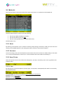
Contents
1
Device Functions and Major Features ......................................................................................................................... 5
1.1 Contents of the Kit................................................................................................................................ 6
2
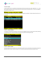
Main Functions ..................................................................................................................................................................... 7
2.1 Witty Timer ........................................................................................................................................... 7
2.1.1
Switching On .............................................................................................................................. 8
2.1.2
Switching Off.............................................................................................................................. 8
2.1.3
Reset .......................................................................................................................................... 8
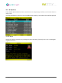
2.2 Photocells ............................................................................................................................................. 9
2.2.1
Mounting Photocells and Reflectors on Tripods ..................................................................... 10
2.2.2
LED Statuses and Colors .......................................................................................................... 11
2.2.3
Paired Photocells ..................................................................................................................... 12
2.3 Radio Transmission............................................................................................................................. 14
2.3.1
Transmission Impulse Duration (Radio Power) ....................................................................... 15
2.4 Elements of the Graphical User Interface .......................................................................................... 18
2.4.1
Virtual Keyboard ...................................................................................................................... 22
2.4.2
The Start (STA) and Stop (STO) Keys ........................................................................................ 23
2.4.3
The Lock Key (LCK) ................................................................................................................... 23
2.4.4
Icons on the Header Bar .......................................................................................................... 24
2.5 Power Supply and Charging ................................................................................................................ 25
2.6 Witty·RFID........................................................................................................................................... 26
2.6.1
Basic operation ........................................................................................................................ 27
2.6.2
LED statuses and colours ......................................................................................................... 28
2.7 Witty·SEM ........................................................................................................................................... 29
3
Quick Setup: how to quickly carry out your first test ........................................................................................ 31
4
Test Types:........................................................................................................................................................................... 36
4.1 Basic .................................................................................................................................................... 36
4.1.1
In Line ...................................................................................................................................... 38
4.1.1.1
Enabling·Witty·SEM as the starting traffic light............................................................... 41
4.1.2
Go & Back ................................................................................................................................ 46
4.1.3
Shuttle with Recovery.............................................................................................................. 47
4.1.3.1
Enabling Witty·SEM ......................................................................................................... 48
4.2 Multistart ............................................................................................................................................ 50
4.2.1
Configuring the Photocells ...................................................................................................... 50
4.3 Counter ............................................................................................................................................... 53
Microgate Srl
P. 2 / 119
4.4 Witty·SEM ........................................................................................................................................... 56
5
4.4.1
Change Direction ..................................................................................................................... 56
4.4.2
Agility ....................................................................................................................................... 59
4.4.2.1
Custom ............................................................................................................................. 60
4.4.2.2
Random............................................................................................................................ 63
4.4.2.3
Random multicolour ........................................................................................................ 64
4.4.2.4
Random multisymbol....................................................................................................... 64
4.4.2.5
Random multisymbol and multicolour ............................................................................ 64
Functions of the Witty Timer ....................................................................................................................................... 65
5.1 Test ..................................................................................................................................................... 66
5.1.1
Simple Test .............................................................................................................................. 67
5.1.1.1
New .................................................................................................................................. 70
5.1.1.2
Delete Event .................................................................................................................... 70
5.1.1.3
Ranking ............................................................................................................................ 71
5.1.1.4
Options ............................................................................................................................ 72
5.1.2
Preconfigured Test .................................................................................................................. 78
5.1.2.1
Load ................................................................................................................................. 79
5.1.2.2
Sprint Start-Stop: timing of a BASIC In-Line Test ............................................................. 79
5.1.2.3
Go & Back: timing of a BASIC Go & Back Test ................................................................. 79
5.1.2.4
Shuttle 5x + 30": timing of a BASIC Shuttle Test.............................................................. 79
5.1.2.5
MultiStart Start-Stop: timing of a MULTISTART Test ....................................................... 81
5.1.2.6
Counter 10x: timing of a COUNTER Test ......................................................................... 86
5.1.3
My Tests................................................................................................................................... 87
5.1.3.1
Load ................................................................................................................................. 87
5.1.3.2
Edit ................................................................................................................................... 87
5.1.3.3
Delete .............................................................................................................................. 87
5.1.3.4
Cancel .............................................................................................................................. 87
5.1.4
Define New Test ...................................................................................................................... 88
5.2 Results ................................................................................................................................................ 91
5.2.1
Show ........................................................................................................................................ 91
5.2.2
Continue .................................................................................................................................. 91
5.2.3
Sort/Filter................................................................................................................................. 91
5.2.3.1
Sort .................................................................................................................................. 91
5.2.3.2
Filter ................................................................................................................................. 92
5.2.3.3
Reset Filter ....................................................................................................................... 93
Microgate Srl
P. 3 / 119
5.2.4
Delete ...................................................................................................................................... 94
5.3 Athletes .............................................................................................................................................. 95
5.3.1
Show ........................................................................................................................................ 95
5.3.2
Sort .......................................................................................................................................... 96
5.3.3
Delete ...................................................................................................................................... 96
5.3.4
Cancel ...................................................................................................................................... 96
5.4 Settings ............................................................................................................................................... 97
5.4.1
Radio ........................................................................................................................................ 98
5.4.1.1
Verify Signal ..................................................................................................................... 98
5.4.1.2
Frequency ........................................................................................................................ 99
5.4.1.3
Photocell Mode ............................................................................................................. 100
5.4.2
Units....................................................................................................................................... 102
5.4.2.1
Measurement Unit: ....................................................................................................... 102
5.4.2.2
Precision ........................................................................................................................ 103
5.4.2.3
Speed ............................................................................................................................. 103
5.4.3
Sound ..................................................................................................................................... 104
5.4.4
Date & Clock .......................................................................................................................... 105
5.4.4.1
Set Date ......................................................................................................................... 105
5.4.4.2
Set Time ......................................................................................................................... 106
5.4.4.3
Date/Time Format ......................................................................................................... 106
5.4.5
Language ................................................................................................................................ 107
5.4.6
Display ................................................................................................................................... 108
5.4.6.1
Brightness ...................................................................................................................... 108
5.4.6.2
Screen Time-Out ............................................................................................................ 109
5.4.7
Peripherals ............................................................................................................................. 110
5.4.8
Witty·SEM .............................................................................................................................. 111
6
Connecting to a PC via Witty Manager ...................................................................................................................112
7
Technical Data ..................................................................................................................................................................113
7.1 Witty Timer ....................................................................................................................................... 113
7.2 Witty GATE Photocell ....................................................................................................................... 114
7.3 Witty·SEM ......................................................................................................................................... 115
7.4 Witty·RFID......................................................................................................................................... 116
Microgate Srl
P. 4 / 119
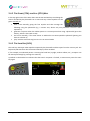
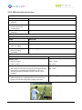
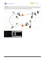
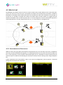
1 DEVICE FUNCTIONS AND MAJOR FEATURES
WITTY is a training timing system ideal for all sports where assessing athletic performance through sprint,
speed, endurance, reaction, shuttle tests, etc. is essential.
Thanks to the timer and photocell-integrated radio system (which do not require special official
authorization), the large color display, the modern user interface featuring icons, and the practical padded
backpack, setup and use is extremely easy and fast.
The system is largely expandable with the possibility to add (single or double) photocells for intermediate
times, accessories such as starting pads, time displaying LED boards, direction indicators, etc.
The kit comes with a free Windows software (which can be downloaded from our website) called Witty
Manager for importing data of performed tests and viewing it in numerical tables and graphs, managing a
complete athlete personal data base (transferring the athlete's picture to the timer for fast identification),
creating customized test types and updating the timer and photocell firmware.
Microgate Srl
P. 5 / 119
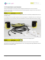
1.1 CONTENTS OF THE KIT
Basic kit (art. £WIT001):
1 Witty timer
2 photocells
2 reflectors
4 tripods
1 backpack
1 wall power supply (with 4 different plugs for all world standards ) + 3 USB cables for charging the
timer and 2 photocells simultaneously
1 USB-PC cable
1 USB memory stick containing Witty manuals and Witty manager software
1 cord
The kit can be expanded purchasing more photocell and reflector pairs with tripod ('Lap Time Kit', art.
£WIT002) for managing more lap times.
Both kits (Basic and Lap Time) are available with a 'Double Photocell' option (see chapter 2.4; the relevant
article codes are £WIT003 and £WIT004)
Microgate Srl
P. 6 / 119
2 MAIN FUNCTIONS
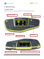
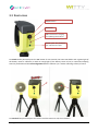
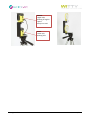
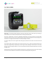
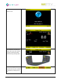
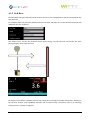
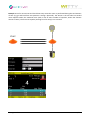
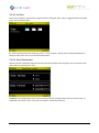
2.1 WITTY TIMER
The figure below shows the main parts of the Witty timer, which will be explained hereafter.
MICROGATE key
LOCK, START and STOP
keys
Confirmation key
(OK)
Numeric keypad
Keypad navigator
Function keys F1 to F4
3.5mm jack for external inputs
Microgate Srl
USB connector for charging and connecting to a PC
P. 7 / 119
2.1.1 SWITCHING ON
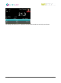
To switch on the Witty timer press the <Microgate> key. After a few seconds required by the boot loader,
a screen is displayed showing the installed firmware version. Press any key to go to the Main Menu.
2.1.2 SWITCHING OFF
From any screen press the <Microgate> key and hold it for 5 seconds.
Another screen prompts to confirm switching off the timer. Press <F1> to confirm or <F4> to cancel.
2.1.3 RESET
If the timer does not respond to any command, press the <Microgate> key and hold it for at least 10 seconds.
When the key is released, the device will be reset and switched off. Press the key again to switch on.
Microgate Srl
P. 8 / 119
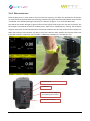
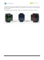
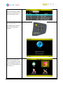
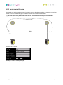
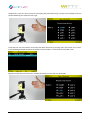
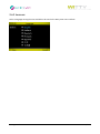
2.2 PHOTOCELLS
ON/OFF button
Status Led
USB connector for charging
and updating the firmware
3.5mm jack for photocell
pair and external inputs
To switch on the photocell press the ON button for one second; the status LED blinks with a green light (if
the battery status is sufficient) or with an orange light (if the battery status is low). A continuous beeping
sound is produced until the correct alignment with the reflector (or a similar reflecting surface) is found.
To switch off the photocell press the button until the LED turns red, then release it.
Microgate Srl
P. 9 / 119
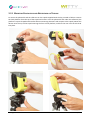
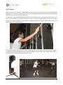
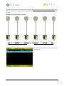
2.2.1 MOUNTING PHOTOCELLS AND REFLECTORS ON TRIPODS
To mount the photocells and the reflectors on the tripods supplied with the kit, proceed as follows: remove
the little platform from the top of the tripod and screw it onto the photocells and under the reflectors (the
platform is square-shaped and therefore allows 4 mounting directions with respect to the tripod). Mount the
devices onto the top of the tripod inserting the front of the platform, and then the rear until the tab clicks
into place.
Microgate Srl
P. 10 / 119
Extend the tripod legs until the required height has been reached (usually the photocell must be interrupted
by the chest of an athlete), and position the photocells and the reflectors at a distance of 1-7 meters (see
also chap. 5.4.1.3 on setting 'Normal' or 'Strong' mode depending on the position).
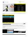
2.2.2 LED STATUSES AND COLORS
PHOTOCELL OFF
STATUS
STATUS LED
Battery charged/empty
Off
External supply
Orange blinking light
Battery charging
External supply
Battery charging
completed
Green steady light
PHOTOCELL ON
STATUS
STATUS LED
NORMAL Mode
Battery charged
Green - Pause
Battery empty
Red - Pause
BOOTLOADER Mode
The photocell has not been switched on pressing the
ON/OFF button but by connecting the USB cable to a PC.
This activates the BootLoader HID and the firmware can be
updated.
CONFIGURATION Mode
Red - Green
Red blinking light
When switching on, the ON/OFF button is pressed for at
least 5 seconds and configuration mode is activated.
Microgate Srl
P. 11 / 119
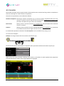
PAIRED PHOTOCELL Mode:
Master photocell (higher serial number)
Battery charged
Green - Pause
Battery empty
Red - Pause
Slave photocell (lower serial number)
Battery charged
Green fast blinking light
Battery empty
Red fast blinking light
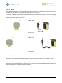
2.2.3 PAIRED PHOTOCELLS
To prevent the photocell being interrupted by an athlete's arm swinging forward, in official competitions or
in any case when measurement must be as accurate as possible, the use of paired photocells is necessary.
This setup ensures that time is measured exactly when the athlete's chest crosses the line, as the impulse
(start/stop/lap, depending on the position) is given only when both photocells are interrupted.
To mount the photocells, screw the C bracket onto the tripod platform, the photocells, and the reflectors, as
shown in the figure (the photocells are mounted at 90° with respect to the C bracket).
Then mount the bracket onto the tripod and connect it with the photocells using the jack-jack cable. The
MASTER photocell is the one with the higher serial number (see chap. 5.4.1.1) and blinks more slowly than
the SLAVE. As the Master photocell transmits the signal to the timer, to ensure a wider aerial range, the latter
should always be mounted on top.
Microgate Srl
P. 12 / 119
Master:
Higher S/N,
blinking at regular
speed.
Always on TOP!
Slave:
Lower S/N,
blinking fast.
Microgate Srl
P. 13 / 119
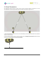
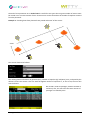
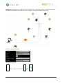
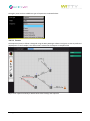
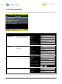
2.3 RADIO TRANSMISSION
t
0m
X 15
MA
MA
X1
50
mt.
The suggested maximum distance to keep in order to prevent reception problems is 150 meters. It is in any
case advisable to check the signal quality with the procedure described in chapter 5.4.1.1.
In case of rainy weather radio transmission can be disturbed by the water drops and therefore the maximum
distance must be reduced.
In order to obtain excellent reception, position the Witty timer at a height of at least 50 cm (without touching
the ground) and do not place it on top of metal objects.
MIN 50 cm
Microgate Srl
P. 14 / 119
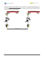
2.3.1 TRANSMISSION IMPULSE DURATION (RADIO POWER)
To increase the reliability of the radio transmission, the data bundles of the photocell impulses are
transferred repeatedly for a set period of 1.2 seconds. This allows to have redundant information when losing
some data bundles and to rebuild the event with absolute precision.
If between two impulses (e.g. start photocell and stop photocell) more than 1.2 seconds elapse, there are of
course no problems whatsoever.
STA Frame
STO Frame
Trasmission of STA for 1,2s
Trasmission of STO for 1,2s
Start
Stop
2,5 sec (> 1.2)
Even if the difference is smaller, the second impulse will still be detected, as it will always have a longer "tail"
than the first one.
STO Frame
STA Frame
Trasmission of STO for 1,2s
Trasmission of STA for 1,2s
Start
Stop
0,8 sec (< 1.2)
Microgate Srl
P. 15 / 119
Problems may arise when intermediate (Lap) times are added and are very close one to another or between
start and stop. Once again it is not necessary that the impulse delta is higher than 1.2 sec, it is enough if the
impulse has a "period" (green line) where there are no other impulses.
L1 Frame
STA Frame
STO Frame
Trasmission of L1 for 1,2s
Trasmission of STA for 1,2s
Start
Trasmission of STO for 1,2s
L1
0,8 sec (< 1.2)
Stop
0,6 sec (< 1.2)
If on the other hand there are several and very close intermediate times, one of these might be "completely"
covered by the previous or following impulses (as in the case of L2 in the figure below), and therefore it would
not be detected.
L2 Frame
L1 Frame
STA Frame
STO Frame
Trasmission of L1 for 1,2s
Trasmission of STA for 1,2s
Start
L1
0,8 sec (< 1.2)
Trasmission of STO for 1,2s
Trasmission of L2 for 1,2s
L2
0,6 sec (< 1.2)
Stop
0,5 sec (< 1.2)
To minimize this problem in case of very fast passages between one photocell and another, the
transmission time can be reduced by one third, i.e. from 1.2 sec to 0.4 sec (see chap. 5.4.1.3.2).
In this case the duration of the impulse transmission is very short and allows a closer setup of the photocells,
but with lower transmission reliability (as fewer redundant bundles are sent). It is advisable to use this mode
(Radio Power = Short) only with the Witty timer close to the photocells and in ideal usage conditions (see
chap. 2.3).
Microgate Srl
P. 16 / 119
In any case, regardless of the impulse distance, if two impulses are perfectly simultaneous (to the
millisecond), one of them will necessarily be lost. For instance, in a multistart test, where the athletes start
while others are on the circuit, if one athlete's stop occurs exactly at the same time as the another athlete's
start, one of the signals will not be detected.
STA Frame at time t0
STO Frame at time t0 (same as STA)
Trasmission of STA for 1,2s
Trasmission of STO for 1,2s
2
1
START
STOP
X sec. (even > 1.2s)
Microgate Srl
P. 17 / 119
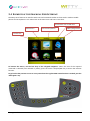
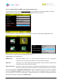
2.4 ELEMENTS OF THE GRAPHICAL USER INTERFACE
The Witty timer features an interface with icons and commands similar to those used in modern mobile
phones and smartphones. Let's take a look at the main icons and how to use them.
Connected to a PC via USB cable
Selected icon
Current menu/section
Battery charge status
Current time
To browse the menus, use the four keys of the <keypad navigator>. When the icon of the required
command is selected (icon outlined in yellow), press the center <Confirm/OK> key to access the relevant
function.
To go back to the previous screen or in any case when the regular BACK or ESC function is needed, pres the
<Microgate> key.
Microgate Srl
P. 18 / 119
When commands are shown in the lower part of the display (inside the yellow portion), they can be selected
using the corresponding <function key>
Dropdown menu
Data table
Selected row
If the Data Tables consist of one or more columns, the rows can be scrolled with the <up> and <down> arrow
keys; the selected row is then highlighted in light blue. Press the <OK> key or one of the <Fn> keys to interact
depending on the context. Pressing the <right> and <left> arrow keys has the same effect as the PgDn and
PgUp keys on a PC, i.e. the list is scrolled down by pages.
In order to open a dropdown list, press the relevant function key (in this case F3 labeled 'Test') or the <up
arrow key>; the dropdown menu opens showing all elements, which can be scrolled using the <up> and
<down> arrow keys, and the required item confirmed with <OK>.
On screens having more than one dropdown menu, use the <up> and <down> arrow keys to select the desired
dropdown menu, then press <OK> to open it. Again use the <up> and <down> arrow keys to scroll the items,
and finally confirm the selected item by pressing <OK>.
Microgate Srl
P. 19 / 119
If you need to type a number, the cursor is automatically positioned inside the field. Use the <numeric
keypad> to enter the required number, and confirm with <F1> (Save) to save the data.
If there are several numeric fields (e.g. date or time input) confirm with <OK> in the various fields to go to
the next one.
As there is no delete (Del/Backspace) key, in case of mistakes just retype the number. Depending on the
context, the fields accept a finite number of digits (e.g. for a date only 2), so the entered data overwrites the
previous one.
e.g. If you want to enter the number 18 in the day field, but you have typed 81, just type 18 again and you
will obtain the following results:
press 1
press 8
For selecting items having exclusive selection buttons (radio buttons), proceed as follows: with the <up>
and <down> arrow keys select the required item, which turns light blue; press <OK> to set the option.
If you want to
change the
language from
Italian (currently
selected option)
to Spanish
Move the cursor
until the item is
highlighted in light
blue and press <OK>.
Remember to SAVE
by pressing <F1>
In case of various radio button groups on the same screen, follow the same steps.
Microgate Srl
P. 20 / 119
If there are control items such as sliders (e.g. for setting the display brightness), move the arrow using the
<right> and <left> keys, and save by pressing <F1>
.
As you might have already noticed from these screens, the <F1> and <F4> keys are often the opposite of
each other and in general it is true that the <F1> always corresponds to Confirm, Save, Yes, whereas <F4> is
used for Cancel, Back, No. Mainly in prompts requiring confirmation it is common to use <F1> = YES and <F4>
= NO.
Microgate Srl
P. 21 / 119
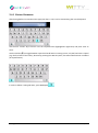
2.4.1 VIRTUAL KEYBOARD
After having defined a customized test type (see chap. 5.1.4) it can be named using the virtual keyboard.
Use the four <arrow> keys to hover over the required letter (highlighted in light blue) and press <OK> to
enter.
Use the shift key () to toggle between capital and small letters. Pressing it once, only the first letter is capital
(e.g. the first letter of the name), whereas by pressing the <OK> key twice, the CAPS-LOCK function is enabled
(all capital letters).
In order to delete a mistyped letter, press BackSpace
Microgate Srl
P. 22 / 119
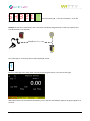
2.4.2 THE START (STA) AND STOP (STO) KEYS
In the top right corner of the timer there are the STA and STO keys simulating the
events recorded by the photocells set as start and stop. These impulses can be
given manually to:
start a test manually giving the first impulse and then manage the
following using the photocells (e.g. a counter test, where only one photocell is used to count
repetitions)
generate a lap time when the athlete passes in a certain point when using 2 photocells (press the
STA key, which is also used as LAP)
end a test manually, if for some reason an athlete has not interrupted the photocell (passing too
close to or below it)
'play' with the timer learning how to use it in manual mode
2.4.3 THE LOCK KEY (LCK)
The Lock key interrupts radio impulse reception by the photocells and the inputs from the 3.5 mm jack. The
keyboard (and therefore also the STA and STO keys) remain enabled.
If, for example, an undesired person is crossing the finish line (a judge, another athlete, etc.), reception can
be interrupted simply by pressing the <LCK> key
A padlock on the header bar indicates that the timer's reception is 'locked'; to reactivate it press the <LCK>
key again.
Microgate Srl
P. 23 / 119
2.4.4 ICONS ON THE HEADER BAR
The top part of the timer (Header bar) displays the current time, as well as the a series of icons relevant to
the current screen:
Battery charged 100%
Battery charged 75%
Battery charged 50%
Battery charged 25%
Battery running low
This indicates that the battery has been charged completely and the timer can be
disconnected from the PC or the wall power supply.
When charging, the battery gets very hot. Disconnect from the power supply and wait
until it has cooled down.
The timer battery is being charged via the PC or wall power supply.
The timer is connected to the PC via USB cable.
The LCK key has been pressed and photocell impulse reception, as well as 3.5 mm jack
reception are disabled.
Microgate Srl
P. 24 / 119
2.5 POWER SUPPLY AND CHARGING
When the device batteries are low they can be recharged simultaneously for as many as 4 devices.
The Witty Timer battery icon level decreases with the decreasing battery charge and turns red when the
battery is almost empty.
Low battery charge on the photocells, Witty·SEM and Witty·RFID is indicated by the RED-PAUSE status LED
(see chap. 2.2.2).
To recharge them use the power supply and connect the plug that is compatible with your national grid
format (Europe, UK, USA, Australia). Connect the USB cables to the power supply and the devices to charge.
The plug icon on the Witty Timer next to the battery icon indicates the charging progress.
On the photocells, Witty·SEM and Witty·RFID (if switched off), the status LED turns orange and blinks.
Both devices can be charged connecting them both to a PC, but charging takes longer (480 mW instead of
800 mW of the wall power supply).
Microgate Srl
P. 25 / 119
2.6 WITTY·RFID
Witty·RFID is an automatic athlete detection system that makes the trainer's work easier by not having to
insert the bib (or shirt number) of the person who is starting in the Witty timer.
The player, supplied with a previously configured bracelet/watch, will simply approach the RFID reader
located near the start and his name, number and photo will automatically appear on the timer display (this
information is managed and downloaded via the Witty Manager software).
An acoustic beep and a series of green LEDs that light up indicate that the data was received and read
correctly.
The washable rubber silicone bracelets have a white space on the "face", where the assigned number can be
written after programming. Programming is done using the Witty Manager software (refer to the Witty
Manager software manager, chapter 3.1.4, for more information) and the same RFID reader that is connected
via USB to a PC.
With Witty·RFID, timing is therefore completely automated, the coach/trainer does not have to do anything
on the timer and can therefore concentrate on the athletes, following them during the test.
Microgate Srl
P. 26 / 119
2.6.1 BASIC OPERATION
Place the Witty timer in start mode in any one of the test types (e.g. the basic test described in the chapter
3). Instead of entering the number of the starting contestant, bring one of the bracelets (which was previously
“numbered” with the Witty Manager software) to a distance of approx. 2 cm. from the Witty·RFID.
The LEDs on the reader will light up green and an acoustic signal confirms that the scan was successful. The
bib number is transmitted via radio to the Witty timer, which sets it immediately for starting. The maximum
distance of the timer and the optimal radio transmission conditions are the same as described in chapter 2.3.
When the proximity sensor detects any object, the 5 front LEDs turn blue, whereas if a bracelet comes near
it that has not been “numbered” yet or if there is a RFID chip reading error, the LEDs turn red.
ON/OFF button
Status Led
USB connector for charging
and updating the firmware
3.5 mm jack, not used
Microgate Srl
P. 27 / 119
2.6.2 LED STATUSES AND COLOURS
FRONT LEDS
STATUS
STATUS LED
Bracelet with bib number
detected
Green
Bracelet without bib
number detected or
scanning error
Red
Non RFID obstacle
detected
Blue
REAR LED
Witty·RFID OFF
STATUS
STATUS LED
Battery charged/empty
Off
External power supply
Orange blinking light
Battery charging
External power supply
Battery charging
completed
Green steady light
Witty·RFID ON
STATUS
STATUS LED
NORMAL mode
Battery charged
Green - Pause
Battery empty
Red - Pause
BOOTLOADER Mode
Witty·RFID has not been switched on pressing the ON/OFF
button but by connecting the USB cable to a PC. This
activates the BootLoader HID and the firmware can be
updated.
CONFIGURATION mode
Red - Green
Red blinking light
When switching on, the ON/OFF button is pressed for at
least 5 seconds and configuration mode is activated
Microgate Srl
P. 28 / 119
2.7 WITTY·SEM
Witty·SEM is an innovative training and rehabilitation system that can be scaled and configured in a simple
and quick manner to meet different needs. Witty·SEM is basically a traffic light integrated with other products
of the Witty family, consisting of a 7x5 LED matrix that is able to manage different contents, such as:
Colours: Red, green and blue
Arrows in different colours
Numbers
Letters
Witty·SEM is centrally controlled by the witty timer via a radio transmission system with a range of up to 150
m, which makes it possible to model the different types of training and analysis in a completely flexible and
reliable manner. Up to 16 traffic lights can be managed from a single Witty console with data acquisition in
real time.
Witty·SEM makes it possible to train and test athletes regarding specific movements depending on the
different types of sports or requirements, targeting their cognitive-motor skills and abilities in order to
prepare them.
Witty·SEM can be used in two different ways:
As a start traffic light and countdown in all available Basic, MultiStart and Counter tests (see chap.
4.1.1.1); usually only one Witty·SEM is used
As a training system for Agility or Direction Change tests, between 1 and 16 can be used (see chap.
4.4)
Microgate Srl
P. 29 / 119
If you have more than one traffic light available, the first thing to do is to make sure that each has been
configured with a different address (from A to R). The address can be seen directly on the traffic light right
after it is turned on.
It is configured using the Witty Manager software (see the Software manual in chapter 3.4 for details)
Microgate Srl
P. 30 / 119
3 QUICK SETUP: HOW TO QUICKLY CARRY OUT YOUR FIRST TEST
In a few steps we will show you how to carry out your first test:
Switch the Witty Timer on
(chap. 2.1.1).
Mount the photocells onto the
tripods and turn them on
(chap. 2.2.1); position the start
and finish photocells at a
certain distance.
1
START
STOP
From the main menu select
Test and then Test Base.
Microgate Srl
P. 31 / 119
In the top left corner the
athlete's number as well as the
athlete's trial number are
displayed.
The athlete starts and as soon
as he crosses the first photocell
timing begins.
1
START
Microgate Srl
STOP
P. 32 / 119
When the athlete interrupts
the finish photocell, timing is
stopped and a line is generated
in the table at the bottom of
the screen.
After 3 seconds timing
continues, because as default
all photocells are set as start
photocells and do not receive a
stop impulse, but this does not
affect the performance of a
test.
1
START
STOP
Press <F1> under 'NEW' for
another athlete (in this case
bib #2).
2
START
Microgate Srl
STOP
P. 33 / 119
Press <F1> to confirm another
athlete's start.
If the athlete has another bib
number just enter the number
using the numerical keypad
and confirm by pressing <OK>.
The <F3> Rankings button can
be pressed at any time to show
the temporary ranking of the
test.
Microgate Srl
P. 34 / 119
Pressing the <Microgate> key
(which can always be used for
Back/Esc) or <F4> takes you
back to the timing screen.
When all athletes have finished
their test, press the
<Microgate> key to exit the
Test menu (confirmation
required)
Press the <Microgate> key
again to return to the main
menu. It is possible to review
the test (ranking), continue or
delete it from the Result menu
(see chap. 5.2)
Microgate Srl
P. 35 / 119
When the test session has
been completed, switch off the
timer (chap. 2.1.2) and the
photocells (chap. 2.2.1)
4 TEST TYPES:
Witty can handle various test types (sprint, shuttle, go & back, athlete groups, repetitions, etc.), which are
described below.
Tests are divided into the following main types:
Icon
Name
Description
BASIC
Tests for in-line timing of single athletes (one after the other) in laps or circuits
(sprint, shuttle, go & back, endurance, etc.).
MULTISTART
Test for timing several athletes (max. 3) simultaneously.
COUNTER
Test for timing or counting repeated actions.
WITTY·SEM
Test for agility and change direction performed with Witty·SEM
The various options available for each main type are explained below.
4.1 BASIC
The basic tests are divided into different sub-types:
For every type it is necessary to define when and how the test is completed (End of Test parameter).
Possible options are:
Microgate Srl
P. 36 / 119
Number of Impulses:
Choosing a finite number of impulses (e.g. 5) the test will be completed
when the timer receives a number of events equal to the set parameter
except for the first Start event. Leaving the parameter on '0'
(undefined), the test never ends and the operator will decide when
another athlete begins the test.
End of Time
Setting a time in minutes:seconds, the test will finish when the set
amount of time is reached.
No. of Impulses or End of Time
Setting both parameters, the test ends when the first of the two
conditions is reached.
Microgate Srl
P. 37 / 119
4.1.1 IN LINE
Basic / In Line tests are the simplest kind of tests and allow, for example, sprint timing over a certain distance.
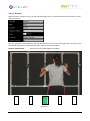
Example 1a. To time a sprint test over 30 meters with Start and Stop it is enough to set the End of Test with
'Number of Impulses' equal to 1 (please note that the Start Impulse must never be counted).
START
STOP
30 mt
Example 1b. If you want to add one or more lap times, just increase the value of Number of Impulses.
START
LAP1
LAP2
STOP
3 IMPULSES
Microgate Srl
P. 38 / 119
The End of Test parameter set to 'End of Time' is useful for test types where a given number of actions must
be carried out in a certain amount of time. These actions can be counted via the number of impulses received
from the photocell.
Example 2: Checking how often photocells are passed within 30" of this course:
START
The test will finished as follows:
The ranking shows information by position (Pos), number of impulses (#), bib (Num), time, and possibly the
athlete's name. The winner is the one with the highest number of impulses or, in case of tie, the one who
was the fastest.
Bib 14 and 1 made six passages, whereas number 8
and 9 only five; the ones with the same amount of
passages are ranked by time.
Microgate Srl
P. 39 / 119
Example 3. If in a test an athlete must complete a circuit within 20" and there is only one start and stop, the
end of test can be set as 'Number of Impulses or End of Time'; if the athlete manages to perform the test,
his time will be saved, otherwise the timer is stopped.
START
Microgate Srl
STOP
P. 40 / 119
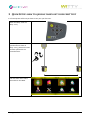
4.1.1.1 ENABLING·WITTY·SEM AS THE STARTING TRAFFIC LIGHT
The last parameter that is found in every type of test is the possibility to use the Witty·SEM as a starting
traffic light with a predefined countdown that shows athletes when they can start.
Once this selection has been enabled, press <F3> Options and then select the Witty·SEM Options icon
The next screen is used to select the following parameters:
“Type of start” it can be defined as:
Without start
Witty·SEM displays every "n" minutes:seconds (defined with the “Countdown
repetition timer” parameter) the sequence of the selected countdown.
With start
Like above, but a radio START impulse is generated at the end of the countdown and
the timer starts to time the current athlete.
With random start
Like above, but the start impulse is not generated immediately after the countdown,
but after a random period of time that does not exceed the “Random time” parameter
The second parameter “Countdown repetition time” (mm:ss) indicates how often the cycle is repeated,
whereas “Countdown Template” makes it possible to select one of the 3 predefined types of countdowns
(3, 5, 10 seconds). In the case of “Start type” or “With random start” it is possible to indicate within what
period of time the start is generated (“Random time”)
Microgate Srl
P. 41 / 119
Here are a few examples:
Example 1: Start every 45 seconds, with a 5 second countdown, without start generation (as it is taken by
the first photocell)
START
STOP
The traffic light is in stand-by with its index displayed in blue
A
The first traffic light start takes place manually by pressing the button <F1> Start Traffic Light
Witty·SEM carries out the selected countdown (5 sec.) and then immediately displays the green signal for 5
seconds.
Microgate Srl
P. 42 / 119
54321▓
…wait 35 seconds (45 – 5 for the countdown – 5 for the
green) and restart
Example 2: Start every 30 seconds, with a 3 second countdown and generation of the start impulse (the
start photocells is not required)
Should be < Trepet. sec.
STOP
The traffic light is in stand-by with its index displayed in blue
A
The first traffic light start takes place manually by pressing the button <F1> Start Traffic Light
Witty·SEM carries out the selected countdown (5 sec.) and then immediately displays the green signal for 5
seconds.
Microgate Srl
P. 43 / 119
321▓
As soon as green appears, Witty·SEM launches a start impulse via
radio and starts the timer
…afterwards, it waits 22 seconds (30 – 3 for the countdown – 5 for green) and restarts the cycle.
ATTENTION: If within the 30 seconds defined in the countdown repetition time the current athlete has not
yet arrived, the next automatic START provided by Witty·SEM will be interpreted as the STOP of the previous
athlete. Therefore, repeat a repetition time that is greater than the test time (with a certain safety margin).
Microgate Srl
P. 44 / 119
Example 3: Start every minute, with a 10 second countdown, with generation of a random start from 0 to 7
seconds after the end of the countdown. In this case, the type of test is MultiStart (see chap4.2) and the
athletes go to the start after scanning their bracelet with Witty·RFID (see chap 2.6)
3
2
START
1
STOP
Microgate Srl
P. 45 / 119
4.1.2 GO & BACK
The Go & Back test type is basically similar to the In-Line test, but is designed for a specific test type with only
one photocell.
For example: place the photocell (which will be used as Start and Stop) at a certain distance from the wall
and define the test as follows:
The athlete starts, crosses the photocell (which starts timing), touches the wall and crosses the same
photocell again, which stops the time.
Of course it is possible to complete various 'laps' simply by increasing the number of impulses. Similarly to
the previous chapter several go&back exercises can be created with a maximum time or by matching
maximum time / number of impulses.
Microgate Srl
P. 46 / 119
4.1.3 SHUTTLE WITH RECOVERY
The Shuttle test (with or without recovery) allows to execute shuttle tests, where an exercise is carried out a
certain amount of times with a given number of seconds for recovery between them.
e.g. 50-meter sprint to be performed 3 times with 20" recovery between one sprint and the other.
Recovery in 20"
RUN
3X
START
STOP
The test is set as follows:
See chap. 5.1.2.4 for a timing example.
Microgate Srl
P. 47 / 119
4.1.3.1 ENABLING WITTY·SEM
If Witty·SEM is enabled to be used as a start traffic light, there will be two additional options for Type of start
“From the last impulse”, start the selected countdown (3s,5s,10s) after the athlete triggered the last impulse
of each individual repetition (the stop photocell in the figure). Always remember to press <F1> Start Sem
light at the beginning of the test.
3...2...1
Recovery in 20"
RUN
3X
START
Microgate Srl
STOP
P. 48 / 119
“From the last impulse with start”, when pressing Start traffic light and after the selected countdown
(3s,5s,10s), a start impulse is transmitted to the timer. This is useful when only one photocell is available that
is used for the stop
3...2...1...START
Recovery in 20"
RUN
3X
STOP
Microgate Srl
P. 49 / 119
4.2 MULTISTART
The MultiStart test allows to time circuits or courses carried out by several athletes at the same time (max.
3) from the start line to the finish line. The athletes must NOT start simultaneously (otherwise it would be
impossible to associate events to bibs) but must start one after the other and in sequence. Even though, as
we will see, it is possible to manage cases where one athlete passes another athlete, we suggest that you
distance the athlete starts in order to prevent this. If a certain sequence of events connected to impulses is
maintained (athlete 1 start-lap, athlete2 start-lap, etc.), it is much easier to manage the test.
3
2
P1
LA
START
1
P2
LA
STOP
4.2.1 CONFIGURING THE PHOTOCELLS
While for other test types (Basic and Counter) the photocells are set in the same way (start), in MultiStart
tests they must be identified and assigned (i.e. set which photocells are start, which are stop and which are
lap-n). This assignment can be carried out when defining the test (it is advisable to mark the photocells with
a piece of tape or a label for the following test sessions) or directly from the timing screen using the Options
key.
Create a MultiStart test as described in chap. 5.1.4. From test configuration, click on Options > Photocell
Config, where an empty list is displayed:
Microgate Srl
P. 50 / 119
Assignment is very easy and consists of interrupting the photocell (having a unique serial number) with one
hand and defining the required event type:
Scroll with the <up> and <down> arrow keys and select the event by pressing <OK>, then select <F1> to save.
In the following example the photocell with the serial number 1 is associated to the START event.
Repeat the operation with the other available photocells (at least the stop photocell):
Microgate Srl
P. 51 / 119
after which the situation will be the following (with more or less LAP photocells depending on how many are
available):
Press <F1> to save the configuration! (By pressing <F4> or <Microgate> the previous screen is closed without
saving, thus all entered data will be lost).
To change the event type associated to a photocell, go to the line (light blue color) of the required photocell
and press <F3>. Similarly to the first photocell, choose the event type and save by pressing <F1>.
It is not possible to delete a single assignment, but only to reset the configuration (<F2> key) to begin a new
assignment.
By closing the Test configuration screen it is possible to set a Max Time for completing the circuit/course. The
field can be left undefined or you can set a value in minutes:seconds.
Microgate Srl
P. 52 / 119
4.3 COUNTER
The Counter test type counts a given number of actions/exercises or checks how long it takes to complete an
exercise consisting of a certain number of repetitions.
The End of Test parameter can be defined as follows:
Number of Impulses: Choosing a number of impulses (e.g. 5) the test will be completed when the timer
receives a number of events equal to the entered value, including the first Start event
(not like in the Basic test type, where it is excluded).
End of Time
Setting a time in minutes:seconds, the complete test will finish when the set amount
of time is reached.
Timeout
Setting a time in minutes:seconds, the test ends when the 'repetitions' are carried out
in an amount of time that is higher than the one set.
It is furthermore possible to indicate if the First Impulse is to be included in the timing or not.
Let's see some examples:
Example 1. Timing of how much time it takes to do 10 push-ups.
Set the test with End of Test=Number of Impulses and as parameter the desired number of push-ups:
While timing, the main parameter showing is the counter. In the table, for each repetition the progressive
time and the amount of time of the single repetition is displayed.
Microgate Srl
P. 53 / 119
Example 2. Test for one minute and check how many times the action is performed during the total amount
of time (e.g. go and back from two positions crossing a photocell). The winner is the one who has totaled
more impulses within the maximum time (and in case of same number of impulses, within the shortest
amount of time). The first start impulse (starting from far away) is not counted.
START
Microgate Srl
P. 54 / 119
Example 3. A certain repetitive action must be carried out within 30 seconds (e.g. slalom through cones or a
series of jumps). If the repetition takes longer than the set time, the test is stopped. The winner is the athlete
performing the highest number of repetitions.
Microgate Srl
P. 55 / 119
4.4 WITTY·SEM
There are two categories of "Witty·SEM” tests:
4.4.1 CHANGE DIRECTION
The Witty·SEM/Change Direction type of tests are used to perform exercises in which the traffic light has the
athlete change direction randomly (right, left, forwards, backwards) using the arrow symbols.
Example 1: this could be a variant of the classic T-test, where the athlete starts off, crosses a Start photocell,
runs a few metres and the traffic light indicates (randomly) to sprint to the right or to the left;
Delay Time
STOP
STOP
START
Microgate Srl
P. 56 / 119
To carry out this type of exercise, set the test as follows
Delay:
Insert the delay in tenths of a second, after which Witty·SEM turns on
the direction change arrow. The parameter is set, calculating approx.
the time the athlete takes from the last impulse before the traffic light
to the direction change point.
Number of impulses
Number of impulses after which Witty·SEM displays the arrow. In
example 1 it is set to 1 (start photocell before the traffic light); in
example 2 below, it is set to 2 (start + lap1).
Direction
This indicates the directions Witty·SEM displays; the possible selections
are left/right, left/right/forwards, left/right/forwards/backwards
The sequence takes place as follows:
Witty·SEM off– start impulse – half a second wait (5 tenths) – appearance of the right or left arrow – stop
impulse – Witty·SEM indicates its index (A,B,C). Pressing <F1> New, the sequence restarts.
Microgate Srl
P. 57 / 119
Example 2: The athlete starts, triggers the start photocell, does a lap, after n tenths of a delay, Witty·SEM
indicates to the athlete to go to the right, left or straight. The stop photocells stop the time.
The test is defined as follows:
The sequence will be:
– Start – Lap1 – 1 sec. pause -
Microgate Srl
> A
- Stop -
P. 58 / 119
4.4.2 AGILITY
With this type of test, the Witty + Witty·SEM system becomes a tool to have the athlete perform speed &
agility exercises, where the objective is to “turn off” the traffic light by approaching the proximity sensor with
a hand (or foot, a racquet or other body parts).
It is obvious that multiple Witty·SEM traffic lights must be used that, after receiving the test parameters, will
turn on/off according to a sequence pre-set by the user or randomly depending on the mode. The traffic
lights can be positioned differently (on tripods, on magnetic supports, on suction cups on the ground, etc.)
depending on the selected exercise.
If you do not want the athlete to come near the traffic light but rather trigger the passage through a “gate”,
it is possible to combine a photocells with a traffic light using a C-bracket and connecting them to a cable (the
same way as with a double photocell, see chap. 2.2.3).
Microgate Srl
P. 59 / 119
The Agility tests can have a different type of sequence as indicated below:
4.4.2.1 CUSTOM
The Sequence (route) to follow is designed using the Witty Manager software and given a name as preferred
(MySequence in the example). The same name is selected in the Sequence Template field.
Refer to the software manual for details about how to design the sequence.
Microgate Srl
P. 60 / 119
The following fields are the same for all types of sequences:
Sequence template:
Select one of the customised templates created with Witty Manager
Delay:
Delay in tenths of a second between the turning off of a traffic light and the
turning on of the next one
End of test
This indicates the way the test ends, it can be
Number of Impulses:
Choosing a finite number of impulses (e.g. 5) the test will be completed
when the timer receives a number of events (traffic light "off" operations)
equal to the set parameter. The parameter is calculated automatically in
the case of customised sequences.
End of Time
Setting a time in minutes:seconds, the test will finish when the set
amount of time is reached.
No. of Impulses or End of Time
Setting both parameters, the test ends when the first of the two
conditions is reached.
Pressing the key <F3> Options and selecting the Witty·SEM icon makes it possible to select the colour, type
of symbol and the symbol/character/number to follow. The default setting is always the green block
(rectangle), but it is possible to have an athlete follow a letter (lower case or upper case) or a number with
one of the three available colours
Microgate Srl
P. 61 / 119
Catch the colour:
Select one of the 3 available colours; green, red, blue
Catch the symbol from:
Numbers and characters (▓, 0…9, a…e)
Characters only (▓, A…O)
Catch the symbol
The block, the letter or the number depending on the selected set
The test starts with a 3 second countdown and then turns on the first traffic light that the athlete must turn
off.
As soon as it is turned off via the proximity sensor or by obscuring the connected photocell, it turns on the
next one (with a possible set delay of n tenths of a second).
The timer detects the OFF condition via the intermediate times
If a route was created that also indicated the distances, also the speeds are displayed.
It is very important to adjust the proximity sensor threshold in accordance with how the test should be carried
out; if the athlete must get very close to the traffic light (almost touching it) set the threshold to "close",
otherwise "average" or "distant" should be sufficient (see chap. 5.4.8)
Microgate Srl
P. 62 / 119
4.4.2.2 RANDOM
With this type of sequence, only one of the N traffic lights turns on with the selected symbol/colour, all the
others remain off.
The only parameter that is different than the previous one is how many traffic lights that are used (in the
customised sequences, it is automatically taken from the selected template)
Number of Witty·SEM:
Indicate how many Witty·SEM are available
▓
Catch this !
Microgate Srl
P. 63 / 119
4.4.2.3 RANDOM MULTICOLOUR
The colour to be followed is defined (e.g. ▓ red); the other traffic lights display nothing, or the same symbol
but in a different colour
▓
▓
▓
▓
Catch this !
4.4.2.4 RANDOM MULTISYMBOL
The symbol to be followed is defined (e.g. F blue); the other traffic lights display nothing, or other symbols in
the same set, but always in the same colour
E
A
F
C
Catch this !
4.4.2.5 RANDOM MULTISYMBOL AND MULTICOLOUR
The symbol and colour to be followed is defined (e.g. 4 green); the other traffic lights will display nothing or
other combinations of symbols and colours different than the one selected.
d
4
4
e
Catch this !
Microgate Srl
P. 64 / 119
5 FUNCTIONS OF THE WITTY TIMER
The main menu displays the four macro areas, which will be described in the following chapters.
Microgate Srl
P. 65 / 119
5.1 TEST
The Test section, the heart of the Witty software, allows to perform timing actions and define particular
customized test types (this can also be carried out from the Witty Manager PC software).
Microgate Srl
P. 66 / 119
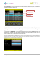
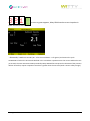
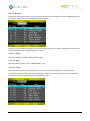
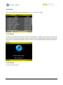
5.1.1 SIMPLE TEST
The Simple Test is simply a 'Basic / In Line' test (see chap. 4.1.1) with a defined number of lap times (from 0
to n).
The elements displayed on the screen when timing are as follows:
Bib Number
Trial Number
Athlete Name
Athlete Picture
Running Time
Last Lap
Lap Time/Speed
Table
Split
Lap
Function Keys
In order to familiarize with the Witty timer functions, substitute the impulses received from the photocells
by pressing the Start and Stop keys on the left side of the timer (lap times are simulated by pressing the
<STA> key).
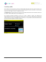
Press the Simple Test icon in the Test menu and access the timing function. If no start list and athlete
names/pictures have been set with the WittyManager software, the displayed screen will appear as follows:
Now the athlete with bib number 1 can begin
Trial number 1.
If another athlete is in starting position, enter his
bib number using the numerical keypad and
press <OK>.
Microgate Srl
P. 67 / 119
Now have the athlete cross the Start photocell (or press the <STA> key) and timing will begin. When the
photocell is interrupted for the second time, timing is stopped and the first line containing time and lap time
(which of course are the same) appear in the table. After 3 seconds timing is resumed (as in this test type an
undefined number of laps is possible and the photocells always give a Start/Lap impulse and never a Stop
impulse).
Press <F1> New and the system asks, if you want to continue with another athlete. If so, the following athlete
is suggested (bib no.+1 or, if a start list has been provided, the next one on the list).
If you enter the bib number of an athlete who has already carried out a trial, he will be accepted but the Trial
number will be increased by one.
Microgate Srl
P. 68 / 119
If there is more than one photocell for lap timing, the lap times are saved and displayed as a table which can
be scrolled using the <up> and <down> arrows. The scrollbar on the right indicates that there are more lap
times to scroll through.
The Time column (SPLIT) is the running time beginning from the start, whereas the lap time (LAP) is the time
of one single lap.
START
L1
LAP1
L2
LAP2
L3
LAP3
STOP
LAP4
SPLIT1
SPLIT2
SPLIT3
SPLIT4 (TOTAL TIME)
Microgate Srl
P. 69 / 119
By pressing <Microgate> and confirming, the menu is closed.
If you want to begin a New Test, select the Simple Test icon again (or one of the other customized or
predefined test types), whereas if you want to continue the test that you have just closed, use Continue in
the Results menu, as described in chap. 5.2.
Now let's take a look at the various options that can be selected with the function keys:
5.1.1.1 NEW
The next athlete (or the next on the start list) is suggested but confirmation is needed. A number may be
forced by entering the digits and pressing <OK>.
5.1.1.2 DELETE EVENT
If an external element has interrupted a photocell causing an undesired impulse, the LAST EVENT (impulse)
which has been received can be deleted by pressing <F2> Delete Event and confirmed by selecting Yes.
WARNING: The deleted item is always the last one, not the one highlighted in light blue in the table.
Microgate Srl
P. 70 / 119
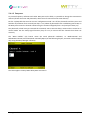
5.1.1.3 RANKING
Display the raking of the current Trial (or of a given trial). A certain athlete's test can be displayed and the
list can be sorted by time or bib number (to find an athlete).
Use the <up> and <down> arrow keys to scroll the ranking and <F1> (or <OK>) to display the selected test
(in this example the test of athlete number 1, Rossi).
5.1.1.3.1 View
View the selected test with all lap times (if present).
5.1.1.3.2 Sort
Sort the ranking by Time -<F1>- or Number (Bib) -<F2>5.1.1.3.3 Trial
Place the cursor on the 'Trial' dropdown menu in order to view a trial ranking or all trials together.
In this case the bib column (Num) has the format X.Y, where X is the bib and Y the trial (in the following
example the athlete with the best time is athlete #1 in trial 1).
Microgate Srl
P. 71 / 119
5.1.1.3.4 Cancel
Press <F4> Cancel to return to the timing screen.
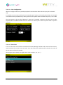
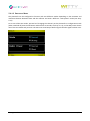
5.1.1.4 OPTIONS
Recall a menu for configuring lines, speed bases, and start lists:
Microgate Srl
P. 72 / 119
5.1.1.4.1 Line Configuration
Allows to configure the lines of possible peripherals connected via cable with the input jack on the back
side.
It is possible to set the start and finish line to 'Normally Open' (NA) or to 'Normally Closed' (NC). For example
a connected contact pad (Start Pad), which gives the start impulse when the athlete steps off it, is set to NC.
The start timeout is the so-called 'dead time'; setting it, for example, to 200 ms, after the start no other
impulses will be considered within the first 2 tenths of a minute (this is useful to prevent false or spurious
contacts).
5.1.1.4.2 Start Lists
If one or more Start Lists have been created with the Witty Manager software and transferred to the timer,
with this option they can be chosen and used. From that moment the athletes will be placed in the order of
the list and not of their bib number.
Choosing this option (None), the regular start order is used (1, 2, 3, 4, 5...).
Microgate Srl
P. 73 / 119
5.1.1.4.3 Multi Base Speed
This function (as well as the single Base) allows to define the distances between the photocells in order to
determine the speed in the various trial laps. If the distances have been set in the time/lap table, the speed
will be displayed (expressed in the chosen unit, see chap. 5.4.2.3).
The indication 'multi' does not mean that more than one base must be set. A classic sprint of n meters without
lap can (and must) also be timed with this option. Let's see some examples:
30-Meter Sprint with Only One Start And Stop
START
STOP
30 mt
Set the distance (in meters/centimeters or feet/inches depending on the settings of the measuring unit)
between start and stop and press <F1> Save.
Microgate Srl
P. 74 / 119
60-Meter Sprint with Lap Time after 10 Meters and 30 Meters.
START
L1
LAP1 = 10 mt.
L2
STOP
LAP2 = 20 mt.
LAP3 = 30 mt
START-STOP = 60 mt
Enter the Start-Stop Base as in the previous
example.
Then press <F3> to add the Lap1 Base and enter the
distance.
Do the same for the Lap2 and Lap3 bases.
Remember to SAVE by pressing <F1>.
You can move around in the table to change the
distance of a previously added Base.
To delete one or more bases, press <F2> to reset
the list and enter new data.
Microgate Srl
P. 75 / 119
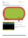
5.1.1.4.4 Single Base Speed
This option must be used to set a Base with a single distance to be completed many times. A classic
example is a 400-meter track, with a lap time and speed measured at every lap.
Enter the Base Lap by typing the distance.
Remember to SAVE by pressing <F1>.
You can easily change the distance by typing it
again or pressing <F2> to reset it and then enter
the new data.
Microgate Srl
P. 76 / 119
The Speed Single Base can be used also when there are several lap time measures at equal distances. In this
case it is not necessary to define a multi base with equal distances, but it is enough to define the single base
once, e.g.
50-Meter Sprint with 10-Meter Lap Time.
START
L1
LAP1 = 10 mt.
L2
LAP2 = 10 mt.
L3
LAP3 = 10 mt.
L4
LAP4 = 10 mt.
STOP
LAP5 = 10 mt.
START-STOP = 50 mt
Enter the Base Lap at 10 meters and save by
pressing <F1>.
Microgate Srl
P. 77 / 119
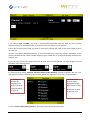
5.1.2 PRECONFIGURED TEST
On this screen there are 4 of the most common test types that Microgate has made available as examples
The tests are defined as follows:
Test Name
Description
Sprint Start-Stop
Sprint test with start and
stop without lap times
Go & Back
Go and back test with 1
photocell
Shuttle 5x + 30"
Shuttle test with 5
repetitions and 30" recovery
Defined as
MultiStart Start-Stop Generic group test
Microgate Srl
P. 78 / 119
Counter 10x
Test with 10 repetitions
5.1.2.1 LOAD
To begin a timing session of the desired type, select the line using the <up> and <down> arrow keys and press
<F1> Load (or the <OK> key).
Now, thanks to these preconfigured tests, let's see an example for every test type:
5.1.2.2 SPRINT START-STOP: TIMING OF A BASIC IN-LINE TEST
The Test Base is this type of test; please refer to chap. 5.1.1 for further information.
5.1.2.3 GO & BACK: TIMING OF A BASIC GO & BACK TEST
The Go & Back test is also basically the same as an In-Line test; please refer to the latter for further
information.
5.1.2.4 SHUTTLE 5X + 30": TIMING OF A BASIC SHUTTLE TEST
During the first sprint, the timer shows information as for an In-Line test; after crossing the stop photocell, a
countdown starts for the amount of time set as recovery time:
When the athlete starts again for the second sprint, the advance or delay (signaled by an intermittent beep)
is calculated with respect to the recovery time; these times are highlighted on the data table with the letter
R (Recovery). In the example below the athlete has begun the second sprint with an advance of -1.4, and the
third with a delay of +1.6.
Microgate Srl
P. 79 / 119
The ranking sums the times of n repetitions and does NOT consider the start delays or advances.
Microgate Srl
P. 80 / 119
5.1.2.5 MULTISTART START-STOP: TIMING OF A MULTISTART TEST
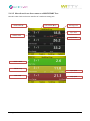
Now let's take a look at the user interface of a multistart timing test.
Bib Number (#)
Trial Number (Run)
Running Time
Lap n Time
Athlete Name
Lap Number
Green = Start
Yellow = Lap
Lap1 speed
Red = Stop
Microgate Srl
Stop speed
P. 81 / 119
At the beginning of the test, athlete #1 is ready to start (or the
first of the Start List, if one has been set).
If you want to force another bib number, just type it using the
numerical keypad and confirm by pressing <OK>.
If the photocells have not been configured in the test
definition (see chap. 5.1.4), it must be done now. Press <F4>
to access this option or other available options.
Athlete #1 starts, his sector becomes green for 5 seconds and
then scrolls down to get ready for the next athlete.
Similarly, when number #3 starts, the first two athletes scroll
down. If a LAP impulse is received, the sector of the athlete
generating it turns yellow.
Microgate Srl
P. 82 / 119
When the athletes cross the finish line (stop impulse), the final
time is showed in red for 5 seconds and then disappears to
show the next athlete starting.
If an athlete passes the athlete in front of him, the athletes
can be changed on the fly, while they are running, using the
<up> and <down> arrow keys.
For example, athlete #1 started before #2... after approx. 40
seconds, passing takes place and the impulses must be
assigned to #2. Just press <down> to replace the athletes
(press <up> to replace them again).
It is also possible to delete undesired events or consider an
athlete as 'Not Arrived'; press <F1> Edit to access the following
options:
<F1> Delete STArt
<F2> Delete STOp
<F3> Delete LAP
<F4> NA (Not Arrived)
Microgate Srl
P. 83 / 119
Pressing one of the first 2 function keys, the last event of that
type received (start or stop) is deleted. Confirmation is
required and if you press Yes, the line status is reset to the
previous status (if you delete a Start, the athlete is reset to the
start, but if a Stop is deleted, his time starts running again).
By pressing <F3> you can delete a Lap. You can choose to
delete the last received Lap event or be more precise and
indicate the Lap number and the athlete that it was assigned
to.
Press <F1> Delete Last to delete the last Lap (confirmation
required)
Press <F3> Delete Number and enter the Lap and Bib Number
to delete a specific event (in the example Lap 1 of athlete #14
will be deleted).
If you want to 'disqualify' an athlete (or consider him 'not
arrived'), just press <F4> NA in the Edit sub menu. If there are
several simultaneous athletes, you will need to confirm the
one to be deleted. Using the keys F1 to F4 select the bib of
the athlete to remove (in the example #2 ) .
Instead of the arrival time the writing DNF (Did not finish) is
displayed.
Microgate Srl
P. 84 / 119
The writing DNF is also displayed if in the Multistart test
definition a maximum time has been set for finishing the
execution and one of the athletes has exceeded that time.
The times of two athletes can be replaced using <F2>Replace.
Enter the bibs of the athletes we want to replace. All times of
the first athlete (#10) will be assigned to the second one (#13).
Press <F3> Rankings to view the ranking.
Microgate Srl
P. 85 / 119
5.1.2.6 COUNTER 10X: TIMING OF A COUNTER TEST
The test starts when the first impulse is received and in the center the counter increases with every event.
After 10 impulses (excluding start), the test is finished.
The options available with keys <F1> to <F4> are similar to the ones for the Basic Test.
Microgate Srl
P. 86 / 119
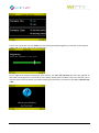
5.1.3 MY TESTS
In this screen you will find all customized test types defined by the user (directly on the timer or via the Witty
Manager software).
The icon in front of the name indicates the test type (Basic, Multistart, Counter).
5.1.3.1 LOAD
To begin a timing session of the desired type, select the line using the <up> and <down> arrow keys and press
<F1> Load (or the <OK> key).
5.1.3.2 EDIT
Allows to display the general settings of the test type or edit the Options (configuration of lines, speed bases
and, for multistart tests, photocell configuration). Editing of definition parameters is not available, because
if trials of that type were already carried out, it would not be possible to compare them with the new ones.
5.1.3.3 DELETE
Delete the customized test type. Confirmation is required:
NB: Only the test definition is deleted; any possible trials of that type will NOT be deleted.
5.1.3.4 CANCEL
Exit the previous menu.
Microgate Srl
P. 87 / 119
5.1.4 DEFINE NEW TEST
With this option new customized test types can be defined. Please refer to chap. 4 for further information
on the various available test types and relevant options.
Choose the test macro type by pressing <OK> to open the dropdown menu, scroll up or down with <up> or
<down>, and confirm with <OK>.
Depending on the chosen options, additional dropdown menus or numerical fields to be completed with the
necessary information are displayed.
Microgate Srl
P. 88 / 119
By pressing <F3> Options you can configure Lines and Speed Bases as explained in chap. 5.1.1.4. For
MultiStart tests a menu item for configuring photocells will also be displayed.
Press <F4> Back to go back to the test definition.
Press <F1> to save the Test definition. A consistency check is carried out on the data and if any dropdown
menu or field has not been filled, an error mask will warn the user. By pressing <F4> (after having confirmed)
the screen is closed without saving.
If all fields have been completed correctly, after pressing Save the user will be asked to name the customized
test definition.
A name such as MyTestTYPEnn is suggested. For example, MyTestBasic1, MyTestCounter2, etc.
If the name is okay, confirm again by pressing <F1> Save, whereas if you want to change it to something
easier to remember and more significant (recommended), use the virtual keyboard (remember that to make
this easier it is possible to create definitions using the Witty Manager software and then transfer them via
USB to the timer).
If you choose a name which has already been used in a previous test definition, the user will be prompted to
choose another one (this happens also if you have deleted the previous definition but there are trials
associated to that definition.
Please refer to chap. 2.4.1 for information on how to use the virtual keyboard.
Microgate Srl
P. 89 / 119
After having saved the test with <F1>, it will be displayed with the same name in the list named 'My Test'
(chap. 5.1.2).
Microgate Srl
P. 90 / 119
5.2 RESULTS
This function allows to show the results of the tests carried out or to continue an interrupted trial.
The data table displays 3 columns with the following:
the test type (Basic, MultiStart, Counter)
the date and time of the test start
the test name (predefined or customized basic test)
Possible Options are:
5.2.1 SHOW
By selecting a test with the <up> or <down> arrow keys and pressing <F1>Show (or <OK>) you access the trial
ranking. The available Options in the ranking are similar to those in the previous chapters.
5.2.2 CONTINUE
Access the timing screen of the selected test and continue the test from the last athlete ready to start (bib
n+1, or the one selected from a start list, or the first athlete with trial number increased by 1).
5.2.3 SORT/FILTER
Select this option to access one of the two sub-options ( <F1>Sort, <F2>Filter); press <F4> to go back to the
previous menu.
5.2.3.1 SORT
By selecting one of the three Options (<F1>By Type, <F2> By Date, <F3>By Name) the result list is sorted by
the selected column.
Sorting by Type the order is the following: Basic, MultiStart, and Counter.
By Date sorting is descending (most recent tests are at the top of the list).
By Name sorting is alphabetical.
Microgate Srl
P. 91 / 119
5.2.3.2 FILTER
In case of many tests it is possible to browse (filter) the list by test name or by date range (from... to...). The
filter remains active even if you exit the main menu and then enter the Results item. To reset it and display
all records, see chap. 5.2.3.3
An icon beside the column for which the list has been filtered (Test Name or Date) indicates that there is an
active filter.
5.2.3.2.1 Filter by Name
A unique list of all present test names in the result list is displayed. Choose a name from the list by selecting
it and pressing <F1> or <OK>. The Result List displays only the trials of that given type.
5.2.3.2.2 Filter by Date
Enter two dates (the second identical or subsequent to the first one) to find the trials carried out during that
period of time. The filter is NOT cumulative (i.e. any filter by Name previously entered will be reset).
Microgate Srl
P. 92 / 119
5.2.3.3 RESET FILTER
Resets all set filters and shows the complete result list.
Microgate Srl
P. 93 / 119
5.2.4 DELETE
Deletes the selected trial. Confirmation is required.
WARNING: If the results have not been transferred to the PC via the Witty Manager software, the trial will
be irreparably deleted and it will not be possible to recover it.
Microgate Srl
P. 94 / 119
5.3 ATHLETES
If the athletes’ personal data has been transferred via the Witty Manager software, this function allows to
display them.
Accessing the Athlete List menu the list of available athletes with bib, name and birth date will be displayed.
5.3.1 SHOW
Displays the athlete's personal data, including the picture and notes (if present). Press <F4> or <Microgate>
to go back to the list.
Microgate Srl
P. 95 / 119
5.3.2 SORT
Press <F2> to display the various sorting options: <F1> = by name, <F2> by bib.
5.3.3 DELETE
An athlete can be deleted from the list; therefore if his bib number is entered, it will not be associated to that
name. Any tests that have already been carried out by that athlete are NOT deleted and will be associated to
that name (i.e. the athlete's data is always written in the test, not only a link between the trial and the athlete
is kept).
5.3.4 CANCEL
Go back to the main menu.
Microgate Srl
P. 96 / 119
5.4 SETTINGS
This option allows to set and configure several parameters of the Witty system.
Use the triangle-shaped "next/previous" icon to go from one screen to the next or to the previous one.
Microgate Srl
P. 97 / 119
5.4.1 RADIO
In this section the wireless transmission between the Witty timer and the photocells is configured.
5.4.1.1 VERIFY SIGNAL
Once you enter the Verify Signal section, the timer awaits an impulse from the photocells, from Witty·SEM
or Witty·RFID.
Interrupt one photocell after the other with your hand to verify that they are functioning correctly.
After having received the impulse, the serial number of the photocell, the signal quality (100% = excellent),
and the mode (normal or strong) to which it is set are displayed (see chap. 5.4.1.3).
If Witty does not display anything, it is possible that the transmission channel of the timer and the photocell
differ. Please refer to chap. 5.4.1.2 to set the correct channel.
Regarding the Witty·SEM signal test, Witty·SEM puts itself in on-hold status and shows its index (A, B, C…) in
red color; please put your hand close to the Witty·SEM to test the signal quality.
Regarding the Witty·RFID signal test, please put one of the RFID tag close to the RFID so that the test signal
starts: besides signal quality percentage, the recorded bib number and the Radio Power mode
(Normal/Short) will also be shown.
Microgate Srl
P. 98 / 119
5.4.1.2 FREQUENCY
To prevent frequency collisions with other Witty Kits on the field, it is possible to change the transmission
channel (of both the timer and photocells, which must of course have the same channel).
Put the n photocells that must be set into 'configuration mode': turn off the photocells and then press and
hold the on/off button for 5 seconds (see chap. 2.2.2). When all photocells have a red blinking status LED, on
the Witty timer enter the channel number using the numerical keypad (from 1 to 8) and press Save (F1).
The photocells, which have just received the command, emit a two-tone beep, restart and are turned on in
normal mode. Use the Verify Signal function (chap. 5.4.1.1) to ensure that the channels have been set
correctly.
The “Reset Default” (F2) button resets the initial photocell conditions, i.e. Mode=Normal and
RadioPower=Normal, Activation Mode =Normally Open (see the following chapter; activation can be changed
only using the Witty Manager software).
The same applies to Witty·SEM e Witty·RFID accessories.
Microgate Srl
P. 99 / 119
5.4.1.3 PHOTOCELL MODE
The photocells can be configured to function with two different modes depending on the minimum and
maximum distance between them and the reflector and with 2 different “radio-power” mode (see chap.
2.3.1)
To set one of the two modes, proceed as if changing the channel: put the photocells in configuration mode
(when switched off press the On button and hold it for 5 seconds, see chap. 2.2.2), on the Witty timer choose
one of the two modes and press OK. The same two-tone beep as before signals that the signal has been sent.
Microgate Srl
P. 100 / 119
5.4.1.3.1 Mode
Depending on the position of the two tripods (e.g. outside the 8 lanes of an athletics track) and how close to
the photocells the athletes will pass, the photocells can be set as follows:
In 'Normal' mode the maximum distance between photocell and reflector is 7 meters, whereas in 'Strong'
mode it is 12 meters. The latter, though, does not record passages, if the athlete passes too close to the
photocell (minimum distance of 50 cm).
MAX 7 mt
MIN
15 cm
Normal Mode
MAX 12 mt
MIN
50 cm
Strong Mode
5.4.1.3.2 Radio Power
The Radio Power parameter indicates the duration of the impulse transmission set for “Normal” mode at
1.2 sec. and for “Short” mode at 0.4 sec.
As explained in chapter 2.3.1, lowering the impulse duration (setting Radio Power to "short") has some
advantages if there are two photocells, which are very close one to another, but decreases the transmission
quality in the long run and therefore system reliability.
Microgate Srl
P. 101 / 119
5.4.2 UNITS
In this section it is possible to set the measurement unit for distances and speeds, and time displaying
accuracy.
5.4.2.1 MEASUREMENT UNIT:
Choose International or US Units as measurement unit type. This choice affects the measurement unit for
distances and Speed Bases (International = Meters/Centimeters, US Units = Feet/Inches).
Microgate Srl
P. 102 / 119
5.4.2.2 PRECISION
Choose the time displaying accuracy (seconds, tenths, hundredths, or thousandths) for timing, rankings,
and result lists.
It is important to know that this configuration sets only the displaying of times, which are always calculated
as accurately as possibly, regardless of the configuration (1/25000 seconds).
Similarly data exporting to PC via WittyManager software is also always carried out with the highest
accuracy and will not be affected by this function.
5.4.2.3 SPEED
Enter the measurement unit (choosing between meters per second, km/h, miles/hour, and knots) for
displaying the speeds, if the lengths have been entered in the relevant bases.
Microgate Srl
P. 103 / 119
5.4.3 SOUND
Enables or disables the beep tone emitted when pressing a key.
Using the <up> and <down> arrow key select one of the two options and press <OK>. Press <F1> to save or
<F4> to cancel.
Microgate Srl
P. 104 / 119
5.4.4 DATE & CLOCK
Functions for setting the Date, Time, and Format.
5.4.4.1 SET DATE
Enter Day, Month, and Year using the numerical keypad. Press <OK> to toggle between the fields. Press
<F1> to save the data.
For dates containing incorrect values (e.g. day > 31 or month > 13) the user will be prompted with a
relevant mask. Press <F1> to correct the invalid values.
Microgate Srl
P. 105 / 119
5.4.4.2 SET TIME
Enter Hours, Minutes, and Seconds using the numerical keypad. Press <OK> to toggle between the fields.
Press <F1> to save the data.
For time containing incorrect values (e.g. hours > 24 or minutes > 60) the user will be prompted with a
relevant mask. Press <F1> to correct the invalid values.
5.4.4.3 DATE/TIME FORMAT
Choose the Hour (24H/12H) and Date Format (international/American) using the <up> and <down> keys
and confirm by pressing <F1> Save.
WARNING: this configuration sets only the viewing in Results. Setting of date and time on the timer, as
explained in the chap. 5.4.4.1 and 5.4.4.2, is always in international format.
Microgate Srl
P. 106 / 119
5.4.5 LANGUAGE
Select a language among the ones available to be used in the Witty timer user interface.
Microgate Srl
P. 107 / 119
5.4.6 DISPLAY
Functions for setting the display brightness and its automatic reduction time.
5.4.6.1 BRIGHTNESS
Adjust the display brightness depending on the ambient conditions (e.g. in direct sun light it must be
increased, whereas indoors it can be decreased to ensure longer battery life).
Press the right and left arrow keys to move the slider; press <F1> (Save) to confirm and exit. <F4> (Cancel)
exits the function without changing the brightness configuration previously set.
Microgate Srl
P. 108 / 119
5.4.6.2 SCREEN TIME-OUT
Set the time of inactivity after which the screen reduces its brightness to 5% (it is not turned off
completely).
Using the up and down arrow keys choose an option and press <OK>. Press <F1> to save or <F4> to cancel.
After the set time (from the last operation carried out) has elapsed, the screen reduces its brightness to 5%.
To reset it, press any key.
Microgate Srl
P. 109 / 119
5.4.7 PERIPHERALS
The external line input (green 3.5 mm jack on the back side of the timer) can be used to connect a series of
peripherals, such as
ReacTime by Lynx (false start and reaction times for track and field)
MicroGraph LED display board (graphical LED display board)
If using one of these peripherals (with a specific cable), choose one and press <F1> Save.
Microgate Srl
P. 110 / 119
5.4.8 WITTY·SEM
This is used to set two parameters relative to the Witty·SEM traffic lights. Select the options and press <F1>
Save. The values are stored in the timer and sent to the traffic lights for each test. Therefore it is not necessary
to place the traffic lights to be set in configuration mode.
The Radio Power parameter indicates the duration of the impulse transmission set for “Normal” mode at 1.2
sec. and for “Short” mode at 0.4 sec. (see chapter 2.3.1).
The “Proximity threshold” parameter can be set to “close”, “medium”, “distant” and indicates the
approaching distance necessary to trigger the proximity sensor. As the sensor is influenced by the reflectivity
of what interrupts it and by the background that surrounds it, it is not possible to indicate fixed distances for
the three values that depend on ambient conditions.
Microgate Srl
P. 111 / 119
6 CONNECTING TO A PC VIA WITTY MANAGER
Witty Manager is a PC software for MS Windows (XP Sp3, Vista, Win7, Win8) for managing the trials timed
with Witty, displaying rankings, graphs, histories, etc.
The main functions are:
managing Athletes' Personal Data including pictures and divided into groups of categories
managing the Start Lists
creating Customized Test definitions
downloading data from Witty and displaying Results in highly configurable tables and graphs
updating the Witty and photocell firmware
For all details and user instructions, please refer to the User Manual of the software.
Microgate Srl
P. 112 / 119
7 TECHNICAL DATA
7.1 WITTY TIMER
Weight
337g, battery included
Dimensions
214 x 100 x 36 mm
Operating temperature
0° C/+45°C
Unit of time measurement
Selectable 1 s – 1/10 s – 1/100 s – 1/1000s
Selectable speed m/s – km/h – mph - knots
Measurement resolution
4 x 10⁻⁵ s (1/25000 s)
Display
Graphic color TFT display, visible area 59x44 mm, 320x 240 pixel, with
backlight adjustment via software
Radio module
Multi-Frequency Transceiver 433-434MHz
Radio transmission
Digital FSK transmission; redundant code with information correctness
verification and auto-correction
Radio frequencies
433.1125 MHz to 434.7375 MHz
Radio transmission power
10 mW
Processing unit
Two 32-bit microprocessors
Time base
12 quartz 8 MHz, stability ±10ppm between 0°C and +45°C
Power supply
Internal polymer lithium battery, external power supply 5VDC
Battery charging
Integrated intelligent charging device
Battery life
> 10 hours
Keypad
23-key membrane keyboard
Connections
Microgate Srl
Start-Stop keys
Numerical keypad
4 function keys
4 arrow keys and selection key
Home key
Key for line blocking
MICRO USB type B connector for charging and connecting to a PC
Jack connector for external input
P. 113 / 119
7.2 WITTY GATE PHOTOCELL
Weight
169g, battery included
Dimensions
75 x 103 x 48 mm
Operating temperature
0° C/+45°C
Minimum resolution
0.125 ms
Delay with respect to the event
1 ms
Optical range
12 m
Radio module
Multi-Frequency Transceiver 433-434MHz
Radio transmission
Digital FSK transmission; redundant code with information correctness
verification and auto-correction
Radio frequencies
433.1125 MHz to 434.7375 MHz
Radio transmission power
10 mW
Impulse transmission accuracy
±0.4 ms
Radio transmission range
Approx. 150 meters
Processing unit
16-bit microprocessor
Time base
8 MHz quartz, stability ±30ppm between 0°C and +45°C
Power supply
Internal lithium ion battery, external power supply 5VDC
Battery charging
Integrated intelligent charging device
Battery life
> 10 hours
Connections
MICRO USB type B connector for charging and connecting to a PC
Jack connector for external input connection or double photocells.
Microgate Srl
P. 114 / 119
7.3 WITTY·SEM
Weight
238g, battery included
Dimensions
83 x 103 x 68 mm
Operating temperature
0° / +45°C
Measurement resolution
4 x 10⁻⁵ s (1 / 25000 s)
Display
High luminosity front matrix 5 x 7 LED RGB, visible area 42 x 60 mm
High luminosity rear lines 2 x 5 LED RGB
Proximity sensor
Ambient light sensor
Multi-Frequency Transceiver 433 – 434 MHz
Sensors
Radio module
Radio transmission
Digital FSK transmission; redundant code with information correctness
verification and auto-correction
Radio frequencies
433.1125 MHz to 434.8125 MHz
Radio transmission power
10 mW
Impulse transmission accuracy
±0.4 ms
Radio transmission range
Approx. 150 m
Processing unit
16-bit microprocessor
Time base
8 MHz quartz, stability ±10ppm between 0° and +45°C
Power Supply
Internal lithium ion polymer battery, external power supply 5VDC
Battery charging
Integrated intelligent charging device
Battery life
> 10 hours
Connections
Microgate Srl
MICRO USB type B connector for charging and connecting to a PC
Jack connector 3.5 mm 3-pole / stereo for photocell, StartPad,
button connection etc.
P. 115 / 119
7.4 WITTY·RFID
Weight
169g, battery included
Dimensions
83 x 103 x 68 mm
Operating temperature
0° / +45°C
Measurement resolution
4 x 10⁻⁵ s (1 / 25000 s)
Display
High luminosity rear lines 5 LED RGB
Sensors
RfId module
Proximity sensor
Ambient light sensor
RFID Transceiver 13.56MHz (ISO 15693)
Radio module
Multi-Frequency Transceiver 433 – 434 MHz
Radio transmission
Digital FSK transmission; redundant code with information correctness
verification and auto-correction
Radio frequencies
433.1125 MHz to 434.8125 MHz
Radio transmission power
10 mW
Impulse transmission accuracy
±0.4 ms
Radio transmission range
Approx. 150 m
Processing unit
16-bit microprocessor
Time base
8 MHz quartz, stability ±10ppm between 0° and +45°C
Power Supply
Internal lithium ion polymer battery, external power supply 5VDC
Battery charging
Integrated intelligent charging device
Battery life
> 10 hours
Connections
Microgate Srl
MICRO USB type B connector for charging and connecting to a PC
Jack connector 3.5 mm 3-pole / stereo for photocell, StartPad,
button connection etc.
P. 116 / 119
8 DECLARATION OF CONFORMITY
Microgate Srl
P. 117 / 119
8.1 FCC CONFORMITY
The Witty·Timer, Witty·Gate, Witty·Sem and Witty·Rfid comply with the following requirements:
- FCC (Federal Communications Commission) Part 15
Operation is subject to the following two conditions:
(1) This device may not cause harmful interference, and
(2) This device must accept any interference received, including interference that may cause undesired
operation.
Changes or modification not expressly approved by the party responsible for compliance could void
the user’s authority to operate the equipment.
FCC IDs:
Witty·Timer
2ADEOWIT001
Witty·Gate
2ADEOWIT002
Witty·Sem
2ADEOWIT005
Witty·Rfid
2ADEOWIT006
Microgate Srl
P. 118 / 119
Copyright
Copyright © 2015 by Microgate S.r.l
All rights reserved
No part of this document or of any of the individual manuals may be copied or reproduced without prior
written authorization by Microgate s.r.l..
All the trademarks or names of products mentioned in this document or in the individual manuals are or
may be registered trademarks belonging to the individual companies.
Microgate, REI2, RaceTime2, and MiSpeaker are registered trademarks belonging to Microgate S.r.l.
Microgate s.r.l. reserves the right to modify the products described in this document and/or in the relative
manuals without notice.
The software and manuals are available in the following languages: Italian, English, German, French,
Spanish.
Microgate S.r.l.
Via Stradivari, 4
I-39100 Bolzano
ITALY
Tel. +39 0471 501532 - Fax +39 0471 501524
[email protected]
http://www.microgate.it
http://www.microgate.it/Witty
Microgate Srl
P. 119 / 119