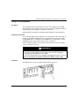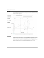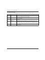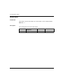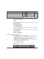
1
Modicon M340 with Unity Pro
EIO0000000318 07/2012
Modicon M340 with Unity
Pro
Counting Module BMX EHC 0800
User Manual
EIO0000000318.03
07/2012
www.schneider-electric.com
The information provided in this documentation contains general descriptions and/or
technical characteristics of the performance of the products contained herein. This
documentation is not intended as a substitute for and is not to be used for
determining suitability or reliability of these products for specific user applications. It
is the duty of any such user or integrator to perform the appropriate and complete
risk analysis, evaluation and testing of the products with respect to the relevant
specific application or use thereof. Neither Schneider Electric nor any of its affiliates
or subsidiaries shall be responsible or liable for misuse of the information that is
contained herein. If you have any suggestions for improvements or amendments or
have found errors in this publication, please notify us.
No part of this document may be reproduced in any form or by any means, electronic
or mechanical, including photocopying, without express written permission of
Schneider Electric.
All pertinent state, regional, and local safety regulations must be observed when
installing and using this product. For reasons of safety and to help ensure
compliance with documented system data, only the manufacturer should perform
repairs to components.
When devices are used for applications with technical safety requirements, the
relevant instructions must be followed.
Failure to use Schneider Electric software or approved software with our hardware
products may result in injury, harm, or improper operating results.
Failure to observe this information can result in injury or equipment damage.
© 2012 Schneider Electric. All rights reserved.
2
EIO0000000318 07/2012
Table of Contents
Safety Information . . . . . . . . . . . . . . . . . . . . . . . . . . . . . .
About the Book . . . . . . . . . . . . . . . . . . . . . . . . . . . . . . . . .
Part I Introduction to the BMX EHC 0800 Counting
Function . . . . . . . . . . . . . . . . . . . . . . . . . . . . . . . . . . .
Chapter 1 General Information on the BMX EHC 0800 Counting
Function. . . . . . . . . . . . . . . . . . . . . . . . . . . . . . . . . . . . . . .
General Information on Counting Functions . . . . . . . . . . . . . . . . . . . . . . .
Chapter 2 Presentation of BMX EHC 0800 Counting Module. . . . .
General Information about Counting Module . . . . . . . . . . . . . . . . . . . . . .
General Information about the Counting Module Operation . . . . . . . . . . .
Presentation of the BMX EHC 0800 Counting Module . . . . . . . . . . . . . . .
Modicon M340H (Hardened) Equipment. . . . . . . . . . . . . . . . . . . . . . . . . .
Chapter 3 Presentation of the BMX EHC 0800 Counting Module
Operation. . . . . . . . . . . . . . . . . . . . . . . . . . . . . . . . . . . . . .
7
9
11
13
13
15
16
17
18
20
21
Overview of BMX EHC 0800 Module Functionalities . . . . . . . . . . . . . . . .
21
Part II BMX EHC 0800 Counting Module Hardware
Implementation. . . . . . . . . . . . . . . . . . . . . . . . . . . . . .
23
Chapter 4 General Rules for Installing BMX EHC 0800 Counting
Module . . . . . . . . . . . . . . . . . . . . . . . . . . . . . . . . . . . . . . . .
Physical Description of the Counting Module . . . . . . . . . . . . . . . . . . . . . .
Fitting of Counting Module . . . . . . . . . . . . . . . . . . . . . . . . . . . . . . . . . . . .
Fitting a 20-Pin Terminal Block to a BMX EHC 0800 Counting Module . .
How to Connect the BMX EHC 0800 Counting Module: Connecting a 20Pin Terminal Block . . . . . . . . . . . . . . . . . . . . . . . . . . . . . . . . . . . . . . . . . .
Chapter 5 BMX EHC 0800 Counting Module Hardware
implementation . . . . . . . . . . . . . . . . . . . . . . . . . . . . . . . . .
Characteristics of the BMX EHC 0800 Module and its Inputs . . . . . . . . . .
Display and Diagnostics of the BMX EHC 0800 Counting Module . . . . . .
BMX EHC 0800 Module Wiring . . . . . . . . . . . . . . . . . . . . . . . . . . . . . . . . .
EIO0000000318 07/2012
25
26
27
29
33
37
38
40
43
3
Part III BMX EHC 0800 Counting Module Functionalities .
49
Chapter 6 BMX EHC 0800 Counting Module Functionalities. . . . . .
51
6.1 BMX EHC 0800 Module Configuration . . . . . . . . . . . . . . . . . . . . . . . . . .
Input Interface Blocks . . . . . . . . . . . . . . . . . . . . . . . . . . . . . . . . . . . . . . .
Programmable Filtering . . . . . . . . . . . . . . . . . . . . . . . . . . . . . . . . . . . . . .
Comparison . . . . . . . . . . . . . . . . . . . . . . . . . . . . . . . . . . . . . . . . . . . . . . .
Diagnostics . . . . . . . . . . . . . . . . . . . . . . . . . . . . . . . . . . . . . . . . . . . . . . .
Synchronization, Enable, Reset to 0 and Capture Functions . . . . . . . . .
Modulo Flag and Synchronization Flag . . . . . . . . . . . . . . . . . . . . . . . . . .
Sending Counting Events to the Application . . . . . . . . . . . . . . . . . . . . . .
6.2 BMX EHC 0800 Module Operation Modes . . . . . . . . . . . . . . . . . . . . . . .
BMX EHC 0800 Module Operation in Frequency Mode . . . . . . . . . . . . .
BMX EHC 0800 Module Operation in Event Counting Mode. . . . . . . . . .
BMX EHC 0800 Module Operation in One Shot Counter Mode . . . . . . .
BMX EHC 0800 Module Operation in Modulo Loop Counter Mode. . . . .
BMX EHC 0800 Module Operation in Upcounting and Downcounting
Mode . . . . . . . . . . . . . . . . . . . . . . . . . . . . . . . . . . . . . . . . . . . . . . . . . . . .
BMX EHC 0800 Module Operation in Dual Phase Counting Mode . . . . .
52
53
54
55
57
58
63
66
69
70
72
74
77
80
84
Part IV BMX EHC 0800 Counting Module Software
Implementation . . . . . . . . . . . . . . . . . . . . . . . . . . . . .
91
Chapter 7 Software Implementation Methodology for the
BMX EHC 0800 Counting Module . . . . . . . . . . . . . . . . . . .
93
Installation Methodology . . . . . . . . . . . . . . . . . . . . . . . . . . . . . . . . . . . . .
93
Chapter 8 Accessing the Functional Screens of the BMX EHC xxxx
Counting Modules . . . . . . . . . . . . . . . . . . . . . . . . . . . . . . .
4
95
Accessing the Functional Screens of the BMX EHC 0800 Counting
Modules . . . . . . . . . . . . . . . . . . . . . . . . . . . . . . . . . . . . . . . . . . . . . . . . .
Description of the Counting Module Screens. . . . . . . . . . . . . . . . . . . . . .
96
98
Chapter 9 Configuration of the BMX EHC 0800 Counting Module .
101
9.1 Configuration Screen for BMX EHC xxxx Counting Modules . . . . . . . . .
Configuration Screen for the BMX EHC 0800 Counting Module in a
Modicon M340 Local Rack. . . . . . . . . . . . . . . . . . . . . . . . . . . . . . . . . . . .
Configuration Screen for the BMX EHC 0800 Counting Module in X80
Drop . . . . . . . . . . . . . . . . . . . . . . . . . . . . . . . . . . . . . . . . . . . . . . . . . . . . .
9.2 Configuration of Modes for the BMX EHC 0800 Module . . . . . . . . . . . . .
Frequency Mode Configuration . . . . . . . . . . . . . . . . . . . . . . . . . . . . . . . .
Event Counting Mode Configuration . . . . . . . . . . . . . . . . . . . . . . . . . . . .
One Shot Counter Mode Configuration . . . . . . . . . . . . . . . . . . . . . . . . . .
Modulo Loop Counter Mode Configuration . . . . . . . . . . . . . . . . . . . . . . .
Up and Down Counting Mode Configuration . . . . . . . . . . . . . . . . . . . . . .
Dual Phase Counting Mode Configuration. . . . . . . . . . . . . . . . . . . . . . . .
102
103
105
107
108
109
110
111
112
113
EIO0000000318 07/2012
Chapter 10 BMX EHC 0800 Counting Module Adjusts . . . . . . . . . . .
Adjust Screen for BMX EHC 0800 Counting Module . . . . . . . . . . . . . . . .
Adjust the Preset Value. . . . . . . . . . . . . . . . . . . . . . . . . . . . . . . . . . . . . . .
Adjust the Calibration Factor . . . . . . . . . . . . . . . . . . . . . . . . . . . . . . . . . . .
Modulo Adjust . . . . . . . . . . . . . . . . . . . . . . . . . . . . . . . . . . . . . . . . . . . . . .
Adjust the Hysteresis Value . . . . . . . . . . . . . . . . . . . . . . . . . . . . . . . . . . .
Chapter 11 Debugging the BMX EHC 0800 Counting Module . . . . .
11.1 Debug Screen for BMX EHC xxxx Counting Modules . . . . . . . . . . . . . . .
Debug Screen for the BMX EHC 0800 Counting Module. . . . . . . . . . . . .
11.2 BMX EHC 0800 Module Debugging . . . . . . . . . . . . . . . . . . . . . . . . . . . . .
Frequency Mode Debugging . . . . . . . . . . . . . . . . . . . . . . . . . . . . . . . . . . .
Event Counting Mode Debugging . . . . . . . . . . . . . . . . . . . . . . . . . . . . . . .
One Shot Counter Mode Debugging . . . . . . . . . . . . . . . . . . . . . . . . . . . . .
Modulo Loop Counter Mode Debugging . . . . . . . . . . . . . . . . . . . . . . . . . .
Up and Down Counting Mode Debugging. . . . . . . . . . . . . . . . . . . . . . . . .
Dual Phase Counting Mode Debugging . . . . . . . . . . . . . . . . . . . . . . . . . .
Chapter 12 Display of BMX EHC xxxx Counting Module Error . . . .
Fault Display Screen for the BMX EHC 0800 Counting Module . . . . . . .
Faults Diagnostics Display . . . . . . . . . . . . . . . . . . . . . . . . . . . . . . . . . . . .
List of Errors . . . . . . . . . . . . . . . . . . . . . . . . . . . . . . . . . . . . . . . . . . . . . . .
Chapter 13 The Language Objects of the Counting Function . . . . .
13.1 The Language Objects and IODDT of the Counting Function. . . . . . . . . .
Introducing Language Objects for Application-Specific Counting . . . . . . .
Implicit Exchange Language Objects Associated with the ApplicationSpecific Function . . . . . . . . . . . . . . . . . . . . . . . . . . . . . . . . . . . . . . . . . . . .
Explicit Exchange Language Objects Associated with the ApplicationSpecific Function . . . . . . . . . . . . . . . . . . . . . . . . . . . . . . . . . . . . . . . . . . . .
Management of Exchanges and Reports with Explicit Objects . . . . . . . . .
13.2 Language Objects and IODDT Associated with the Counting Function of
the BMX EHC xxxx Modules. . . . . . . . . . . . . . . . . . . . . . . . . . . . . . . . . . .
Details of Implicit Exchange Objects for the T_Unsigned_CPT_BMX and
T_Signed_CPT_BMX-types IODDTs . . . . . . . . . . . . . . . . . . . . . . . . . . . .
Details of the Explicit Exchange Objects for the T_CPT_BMX-type IODDT
13.3 Device DDTs Associated with the Counting Function of the
BMX EHC xxxx Modules. . . . . . . . . . . . . . . . . . . . . . . . . . . . . . . . . . . . . .
Counter Device DDT Names. . . . . . . . . . . . . . . . . . . . . . . . . . . . . . . . . . .
13.4 The IODDT Type T_GEN_MOD Applicable to All Modules . . . . . . . . . . .
Details of the Language Objects of the IODDT of Type T_GEN_MOD. . .
Part V Quick Start: Example of Counting Module
Implementation. . . . . . . . . . . . . . . . . . . . . . . . . . . . . .
Chapter 14 Description of the Application. . . . . . . . . . . . . . . . . . . . .
Overview of the Application. . . . . . . . . . . . . . . . . . . . . . . . . . . . . . . . . . . .
EIO0000000318 07/2012
115
116
118
119
120
121
123
124
124
127
128
129
130
131
132
133
135
136
138
139
141
142
143
144
145
147
151
152
157
159
159
166
166
169
171
171
5
Chapter 15 Installing the Application Using Unity Pro . . . . . . . . . . .
15.1
174
174
176
177
178
181
183
185
187
188
191
193
Chapter 16 Starting the Application . . . . . . . . . . . . . . . . . . . . . . . . . .
195
15.2
6
173
Presentation of the Solution Used . . . . . . . . . . . . . . . . . . . . . . . . . . . . . .
Process Using Unity Pro . . . . . . . . . . . . . . . . . . . . . . . . . . . . . . . . . . . . .
Developing the Application . . . . . . . . . . . . . . . . . . . . . . . . . . . . . . . . . . .
Creating the Project . . . . . . . . . . . . . . . . . . . . . . . . . . . . . . . . . . . . . . . . .
Configuration of the Counting Module . . . . . . . . . . . . . . . . . . . . . . . . . . .
Declaration of Variables. . . . . . . . . . . . . . . . . . . . . . . . . . . . . . . . . . . . . .
Creating the Program for Managing the Counter Module . . . . . . . . . . . .
Creating the Labelling Program in ST . . . . . . . . . . . . . . . . . . . . . . . . . . .
Creating the I/O Event Section in ST . . . . . . . . . . . . . . . . . . . . . . . . . . . .
Creating a Program in LD for Application Execution . . . . . . . . . . . . . . . .
Creating an Animation Table . . . . . . . . . . . . . . . . . . . . . . . . . . . . . . . . .
Creating the Operator Screen . . . . . . . . . . . . . . . . . . . . . . . . . . . . . . . . .
Execution of Application in Standard Mode . . . . . . . . . . . . . . . . . . . . . . .
195
Index . . . . . . . . . . . . . . . . . . . . . . . . . . . . . . . . . . . . . . . . . . .
197
EIO0000000318 07/2012
Safety Information
§
Important Information
NOTICE
Read these instructions carefully, and look at the equipment to become familiar with
the device before trying to install, operate, or maintain it. The following special
messages may appear throughout this documentation or on the equipment to warn
of potential hazards or to call attention to information that clarifies or simplifies a
procedure.
EIO0000000318 07/2012
7
PLEASE NOTE
Electrical equipment should be installed, operated, serviced, and maintained only by
qualified personnel. No responsibility is assumed by Schneider Electric for any
consequences arising out of the use of this material.
A qualified person is one who has skills and knowledge related to the construction
and operation of electrical equipment and its installation, and has received safety
training to recognize and avoid the hazards involved.
8
EIO0000000318 07/2012
About the Book
At a Glance
Document Scope
This manual describes the hardware and software implementation of the
BMX EHC 0800 counting module for Modicon M340 PLCs and X80 drops.
Validity Note
This document is valid from Unity Pro v7.0.
Product Related Information
WARNING
UNINTENDED EQUIPMENT OPERATION
The application of this product requires expertise in the design and programming
of control systems. Only persons with such expertise should be allowed to
program, install, alter, and apply this product.
Follow all local and national safety codes and standards.
Failure to follow these instructions can result in death, serious injury, or
equipment damage.
User Comments
We welcome your comments about this document. You can reach us by e-mail at
[email protected].
EIO0000000318 07/2012
9
10
EIO0000000318 07/2012
Modicon M340 with Unity Pro
Overview
EIO0000000318 07/2012
Introduction to the BMX EHC 0800
Counting Function
I
Subject of this Part
This part provides a general introduction to the counting function and the operating
principles of the module.
What Is in This Part?
This part contains the following chapters:
Chapter
EIO0000000318 07/2012
Chapter Name
Page
1
General Information on the BMX EHC 0800 Counting Function
13
2
Presentation of BMX EHC 0800 Counting Module
15
3
Presentation of the BMX EHC 0800 Counting Module
Operation
21
11
Overview
12
EIO0000000318 07/2012
Modicon M340 with Unity Pro
BMX EHC 0800 Counting Functions
EIO0000000318 07/2012
General Information on the
BMX EHC 0800 Counting Function
1
General Information on Counting Functions
At a Glance
The counting function enables fast counting using couplers, Unity Pro screens and
specialized language objects. The general operation of expert modules also known
as couplers is described in the section Presentation of the Counting Module
Operation BMX EHC 0800.
In order to implement the counting, it is necessary to define the physical context in
which it is to be executed (rack, supply, processor, modules etc.) and to ensure the
software implementation (see page 91).
This second aspect is performed from the different Unity Pro editors:
z
z
EIO0000000318 07/2012
in offline mode
in online mode
13
BMX EHC 0800 Counting Functions
14
EIO0000000318 07/2012
Modicon M340 with Unity Pro
BMX EHC 0800 Counting Module
EIO0000000318 07/2012
Presentation of BMX EHC 0800
Counting Module
2
Subject of this Chapter
This chapter deals with the BMX EHC 0800 counting mode of the Modicon M340
range.
What Is in This Chapter?
This chapter contains the following topics:
Topic
General Information about Counting Module
EIO0000000318 07/2012
Page
16
General Information about the Counting Module Operation
17
Presentation of the BMX EHC 0800 Counting Module
18
Modicon M340H (Hardened) Equipment
20
15
BMX EHC 0800 Counting Module
General Information about Counting Module
Introduction
The BMX EHC 0800 counting module is a standard format module that enable
pulses from a sensor to be counted at a maximum frequency of 10 KHz.
This module has 8 channels.
This module may be installed in any available slot in a Modicon M340 PLC station
rack.
Sensors Used
The sensors used on each channel may be:
24 VDC two-wire proximity sensors
z 24 VDC three-wire proximity sensors
z Incremental signal encoders with 10/30 VDC output and push-pull outputs.
z
Illustration
The illustration below shows the following:
1) Incremental encoder
2) Proximity sensors
3) BMX EHC 0800 counting module
1
3
2
16
EIO0000000318 07/2012
BMX EHC 0800 Counting Module
General Information about the Counting Module Operation
Introduction
The BMX EHC 0800 module is a counting module from the Modicon M340 modular
PLC range. It support all Unity Pro software functionalities.
This module has:
z
z
z
Counting-related functions (comparison, capture, homing, reset to 0)
Event generation functions designed for the application program
Outputs for actuator use (contacts, alarms, relays)
Characteristics
The main characteristics of this module are as follows.
Type
Application
Number of
channels
per module
Number of
physical
inputs per
channel
Number of
physical
outputs per
channel
Maximum
frequency
BMX EHC 0800
z
z
z
z
8
2 in single
mode
3 in special
dual phase
mode
0
10 KHz
EIO0000000318 07/2012
Counting
Downcounting
Frequency meter
Encoder interface
17
BMX EHC 0800 Counting Module
Presentation of the BMX EHC 0800 Counting Module
At a Glance
The BMX EHC 0800 counting module enables the counting or downcounting of
pulses to be performed. It has the following functions:
z
z
z
z
Enable
Capture
Comparison
Load to preset value or reset to 0
16 bits structure
The following illustration shows the 16 bits structure of a counter channel:
A
COUNTER
Comparator
1 record
16 bits
register
Counter/Threshold
Or
record/Threshold
Aux
The diagram above is applicable for the following 5 counting modes:
z
z
z
z
z
18
Frequency mode
Event counting mode
One shot counter mode
Modulo loop counter mode
Up and down counter mode
EIO0000000318 07/2012
BMX EHC 0800 Counting Module
32 bits structure
The following illustration shows the 32 bits structure using 2 channels:
A
Comparator
COUNTER
B
1 record
32 bits
register
Counter/Threshold
Or
record/Threshold
Aux
The illustration shown above is only applicable for the dual-phase counter mode.
In this mode, with the counting module it is possible to merge 2 single channels into
1 dual-phase channel. As such, it is possible to build up to 4 encoder interfaces.
EIO0000000318 07/2012
19
BMX EHC 0800 Counting Module
Modicon M340H (Hardened) Equipment
M340H
The Modicon M340H (hardened) equipment is a ruggedized version of M340
equipment. It can be used at extended temperatures (-25...70ºC) (-13...158ºF) and
in harsh chemical environments.
This treatment increases the isolation capability of the circuit boards and their
resistance to:
z condensation
z dusty atmospheres (conducting foreign particles)
z chemical corrosion, in particular during use in sulphurous atmospheres (oil,
refinery, purification plant and so on) or atmospheres containing halogens
(chlorine and so on)
The M340H equipment, when within the standard temperature range (0...60ºC)
(32...140ºF), has the same performance characteristics as the standard M340
equipment.
At the temperature extremes (-25... 0ºC and 60... 70ºC) (-13...32ºF) and
(140...158ºF) the hardened versions can have reduced power ratings that impact
power calculations for Unity Pro applications.
If this equipment is operated outside the -25...70ºC (-13...158ºF) temperature range,
the equipment can operate abnormally.
CAUTION
UNINTENDED EQUIPMENT OPERATION
Do not operate M340H equipment outside of its specified temperature range.
Failure to follow these instructions can result in injury or equipment damage.
Hardened equipment has a conformal coating applied to its electronic boards. This
protection, when associated with appropriate installation and maintenance, allows it
to be more robust when operating in harsh chemical environments.
20
EIO0000000318 07/2012
Modicon M340 with Unity Pro
BMX EHC 0800 Counting Module
EIO0000000318 07/2012
Presentation of the
BMX EHC 0800 Counting Module
Operation
3
Overview of BMX EHC 0800 Module Functionalities
At a Glance
This part presents the different types of user applications for the BMX EHC 0800
module.
Measurement
The following table presents the measurement functionality for the BMX EHC 0800
module:
User application type
Mode
Speed measurement/stream measurement
Frequency
Random events monitoring
Event counting
Counting
The following table presents the counting functionality for the BMX EHC 0800
module:
User application type
Mode
Grouping
One shot counter
Level 1 packaging/labeling
Modulo loop counter
Accumulator
Up and down counting
Encoder interface
Dual phase counting
NOTE: In case of a user application such as level 1 packaging/labeling, the machine
makes constant spacing between parts.
EIO0000000318 07/2012
21
BMX EHC 0800 Counting Module
Interface
The BMX EHC 0800 module may be interfaced with the following components:
z
z
z
z
22
mechanical switch
24 VDC two-wire proximity sensor
24 VDC three-wire proximity sensor
10/30 VDC encoder with push-pull outputs
EIO0000000318 07/2012
Modicon M340 with Unity Pro
BMX EHC 0800 Counting Module Hardware Implementation
EIO0000000318 07/2012
BMX EHC 0800 Counting Module
Hardware Implementation
II
Subject of this Part
This part presents the hardware implementation of the BMX EHC 0800 counting
module.
What Is in This Part?
This part contains the following chapters:
Chapter
EIO0000000318 07/2012
Chapter Name
Page
4
General Rules for Installing BMX EHC 0800 Counting Module
25
5
BMX EHC 0800 Counting Module Hardware implementation
37
23
BMX EHC 0800 Counting Module Hardware Implementation
24
EIO0000000318 07/2012
Modicon M340 with Unity Pro
BMX EHC 0800 Counting Module: General Rules for Installation
EIO0000000318 07/2012
General Rules for Installing
BMX EHC 0800 Counting Module
4
Subject of this Chapter
This chapter presents the general rules for installing the BMX EHC 0800 counting
module.
What Is in This Chapter?
This chapter contains the following topics:
Topic
Physical Description of the Counting Module
EIO0000000318 07/2012
Page
26
Fitting of Counting Module
27
Fitting a 20-Pin Terminal Block to a BMX EHC 0800 Counting Module
29
How to Connect the BMX EHC 0800 Counting Module: Connecting a 20-Pin
Terminal Block
33
25
BMX EHC 0800 Counting Module: General Rules for Installation
Physical Description of the Counting Module
Illustration
The figure below present the counting module BMX EHC 0800:
Physical Elements of the Module
The table below presents the elements of the counting module:
Module
Number
BMX EHC 0800
1
Description
Module state LEDs:
z State LEDs at module level
z State LEDs at channel level
2
20-pin connector compatible with discrete
inputs/outputs
Accessories
The BMX EHC 0800 module requires the use of a BMX FTB 2000/2010/2020
terminal block and a BMX XSP 0400/0600/0800/1200 electromagnetic compatibility
kit (see Modicon M340 Using Unity Pro, Processors, Racks, and Power Supply
Modules, Setup Manual).
26
EIO0000000318 07/2012
BMX EHC 0800 Counting Module: General Rules for Installation
Fitting of Counting Module
At a Glance
The counting module is powered by the rack bus. The module may be handled
without turning off power supply to the rack, without causing any danger and without
there being any risk of damage or disturbance to the PLC.
Fitting operations (installation, assembly and disassembly) are described below.
Installation Precautions
The counting module may be installed in any of the positions in the rack except for
the first two (marked PS and 00) which are reserved for the rack’s power supply
module (BMX CPS ••••) and the processor (BMX P34 ••••) respectively. Power is
supplied by the bus at the bottom of the rack (3.3 V and 24 V).
Before installing a module, you must take off the protective cap from the module
connector located on the rack.
DANGER
HAZARD OF ELECTRIC SHOCK
z
z
disconnect voltage supplying sensors and pre-actuators before plugging /
unplugging the terminal block on the module.
remove the terminal block before plugging / unplugging the module on the rack.
Failure to follow these instructions will result in death or serious injury.
Installation
The diagram below shows counting module mounted on the rack:
EIO0000000318 07/2012
27
BMX EHC 0800 Counting Module: General Rules for Installation
The following table describes the different elements which make up the assembly
below:
Number
Description
1
BMX EHC 0800 counting module
2
Standard rack
Installing the Module on the Rack
The following table shows the procedure for mounting the counting module in the
rack:
Step
28
Action
Illustration
1
Position the locating pins situated at
the rear of the module (on the bottom
part) in the corresponding slots in the
rack.
Note: Before positioning the pins,
make sure you have removed the
protective cover (see Modicon M340
Using Unity Pro, Processors, Racks,
and Power Supply Modules, Setup
Manual).
Steps 1 and 2
2
Swivel the module towards the top of
the rack so that the module sits flush
with the back of the rack. It is now set
in position.
3
Tighten the safety screw to ensure that Step 3
the module is held in place on the rack.
Tightening torque: Max. 1.5 N.m
EIO0000000318 07/2012
BMX EHC 0800 Counting Module: General Rules for Installation
Fitting a 20-Pin Terminal Block to a BMX EHC 0800 Counting Module
At a Glance
The BMX EHC 0800 counting module with 20-pin terminal block connections
require the latter to be connected to the module. These fitting operations (assembly
and disassembly) are described below.
Installing the 20-Pin Terminal Block
The following table shows the procedure for assembling the 20-pin terminal block
onto a BMX EHC 0800 counting module:
DANGER
ELECTRICAL SHOCK
Terminal blocks must be connected or disconnected with sensor and pre-actuator voltage switched off.
Failure to follow these instructions will result in death or serious injury.
Assembly procedure:
Step
Action
1
Once the module is in place on the rack, install the terminal block by inserting the terminal block encoder
(the rear lower part of the terminal) into the module’s encoder (the front lower part of the module), as
shown above.
2
Fix the terminal block to the module by tightening the 2 mounting screws located on the lower and upper
parts of the terminal block.
Tightening torque: 0.4 N.m.
NOTE: If the screws are not tightened, there is a risk that the terminal block will not
be properly fixed to the module.
EIO0000000318 07/2012
29
BMX EHC 0800 Counting Module: General Rules for Installation
Coding the 20-Pin Terminal Block
When a 20-pin terminal block is installed on a module dedicated to this type of
terminal block, you can code the terminal block and the module using studs. The
purpose of the studs is to prevent the terminal block from being mounted on another
module. Handling errors can then be avoided when replacing a module.
Coding is done by the user with the STB XMP 7800 guidance wheel’s studs. You
can only fill the 6 slots in the middle of the left side (as seen from the wiring side) of
the terminal block, and can fill the module’s 6 guidance slots on the left side.
To fit the terminal block to the module, a module slot with a stud must correspond to
an empty slot in the terminal block, or a terminal block with a stud must correspond
to an empty slot in the module. You can fill up to and including either of the
6 available slots as desired.
The diagram below shows a guidance wheel as well as the slots on the module used
for coding the 20-pin terminal blocks:
30
EIO0000000318 07/2012
BMX EHC 0800 Counting Module: General Rules for Installation
The diagram below shows an example of a coding configuration that makes it
possible to fit the terminal block to the module:
The diagram below shows an example of coding configuration with which it is not
possible to fit the terminal block to the module:
DANGER
ELECTRICAL SHOCK
Terminal blocks must be connected or disconnected with sensor and pre-actuator
voltage switched off.
Failure to follow these instructions will result in death or serious injury.
EIO0000000318 07/2012
31
BMX EHC 0800 Counting Module: General Rules for Installation
CAUTION
DESTRUCTION OF THE MODULE
Code the terminal block as described above to prevent the terminal block from
being mounted on another module.
Plugging the wrong connector could cause the module to be destroyed.
Failure to follow these instructions can result in injury or equipment damage.
CAUTION
UNEXPECTED BEHAVIOUR OF APPLICATION
Code the terminal block as described above to prevent the terminal block from
being mounted on another module.
Plugging the wrong connector could cause unexpected behaviour of the
application.
Failure to follow these instructions can result in injury or equipment damage.
NOTE: The module connector have indicators which show the proper direction to
use for terminal block installation.
32
EIO0000000318 07/2012
BMX EHC 0800 Counting Module: General Rules for Installation
How to Connect the BMX EHC 0800 Counting Module: Connecting a 20-Pin
Terminal Block
At a Glance
There are 3 types of 20-pin terminal blocks:
z
z
z
BMX FTB 2010 screw clamp terminal blocks,
BMX FTB 2000 caged terminal blocks,
BMX FTB 2020 spring terminal blocks.
Cable Ends and Contacts
Each terminal block can accommodate:
z
Bare wires
z
Wires with DZ5-CE type cable ends:
Description of the 20-Pin Terminal Blocks
The table below shows the description of the 3 types of 20-pin terminal blocks:
Screw clamp terminal
blocks
Caged terminal blocks
Spring terminal blocks
2
1
1
Illustration
Number of wires
accommodated
Number of
wire gauges accommodated
minimum
AWG 24 (0.34 mm2)
maximum AWG 16 (1.5 mm2)
EIO0000000318 07/2012
33
BMX EHC 0800 Counting Module: General Rules for Installation
Wiring constraints
Maximum screw
tightening torque
Screw clamp terminal
blocks
Caged terminal blocks
Spring terminal blocks
Screw clamps have slots that
accept:
z flat-tipped screwdrivers
with a diameter of 5 mm,
z posidriv n°1 cross-tipped
screwdrivers.
Caged terminal blocks have
slots that accept:
z flat-tipped screwdrivers
with a diameter of 3 mm,
z posidriv n°1 cross-tipped
screwdrivers.
Screw clamp terminal blocks
have captive screws. On the
supplied blocks, these screws
are not tightened.
Caged terminal blocks have
captive screws. On the
supplied blocks, these
screws are not tightened.
The wires are connected by
pressing on the button
located next to each pin.
To press on the button, you
have to use a flat-tipped
screwdriver with a maximum
diameter of 3 mm.
0.5 N.m.
0.5 N.m.
-
DANGER
ELECTRICAL SHOCK
The terminal block must be connected or disconnected with sensor and preactuator voltage switched off.
Failure to follow these instructions will result in death or serious injury.
34
EIO0000000318 07/2012
BMX EHC 0800 Counting Module: General Rules for Installation
Connection of 20-Pin Terminal Blocks
The following diagram shows the method for opening the 20-pin terminal block door
so that it can be wired:
NOTE: The connection cable is installed and held in place by a cable clamp
positioned below the 20-pin terminal block.
Labeling of 20-Pin Terminal Blocks
The labels for the 20-pin terminal blocks are supplied with the module. They are to
be inserted in the terminal block cover by the customer.
Each label has two sides:
z
z
EIO0000000318 07/2012
One side that is visible from the outside when the cover is closed. This side
features the commercial product references, an abbreviated description of the
module as well as a blank section for customer labeling.
One side that is visible from the inside when the cover is open. This side shows
the terminal block connection diagram.
35
BMX EHC 0800 Counting Module: General Rules for Installation
36
EIO0000000318 07/2012
Modicon M340 with Unity Pro
BMX EHC 0800
EIO0000000318 07/2012
BMX EHC 0800 Counting Module
Hardware implementation
5
Subject of this Chapter
This chapter deals with the harware characteristics and diagnostics of the
BMX EHC 0800 module.
What Is in This Chapter?
This chapter contains the following topics:
Topic
Characteristics of the BMX EHC 0800 Module and its Inputs
EIO0000000318 07/2012
Page
38
Display and Diagnostics of the BMX EHC 0800 Counting Module
40
BMX EHC 0800 Module Wiring
43
37
BMX EHC 0800
Characteristics of the BMX EHC 0800 Module and its Inputs
General Characteristics
This table presents the general characteristics for the BMX EHC 0800 and
BMX EHC 0800H (see page 20) modules:
Module type
8 counting channels
Counter size
16 bits
Maximum frequency at counting inputs
10 kHz
Number of inputs/outputs per counting
channel
Inputs
Outputs
0
Power Supply
Sensor supply voltage
19.2...30 VDC
Module consumption
Does not take into account sensors or
encoder consumption
z All inputs OFF: typical: 15 mA
z All inputs ON: typical: 80 mA
2 inputs in single mode
3 inputs in special dual phase mode
Power distribution to sensors
No
Hot replacement
Yes, under the following conditions:
The module may be removed and reinserted
into its location while the rack is switched on,
but the counter may have to be revalidated
when it is reinserted into its base.
Dimensions
Width
Height
Depth
Encoder compliance
Module only
32 mm
On the rack
32 mm
Module only
103.76 mm
On the rack
103.76 mm
Module only
92 mm
On the rack
104.5 mm
10...30 VDC incremental encoder model with
push-pull at outputs
Insulation voltage
Of the ground to the bus
1500 V RMS for 1 min
Rack 24 V supply bus
Current for the 24 V bus
Typical: 40 mA
Rack 3 V supply bus
Current for the 3 V bus
Typical: 200 mA
Cycle Time
38
5 ms
EIO0000000318 07/2012
BMX EHC 0800
WARNING
OVERHEATING MODULE
Do not operate the BMX EHC 0800H at 70°C (158°F) if the sensor power supply
is greater than 26.4 V or less than 21.1 V.
Failure to follow these instructions can result in death, serious injury, or
equipment damage.
Input Characteristics
This table presents the general characteristics of the input channels for the module:
Number of inputs per channel
Inputs: IN_A, IN_AUX
Two 24 VDC inputs
Voltage
At state 1
At state 0
30 VDC
Voltage
11 VDC...30 VDC
Current
4.5 mA (up to 30 VDC)
Voltage
< 5 VDC
Current
< 1.5 mA
Current at 11 VDC
EIO0000000318 07/2012
> 2 mA
39
BMX EHC 0800
Display and Diagnostics of the BMX EHC 0800 Counting Module
At a Glance
The BMX EHC 0800 counting module has LEDs that enable the following to be
viewed:
z
z
the status of the module: RUN, ERR, I/O
the input status of every channel
Illustration
The following drawing shows the display screen of the BMX EHC 0800 module:
40
EIO0000000318 07/2012
BMX EHC 0800
Fault Diagnostics
The following table enables the diagnostics of errors according to the various LEDs.
Module status
LED indicators
RUN
ERR
I/O
C0
C1
C2
C3
C4
C5
C6
C7
The module is inoperative or
switched off
The module has an error
The module is not configured
The module has lost
communication
The sensors have a supply error
The channels are operational
The voltage is present at input
IN_A of counter 0
The voltage is present at input
IN_A of counter 1
The voltage is present at input
IN_A of counter 2
The voltage is present at input
IN_A of counter 3
The voltage is present at input
IN_A of counter 4
The voltage is present at input
IN_A of counter 5
The voltage is present at input
IN_A of counter 6
The voltage is present at input
IN_A of counter 7
EIO0000000318 07/2012
41
BMX EHC 0800
Module status
LED indicators
RUN
ERR
I/O
A0
A1
A2
A3
A4
A5
A6
A7
The channels are operational
The voltage is present at input
IN_AUX of counter 0
The voltage is present at input
IN_AUX of counter 1
The voltage is present at input
IN_AUX of counter 2
The voltage is present at input
IN_AUX of counter 3
The voltage is present at input
IN_AUX of counter 4
The voltage is present at input
IN_AUX of counter 5
The voltage is present at input
IN_AUX of counter 6
The voltage is present at input
IN_AUX of counter 7
Legend
LED on
LED off
LED flashing slowly
LED flashing fast
An empty cell indicates that the state of the LED(s) is not taken into account
42
EIO0000000318 07/2012
BMX EHC 0800
BMX EHC 0800 Module Wiring
At a Glance
The BMX EHC 0800 counting module uses a standard BMX FTB 2000/2010/2020
20-pin connector (wiring terminal) .
DANGER
HAZARD OF ELECTRIC SHOCK
z
z
disconnect voltage supplying sensors and pre-actuators before plugging /
unplugging the terminal block on the module.
remove the terminal block before plugging / unplugging the module on the rack.
Failure to follow these instructions will result in death or serious injury.
Field Sensors
The module has type 3 inputs that support signals from mechanical switching
equipment such as contact relays, push-buttons, limit switch sensors and two or
three-wire switches that have:
z
z
z
a voltage drop of less than 8V,
current when ON more than or equal to 2 mA,
current when OFF up to 1.5 mA.
The module complies with all encoders that have a supply of between 10 and
30 VDC and push-pull outputs. Shielding is required if there is no filtering.
Pin Assignments
The following table describes the assignment of the 20-pin wiring terminal:
IN_A input for channel 0
EIO0000000318 07/2012
2
1
IN_AUX input for channel 0
IN_A input for channel 1 or 4
IN_B input for channel 0
3
IN_AUX input for channel 1
IN_A input for channel 2
6
5
IN_AUX input for channel 2
IN_A input for channel 3 or 8
IN_B input for channel 2
7
IN_AUX input for channel 3
IN_A input for channel 4
9
IN_AUX input for channel 4
IN_A input for channel 5 or 12
in_B input for channel 4
11
IN_AUX input for channel 5
IN_A input for channel 6
13
IN_AUX input for channel 6
10
14
43
BMX EHC 0800
IN_A input for channel 7 or 16
IN_B input for channel 6
15
IN_AUX input for channel 7
VDC + power supply for
sensors
18
17
Return + 24 V power supply for sensors
Functional earth, for shield 20
continuation
19
Functional earth, for shield continuation
Sensor Connection Example
The example below shows the most complete application using sensors:
44
EIO0000000318 07/2012
BMX EHC 0800
Encoder Connection Example
The example below shows an incremental encoder connection used for axis control
connected to the counter’s channel 6 used in dual phase counting mode:
Channels 0 to 5 are still used in single mode.
Channel 7 is no longer available.
EIO0000000318 07/2012
45
BMX EHC 0800
Safety Instructions
WARNING
UNEXPECTED EQUIPMENT OPERATION
Follow those instructions to reduce electromagnetic perturbations:
z adapt the programmable filtering to the frequency applied at the inputs, or
z use a shielded cable (connected to the functional ground) connected to pins 15
and 16 of the connector when using an encoder or a fast detector.
In a highly disturbed environment,
z use the BMX XSP 0400/0600/0800/1200 electromagnetic protection kit
(see Modicon M340 Using Unity Pro, Processors, Racks, and Power Supply
Modules, Setup Manual) (See Modicon M340 using Unity Pro, Processors,
Racks and Power Supply Modules, BMX XSP xxx Protection Bar) to connect
the shielding without programmable filtering and
z use a specific 24 VDC supply for inputs and a shielded cable for connecting the
supply to the module.
Electromagnetic perturbations may cause the application to operate in an
unexpected manner.
Failure to follow these instructions can result in death, serious injury, or
equipment damage.
46
EIO0000000318 07/2012
BMX EHC 0800
The figure below shows the recommended circuit for a highly disturbed environment
using the BMX XSP 0400/0600/0800/1200 electromagnetic protection kit:
CAUTION
POTENTIAL MODULE DAMAGE - IMPROPER FUSE SELECTION
Use fast acting fuses to protect the electronic components of the module from
overcurrent and reverse polarity of the input/output supplies. Improper fuse
selection could result to damage to the module.
Failure to follow these instructions can result in injury or equipment damage.
EIO0000000318 07/2012
47
BMX EHC 0800
48
EIO0000000318 07/2012
Modicon M340 with Unity Pro
BMX EHC 0800 Counting Module Functionalities
EIO0000000318 07/2012
BMX EHC 0800 Counting Module
Functionalities
EIO0000000318 07/2012
III
49
BMX EHC 0800 Counting Module Functionalities
50
EIO0000000318 07/2012
Modicon M340 with Unity Pro
BMX EHC 0800 Functionalities
EIO0000000318 07/2012
BMX EHC 0800 Counting Module
Functionalities
6
Subject of this Chapter
This chapter deals with functionalities and counting modes of the BMX EHC 0800
module.
What Is in This Chapter?
This chapter contains the following sections:
Section
EIO0000000318 07/2012
Topic
Page
6.1
BMX EHC 0800 Module Configuration
52
6.2
BMX EHC 0800 Module Operation Modes
69
51
BMX EHC 0800 Functionalities
6.1
BMX EHC 0800 Module Configuration
Subject of this Section
This section deals with the configuration of the BMX EHC 0800 module.
What Is in This Section?
This section contains the following topics:
Topic
52
Page
Input Interface Blocks
53
Programmable Filtering
54
Comparison
55
Diagnostics
57
Synchronization, Enable, Reset to 0 and Capture Functions
58
Modulo Flag and Synchronization Flag
63
Sending Counting Events to the Application
66
EIO0000000318 07/2012
BMX EHC 0800 Functionalities
Input Interface Blocks
Description
The BMX EHC 0800 counting module has three fast inputs:
Fast Inputs
The table below presents the module’s fast inputs.
Input
Use with available sensors
Use with an encoder
IN_A input
Clock input for measurement or single upcounting
For signal A
IN_B input
From the following
channel
Second clock input for differential counting or
measurement
For signal B
IN_AUX input
Multi-function input used for:
z synchronization
z preset and start
z reset and record
z capture
z counting direction (upcounting/downcounting
mode)
For signal Z
Used for preset
EIO0000000318 07/2012
53
BMX EHC 0800 Functionalities
Programmable Filtering
At a Glance
The BMX EHC 0800 counting module’s two (or three) inputs are compatible with the
use of mechanical switches.
A programmable debounce filter with 3 levels (low, medium and high) is available at
every input.
Debounce Filter Diagram
The figure below shows the debounce filter in low mode:
In this mode, the system delays all transitions until the signal is stable for 450 μs.
Selecting the Filtering Level
The table below specifies the characteristics of each input for the selected level of
filtering:
Filtering level
None
54
Input
Minimum
pulse
Maximum
frequency
IN_A, IN_B
50 μs
10 KHz
IN_AUX
50 μs
40 Hz
Low
for bounces > 2 KHz
IN_A, (IN_B)
450 μs
1 KHz
IN_AUX
450 μs
40 Hz
Resource
for bounces > 1 KHz
IN_A, IN_B
1.25 ms
350 Hz
IN_AUX
1.25 μs
40 Hz
High
for bounces > 250 Hz
IN_A, IN_B
4.2 ms
100 Hz
IN_AUX
4.2 ms
40 Hz
EIO0000000318 07/2012
BMX EHC 0800 Functionalities
Comparison
At a Glance
The comparison block operates automatically when it is enabled. It is available in all
the BMX EHC 0800 module’s counting modes.
It compares the current value of the counter together with the capture value at the
defined threshold.
Comparison Threshold
The comparison block has one threshold only. Its value is contained in the
lower_th_value double word (%QDr.m.c.2).
The threshold format is identical to the counter value format.
Comparison Status Register
The result of the comparison is stored in the comparison status register.
The value of the capture register and the current value of the counter are compared
with the thresholds.
The possible results are:
z
z
z
Low: The counter value is less than the lower threshold value.
Equal: The counter value is equal to the threshold.
High: The counter value is greater than the threshold.
The comparison status register consists of:
Position of
the status
register bit
15
14
13
12
11
10
9
8
7
6
5
Compared
element
Comparison
result
4
3
2
Capture
High
Equal
1
0
Counter
Low
High
Equal
Low
Update
When the compare_enable_bit is set to 0, the comparison status register is
deleted.
When the compare_suspend_bit is set to 1, the comparison status register is
frozen at its last value.
The comparison with capture register value is performed every time the registers are
loaded.
EIO0000000318 07/2012
55
BMX EHC 0800 Functionalities
The comparison with the counter current value is performed as follows:
Counting mode
Comparison register update
Frequency
Period intervals of 10 ms
Event counting
Period intervals defined by the user
Modulo loop counter
One of the following conditions:
z intervals of 5 ms
z counter reloading or resetting to 0
z counting direction change
z counter stops
z crossing of threshold
One shot counter
dual phase counting
Up and down
counting
56
EIO0000000318 07/2012
BMX EHC 0800 Functionalities
Diagnostics
Consistency Rules for Inputs Interface
The input interface requires that the sensor power supply remains active for
counting operations.
When the sensor power supply interrupts lasts 1 ms or less, the counter remains
stable.
In case of power interrupt is greater than 1 ms, all counter values are disabled.
By default, the sensor supply an error makes the CH_ERROR (%Ir.m.c.ERR) global
status bit at the high level and the red led IO lighted.
The configuration screen allows to unlink the sensor supply an error to the
CH_ERROR bit by configuring the parameter Input Supply Fault as local
instead of General IO Fault.
In all cases, after having executed the READ_STS (IODDT_VAR1) instruction, the
application provides the %MWr.m.c.2 and %MWr.m.c.3 standard status words
including the supply an error information.
IODDT_VAR1 is of the type T_Unsigned_CPT_BMX or T_Signed_CPT_BMX.
Explicit channel status words
The table below presents the composition of the %MWr.m.c.2 and %MWr.m.c.3
status words.
Status Word
Bit position
Designation
%MWr.m.c.2
0
External error at inputs
%MWr.m.c.3
4
Internal error or self-testing.
5
Configuration Fault
6
Communication Error
7
Application error
2
Sensor supply error
IO Data
All input/output statuses are provided in the channel data bits.
The table below shows the channel data bits:
EIO0000000318 07/2012
Input/Output data field
Designation
%Ir.m.c.4
Electrical state of IN_A input
%Ir.m.c.5
Electrical state of IN_B input
%Ir.m.c.6
Electrical state of IN_AUX input
57
BMX EHC 0800 Functionalities
Synchronization, Enable, Reset to 0 and Capture Functions
Introduction
This section presents the functions used by the various counting modes of the
BMX EHC 0800 module:
z Synchronization function
z Enable function
z Reset to 0 function
z Capture function
Each function uses at least one of the following two bits:
z valid_(function) bit: Setting this bit to 1 allows you to take into account the
occurrence of an external event which activates the function. If this bit is set to 0,
the event is not taken into account and does not activate the function. The
functions_enabling word (%QWr.m.c.0) contains all the
valid_(function) bits.
z force_(function) bit: Setting this bit to 1 allows you to activate the function
irrespective of the status of the external event. All the force_(function) bits
are %Qr.m.c.4...%Qr.m.c.8 language objects.
Synchronization Function
The synchronization function is used to synchronize the counter operation upon a
transition applied to the IN_AUX physical input or the force_sync bit set to 1.
This function is used in the following counting modes:
z Dual phase counting
z Modulo loop counter
z One shot counter
z Event counting
z Up and down counting (using the force_sync bit only)
In all of the counting modes specified above, with the exception of the up and down
counting mode, the user may configure the synchro edge parameter in the
configuration screen by choosing from the following two possibilities to configure the
external event:
z Rising edge of the IN_AUX input
z Falling edge of the IN_AUX input
58
EIO0000000318 07/2012
BMX EHC 0800 Functionalities
The following table presents the force_sync bit in bold which is an element of the
%Qr.m.c.d output command word:
Language
object
Standard symbol
Meaning
%Qr.m.c.0
OUTPUT_0
Forces OUTPUT_0 to level 1
%Qr.m.c.1
OUTPUT_1
Forces OUTPUT_1 to level 1
%Qr.m.c.2
OUTPUT_BLOCK_0_ENABLE Implementation of output 0 function block
%Qr.m.c.3
OUTPUT_BLOCK_1_ENABLE Implementation of output 1 function block
%Qr.m.c.4
FORCE_SYNC
%Qr.m.c.5
FORCE_REF
Set to preset counter value
%Qr.m.c.6
FORCE_ENABLE
Implementation of counter
%Qr.m.c.7
FORCE_RESET
Reset counter
%Qr.m.c.8
SYNC_RESET
Reset SYNC_REF_FLAG
%Qr.m.c.9
MODULO_RESET
Reset MODULO_FLAG
Counting function synchronization
and start
The following table presents the valid_sync bit in bold which is an element of the
%QWr.m.c.0 function enabling word:
Language
object
EIO0000000318 07/2012
Standard symbol
Meaning
%QWr.m.c.0.0 VALID_SYNC
Synchronization and start
authorization for the counting function
via the IN_SYNC input
%QWr.m.c.0.1 VALID_REF
Operation authorization for the internal
preset function
%QWr.m.c.0.2 VALID_ENABLE
Authorization of the counter enable via the
IN_EN input
%QWr.m.c.0.3 VALID_CAPT_0
Capture authorization in the capture0
register
%QWr.m.c.0.4 VALID_CAPT_1
Capture authorization in the capture1
register
%QWr.m.c.0.5 COMPARE_ENABLE
Comparators operation authorization
%QWr.m.c.0.6 COMPARE_SUSPEND
Comparator frozen at its last value
59
BMX EHC 0800 Functionalities
The following table presents the synchronization principle:
Edge
Status of the
valid_sync bit
Status of the counter
Rising or falling edge on IN_AUX Set to 0
(depending on the configuration)
Not synchronized
Rising or falling edge on IN_AUX Set to 1
(depending on the configuration)
Synchronized
Rising edge on force_sync bit Set to 0 or 1
Synchronized
When the synchronization occurs, the application can react using:
z either the SYNC_REF_FLAG input (%IWr.m.c.0.2) (see page 63)
z or the EVT_SYNC_PRESET input (%IWr.m.c.10.2) (see page 66).
Enable Function
This function is used to authorize changes to the counter value via software
command.
This function is used in the following counting modes:
Dual phase counting
z Up and down counting
z Modulo loop counter
z One shot counter
z
The following table presents the force_enable bit in bold which is an element of
the %Qr.m.c.d output command word:
Language
object
Standard symbol
Meaning
%Qr.m.c.0
OUTPUT_0
Forces OUTPUT_0 to level 1
%Qr.m.c.1
OUTPUT_1
Forces OUTPUT_1 to level 1
%Qr.m.c.2
OUTPUT_BLOCK_0_ENABLE
Implementation of output 0 function block
%Qr.m.c.3
OUTPUT_BLOCK_1_ENABLE
Implementation of output 1 function block
%Qr.m.c.4
FORCE_SYNC
Counting function synchronization and
start
%Qr.m.c.5
FORCE_REF
Set to preset counter value
%Qr.m.c.6
FORCE_ENABLE
Implementation of counter
%Qr.m.c.7
FORCE_RESET
Reset counter
%Qr.m.c.8
SYNC_RESET
Reset SYNC_REF_FLAG
%Qr.m.c.9
MODULO_RESET
Reset MODULO_FLAG
The function is activated by setting the force_enable bit to 1. There is no
valid_enable bit because the function is not activated by any physical input.
60
EIO0000000318 07/2012
BMX EHC 0800 Functionalities
Reset to 0 Function
This function is used to load the value 0 into the counter via software command.
This function is used in the following counting modes:
z Dual phase counting
z Up and down counting
z Modulo loop counter
z One shot counter
The following table presents the force_reset bit in bold which is an element of the
%Qr.m.c.d output command word:
Language
object
Standard symbol
Meaning
%Qr.m.c.0
OUTPUT_0
Forces OUTPUT_0 to level 1
%Qr.m.c.1
OUTPUT_1
Forces OUTPUT_1 to level 1
%Qr.m.c.2
OUTPUT_BLOCK_0_ENABLE
Implementation of output 0 function block
%Qr.m.c.3
OUTPUT_BLOCK_1_ENABLE
Implementation of output 1 function block
%Qr.m.c.4
FORCE_SYNC
Counting function synchronization and
start
%Qr.m.c.5
FORCE_REF
Set to preset counter value
%Qr.m.c.6
FORCE_ENABLE
Implementation of counter
%Qr.m.c.7
FORCE_RESET
Reset counter
%Qr.m.c.8
SYNC_RESET
Reset SYNC_REF_FLAG
%Qr.m.c.9
MODULO_RESET
Reset MODULO_FLAG
The function is activated by the rising edge of the force_reset bit. There is no
valid_reset bit because the function is not activated by any physical input.
Capture Function
This function is used to load the current counter value into the capt_0_val register
(%IDr.m.c.14) at the same condition defined by the synchro edge parameter
configured in the configuration screen (see page 58).
Each BMX EHC 0800 module channel has one capture register.
This function is used in the following counting modes:
z Dual phase counting
z Modulo loop counter
EIO0000000318 07/2012
61
BMX EHC 0800 Functionalities
The synchronization and capture functions may be enabled independently:
Status of the
valid_capt_0
bit
(%QWr.m.c.0.3)
Status of the
valid_sync bit
(%QWr.m.c.0.0)
Behavior while the capture condition (condition defined by the
synchro edge parameter) is true
Current counter value
Capture register value
(%ID r.m.c.14)
Set to 0
Set to 0
No change
No change
Set to 0
Set to 1
Reload or clear
No change
Set to 1
Set to 0
No change
Reload with current counter value
Set to 1
Set to 1
Reload or clear
Reload with current counter value
The storage will occur just before
reseting the counter value.
62
EIO0000000318 07/2012
BMX EHC 0800 Functionalities
Modulo Flag and Synchronization Flag
At a Glance
This section presents the operation of the bits relating to the following events:
z
z
Counter synchronization event
Counter rollovers the modulo or its limits in forward or reverse.
The table below presents the counting modes that may activate synchronization and
modulo events:
Flag
Counting mode concerned
sync_ref_flag bit
(%IWr.m.c.0.2)
z Dual phase counting: When the counter presets
and (re)starts
z Up and down counting: When the counter presets
and (re)starts
z Modulo loop counter: When the counter resets
z One shot counter: When the counter presets and
(re)starts
z Event counting: When the internal time base
restarts to the beginning.
modulo_flag bit (%IWr.m.c.0.1
z Dual phase counting: When the counter rollovers
its limits
z Up and down counting: When the counter
rollovers its limits
z Modulo loop counter: When the counter rollovers
the modulo or 0.
You can use these 2 flags without declaring any event task in configuration screen.
These 2 flag bits are refreshed by the task declared with the module channel (MAST
or FAST task).
Operation of the Flag Bits
The synchronization event’s flag bit is set to 1 when a counter synchronization
occurs.
The modulo event’s flag bit can be set to 1 in the following counting modes:
z
z
z
EIO0000000318 07/2012
Dual phase counting: The flag bit is set to 1 when the counter rollovers its limits
in forward or reverse
Up and down counting: The flag bit is set to 1 when the counter rollovers its limits
in forward or reverse
Modulo loop counter: The flag bit is set to 1 when the counter rollovers the
modulo.
63
BMX EHC 0800 Functionalities
Location of the Flag Bits
The following table presents the modulo_flag and sync_ref_flag bits which
are elements of the %IWr.m.c.d status word:
Language
object
Standard symbol
Meaning
%IWr.m.c.0.
0
RUN
The counter operates in one shot mode
only
%IWr.m.c.0.
1
MODULO_FLAG
Flag set to 1 by a modulo switch event
%IWr.m.c.0.
2
SYNC_REF_FLAG
Flag set to 1 by a preset or
synchronization event
%IWr.m.c.0.
3
VALIDITY
The current numerical value is valid
%IWr.m.c.0.
4
HIGH_LIMIT
The current numerical value is locked at the
upper threshold value
%IWr.m.c.0.
5
LOW_LIMIT
The current numerical value is locked at the
lower threshold value
Resetting the Flag Bits to 0
The user application must reset the flag bit to 0 (if it is active) by using the
appropriate command bit from the following two bits:
z
z
sync_reset bit to reset the synchronization event’s flag bit to 0
modulo_reset bit to reset the modulo event’s flag bit to 0
Location of Reset to 0 Commands
The following table presents the sync_reset and modulo_reset bits which are
elements of the %Qr.m.c.d output command word:
64
Language
object
Standard symbol
Meaning
%Qr.m.c.0
OUTPUT_0
Forces OUTPUT_0 to level 1
%Qr.m.c.1
OUTPUT_1
Forces OUTPUT_1 to level 1
%Qr.m.c.2
OUTPUT_BLOCK_0_ENABLE
Implementation of output 0 function
block
%Qr.m.c.3
OUTPUT_BLOCK_1_ENABLE
Implementation of output 1 function
block
%Qr.m.c.4
FORCE_SYNC
Counting function synchronization and
start
%Qr.m.c.5
FORCE_REF
Set to preset counter value
%Qr.m.c.6
FORCE_ENABLE
Implementation of counter
EIO0000000318 07/2012
BMX EHC 0800 Functionalities
EIO0000000318 07/2012
Language
object
Standard symbol
Meaning
%Qr.m.c.7
FORCE_RESET
Reset counter
%Qr.m.c.8
SYNC_RESET
Reset SYNC_REF_FLAG
%Qr.m.c.9
MODULO_RESET
Reset MODULO_FLAG
65
BMX EHC 0800 Functionalities
Sending Counting Events to the Application
At a Glance
The event task number must be declared in the module’s configuration screen to
enable the events sending.
The BMX EHC 0800 module has eight event sources contained in the
events_source word at the address %IWr.m.c.10:
Address
Standard Symbol
Description
Counting mode concerned
%IWr.m.c.10.0
EVT_RUN
Event due to start of
counting.
One Shot Counter mode
%IWr.m.c.10.1
EVT_MODULO
Event due to counter being
equal to modulo value - 1 or
equal to value 0.
z Modulo Loop Counter mode
z Up and Down Counter mode
z Dual Phase Counter mode
%IWr.m.c.10.2
EVT_SYNC_PRESET
Event due to a
synchronization or counter
homing.
z
z
z
z
Event Counter mode
One Shot Counter mode
Modulo Loop Counter mode
Dual Phase Counter mode
%IWr.m.c.10.3
EVT_COUNTER_LOW
Event due to counter being
less than threshold.
z
z
z
z
z
z
Frequency Counter mode
Event Counter mode
One Shot Counter mode
Modulo Loop Counter mode
Up and Down Counter mode
Dual Phase Counter mode
%IWr.m.c.10.4
EVT_COUNTER_
WINDOW
Event due to counter being
equal to threshold.
%IWr.m.c.10.5
EVT_COUNTER_HIGH Event due to counter being
greater than threshold.
z
z
z
z
z
z
Frequency Counter mode
Event Counter mode
One Shot Counter mode
Modulo Loop Counter mode
Up and Down Counter mode
Dual Phase Counter mode
%IWr.m.c.10.6
EVT_CAPT_0
Event due to capture 0.
z Modulo Loop Counter mode
z Up and Down Counter mode
z Dual Phase Counter mode
%IWr.m.c.10.7
EVT_CAPT_1
Event due to capture 1.
%IWr.m.c.10.8
EVT_OVERRUN
Event due to overrun.
66
z
z
z
z
z
z
Frequency Counter mode
Event Counter mode
One Shot Counter mode
Modulo Loop Counter mode
Up and Down Counter mode
Dual Phase Counter mode
EIO0000000318 07/2012
BMX EHC 0800 Functionalities
All the events sent by the module, whatever their source, call the same single event
task in the PLC.
There is normally only one type of event indicated per call.
The evt_sources (%IWr.m.c.10) is updated at the start of the event task
processing.
Enabling Events
In order for a source to produce an event, the validation bit corresponding to the
event must be set to 1:
Address
Description
%QWr.m.c.1.0
Start of counting event validation bit.
%QWr.m.c.1.1
Counter rollovering modulo, 0 or its limits event
validation bit.
%QWr.m.c.1.2
Synchronization or counter homing event
validation bit.
%QWr.m.c.1.3
Counter less than threshold event validation bit.
%QWr.m.c.1.4
Counter equal to threshold event validation bit.
%QWr.m.c.1.5
Counter greater than threshold event validation
bit.
%QWr.m.c.1.6
Capture 0 event validation bit.
Input Interface
The event only has one input interface. This interface is only updated at the start of
the event task processing. The interface consists of:
z
z
z
The evt_sources word (%IWr.m.c.10)
The current value of the counter during the event (or an approximate value)
contained in the counter_current_value word (%IDr.m.c.12)
The capt_0_val register (%IDr.m.c.14) updated if the event is the capture 0.
Operating Limits
Each counter channel can produce a maximum of one event per millisecond, but this
flow may be slowed down by simultaneously sending events to several modules on
the PLC bus.
Each counter channel has a two slot transmission buffer which can be used to store
several events while waiting to be sent.
If the counter channel is unable to send all of the internally produced events, the
overrun_evt bit (address %IWr.m.c.10.8) of the events_source word is set
to 1.
EIO0000000318 07/2012
67
BMX EHC 0800 Functionalities
The following two points should be taken into account before using the "Counter
equal", "Counter high" and "Counter low" events:
z For frequency mode: due to the accuracy (+/-1 Hz), a frequency near the
threshold can cause redundant events.
z For counting function modes: when the counter matches the threshold value, the
input frequency must be lower than 400 Hz in order to detect the event.
68
EIO0000000318 07/2012
BMX EHC 0800 Functionalities
6.2
BMX EHC 0800 Module Operation Modes
Subject of this Section
This section deals with the different counting modes of the BMX EHC 0800 module.
What Is in This Section?
This section contains the following topics:
Topic
EIO0000000318 07/2012
Page
BMX EHC 0800 Module Operation in Frequency Mode
70
BMX EHC 0800 Module Operation in Event Counting Mode
72
BMX EHC 0800 Module Operation in One Shot Counter Mode
74
BMX EHC 0800 Module Operation in Modulo Loop Counter Mode
77
BMX EHC 0800 Module Operation in Upcounting and Downcounting Mode
80
BMX EHC 0800 Module Operation in Dual Phase Counting Mode
84
69
BMX EHC 0800 Functionalities
BMX EHC 0800 Module Operation in Frequency Mode
At a Glance
Using the frequency counting mode allows you to measure the flow frequency,
speed, rate and control.
Basic Principle
In this mode, the module monitors the pulses applied only to the IN_A input and
calculates the number of pulses in time intervals of 1s. The current frequency is then
shown in number of events per second (Hertz). The counting register is updated at
the end of each 10 ms interval.
Counter Status Bits in Frequency Mode
The table below shows the composition of the counter’s %IWr.m.c.0 status word
in frequency mode.
Bit
Label
Description
%IWr.m.c.0.3
VALIDITY
Validity bit is used to indicate that the counter
current value (frequency) and compare status
registers contain valid data.
If the bit is set to 1, the data is valid.
If the bit is set to 0, the data is not valid.
%IWr.m.c.0.4
HIGH_LIMIT
The bit is set to 1 when the input frequency signal
is out of range.
Type of the IODDT
In this mode, the type of the IODDT must be T_UNSIGNED_CPT_BMX.
Operating Limits
The maximum frequency that the module can measure on the IN_A input is 10 kHz.
Beyond 10 kHz, the counting register value may decrease until it reaches 0.
At 10 KHz, the duty cycle is 40% to 60%.
NOTE: You have to check the validity bit (%IWr.m.c.0.3) before taking into
account the numerical values such as the counter and the capture registers. Only
the validity bit at the high level (set to 1) guarantees that the mode will operate
correctly within the limits.
70
EIO0000000318 07/2012
BMX EHC 0800 Functionalities
The following diagram presents the BMX EHC counting module operation in
frequency mode.
8 channel generic counter
BMX EHC 0800
Counter 0 - Frequen
Counter 1
Counter 2
Counter 3
Counter 4
Counter 5
Counter 6
Counter 7
Config.
Adjust
Label
0 Input A Filter
1 Input Supply Fault
2 Scaling Facter
3 Event
4 Event Number
Symbol
Value
Unit
Without
General IO Fault
1
Disable
1s
100ms
10 ms
10 ms
Nbr/ s ( Hz )
Nbr/ s ( Hz )
Function:
Frequency Mode
Task:
MAST
EIO0000000318 07/2012
71
BMX EHC 0800 Functionalities
BMX EHC 0800 Module Operation in Event Counting Mode
At a Glance
Using the event counting mode allows you to determine the number of events
received in a scattered manner.
Basic Principle
In this mode, the counter assesses the number of pulses applied at the IN_A input,
at time intervals defined by the user. The counting register is updated at the end of
each interval with the number of events received.
It is possible to optionally use the IN_AUX input over a time interval, provided that
the validation bit is set to 1. This leads to restarting the event counting for a new
predefined time interval. Depending on the selection made by the user, the time
interval starts at the rising edge or at the falling edge on the IN_AUX input.
Operation
The trend diagram illustrates the counting process in event counting mode
When the synchronization occurs, the application can react using :
either the SYNC_REF_FLAG input (%IWr.m.c.0.2) (see page 63)
z or the EVT_SYNC_PRESET input (%IWr.m.c.10.2) (see page 66).
z
72
EIO0000000318 07/2012
BMX EHC 0800 Functionalities
Counter Status Bits in Event Counting Mode
The table below shows the composition of the counter’s %IWr.m.c.0 status word
in event counting mode.
Bit
Label
Description
%IWr.m.c.0.2
SYNC_REF_FLAG
The bit is set to 1 when the internal time base has
been synchronized.
The bit is set to 0 when the sync_reset
command is received (rising edge of the
%Qr.m.c.8 bit).
%IWr.m.c.0.3
VALIDITY
Validity bit is used to indicate that the counter
current value (events number) and compare
status registers contain valid data.
If the bit is set to 1, the data is valid.
If the bit is set to 0, the data is not valid.
%IWr.m.c.0.4
HIGH_LIMIT
The bit is set to 1 when the number of received
events exceeds the counter size.
The bit is reset to 0 at the next period if the limit
is not reached.
%IWr.m.c.0.5
LOW_LIMIT
The bit is set to 1 when more than one
synchronization is received within 25 ms period.
The bit is reset to 0 at the next period if the limit
is not reached.
Type of the IODDT
In this mode, the type of the IODDT is T_UNSIGNED_CPT_BMX.
Operating Limits
The module counts the pulses applied at the IN_A input every time the pulse is at
least 50 μs (without debounce filter).
Pulses within 100 ms from synchronization are lost.
The synchronization of the counter must not be done more than one time per 25 ms.
NOTE: You have to check the validity bit (%IWr.m.c.0.3) before taking into
account the numerical values such as the counter and the capture registers. Only
the validity bit at the high level (set to 1) guarantees that the mode will operate
correctly within the limits.
EIO0000000318 07/2012
73
BMX EHC 0800 Functionalities
BMX EHC 0800 Module Operation in One Shot Counter Mode
At a Glance
Using the one shot counter mode allows you to quantify a group of parts.
Basic Principle
In this mode, activating the synchronization function starts the counter which,
starting from a value defined by the user in the adjust screen (preset value),
decreases with every pulse applied to the IN_A input until it reaches the value 0.
Downcounting is made possible when the enable function is activated. The counting
register is thus updated every 5 ms.
74
EIO0000000318 07/2012
BMX EHC 0800 Functionalities
Operation
The trend diagram illustrates the one shot counter mode process:
In the trend diagram above, we can see that the counter starts downcounting at the
IN_AUX input’s rising edge. The counter loads the value defined by the user and
decrements the counting register with every pulse applied to the IN_A input. When
the register is set to 0, the counter awaits a new signal from the IN_AUX input. The
IN_A input pulses have no effect on the register value as long as the counter is set
to 0.
The force_enable command must be at the high level during the counting. When
this command is at the low level, the last value reported in the counting register is
maintained and the counter ignores the pulses applied to the IN_A input. However,
it does not ignore the IN_AUX input status. In all cases, the counting resumes when
the command reverts to the high level.
EIO0000000318 07/2012
75
BMX EHC 0800 Functionalities
Counter Status Bits in One shot Counter Mode
The table below shows the composition of the counter’s %IWr.m.c.0 status word
in one shot counter mode:
Bit
Label
Description
%IWr.m.c.0.0
RUN
The bit is set to 1 when the counter is running.
The bit is set to 0 when the counter is stopped.
%IWr.m.c.0.2
SYNC_REF_FLAG
The bit is set to 1 when the counter has been set
to the preset value and (re)started.
The bit is reset to 0 when the sync_reset
command is received (rising edge of the
%Qr.m.c.8 bit).
%IWr.m.c.0.3
VALIDITY
Validity bit is used to indicate that the counter
current value and compare status registers
contain valid data.
If the bit is set to 1, the data is valid.
If the bit is set to 0, the data is not valid.
Type of the IODDT
In this mode, the type of the IODDT is T_UNSIGNED_CPT_BMX.
Operating Limits
The maximum frequency that can be applied to the IN_AUX input is 1 pulse every
25 ms.
The maximum preset value is 65,535.
NOTE: You have to check the validity bit (%IWr.m.c.0.3) before taking into
account the numerical values such as the counter and the capture registers. Only
the validity bit at the high level (set to 1) guarantees that the mode will operate
correctly within the limits.
76
EIO0000000318 07/2012
BMX EHC 0800 Functionalities
BMX EHC 0800 Module Operation in Modulo Loop Counter Mode
At a Glance
The use of the modulo loop counter mode is recommended for packaging and
labeling applications for which actions are repeated for series of moving objects.
Basic Principle
The counter increases with every pulse applied to the IN_A input until it reaches the
modulo value -1, the modulo value being defined by the user. At the following pulse,
the counter is reset to 0 and the counting resumes.
In the modulo loop counter mode, the counter must be synchronized at least one
time to operate. The current counter value is cleared each time the synchronization
occurs.
The current counter value can be recorded into the capture0 register (see page 61)
when the condition of synchronization occurs (see page 58).
The modulo value defined by the user is contained in the modulo_value word
(%MDr.m.c.4). The user may change this value by specifying the value of this word:
z
z
In the adjust screen
In the application, using the WRITE_PARAM(IODDT_VAR1) Function.
IODDT_VAR1 is of the type T_UNSIGNED_CPT_BMX.
The force_enable command must be at the high level during the counting. When
this command is at the low level, the last value reported in the counting register is
maintained and the counter ignores the pulses applied to the IN_A input. However,
it does not ignore the IN_AUX input status. In all cases, the counting resumes when
the command reverts to the high level.
In this mode, the counting register is updated at 5 ms intervals.
Unlike for the BMX EHC 0200 module, there is no downcounting.
EIO0000000318 07/2012
77
BMX EHC 0800 Functionalities
Operation
The trend diagram below illustrates the modulo counting process:
Counter Status Bits in Modulo Loop Counter Mode
The table below shows the composition of the counter’s %IWr.m.c.0 status word
in modulo loop counter mode:
Bit
Label
Description
%IWr.m.c.0.1
MODULO_FLAG
The bit is set to 1 when the counter rollovers the modulo and is .
The bit is reset to 0 when the command MODULO_RESET (%Qr.m.c.9)
is received (rising edge of the MODULO_RESET bit).
%IWr.m.c.0.2
SYNC_REF_FLAG
The bit is set to 1 when the counter have been set to 0 and (re)started.
The bit is reset to 0 when the command SYNC_RESET (%Qr.m.c.8) is
received (rising edge of the SYNC_RESET bit).
%IWr.m.c.0.3
VALIDITY
Validity bit is used to indicate that the counter current value and compare
status registers contain valid data.
If the bit is set to 1, the data is valid.
If the bit is set to 0, the data is not valid.
78
EIO0000000318 07/2012
BMX EHC 0800 Functionalities
Type of the IODDT
In this mode, the type of the IODDT must be T_UNSIGNED_CPT_BMX.
Operating Limits
The maximum frequency applied to the IN_A input is 10 kHz.
The shortest pulse applied to the IN_AUX input varies according to the level of
filtering selected.
The maximum frequency that can be applied to the IN_AUX input is 1 pulse every
5 ms.
The maximum frequency for the modulo event is once every 5 ms.
The minimum acceptable modulo value varies according to the frequency at the
IN_A input. E.g.: for a frequency of 10 kHz applied to the IN_A input, the modulo
must be greater than 50.
The maximum modulo value is 65,535.
NOTE: When the modulo value is configured to 0, it is possible to count up to
65,536.
NOTE: You have to check the validity bit (%IWr.m.c.0.3) before taking into
account the numerical values such as the counter and the capture registers. Only
the validity bit at the high level (set to 1) guarantees that the mode will operate
correctly within the limits.
EIO0000000318 07/2012
79
BMX EHC 0800 Functionalities
BMX EHC 0800 Module Operation in Upcounting and Downcounting Mode
At a Glance
Using the upcounting and downcounting mode allows for an accumulation,
upcounting or downcounting operation on a single input.
Basic Principle
In this mode, the counting starts with the force_sync software command. On the
rising edge, the counting register is updated with the preset value predefined by the
user. The preset value is contained in the preset_value word (%MDr.m.c.6).
The user may change this value by specifying the value of this word:
z
z
In the adjust screen
In the application, using the WRITE_PARAM(IODDT_VAR1) Function.
IODDT_VAR1 is of the type T_SIGNED_CPT_BMX.
The following processing occurs at each pulse applied to the IN_A input:
z
z
Pulse counting if the IN_AUX input is high
Pulse downcounting if the IN_AUX input is low
The force_enable software command must be at the high level during the
counting. When this command is at the low level, the last value reported in the
counting register is maintained and the counter ignores the pulses applied to the
IN_A input. The counting resumes when the command reverts to the high level.
Counting values vary between –32,768 and +32,767.
Operation
The trend diagram below illustrates the modulo up & down counting mode process:
80
EIO0000000318 07/2012
BMX EHC 0800 Functionalities
EIO0000000318 07/2012
81
BMX EHC 0800 Functionalities
Behavior at the Counting Limits
When the upper or lower limit is exceeded, the counter behaves differently
according to its configuration.
In the lock on limits sub-mode, the counting register maintains the limit value and the
counting validity bit changes to 0:
NOTE: Overflow and underflow are indicated by two bits LOW_LIMIT and
HIGH_LIMIT until the application reloads the counting value predefined by the user
(force_sync bit set to 1 or preset condition true). The upcounting or downcounting
may therefore be resumed.
In the rollover sub-mode, the counting register automatically switches to the limit
value opposed to overflow:
82
EIO0000000318 07/2012
BMX EHC 0800 Functionalities
Counter Status Bits in Up and Down Counting Mode
The table below shows the composition of the counter’s %IWr.m.c.0 status word
in up and down counting mode:
Bit
Label
Description
%IWr.m.c.0.1
MODULO_FLAG
The bit status changes in the rollover mode.
The bit is set to 1 when the counter rollovers its limits
(-32,768 or +32,767).
The bit is reset to 0 when the command
MODULO_RESET (%Qr.m.c.9) is received (rising
edge of the MODULO_RESET bit).
%IWr.m.c.0.2
SYNC_REF_FLAG
The bit is set to 1 when the counter have been set to
the preset value and (re)started.
The bit is reset to 0 when the command
SYNC_RESET (%Qr.m.c.8) is received (rising edge
of the SYNC_RESET bit).
%IWr.m.c.0.3
VALIDITY
Validity bit is used to indicate that the counter current
value and compare status registers contain valid
data.
If the bit is set to 1, the data is valid.
If the bit is set to 0, the data is not valid.
%IWr.m.c.0.4
HIGH_LIMIT
The bit status changes in the lock on limits mode.
The bit is set to 1 when the counter reaches +32,767.
The bit is reset to 0 when the counter presets or
resets.
%IWr.m.c.0.5
LOW_LIMIT
The bit status changes in the lock on limits mode.
The bit is set to 1 when the counter reaches -32,768.
The bit is reset to 0 when the counter presets or
resets.
Type of the IODDT
In this mode, the type of the IODDT must be T_SIGNED_CPT_BMX.
Operating Limits
The maximum frequency applied to the IN_A input is 10 kHz.
Pulses applied at the IN_A input, after a change of direction, are only upcounted or
downcounted after a delay that corresponds to the delay in acknowledging the
IN_AUX input status due to the level of filtering programmable on this input.
Preset value must be between –32,768 and +32,767.
NOTE: You have to check the validity bit (%IWr.m.c.0.3) before taking into
account the numerical values such as the counter and the capture registers. Only
the validity bit at the high level (set to 1) guarantees that the mode will operate
correctly within the limits.
EIO0000000318 07/2012
83
BMX EHC 0800 Functionalities
BMX EHC 0800 Module Operation in Dual Phase Counting Mode
At a Glance
The dual phase counting mode is available for channels 0, 2, 4, and 6 (channels 1,
3, 5 and 7 become inactive). It behaves like the up and down counting mode and
uses up to three physical inputs. It enables simultaneous upcounting and
downcounting.
Basic Principle
In the Dual phase counting mode, the counter must be synchronized at least one
time to operate. The current counter value is preset each time the synchronization
occurs. The current counter value can be recorded into the capture0 register when
the condition of synchronization occurs.
For further information, you may see the synchronization function (see page 58) and
the capture function (see page 61).
The force_enable software command must be at the high level during the
counting. When this command is at the low level, the last value reported in the
counting register is maintained and the counter ignores the pulses applied to the
IN_A and IN_B inputs. The counting resumes when the command reverts to the high
level.
Counting values vary between the limits -2,147,483,648 and +2,147,483,647 (31-bit
word and one sign bit).
The preset value is predefined by the user and is contained in the preset_value
word (%MDr.m.c.6). The user may change this value by specifying the value of this
word:
z
z
In the adjust screen
In the application, using the WRITE_PARAM(IODDT_VAR1) Function.
IODDT_VAR1 is of the type T_Signed_CPT_BMX.
Counting Configurations
In this mode, the user may select one of the following counting configurations:
z
z
z
z
z
z
z
z
84
A = Up, B = Down (default configuration)
A = Impulse, B = Direction
Normal Quadrature X1
Normal Quadrature X2
Normal Quadrature X4
Reverse Quadrature X1
Reverse Quadrature X2
Reverse Quadrature X4.
EIO0000000318 07/2012
BMX EHC 0800 Functionalities
The following table shows the upcounting and downcounting principle according to
the selected configuration:
Selected configuration
Upcounting condition
Downcounting condition
A = Up, B = Down
Rising edge at the IN_A input.
Rising edge at the IN_B input.
A = Impulse, B = Direction
Rising edge at the IN_A input and low
state at the IN_B input.
Rising edge at the IN_A input and high
state at the IN_B input.
Normal Quadrature X1
Rising edge at the IN_A input and low
state at the IN_B input.
Falling edge at the IN_A input and low state
at the IN_B input.
Normal Quadrature X2
Rising edge at the IN_A input and low
state at the IN_B input.
Falling edge at the IN_A input and high
state at the IN_B input.
Falling edge at the IN_A input and low state
at the IN_B input.
Rising edge at the IN_A input and high level
at the IN_B input.
Normal Quadrature X4
Rising edge at the IN_A input and low
state at the IN_B input.
High state at the IN_A input and rising
edge at the IN_B input.
Falling edge at the IN_A input and high
state at the IN_B input.
Low state at the IN_A input and falling
edge at the IN_B input.
Falling edge at the IN_A input and low state
at the IN_B input.
Low state at the IN_A input and rising edge
at the IN_B input.
Rising edge at the IN_A input and high level
at the IN_B input.
High state at the IN_A input and falling
edge at the IN_B input.
Reverse Quadrature X1
Falling edge at the IN_A input and low
state at the IN_B input.
Rising edge at the IN_A input and low state
at the IN_B input.
Reverse Quadrature X2
Falling edge at the IN_A input and low
state at the IN_B input.
Rising edge at the IN_A input and high
level at the IN_B input.
Rising edge at the IN_A input and low state
at the IN_B input.
Falling edge at the IN_A input and high
state at the IN_B input.
Reverse Quadrature X4
Falling edge at the IN_A input and low
state at the IN_B input.
Low state at the IN_A input and rising
edge at the IN_B input.
Rising edge at the IN_A input and high
level at the IN_B input.
High state at the IN_A input and falling
edge at the IN_B input.
Rising edge at the IN_A input and low state
at the IN_B input.
High state at the IN_A input and rising edge
at the IN_B input.
Falling edge at the IN_A input and high
state at the IN_B input.
Low state at the IN_A input and falling edge
at the IN_B input.
EIO0000000318 07/2012
85
BMX EHC 0800 Functionalities
Operation
The trend diagram below illustrates the counting process for the dual phase counting
mode in default configuration:
Slack Delete
In the free large counter mode, the counter may apply a hysteresis if the rotation is
inverted. The hysteresis parameter configured with the adjust screen defines the
number of points that are not acknowledged by the counter during the rotation
inversion. This aims to take into account the slack between the encoder/motor axis
and the mechanical axis (e.g. an encoder measuring the position of a mat).
86
EIO0000000318 07/2012
BMX EHC 0800 Functionalities
This behavior is described in the following figure:
The value defined by the user as the Hysteresis (slack) value is contained in
the %MWr.m.c.9 word. The user may change this value by specifying the value of
this word (this value is from 0 to 255):
z
z
In the adjust screen
In the application by using the WRITE_PARAM(IODDT_VAR1) Function.
IODDT_VAR1 is of the type T_Signed_CPT_BMX.
Behavior at the Counting Limits
When the upper or lower limit is exceeded, the counter behaves differently
according to its configuration.
In the lock on limits default configuration, the counting register maintains the limit
value and the counting validity bit changes to 0 until the next preset condition occurs:
NOTE: Overflow and underflow are indicated by two bits LOW_LIMIT and
HIGH_LIMIT until the application reloads the counting value predefined by the user
(force_ref bit set to 1 or preset condition true). The upcounting or downcounting
may therefore resume.
EIO0000000318 07/2012
87
BMX EHC 0800 Functionalities
In the rollover configuration, the counting register automatically switches to the limit
value opposed to overflow
Counter Status Bits in Dual Phase Counting Mode
The table below shows the composition of the counter’s %IWr.m.c.0 status word
in dual phase counting mode:
Bit
Label
Description
%IWr.m.c.0.1
MODULO_FLAG
The bit status changes in the rollover mode.
The bit is set to 1 when the counter rollovers its limits (2,147,483,648 or +2,147,483,647).
The bit is reset to 0 when the command MODULO_RESET
(%Qr.m.c.9) is received (rising edge of the
MODULO_RESET bit).
%IWr.m.c.0.2
SYNC_REF_FLAG
The bit is set to 1 when the counter have been set to the
preset value and (re)started.
The bit is reset to 0 when the command SYNC_RESET
(%Qr.m.c.8) is received (rising edge of the SYNC_RESET
bit).
%IWr.m.c.0.3
VALIDITY
Validity bit is used to indicate that the counter current value
and compare status registers contain valid data.
If the bit is set to 1, the data is valid.
If the bit is set to 0, the data is not valid.
%IWr.m.c.0.4
HIGH_LIMIT
The bit status changes in the lock on limits mode.
The bit is set to 1 when the counter reaches
+2,147,483,647.
The bit is reset to 0 when the counter presets.
%IWr.m.c.0.5
LOW_LIMIT
The bit status changes in the lock on limits mode.
The bit is set to 1 when the counter reaches 2,147,483,648.
The bit is reset to 0 when the counter presets.
88
EIO0000000318 07/2012
BMX EHC 0800 Functionalities
Type of the IODDT
In this mode, the type of the IODDT must be T_SIGNED_CPT_BMX.
Operating Limits
The maximum frequency applied to the IN_A and IN_B inputs is 10 kHz.
The shortest pulse applied to the IN_AUX input is defined according to the level of
filtering applied to the input.
The maximum loading frequency for the value predefined by the user is once every
25 ms.
NOTE: You have to check the validity bit (%IWr.m.c.0.3) before taking into
account the numerical values such as the counter and the capture registers. Only
the validity bit at the high level (set to 1) guarantees that the mode will operate
correctly within the limits.
EIO0000000318 07/2012
89
BMX EHC 0800 Functionalities
90
EIO0000000318 07/2012
Modicon M340 with Unity Pro
BMX EHC 0800 Counting Module Software Implementation
EIO0000000318 07/2012
BMX EHC 0800 Counting Module
Software Implementation
IV
Subject of this Part
This part describes the software implementation and functions of the
BMX EHC 0800 counting module.
What Is in This Part?
This part contains the following chapters:
Chapter
EIO0000000318 07/2012
Chapter Name
Page
7
Software Implementation Methodology for the BMX EHC 0800
Counting Module
93
8
Accessing the Functional Screens of the BMX EHC xxxx
Counting Modules
95
9
Configuration of the BMX EHC 0800 Counting Module
101
10
BMX EHC 0800 Counting Module Adjusts
115
11
Debugging the BMX EHC 0800 Counting Module
123
12
Display of BMX EHC xxxx Counting Module Error
135
13
The Language Objects of the Counting Function
141
91
BMX EHC 0800 Counting Module Software Implementation
92
EIO0000000318 07/2012
Modicon M340 with Unity Pro
Software Implementation Methodology for the BMX EHC 0800 Counting Module
EIO0000000318 07/2012
Software Implementation
Methodology for the
BMX EHC 0800 Counting Module
7
Installation Methodology
At a Glance
The software installation of the BMX EHC **** counting modules is carried out from
the various Unity Pro editors:
z
z
in offline mode,
in online mode.
The following order of installation phases is recommended but it is possible to
change the order of certain phases (for example, starting with the configuration
phase).
Installation Phases
The following table shows the different installation phases:
Phase
Description
Mode
Declaration of variables
Declaration of IODDT-type variables for the
application-specific modules and variables of the
project.
Offline(1)
Programming
Project programming.
Offline(1)
Declaration of modules.
Offline
Configuration
Module channel configuration
EIO0000000318 07/2012
Entering the configuration parameters
Note: All the parameters are configurable online
except the event parameter.
Offline(1)
Association
Association of IODDTs with the channels
configured (variable editor)
Offline(1)
Build
Project generation (analysis and editing of links)
Offline
Transfer
Transfer project to PLC
Online
93
Software Implementation Methodology for the BMX EHC 0800 Counting Module
Phase
Description
Mode
Adjustment/Debugging
Debug project from debug screens, animation
tables
Online
Debugging the program and adjustment
parameters
Documentation
Building documentation file and printing
miscellaneous information relating to the project
Operation/Diagnostic
Displaying miscellaneous information necessary for Online
supervisory control of the project
Online(1)
Diagnostics of project and modules
Key:
(1)
94
These various phases can also be performed in online mode
EIO0000000318 07/2012
Modicon M340 with Unity Pro
Screens
EIO0000000318 07/2012
Accessing the Functional Screens
of the BMX EHC xxxx Counting
Modules
8
Subject of this Chapter
This chapter describes the various functional screens of the BMX EHC •••• counting
modules to which the user has access.
What Is in This Chapter?
This chapter contains the following topics:
Topic
EIO0000000318 07/2012
Page
Accessing the Functional Screens of the BMX EHC 0800 Counting Modules
96
Description of the Counting Module Screens
98
95
Screens
Accessing the Functional Screens of the BMX EHC 0800 Counting Modules
At a Glance
This section describes how to access the functional screens of the BMX EHC 0800
counting module.
Procedure
To access the screens, execute the following actions:
Step
Action
1
Expand the Configuration directory in the project browser.
Result: the following screen appears:
2
Double-click on the PLC Bus directory.
Result: the following screen appears:
PLC bus
Bus :
0
Schneider
S Electric
0
96
BMX P34 2010 01.00
CPS 0P34 1
2000 2010
S
d
c
a
2
3
EHC
0800
4
5
6
7
EIO0000000318 07/2012
Screens
Step
3
Action
Double-click on the counting module.
Result: the module screen appears:
EIO0000000318 07/2012
97
Screens
Description of the Counting Module Screens
Introduction
The various available screens for the BMX EHC 0800 counting module are:
z
z
z
z
Configuration screen
Adjust screen
Debug screen (can only be accessed in online mode)
Faults screen (can only be accessed in online mode)
Description of the Screens
The following diagram presents the counting modules configuration screen.
98
EIO0000000318 07/2012
Screens
The following table presents the parts of the various screens.
Number
Element
Function
1
Tabs
The tab in the foreground indicates the mode in progress (Configuration in this
example). Every mode can be selected using the respective tab. The available
modes are:
z Configuration
z Adjust
z Debug (which can only be accessed in online mode)
z Faults (which can only be accessed in online mode)
2
Module area
Provides an abbreviation as a reminder of the module and module status in online
mode (LEDs).
3
Channel area
Is used:
z By clicking on the reference number, to display the tabs:
z Description which gives the characteristics of the device.
z I/O Objects which is used to presymbolize the input/output objects.
z Faults which shows the device errors (in online mode).
z To select a channel.
z To display the Symbol, name of the channel defined by the user (using the
variable editor).
4
General
parameters area
Allows you to select the counting function and the task associated with the
channel:
z Function: counting function among those available for the modules involved.
Depending on this choice, the headings of the configuration area may differ. By
default, no function is configured.
z Task: defines the MAST or FAST task through which the channel’s implicit
exchange objects will be exchanged.
These choices are only possible in offline mode.
5
Parameters in
progress area
EIO0000000318 07/2012
This area has various functionalities which depend upon the current mode:
z Configuration: is used to configure the channel parameters.
z Adjust: consists of various sections to be completed (parameter values),
displayed according to the choice of counting function.
z Debug: displays the status of the inputs and outputs, as well as the various
parameters of the current counting function.
z Faults: displays the errors that have occurred on the counting channels.
99
Screens
100
EIO0000000318 07/2012
Modicon M340 with Unity Pro
Configuration of the Counting Module
EIO0000000318 07/2012
Configuration of the
BMX EHC 0800 Counting Module
9
Subject of this Chapter
This chapter deals with the configuration of the BMX EHC 0800 counting module.
This configuration can be accessed from the Configuration tab on the functional
screens of BMX EHC 0800 (see page 98) module.
What Is in This Chapter?
This chapter contains the following sections:
Section
EIO0000000318 07/2012
Topic
Page
9.1
Configuration Screen for BMX EHC xxxx Counting Modules
102
9.2
Configuration of Modes for the BMX EHC 0800 Module
107
101
Configuration of the Counting Module
9.1
Configuration Screen for BMX EHC xxxx
Counting Modules
Subject of this Section
This section presents the configuration screen for BMX EHC •••• counting modules
in a Modicon M340 local rack and in X80 drop.
What Is in This Section?
This section contains the following topics:
Topic
102
Page
Configuration Screen for the BMX EHC 0800 Counting Module in a Modicon
M340 Local Rack
103
Configuration Screen for the BMX EHC 0800 Counting Module in X80 Drop
105
EIO0000000318 07/2012
Configuration of the Counting Module
Configuration Screen for the BMX EHC 0800 Counting Module in a Modicon
M340 Local Rack
At a Glance
This section presents the configuration screen for the BMX EHC 0800 counting
module.
Illustration
The figure below presents the configuration screen for the BMX EHC 0800 module
in modulo loop counter mode:
NOTE: When adding a BMX EHC 0800 in a local rack the defaut function is
Frequency mode
EIO0000000318 07/2012
103
Configuration of the Counting Module
Description of the Screen
The following table presents the various parts of the above screen:
Number
Element
Function
1
Tab
The tab in the foreground indicates the current mode. The current mode is
therefore the configuration mode in this example.
2
Label field
This field contains the name of each variable that may be configured. This field
may not be modified.
3
Symbol field
This field contains the address of the variable in the application. This field may not
be modified.
4
Value field
If this field has a downward pointing arrow, you can select the value of each
variable from various possible values in this field. The various values can be
accessed by clicking on the arrow. A drop-down menu containing all the possible
values is displayed and the user may then select the required value of the variable.
5
Unit field
This field contains the unit of each variable that may be configured. This field may
not be modified.
104
EIO0000000318 07/2012
Configuration of the Counting Module
Configuration Screen for the BMX EHC 0800 Counting Module in X80 Drop
Introduction
The various available screens for the BMX EHC 0800 counting module are:
z Configuration screen
z Adjust screen
Description of the Screens
The following diagram presents the counting modules configuration screen.
mp
EIO0000000318 07/2012
105
Configuration of the Counting Module
The following table presents the parts of the various screens.
Number
Element
Function
1
Tabs
The tab in the foreground indicates the mode in progress (Configuration in this
example). Every mode can be selected using the respective tab. The available
modes are:
z Configuration
z Adjust
2
Module area
Provides an abbreviation as a reminder of the module and module status in online
mode (LEDs).
Is used:
z By clicking on the reference number, to display the tabs:
z Device DDT
3
Channel area
Is used:
z By clicking on the reference number, to display the tabs:
z Description which gives the characteristics of the device.
z Device DDT
z To select a channel.
z To display the Symbol, name of the channel defined by the user (using the
variable editor).
NOTE: All channel are activated and a channel can not be desactivated to None
4
General
parameters area
5
Parameters in
progress area
Allows you to select the counting function and the task associated with the
channel:
z Function: counting function among those available for the modules involved.
Depending on this choice, the headings of the configuration area may differ. By
default, Frequency Mode is configured.
z Task: defines the MAST task through which the channel’s implicit exchange
objects will be exchanged.
These choices are only possible in offline mode.
This area has various functionalities which depend upon the current mode:
z Configuration: is used to configure the channel parameters.
z Adjust: consists of various sections to be completed (parameter values),
displayed according to the choice of counting function.
NOTE: The Input and Output fault parameters are set by default with the value
Local or General IO Fault.
106
EIO0000000318 07/2012
Configuration of the Counting Module
9.2
Configuration of Modes for the BMX EHC 0800
Module
Subject of this Section
This section deals with the configuration of the modes for the BMX EHC 0800
counting module.
What Is in This Section?
This section contains the following topics:
Topic
EIO0000000318 07/2012
Page
Frequency Mode Configuration
108
Event Counting Mode Configuration
109
One Shot Counter Mode Configuration
110
Modulo Loop Counter Mode Configuration
111
Up and Down Counting Mode Configuration
112
Dual Phase Counting Mode Configuration
113
107
Configuration of the Counting Module
Frequency Mode Configuration
At a Glance
The configuration of a counting module is stored in the configuration constants
(%KW).
The parameters r,m and c shown in the following tables represent the topologic
addressing of the module. Each parameter had the following signification:
z
z
z
r: represents the rack number,
m:represents the position of the module on the rack,
c: represents the channel number.
Configuration Objects
The table below presents the frequency mode configurable elements.
108
Label
Address in the
configuration
Configurable values
Counting mode
%KWr.m.c.2
(least significant
byte)
Frequency mode. The value of the least
significant byte of this word is 1.
IN_A input filter
%KWr.m.c.3
(least significant
byte)
The least significant byte can take the following
values:
z 0: none,
z 1: low,
z 2: medium,
z 3: high.
Input power supply
error
%KWr.m.c.2.8
General input/output error (bit set to 0)
Local (bit set to 1)
Scale factor
%KWr.m.c.6
(least significant
byte)
Edit (value in the range 1...255)
Event
Event number
%KWr.m.c.0
Activated (if activated is selected, the entered
event number is coded on the most significant
byte of this word)
Deactivated (all bits of the most significant byte
of this word are set to 1)
EIO0000000318 07/2012
Configuration of the Counting Module
Event Counting Mode Configuration
At a Glance
The configuration of a counting module is stored in the configuration constants
(%KW).
The parameters r,m and c shown in the following tables represent the topologic
addressing of the module. Each parameter had the following signification:
r: represents the rack number,
m:represents the position of the module on the rack,
c: represents the channel number.
z
z
z
Configuration Objects
The table below presents the event counting mode configurable elements.
Label
Address in the configuration
Configurable values
Counting mode
%KWr.m.c.2
(least significant byte)
Event counting mode. The value of the least
significant byte of this word is 2.
IN_A input filter
%KWr.m.c.3
(least significant byte)
The least significant byte can take the following
values:
z 0: none,
z 1: low,
z 2: medium,
z 3: high.
IN_AUX input filter
%KWr.m.c.4
(least significant byte)
The least significant byte can take the following
values:
z 0: none,
z 1: low,
z 2: medium,
z 3: high.
Input power supply
error
%KWr.m.c.2.8
General input/output error (bit set to 0)
Local (bit set to 1)
Synchronization edge
%KWr.m.c.10.8
(most significant byte)
Rising edge at the IN_SYNC input (bit set to 0)
Falling edge at the IN_SYNC input (bit set to 1)
Time base
%KWr.m.c.7
This word can take the following values:
z 0: 0.1 s,
z 1: 1 s,
z 2: 10 s,
z 3: 1 min
Event
Event number
%KWr.m.c.0
Activated (if activated is selected, the entered
event number is coded on the most significant
byte of this word)
Deactivated (all bits of the most significant byte
of this word are set to 1)
EIO0000000318 07/2012
109
Configuration of the Counting Module
One Shot Counter Mode Configuration
At a Glance
The configuration of a counting module is stored in the configuration constants
(%KW).
The parameters r,m and c shown in the following tables represent the topologic
addressing of the module. Each parameter had the following signification:
z
z
z
r: represents the rack number,
m:represents the position of the module on the rack,
c: represents the channel number.
Configuration Objects
The table below presents the one shot counter mode configurable elements.
Label
Address in the
configuration
Configurable values
Counting mode
%KWr.m.c.2
(least significant byte)
One shot counter mode. The value of the least significant byte
of this word is 3.
IN_A input filter
%KWr.m.c.3
(least significant byte)
The least significant byte can take the following values:
z 0: none,
z 1: low,
z 2: medium,
z 3: high.
IN_AUX input filter
%KWr.m.c.4
(least significant byte)
The least significant byte can take the following values:
z 0: none,
z 1: low,
z 2: medium,
z 3: high.
IN_EN input filter
%KWr.m.c.4
(most significant byte)
The most significant byte can take the following values:
z 0: none,
z 1: low,
z 2: medium,
z 3: high.
Input power supply error %KWr.m.c.2.8
General input/output error (bit set to 0)
Local (bit set to 1)
Scale factor
%KWr.m.c.6
(least significant byte)
Edit (value in the range 1...255)
Synchronization edge
%KWr.m.c.10.8
(High)
Rising edge (bit set to 0)
Falling edge (bit set to 1)
Event
Event number
%KWr.m.c.0
Activated (if activated is selected, the entered event number is
coded on the most significant byte of this word)
Deactivated (all bits of the most significant byte of this word are
set to 1)
110
EIO0000000318 07/2012
Configuration of the Counting Module
Modulo Loop Counter Mode Configuration
At a Glance
The configuration of a counting module is stored in the configuration constants
(%KW).
The parameters r,m and c shown in the following tables represent the topologic
addressing of the module. Each parameter had the following signification:
z
z
z
r: represents the rack number,
m:represents the position of the module on the rack,
c: represents the channel number.
Configuration Objects
The table below presents modulo loop counter mode configurable elements.
EIO0000000318 07/2012
Label
Address in the
configuration
Configurable values
Counting mode
%KWr.m.c.2
(least significant
byte)
Modulo loop counter mode. The value of the
least significant byte of this word is 4.
IN_A input filter
%KWr.m.c.3
(least significant
byte)
The least significant byte can take the
following values:
z 0: none,
z 1: low,
z 2: medium,
z 3: high.
IN_AUX input filter
%KWr.m.c.4
(least significant
byte)
The least significant byte can take the
following values:
z 0: none,
z 1: low,
z 2: medium,
z 3: high.
Input power supply error %KWr.m.c.2.8
General input/output error (bit set to 0)
Local (bit set to 1)
Scale factor
%KWr.m.c.6
(least significant
byte)
Edit (value in the range 1...255)
Synchronization edge
%KWr.m.c.10.8
Rising edge (bit set to 0)
Falling edge (bit set to 1)
Event
Event number
%KWr.m.c.0
Activated (if activated is selected, the entered
event number is coded on the most significant
byte of this word)
Deactivated (all bits of the most significant
byte of this word are set to 1)
111
Configuration of the Counting Module
Up and Down Counting Mode Configuration
At a Glance
The configuration of a counting module is stored in the configuration constants
(%KW).
The parameters r,m and c shown in the following tables represent the topologic
addressing of the module. Each parameter had the following signification:
z
z
z
r: represents the rack number,
m:represents the position of the module on the rack,
c: represents the channel number.
Configuration Objects
The table below presents the up and down counting mode configurable elements.
112
Label
Address in the
configuration
Configurable values
Counting mode
%KWr.m.c.2
(least significant
byte)
Up and down counting mode. The value of the
least significant byte of this word is 5.
IN_A input filter
%KWr.m.c.3
(least significant
byte)
The least significant byte can take the
following values:
z 0: none,
z 1: low,
z 2: medium,
z 3: high.
IN_AUX input filter
%KWr.m.c.4
(least significant
byte)
The least significant byte can take the
following values:
z 0: none,
z 1: low,
z 2: medium,
z 3: high.
Input power supply
error
%KWr.m.c.2.8
General input/output error (bit set to 0)
Local (bit set to 1)
Counting operation
%KWr.m.c.11.0
Overrun locking (bit set to 0)
Reversal (bit set to 1)
Synchronization edge
%KWr.m.c.10.8
(High)
Rising edge (bit set to 0)
Falling edge (bit set to 1)
Event
Event number
%KWr.m.c.0
Activated (if activated is selected, the entered
event number is coded on the most significant
byte of this word)
Deactivated (all bits of the most significant
byte of this word are set to 1)
EIO0000000318 07/2012
Configuration of the Counting Module
Dual Phase Counting Mode Configuration
At a Glance
The configuration of a counting module is stored in the configuration constants
(%KW).
The parameters r,m and c shown in the following tables represent the topologic
addressing of the module. Each parameter had the following signification:
z
z
z
r: represents the rack number,
m:represents the position of the module on the rack,
c: represents the channel number.
Configuration Objects
The table below presents the dual phase counting mode configurable elements.
EIO0000000318 07/2012
Label
Address in the
configuration
Configurable values
Counting mode
%KWr.m.c.2
(least significant
byte)
Dual phase counting mode. The value of the
least significant byte of this word is 6.
IN_A input filter
%KWr.m.c.3
(least significant
byte)
The least significant byte can take the
following values:
z 0: none,
z 1: low,
z 2: medium,
z 3: high.
IN_B input filter
%KWr.m.c.3
(most significant
byte)
The most significant byte can take the
following values:
z 0: none,
z 1: low,
z 2: medium,
z 3: high.
IN_AUX input filter
%KWr.m.c.4
(least significant
byte)
The least significant byte can take the
following values:
z 0: none,
z 1: low,
z 2: medium,
z 3: high.
Input power supply
error
%KWr.m.c.2.8
General input/output error (bit set to 0)
Local (bit set to 1)
113
Configuration of the Counting Module
Label
Address in the
configuration
Input mode
%KWr.m.c.9
Configurable values
This word can take the following values:
0: A = High, B = Low
1: A = Pulse, B = Direction
2: normal quadrature 1
3: normal quadrature 2
4: normal quadrature 4
5: inverse quadrature 1
6: inverse quadrature 2
7: inverse quadrature 4
z
z
z
z
z
z
z
z
114
Scale factor
%KWr.m.c.6
(least significant
byte)
Edit (value in the range 1...255)
Synchronization edge
%KWr.m.c.10.8
Rising edge (bit set to 0)
Falling edge (bit set to 1)
Counting operation
%KWr.m.c.11.0
Overrun locking (bit set to 0)
Reversal (bit set to 1)
Event
Event number
%KWr.m.c.0
Activated (if activated is selected, the entered
event number is coded on the most significant
byte of this word)
Deactivated (all bits of the most significant
byte of this word are set to 1)
EIO0000000318 07/2012
Modicon M340 with Unity Pro
Counting Module adjusts
EIO0000000318 07/2012
BMX EHC 0800 Counting Module
Adjusts
10
Subject of this Chapter
This chapter deals with the possible adjusts for the counting modes of the
BMX EHC 0800 module. These adjusts can be accessed from the Configuration tab
on the functional screens of BMX EHC 0800 module (see page 98).
What Is in This Chapter?
This chapter contains the following topics:
Topic
Adjust Screen for BMX EHC 0800 Counting Module
EIO0000000318 07/2012
Page
116
Adjust the Preset Value
118
Adjust the Calibration Factor
119
Modulo Adjust
120
Adjust the Hysteresis Value
121
115
Counting Module adjusts
Adjust Screen for BMX EHC 0800 Counting Module
At a Glance
This section presents the adjust screen for BMX EHC 0800 counting module.
Illustration
The figure below presents the adjust screen for the BMX EHC 0800 module in
modulo loop counter mode:
116
EIO0000000318 07/2012
Counting Module adjusts
Description of the Screen
The following table presents the various parts of the above screen:
Number
Element
Function
1
Label field
This field contains the name of each variable that may be adjusted. This field may
not be modified and can be accessed in both local and online modes.
2
Tab
The tab in the foreground indicates the current mode. The current mode is
therefore the adjust mode in this example.
3
Symbol field
This field contains the mnemonics of the variable. This field may not be modified
and can be accessed in both offline and online modes.
4
Initial value field
This field displays the value of the variable that the user has adjusted in offline
mode. This field is only accessible in online mode.
5
Value field
The function of this field depends on the mode in which the user is working:
z In offline mode: this field is used to adjust the variable.
z In online mode: this field is used to display the current value of the variable.
6
Unit field
This field contains the unit of each variable that may be configured. This field may
not be modified and can be accessed in both offline and online modes.
EIO0000000318 07/2012
117
Counting Module adjusts
Adjust the Preset Value
Introduction
The preset value concerns the following counting modes:
z
for the BMX EHC 0800 module:
z dual phase counting mode
z up and down-counting mode.
Description
The following table shows the preset value adjust:
118
Number
Address in the
configuration
Value
Preset value
%MDr.m.c.12 (Low) Edit
Default value
0
EIO0000000318 07/2012
Counting Module adjusts
Adjust the Calibration Factor
Introduction
The calibration factor concerns the frequency mode for the BMX EHC 0800 module.
Description
The following table shows the calibration factor adjust:
EIO0000000318 07/2012
Number
Address in the
configuration
Value
Default value
Calibration
factor
%MWr.m.c.14
Edit
0
119
Counting Module adjusts
Modulo Adjust
Introduction
The modulo concerns the modulo loop counter modes for the counting modules
BMX EHC ****.
Description
The following table shows the modulo adjust:
120
Number
Address in the
configuration
Value
Default value
Modulo
%MDx.y.v.10 (Low)
Edit
0xFFFF
EIO0000000318 07/2012
Counting Module adjusts
Adjust the Hysteresis Value
Introduction
The hysteresis value concerns dual phase counting mode for BMX EHC 0800
module.
Description
The following table shows the adjust for the hysteresis value:
EIO0000000318 07/2012
Number
Address in the
configuration
Value
Default value
Hysteresis
(release value)
%MWr.m.c.9
Edit
0
121
Counting Module adjusts
122
EIO0000000318 07/2012
Modicon M340 with Unity Pro
Debugging the Counting Module
EIO0000000318 07/2012
Debugging the BMX EHC 0800
Counting Module
11
Subject of this Chapter
This chapter deals with the debugging settings applicable to the BMX EHC 0800
module. These settings can be accessed from the Debug tab on the functional
screens of the BMX EHC 0800 (see page 96) module.
What Is in This Chapter?
This chapter contains the following sections:
Section
EIO0000000318 07/2012
Topic
Page
11.1
Debug Screen for BMX EHC xxxx Counting Modules
124
11.2
BMX EHC 0800 Module Debugging
127
123
Debugging the Counting Module
11.1
Debug Screen for BMX EHC xxxx Counting
Modules
Debug Screen for the BMX EHC 0800 Counting Module
At a Glance
This section presents the debug screen for the BMX EHC 0800 counting module. A
module’s debug screen can only be accessed in online mode.
124
EIO0000000318 07/2012
Debugging the Counting Module
Illustration
The figure below presents the debug screen for the BMX EHC 0800 module in
modulo loop counter mode:
EIO0000000318 07/2012
125
Debugging the Counting Module
Description of the Screen
The following table presents the various parts of the above screen:
Number
Element
Function
1
Reference field
This field contains the address of the variable in the application. This field may not
be modified.
2
Label field
This field contains the name of each variable that may be configured. This field
may not be modified.
3
Tab
The tab in the foreground indicates the current mode. The current mode is
therefore the debug mode in this example.
4
Symbol field
This field contains the mnemonics of the variable. This field may not be modified.
5
Value field
If the field has a downward pointing arrow, you can select the value of each
variable from various possible values in this field. The various values can be
accessed by clicking on the arrow. A drop-down menu containing all the possible
values is displayed and the user may then select the required value of the variable.
If there is no downward pointing arrow, this field simply displays the current value
of the variable.
126
EIO0000000318 07/2012
Debugging the Counting Module
11.2
BMX EHC 0800 Module Debugging
Subject of this Section
This section deals with the debugging of the BMX EHC 0800 counting module
modes.
What Is in This Section?
This section contains the following topics:
Topic
EIO0000000318 07/2012
Page
Frequency Mode Debugging
128
Event Counting Mode Debugging
129
One Shot Counter Mode Debugging
130
Modulo Loop Counter Mode Debugging
131
Up and Down Counting Mode Debugging
132
Dual Phase Counting Mode Debugging
133
127
Debugging the Counting Module
Frequency Mode Debugging
At a Glance
The table below presents the frequency mode debugging elements:
Label
Language object
Type
Frequency value
%IDr.m.c.2
Digital
Frequency valid
%IWr.m.c.0.3
Binary
Frequency low
%IWr.m.c.1.0
Binary
Frequency equal
%IWr.m.c.1.1
Binary
Frequency high
%IWr.m.c.1.2
Binary
Frequency in high limit
%IWr.m.c.0.4
Binary
Input A state
%Ir.m.c.4
Binary
Threshold value
%QDr.m.c.2
Digital
Compare enable
%QWr.m.c.0.5
Binary
Compare suspend
%QWr.m.c.0.6
Binary
For a description of each language object refer to T_UNSIGNED_CPT_BMX IODDT
(see page 152).
128
EIO0000000318 07/2012
Debugging the Counting Module
Event Counting Mode Debugging
At a Glance
The table below presents the event counting mode debugging elements.
Label
Language object
Type
Counter value
%IDr.m.c.2
Digital
Counter valid
%IWr.m.c.0.3
Binary
Counter low
%IWr.m.c.1.0
Binary
Counter equal
%IWr.m.c.1.1
Binary
Counter high
%IWr.m.c.1.2
Binary
Counter in low limit
%IWr.m.c.0.5
Binary
Counter in high limit
%IWr.m.c.0.4
Binary
Input A state
%Ir.m.c.4
Binary
Input AUX state
%Ir.m.c.6
Binary
SYNC enable
%QWr.m.c.0.0
Binary
SYNC force
%Qr.m.c.4
Binary
SYNC state
%IWr.m.c.0.2
Binary
SYNC reset
%QWr.m.c.8
Binary
Threshold value
%QDr.m.c.2
Digital
Compare enable
%QWr.m.c.0.5
Binary
Compare suspend
%QWr.m.c.0.6
Binary
For a description of each language object refer to T_UNSIGNED_CPT_BMX IODDT
(see page 152).
EIO0000000318 07/2012
129
Debugging the Counting Module
One Shot Counter Mode Debugging
At a Glance
The table below presents the one shot counter mode debugging elements:
Label
Language object
Type
Counter value
%IDr.m.c.2
Digital
Counter valid
%IWr.m.c.0.3
Binary
RUN
%IWr.m.c.0.0
Binary
Counter reset
%Qr.m.c.7
Binary
Counter enable
%Qr.m.c.6
Binary
Counter low
%IWr.m.c.1.0
Binary
Counter equal
%IWr.m.c.1.1
Binary
Counter high
%IWr.m.c.1.2
Binary
Input A state
%Ir.m.c.4
Binary
Input AUX state
%Ir.m.c.6
Binary
SYNC enable
%QWr.m.c.0.0
Binary
SYNC force
%Qr.m.c.4
Binary
SYNC state
%IWr.m.c.0.2
Binary
SYNC reset
%QWr.m.c.8
Binary
Threshold value
%QDr.m.c.2
Digital
Compare enable
%QWr.m.c.0.5
Binary
Compare suspend
%QWr.m.c.0.6
Binary
For a description of each language object refer to T_UNSIGNED_CPT_BMX IODDT
(see page 152).
130
EIO0000000318 07/2012
Debugging the Counting Module
Modulo Loop Counter Mode Debugging
At a Glance
The table below presents the modulo loop counter mode debugging elements:
Label
Language object
Type
Counter value
%IDr.m.c.2
Digital
Counter valid
%IWr.m.c.0.3
Binary
Counter reset
%Qr.m.c.7
Binary
Counter enable
%Qr.m.c.6
Binary
Counter low
%IWr.m.c.1.0
Binary
Counter equal
%IWr.m.c.1.1
Binary
Counter high
%IWr.m.c.1.2
Binary
Capture value
%IDr.m.c.4
Digital
Capture low
%IWr.m.c.1.3
Binary
Capture equal
%IWr.m.c.1.4
Binary
Capture high
%IWr.m.c.1.5
Binary
Capture enable
%QWr.m.c.0.3
Binary
Input A state
%Ir.m.c.4
Binary
Input AUX state
%Ir.m.c.6
Binary
SYNC enable
%QWr.m.c.0.0
Binary
SYNC force
%Qr.m.c.4
Binary
SYNC state
%IWr.m.c.0.2
Binary
SYNC reset
%Qr.m.c.8
Binary
Threshold value
%QDr.m.c.2
Digital
Compare enable
%QWr.m.c.0.5
Binary
Compare suspend
%QWr.m.c.0.6
Binary
Modulo state
%IWr.m.c.0.1
Binary
Modulo reset
%Qr.m.c.9
Binary
For a description of each language object refer to T_UNSIGNED_CPT_BMX IODDT
(see page 152).
EIO0000000318 07/2012
131
Debugging the Counting Module
Up and Down Counting Mode Debugging
At a Glance
The table below presents the up and down counting mode debugging elements:
Label
Language object
Type
Counter value
%IDr.m.c.2
Digital
Counter valid
%IWr.m.c.0.3
Binary
Counter reset
%Qr.m.c.7
Binary
Counter enable
%Qr.m.c.6
Binary
Counter low
%IWr.m.c.1.0
Binary
Counter equal
%IWr.m.c.1.1
Binary
Counter high
%IWr.m.c.1.2
Binary
Counter in low limit
%IWr.m.c.0.5
Binary
Counter in high limit
%IWr.m.c.0.4
Binary
Input A state
%Ir.m.c.4
Binary
Input AUX state
%Ir.m.c.6
Binary
SYNC force
%Qr.m.c.4
Binary
SYNC state
%IWr.m.c.0.2
Binary
SYNC reset
%Qr.m.c.8
Binary
Threshold value
%QDr.m.c.2
Digital
Compare enable
%QWr.m.c.0.5
Binary
Compare suspend
%QWr.m.c.0.6
Binary
Modulo state
%IWr.m.c.0.1
Binary
Modulo reset
%Qr.m.c.9
Binary
For a description of each language object refer to T_SIGNED_CPT_BMX IODDT
(see page 152).
132
EIO0000000318 07/2012
Debugging the Counting Module
Dual Phase Counting Mode Debugging
At a Glance
The table below presents the dual phase counting mode debugging elements:
Label
Language object
Type
Counter value
%IDr.m.c.2
Digital
Counter valid
%IWr.m.c.0.3
Binary
Counter reset
%Qr.m.c.7
Binary
Counter enable
%Qr.m.c.6
Binary
Counter low
%IWr.m.c.1.0
Binary
Counter equal
%IWr.m.c.1.1
Binary
Counter high
%IWr.m.c.1.2
Binary
Counter in low limit
%IWr.m.c.0.5
Binary
Counter in high limit
%IWr.m.c.0.4
Binary
Capture value
%IDr.m.c.4
Digital
Capture low
%IWr.m.c.1.3
Binary
Capture equal
%IWr.m.c.1.4
Binary
Capture high
%IWr.m.c.1.5
Binary
Capture enable
%QWr.m.c.0.3
Binary
Input A state
%Ir.m.c.4
Binary
Input B state
%Ir.m.c.5
Binary
Input AUX state
%Ir.m.c.6
Binary
SYNC enable
%QWr.m.c.0.0
Binary
SYNC force
%Qr.m.c.4
Binary
SYNC state
%IWr.m.c.0.2
Binary
SYNC reset
%Qr.m.c.8
Binary
Threshold value
%QDr.m.c.2
Digital
Compare enable
%QWr.m.c.0.5
Binary
Compare suspend
%QWr.m.c.0.6
Binary
Modulo state
%IWr.m.c.0.1
Binary
Modulo reset
%Qr.m.c.9
Binary
For a description of each language object refer to T_UNSIGNED_CPT_BMX IODDT
(see page 152).
EIO0000000318 07/2012
133
Debugging the Counting Module
134
EIO0000000318 07/2012
Modicon M340 with Unity Pro
Display of Error, Counting Module
EIO0000000318 07/2012
Display of BMX EHC xxxx
Counting Module Error
12
Subject of this Chapter
This chapter deals with the display of possible errors for the BMX EHC•••• modules.
What Is in This Chapter?
This chapter contains the following topics:
Topic
EIO0000000318 07/2012
Page
Fault Display Screen for the BMX EHC 0800 Counting Module
136
Faults Diagnostics Display
138
List of Errors
139
135
Display of Error, Counting Module
Fault Display Screen for the BMX EHC 0800 Counting Module
At a Glance
This section presents the fault display screen for the BMX EHC 0800 counting
module. A module’s fault display screen may only be accessed in online mode.
Illustration
The figure below presents the fault display screen for the BMX EHC 0800 module in
modulo loop counter mode.
136
EIO0000000318 07/2012
Display of Error, Counting Module
Description of the Screen
The following table presents the various parts of the above screen.
Number
Element
Function
1
Internal faults field
This field displays the module’s active internal faults.
2
Tab
The tab in the foreground indicates the current mode. The current mode is
therefore the fault display mode in this example.
3
External faults field
This field displays the module’s active external faults.
4
Other faults field
This field displays the module’s active faults, other than internal and external
faults.
EIO0000000318 07/2012
137
Display of Error, Counting Module
Faults Diagnostics Display
At a Glance
The diagnostic screens (see page 95) on the module or channel are only accessible
in connected mode. When an un-masked error appears, it is reported:
z
z
in the configuration screen of the rack, with the presence of a red square in the
position of the inoperative counting module,
in all screens at module level (Description and Fault tabs),
z in the module field with the LED
z
in all channel level screens (Configuration, Adjustment, Debug and Fault
tabs),
z in the module zone with the LED
z in the channel zone with the error LED
z
in the fault screen that is accessed by the Fault where the fault diagnostics are
described.
The error is also signaled:
z
z
On the module, on the central display,
by dedicated language objects: CH_ERROR (%Ir.m.c.ERR) and
MOD_ERROR (%Ir.m.MOD.ERR), %MWr.m.MOD.2, etc. and status words.
NOTE: Even if the error is masked, it is reported by the flashing of the I/O LED and
in the fault screen.
138
EIO0000000318 07/2012
Display of Error, Counting Module
List of Errors
At a Glance
The messages displayed on the diagnostics screens are used to assist with
debugging. These messages must be concise and are sometimes ambiguous (as
different errors may have the same consequences).
These diagnostics are on two levels: module and channel, the latter being the most
explicit.
The lists below show the message headings with suggestions for identifying issues.
List of the Module Error Messages
The table below provides a list of the module error messages.
Error indicated
Possible interpretation and/or action.
Module failure
The module has a error.
Check the module mounting. Change the module.
Inoperative channel(s)
One or more channels have a error.
Refer to channel diagnostics.
Self-test
The module is running a self-test.
Wait until the self-test is complete.
Different hardware and
software configurations
There is a lack of compatibility between the module configured and
the module in the rack.
Make the hardware configuration and the software configuration
compatible.
Module is missing or off Install the module. Fasten the mounting screws.
BMX EHC 0800 Module Errors
The table below provides a list of errors that may appear on the BMX EHC 0800
module.
EIO0000000318 07/2012
Language object
Description
%MWr.m.c.2.0
External error at inputs
%MWr.m.c.2.4
Internal error or self-testing.
%MWr.m.c.2.5
Configuration Error
%MWr.m.c.2.6
Communication Error
%MWr.m.c.2.7
Application error
%MWr.m.c.3.2
Sensor power supply error
139
Display of Error, Counting Module
List of Channel Error Messages
The table below gives the list of error messages at channel level.
Error indicated. Other
consequences.
Possible interpretation and/or action.
External error or counting input error:
z encoder or proximity sensor supply
error
z line break or short circuit of at least
one encoder differential signal (1A,
1B, 1Z)
z specific error on absolute encoder
Check the sensor connections.
Check the sensor power supply.
Check the sensor operation.
Delete the error and acknowledge if the error storing
is configured.
Counting pulses or incremental encoder: preset or
reset to acknowledge the Invalid measurement
message.
Outputs are set to 0 in automatic
mode.
Invalid measurement message.
Counting application error:
z measurement overrun
z overspeed
Outputs are set to 0 in automatic
mode.
Invalid measurement message.
Diagnose the error more precisely (external
causes).
Check the application again, if necessary.
Delete the error and acknowledge if the error storing
is configured.
Counting pulses or incremental encoder: preset or
reset to 0 to acknowledge the Invalid
measurement message.
Auxiliary input/output error:
z power supply
z short circuit of at least one output
Check the output connections
Check the input/output power supply (24V)
Diagnose the error more precisely (external causes)
Delete the error and acknowledge if the error storing
Outputs are set to 0 in automatic mode
is configured
Internal error or channel self-testing:
z module inoperative
z module missing or off
z module running self-test
Module error has gone down to channel level.
Refer to module level diagnostics.
Different hardware and software
configurations
Module error has gone down to channel level.
Refer to module level diagnostics.
Invalid software configuration:
Check and modify the configuration constants.
z incorrect constant
z bit combination not associated with
any configuration
140
Communication error
Check the connections between the racks.
Application error: refusal to configure
or adjust
Diagnose the error more precisely.
EIO0000000318 07/2012
Modicon M340 with Unity Pro
EIO0000000318 07/2012
The Language Objects of the
Counting Function
13
Subject of this Chapter
This chapter describes the language objects associated to the counting tasks as well
as the different ways of using them.
What Is in This Chapter?
This chapter contains the following sections:
Section
EIO0000000318 07/2012
Topic
Page
13.1
The Language Objects and IODDT of the Counting Function
142
13.2
Language Objects and IODDT Associated with the Counting
Function of the BMX EHC xxxx Modules.
151
13.3
Device DDTs Associated with the Counting Function of the
BMX EHC xxxx Modules.
159
13.4
The IODDT Type T_GEN_MOD Applicable to All Modules
166
141
13.1
The Language Objects and IODDT of the Counting
Function
Subject of this Section
This section describes the general features of the language objects and IODDT of
the counting function.
What Is in This Section?
This section contains the following topics:
Topic
142
Page
Introducing Language Objects for Application-Specific Counting
143
Implicit Exchange Language Objects Associated with the Application-Specific
Function
144
Explicit Exchange Language Objects Associated with the Application-Specific
Function
145
Management of Exchanges and Reports with Explicit Objects
147
EIO0000000318 07/2012
Introducing Language Objects for Application-Specific Counting
General
The counting modules have only two associated IODDTs. These IODDTs are
predefined by the manufacturer and contains language objects for inputs/outputs
belonging to the channel of an application-specific module.
The IODDT associated with the counting modules are of T_ Unsigned_CPT_BMX
and T_Signed_CPT_BMX types.
NOTE: IODDT variables can be created in two different ways:
z
z
Using the I/O objects (see Unity Pro, Operating Modes) tab.
Using the Data Editor (see Unity Pro, Operating Modes).
Language Object Types
Each IODDT contains a set of language objects allowing its operation to be
controlled and checked.
There are two types of language objects:
z
z
Implicit Exchange Objects: these objects are automatically exchanged on each
cycle revolution of the task associated with the module.
Explicit Exchange Objects: these objects are exchanged on the application’s
request, using explicit exchange instructions.
Implicit exchanges concern the inputs/outputs of the module (measurement results,
information and commands). These exchanges enable the debugging of the
counting modules.
Explicit exchanges enable the module to be set and diagnosed.
EIO0000000318 07/2012
143
Implicit Exchange Language Objects Associated with the Application-Specific
Function
At a Glance
An integrated application-specific interface or the addition of a module automatically
enhances the language objects application used to program this interface or
module.
These objects correspond to the input/output images and software data of the
module or integrated application-specific interface.
Reminders
The module inputs (%I and %IW) are updated in the PLC memory at the start of the
task, the PLC being in RUN or STOP mode.
The outputs (%Q and %QW) are updated at the end of the task, only when the PLC is
in RUN mode.
NOTE: When the task occurs in STOP mode, either of the following are possible,
depending on the configuration selected:
z
z
outputs are set to fallback position (fallback mode)
outputs are maintained at their last value (maintain mode)
Figure
The following diagram shows the operating cycle of a PLC task (cyclical execution).
144
EIO0000000318 07/2012
Explicit Exchange Language Objects Associated with the Application-Specific
Function
Introduction
Explicit exchanges are performed at the user program’s request using these
instructions:
z READ_STS (see Unity Pro, I/O Management, Block Library) (read status words)
z WRITE_CMD (see Unity Pro, I/O Management, Block Library) (write command
words)
z WRITE_PARAM (see Unity Pro, I/O Management, Block Library) (write
adjustment parameters)
z READ_PARAM (see Unity Pro, I/O Management, Block Library) (read
adjustment parameters)
z SAVE_PARAM (see Unity Pro, I/O Management, Block Library) (save
adjustment parameters)
z RESTORE_PARAM (see Unity Pro, I/O Management, Block Library) (restore
adjustment parameters)
These exchanges apply to a set of %MW objects of the same type (status,
commands or parameters) that belong to a channel.
These objects can:
z provide information about the module (for example, type of error detected in a
channel)
z have command control of the module (for example, switch command)
z define the module’s operating modes (save and restore adjustment parameters
in the process of application)
NOTE: To avoid several simultaneous explicit exchanges for the same channel, it is
necessary to test the value of the word EXCH_STS (%MWr.m.c.0) of the IODDT
associated to the channel before calling any EF addressing this channel.
NOTE: Explicit Exchanges are not supported when Modicon M340 Analog and
Digital I/O modules are configured behind a M340 Ethernet Remote I/O adapter
module in a Quantum EIO Ethernet Configuration. As a consequence, it is not
possible to setup a module’s parameters from the PLC application during operation.
EIO0000000318 07/2012
145
General Principle for Using Explicit Instructions
The diagram below shows the different types of explicit exchanges that can be made
between the application and module.
Managing Exchanges
During an explicit exchange, check performance to see that the data is only taken
into account when the exchange has been correctly executed.
To do this, two types of information is available:
information concerning the exchange in progress (see page 149)
z the exchange report (see page 150)
z
The following diagram describes the management principle for an exchange.
NOTE: In order to avoid several simultaneous explicit exchanges for the same
channel, it is necessary to test the value of the word EXCH_STS (%MWr.m.c.0) of
the IODDT associated to the channel before calling any EF addressing this channel.
146
EIO0000000318 07/2012
Management of Exchanges and Reports with Explicit Objects
At a Glance
When data is exchanged between the PLC memory and the module, the module
may require several task cycles to acknowledge this information. All IODDTs use
two words to manage exchanges:
z EXCH_STS (%MWr.m.c.0): exchange in progress
z EXCH_RPT (%MWr.m.c.1): report
NOTE:
Depending on the localization of the module, the management of the explicit
exchanges (%MW0.0.MOD.0.0 for example) will not be detected by the application:
z For in-rack modules, explicit exchanges are done immediately on the local PLC
Bus and are finished before the end of the execution task. So, the READ_STS, for
example, is always finished when the %MW0.0.mod.0.0 bit is checked by the
application.
z For remote bus (Fipio for example), explicit exchanges are not synchronous with
the execution task, so the detection is possible by the application.
Illustration
The illustration below shows the different significant bits for managing exchanges:
EIO0000000318 07/2012
147
Description of Significant Bits
Each bit of the words EXCH_STS (%MWr.m.c.0) and EXCH_RPT (%MWr.m.c.1) is
associated with a type of parameter:
z Rank 0 bits are associated with the status parameters:
z The STS_IN_PROGR bit (%MWr.m.c.0.0) indicates whether a read request
for the status words is in progress.
z The STS_ERR bit (%MWr.m.c.1.0) specifies whether a read request for the
status words is accepted by the module channel.
z
Rank 1 bits are associated with the command parameters:
z The CMD_IN_PROGR bit (%MWr.m.c.0.1) indicates whether command
parameters are being sent to the module channel.
z The CMD_ERR bit (%MWr.m.c.1.1) specifies whether the command
parameters are accepted by the module channel.
z
Rank 2 bits are associated with the adjustment parameters:
z The ADJ_IN_PROGR bit (%MWr.m.c.0.2) indicates whether the adjustment
parameters are being exchanged with the module channel (via
WRITE_PARAM, READ_PARAM, SAVE_PARAM, RESTORE_PARAM).
z The ADJ_ERR bit (%MWr.m.c.1.2) specifies whether the adjustment
parameters are accepted by the module. If the exchange is correctly executed,
the bit is set to 0.
z
Rank 15 bits indicate a reconfiguration on channel c of the module from the
console (modification of the configuration parameters + cold start-up of the
channel).
The r, m and c bits indicates the following elements:
z the r bit represents the rack number.
z The m bit represents the position of the module in the rack.
z The c bit represents the channel number in the module.
z
NOTE: r represents the rack number, m the position of the module in the rack, while
c represents the channel number in the module.
NOTE: Exchange and report words also exist at module level EXCH_STS
(%MWr.m.MOD) and EXCH_RPT (%MWr.m.MOD.1) as per IODDT type T_GEN_MOD.
148
EIO0000000318 07/2012
Example
Phase 1: Sending data by using the WRITE_PARAM instruction
When the instruction is scanned by the PLC processor, the Exchange in progress
bit is set to 1 in %MWr.m.c.
Phase 2: Analysis of the data by the I/O module and report.
When the data is exchanged between the PLC memory and the module,
acknowledgement by the module is managed by the ADJ_ERR bit
(%MWr.m.c.1.2).
This bit makes the following reports:
z 0: correct exchange
z 1: faulty exchange)
NOTE: There is no adjustment parameter at module level.
Execution Indicators for an Explicit Exchange: EXCH_STS
The table below shows the control bits of the explicit exchanges: EXCH_STS
(%MWr.m.c.0)
EIO0000000318 07/2012
Standard symbol
Type
Access
Meaning
STS_IN_PROGR
BOOL
R
Reading of channel status %MWr.m.c.0.0
words in progress
Address
CMD_IN_PROGR
BOOL
R
Command parameters
exchange in progress
%MWr.m.c.0.1
149
Standard symbol
Type
Access
Meaning
Address
ADJ_IN_PROGR
BOOL
R
Adjust parameters
exchange in progress
%MWr.m.c.0.2
RECONF_IN_PROGR
BOOL
R
Reconfiguration of the
module in progress
%MWr.m.c.0.15
NOTE: If the module is not present or is disconnected, explicit exchange objects
(READ_STS for example) are not sent to the module (STS_IN_PROG
(%MWr.m.c.0.0) = 0), but the words are refreshed.
Explicit Exchange Report: EXCH_RPT
The table below shows the report bits: EXCH_RPT (%MWr.m.c.1)
Standard symbol
Type
Access Meaning
Address
STS_ERR
BOOL
R
Error reading channel status
words
(1 = failure)
%MWr.m.c.1.0
CMD_ERR
BOOL
R
Error during a command
parameter exchange
(1 = failure)
%MWr.m.c.1.1
ADJ_ERR
BOOL
R
Error during an adjust
parameter exchange
(1 = failure)
%MWr.m.c.1.2
RECONF_ERR
BOOL
R
Error during reconfiguration of %MWr.m.c.1.15
the channel
(1 = failure)
Counting Module Use
The following table describes the steps realised between a Couting Module and the
system after a power-on.
Step
Action
1
Power on.
2
The system sends the configuration parameters.
3
The system sends the adjust parameters by WRITE_PARAM method.
Note: When the operation is finished, the bit %MWr.m.c.0.2 switches to 0.
If, in the begining of your application, you use a WRITE_PARAM command, you
must wait until the bit %MWr.m.c.0.2 switches to 0.
150
EIO0000000318 07/2012
13.2
Language Objects and IODDT Associated with the
Counting Function of the BMX EHC xxxx
Modules.
Subject of this Section
This section presents the language objects and IODDTs associated with the
counting function of BMX EHC •••• modules.
What Is in This Section?
This section contains the following topics:
Topic
EIO0000000318 07/2012
Page
Details of Implicit Exchange Objects for the T_Unsigned_CPT_BMX and
T_Signed_CPT_BMX-types IODDTs
152
Details of the Explicit Exchange Objects for the T_CPT_BMX-type IODDT
157
151
Details of Implicit Exchange Objects for the T_Unsigned_CPT_BMX and
T_Signed_CPT_BMX-types IODDTs
At a Glance
The tables below present the T_Unsigned_CPT_BMX and T_Signed_CPT_BMXtypes IODDTs implicit exchange objects which are applicable to all BMX EHC ••••
counting modules.
Counter Value and Sensor Values
The table below presents the various IODDT implicit exchange objects:
Standard symbol
Type
Access Meaning
Language
object
COUNTER_CURRENT_VALUE DINT
R
Current counter value
%IDr.m.c.2
CAPT_0_VALUE
DINT
R
Counter value when captured in register 0
%IDr.m.c.4
CAPT_1_VALUE
DINT
R
Counter value when captured in register 1
%IDr.m.c.6
COUNTER_VALUE
DINT
R
Current counter value during event
%IDr.m.c.12
CAPT_0_VAL
DINT
R
Capture value 0
%IDr.m.c.14
CAPT_1_VAL
DINT
R
Capture value 1
%IDr.m.c.16
%Ir.m.c.d Word
The table below presents the meanings of the %Ir.m.c.d words:
Standard symbol
Type
Access
Meaning
Language
object
CH_ERROR
BOOL
R
Channel error
%Ir.m.c.ERR
OUTPUT_0_Echo
BOOL
R
Logical state of output 0
%Ir.m.c.0
OUTPUT_1_Echo
BOOL
R
Logical state of output 1
%Ir.m.c.1
OUTPUT_BLOCK_0
BOOL
R
State of output block 0
%Ir.m.c.2
OUTPUT_BLOCK_1
BOOL
R
State of output block 1
%Ir.m.c.3
INPUT_A
BOOL
R
Physical state of IN_A input
%Ir.m.c.4
INPUT_B
BOOL
R
Physical state of IN_B input
%Ir.m.c.5
INPUT_SYNC
BOOL
R
Physical state of the IN_SYNC input (or
IN_AUX)
%Ir.m.c.6
INPUT_EN
BOOL
R
Physical state of IN_EN input (enable)
%Ir.m.c.7
INPUT_REF
BOOL
R
Physical state of the IN_REF input (preset)
%Ir.m.c.8
INPUT_CAPT
BOOL
R
Physical state of IN_CAP input (capture)
%Ir.m.c.9
152
EIO0000000318 07/2012
Counter Status, %IWr.m.c.0 Word
The following table presents the meanings of the bits of the %IWr.m.c.0 status
word:
Standard symbol
Type
Access
Meaning
RUN
BOOL
R
The counter operates in counting mode only %IWr.m.c.0.0
Language object
MODULO_FLAG
BOOL
R
Flag set to 1 by a modulo switch event
%IWr.m.c.0.1
SYNC_REF_FLAG
BOOL
R
Flag set to 1 by a preset or synchronization
event
%IWr.m.c.0.2
VALIDITY
BOOL
R
The current numerical value is valid
%IWr.m.c.0.3
HIGH_LIMIT
BOOL
R
The current numerical value is locked at the
upper threshold value
%IWr.m.c.0.4
LOW_LIMIT
BOOL
R
The current numerical value is locked at the
lower threshold value
%IWr.m.c.0.5
Comparison Status, %IWr.m.c.1 Word
The following table presents the meanings of the bits of the %IWr.m.c.1 status
word:
Standard symbol
Type
Access
Meaning
Language object
COUNTER_LOW
BOOL
R
Current counter value less than lower
threshold (%QDr.m.c.2)
%IWr.m.c.1.0
COUNTER_WIN
BOOL
R
Current counter value is between lower
threshold (%QDr.m.c.2) and upper
threshold (%QDr.m.c.4)
%IWr.m.c.1.1
COUNTER_HIGH
BOOL
R
Current counter value greater than upper
threshold (%QDr.m.c.4)
%IWr.m.c.1.2
CAPT_0_LOW
BOOL
R
Value captured in register 0 is less than
lower threshold (%QDr.m.c.2)
%IWr.m.c.1.3
CAPT_0_WIN
BOOL
R
Value captured in register 0 is between
lower threshold (%QDr.m.c.2) and upper
threshold (%QDr.m.c.4)
%IWr.m.c.1.4
CAPT_0_HIGH
BOOL
R
Value captured in register 0 is greater than
upper threshold (%QDr.m.c.4)
%IWr.m.c.1.5
CAPT_1_LOW
BOOL
R
Value captured in register 1 is less than
lower threshold (%QDr.m.c.2)
%IWr.m.c.1.6
CAPT_1_WIN
BOOL
R
Value captured in register 1 is between
lower threshold (%QDr.m.c.2) and upper
threshold (%QDr.m.c.4)
%IWr.m.c.1.7
CAPT_1_HIGH
BOOL
R
Value captured in register 1 is greater than
upper threshold (%QDr.m.c.4)
%IWr.m.c.1.8
EIO0000000318 07/2012
153
Event Sources, %IWr.m.c.10 Word
The following table presents the meanings of the bits of the %IWr.m.c.10 word:
Standard symbol
Type
EVT_SOURCES
INT
EVT_RUN
BOOL
Access
Meaning
Language object
R
Event sources field
%IWr.m.c.10
R
Event due to start of counter.
%IWr.m.c.10.0
EVT_MODULO
BOOL
R
Event due to modulo switch
%IWr.m.c.10.1
EVT_SYNC_PRESET
BOOL
R
Event due to synchronization or preset
%IWr.m.c.10.2
EVT_COUNTER_LOW
BOOL
R
Event due to counter value being less than
lower threshold
%IWr.m.c.10.3
EVT_COUNTER_WINDOW
BOOL
R
Event due to counter value being between
the two thresholds
%IWr.m.c.10.4
EVT_COUNTER_HIGH
BOOL
R
Event due to counter value being greater
than upper threshold
%IWr.m.c.10.5
EVT_CAPT_0
BOOL
R
Event due to capture function 0
%IWr.m.c.10.6
EVT_CAPT_1
BOOL
R
Event due to capture function 1
%IWr.m.c.10.7
EVT_OVERRUN
BOOL
R
Warning: lost event(s)
%IWr.m.c.10.8
Output Thresholds and Frequency
The table below presents the various IODDT implicit exchange objects:
Standard symbol
Type
Access Meaning
Language
object
LOWER_TH_VALUE
DINT
R/W
Lower threshold value
%QDr.m.c.2
UPPER_TH_VALUE
DINT
R/W
Upper threshold value
%QDr.m.c.4
PWM_FREQUENCY
DINT
R/W
Output frequency value (unit = 0.1 Hz)
%QDr.m.c.6
PWM_DUTY
INT
R/W
Duty cycle value of the output frequency
(unit = 5%)
%QDr.m.c.8
%Qr.m.c.d Words
The following table presents the meanings of the bits of the %Qr.m.c.d words:
Standard symbol
Type
Access
Meaning
Language
object
OUTPUT_0
BOOL
R/W
Forces OUTPUT_0 to level 1
%Qr.m.c.0
OUTPUT_1
BOOL
R/W
Forces OUTPUT_1 to level 1
%Qr.m.c.1
OUTPUT_BLOCK_0_ENABLE
BOOL
R/W
Implementation of output 0 function block
%Qr.m.c.2
OUTPUT_BLOCK_1_ENABLE
BOOL
R/W
Implementation of output 1 function block
%Qr.m.c.3
154
EIO0000000318 07/2012
Standard symbol
Type
Access
Meaning
Language
object
FORCE_SYNC
BOOL
R/W
Counting function synchronization and
start
%Qr.m.c.4
FORCE_REF
BOOL
R/W
Set to preset counter value
%Qr.m.c.5
FORCE_ENABLE
BOOL
R/W
Implementation of counter
%Qr.m.c.6
FORCE_RESET
BOOL
R/W
Reset counter
%Qr.m.c.7
SYNC_RESET
BOOL
R/W
Reset SYNC_REF_FLAG
%Qr.m.c.8
MODULO_RESET
BOOL
R/W
Reset MODULO_FLAG
%Qr.m.c.9
FUNCTIONS_ENABLING, %QWr.m.c.0 Word
The following table presents the meanings of the bits of the %QWr.m.c.0 words:
Standard symbol
Type
Access
Meaning
Language object
VALID_SYNC
BOOL
R/W
Synchronization and start authorization for
the counting function via the IN_SYNC
input
%QWr.m.c.0.0
VALID_REF
BOOL
R/W
Operation authorization for the internal
preset function
%QWr.m.c.0.1
VALID_ENABLE
BOOL
R/W
Authorization of the counter enable via the
IN_EN input
%QWr.m.c.0.2
VALID_CAPT_0
BOOL
R/W
Capture authorization in the capture0
register
%QWr.m.c.0.3
VALID_CAPT_1
BOOL
R/W
Capture authorization in the capture1
register
%QWr.m.c.0.4
COMPARE_ENABLE
BOOL
R/W
Comparators operation authorization
%QWr.m.c.0.5
COMPARE_SUSPEND
BOOL
R/W
Comparator frozen at its last value
%QWr.m.c.0.6
EVENT_SOURCES_ENABLING, %QWr.m.c.1 Word
The following table presents the meanings of the bits of the %QWr.m.c.1 words:
Standard symbol
Type
Access
Meaning
Language object
EVT_RUN_ENABLE
BOOL
R/W
EVENT task call at start of the
counting function
%QWr.m.c.1.0
EVT_MODULO_ENABLE
BOOL
R/W
EVENT task call when there is a
counter reversal
%QWr.m.c.1.1
EVT_REF_ENABLE
BOOL
R/W
EVENT task call during counter
synchronization or preset
%QWr.m.c.1.2
EVT_COUNTER_LOW_ENABLE
BOOL
R/W
EVENT task call when the counter
value is less than lower threshold
%QWr.m.c.1.3
EIO0000000318 07/2012
155
Standard symbol
Access
Meaning
Language object
EVT_COUNTER_WINDOW_ENABLE BOOL
R/W
EVENT task call when the counter
is between the lower and upper
threshold
%QWr.m.c.1.4
EVT_COUNTER_HIGH_ENABLE
BOOL
R/W
EVENT task call when the counter
value is greater than the upper
threshold
%QWr.m.c.1.5
EVT_CAPT_0_ENABLE
BOOL
R/W
EVENT task call during capture in
register 0
%QWr.m.c.1.6
EVT_CAPT_1_ENABLE
BOOL
R/W
EVENT task call during capture in
register 1
%QWr.m.c.1.7
156
Type
EIO0000000318 07/2012
Details of the Explicit Exchange Objects for the T_CPT_BMX-type IODDT
At a Glance
This section presents the explicit exchange objects for the T_Unsigned_CPT_BMX
and T_Signed_CPT_BMX- types IODDTs which are applicable to all BMX EHC ••••
counting modules. They includes word type objects whose bits have a specific
meaning. These objects are described in detail below.
Sample variable declaration: T_Unsigned_CPT_BMX and T_Signed_CPT_BMXtypes IODDT_VAR1.
NOTE:
z
z
in general, the meaning of the bits is given for bit status 1.
not all bits are used.
Preset Values
The table below shows the meaning of the status bits.
Standard symbol
Type
Access
Meaning
Language object
MODULO_VALUE
DINT
R/W
Modulo value
%MDr.m.c.4
PRESET_VALUE
DINT
R/W
Preset value
%MDr.m.c.6
CALIBRATION_FACTOR
INT
R/W
Calibration factor
-10% to +10% (unit = 0.1%)
%MWr.m.c.8
SLACK_VAL
INT
R/W
Offset value
%MWr.m.c.9
Exchange Status: EXCH_STS
The table below shows the meaning of channel exchange status bits from the
EXCH_STS channel (%MWr.m.c.0).
Standard symbol
Type
Access
Meaning
Language object
STS_IN_PROG
BOOL
R
Status parameter read in progress
%MWr.m.c.0.0
ADJ_IN_PROG
BOOL
R
Adjust parameter exchange in progress
%Mwr.m.c.0.2
RECONF_IN_PROG
BOOL
R
Reconfiguration in progress
%MWr.m.c.0.15
EIO0000000318 07/2012
157
Channel Report: EXCH_RPT
The following table presents the meanings of the report bits of the EXCH_RPT
channel (%MWr.m.c.1).
Standard symbol
Type
Access
Meaning
Language object
STS_ERR
BOOL
R
Error while reading channel status
%MWr.m.c.1.0
ADJ_ERR
BOOL
R
Error while adjusting the channel
%Mwr.m.c.1.2
RECONF_ERR
BOOL
R
Error while reconfiguring the channel
%MWr.m.c.1.15
Channel Error: CH_FLT
The table below presents the meaning of the error bits on the CH_FLT channel
(%MWr.m.c.2).
Standard symbol
Type
Access
Meaning
Language object
EXTERNAL_FLT_INPUTS
BOOL
R
External error at inputs
%MWr.m.c.2.0
EXTERNAL_FLT_OUTPUTS
BOOL
R
External error at outputs
%MWr.m.c.2.1
%MWr.m.c.2.4
INTERNAL_FLT
BOOL
R
Internal error: channel inoperative
CONF_FLT
BOOL
R
Hardware or software configuration error %MWr.m.c.2.5
COM_FLT
BOOL
R
Bus Communication error
%MWr.m.c.2.6
APPLI_FLT
BOOL
R
Application error
%MWr.m.c.2.7
Channel Error: %MWr.m.c.3
The table below presents the meaning of the error bits on the %MWr.m.c.3 word.
Standard symbol
Type
Access
Meaning
Language
object
SENSOR_SUPPLY
BOOL
R
Low input power supply for the sensors
%MWr.m.c.3.2
ACTUATOR_SUPPLY_FLT BOOL
R
Output power supply failure
%MWr.m.c.3.3
SHORT_CIRCUIT_OUT_0
BOOL
R
Short circuit on output 0
%MWr.m.c.3.4
SHORT_CIRCUIT_OUT_1
BOOL
R
Short circuit on output 1
%MWr.m.c.3.5
158
EIO0000000318 07/2012
13.3
Device DDTs Associated with the Counting
Function of the BMX EHC xxxx Modules.
Counter Device DDT Names
Introduction
This topic describes the Unity Pro Counter Device DDT.
The default device DDT name contains the following information:
z module input and or output (X symbol)
z module insertion number (# symbol)
Example: MOD_CPT_X_#
The default device DDT type contains the following information:
z platform with:
z M for Modicon M340
z
device type (CPT for counter)
function (STD for standard)
direction:
z IN
z OUT
z
max channel (2 or 8)
z
z
Example: For a Modicon M340 with 2 standard inputs: T_M_CPT_STD_IN_2
Adjustment Parameter limitation
Adjustment parameters cannot be changed from the PLC application during
operation (no support of READ_PARAM, WRITE_PARAM, SAVE_PARAM,
RESTORE_PARAM).
Modifying the adjustment parameters of a channel from Unity Pro during a CCOTF
operation causes the channel to be re-initialized.
The concerned parameters are:
PRESET_VALUE
Preset value
z CALIBRATION_FACTOR
Calibration Factor
z MODULO_VALUE
Modulo value
z SLACK_VAL
Offset value
z HYSTERESIS_VALUE
Hysteresis value
z
EIO0000000318 07/2012
159
List of Implicit Device DDT
The following table shows the list of the Modicon M340 devices and their
corresponding device DDT name and type:
Device DDT Name
Device DDT Type
Modicon M340 Devices
MOD_CPT_2_#
T_M_CPT_STD_IN_2
BMX EHC 0200
MOD_CPT_8_#
T_M_CPT_STD_IN_8
BMX EHC 0800
Implicit Device DDT Description
The following table shows the T_M_CPT_STD_IN_x status word bits:
Standard Symbol
Type
Meaning
Access
MOD_HEALTH
BOOL
0 = the module has a detected
error
read
1 = the module is operating
correctly
MOD_FLT
BYTE
internal detected errors byte of the read
module
CPT_CH_IN
ARRAY [0...x-1] of T_M_CPT_STD_CH_IN
Array of structure
The following table shows the T_M_CPT_STD_CH_IN_x[0...x-1] status word bits:
Standard Symbol
Type
FCT_TYPE
WORD
Bit Meaning
Access
1 = Frequency
read
2 = EvtCounting
3 = PeriodMeasuring
4 = Ratio1
5 = Ratio2
6 = OneShotCounter
7 = ModuleLoopCounter
8 = FreeLargeCounter
9 = PulseWidthModulation
10 = UpDownCounting
11 = DualPhaseCounting
CH_HEALTH
BOOL
0 = channel is inactive
read
ST_OUTPUT_0_ECHO
EBOOL
logical state of output 0
read
ST_OUTPUT_1_ECHO
EBOOL
logical state of output 1
read
1 = channel is active
160
EIO0000000318 07/2012
Standard Symbol
Type
ST_OUTPUT_BLOCK_0
EBOOL
status of physical counting
output block 0
read
ST_OUTPUT_BLOCK_1
EBOOL
status of physical counting
output block 1
read
ST_INPUT_A
EBOOL
status of physical counting
input A
read
ST_INPUT_B
EBOOL
status of physical counting
input B
read
ST_INPUT_SYNC
EBOOL
physical state of the
read
IN_SYNC input (or IN_AUX)
ST_INPUT_EN
EBOOL
physical state of IN_EN
input (enable)
ST_INPUT_REF
EBOOL
physical state of the IN_REF read
input (preset)
ST_INPUT_CAPT
EBOOL
physical state of IN_CAP
input (capture)
read
COUNTER_STATUS [INT]
EIO0000000318 07/2012
Bit Meaning
Access
read
RUN
BOOL
0
the counter operates in
counting mode only
read
MODULO_FLAG
BOOL
1
flag set to 1 by a modulo
switch event
read
SYNC_REF_FLAG
BOOL
2
flag set to 1 by a preset or
synchronization event
read
VALIDITY
BOOL
3
the current numerical value
is valid
read
HIGH_LIMIT
BOOL
4
the current numerical value
is locked at the upper
threshold value
read
LOW_LIMIT
BOOL
5
the current numerical value
is locked at the lower
threshold value
read
161
Standard Symbol
COMPARE_STATUS [INT]
COUNTER_CURRENT_
Type
Bit Meaning
Access
COUNTER_LOW
BOOL
0
current counter value less
than lower threshold
(LOWER_TH_VALUE)
read
COUNTER_WIN
BOOL
1
current counter value is
between lower threshold
(LOWER_TH_VALUE) and
upper threshold
(UPPER_TH_VALUE)
read
COUNTER_HIGH
BOOL
2
read
current counter value
greater than upper threshold
(UPPER_TH_VALUE)
CAPT_0_LOW
BOOL
3
Value captured in register 0
is less than lower threshold
(LOWER_TH_VALUE)
read
CAPT_0_WIN
BOOL
4
Value captured in register 0
is between lower threshold
(LOWER_TH_VALUE) and
upper threshold
(UPPER_TH_VALUE)
read
CAPT_0_HIGH
BOOL
5
Value captured in register 0
is greater than upper
threshold
(UPPER_TH_VALUE)
read
CAPT_1_LOW
BOOL
6
Value captured in register 1
is less than lower threshold
(LOWER_TH_VALUE)
read
CAPT_1_WIN
BOOL
7
Value captured in register 1
is between lower threshold
(LOWER_TH_VALUE) and
upper threshold
(UPPER_TH_VALUE)
read
CAPT_1_HIGH
BOOL
8
Value captured in register 1
is greater than upper
threshold
(UPPER_TH_VALUE)
read
DINT
Current counter value during read
event
CAPT_0_VALUE_S1
DINT
Value captured in register 0
read
CAPT_1_VALUE_S1
DINT
Value captured in register 1
read
COUNTER_CURRENT_
UDINT
Current counter value during read
event
UDINT
Value captured in register 0
VALUE_S1
VALUE_US2
CAPT_0_VALUE_US2
162
read
EIO0000000318 07/2012
Standard Symbol
Type
Bit Meaning
Access
CAPT_1_VALUE_US2
UDINT
Value captured in register 1
OUTPUT_0
EBOOL
forces OUTPUT_0 to level 1 read / write
OUTPUT_1
EBOOL
forces OUTPUT_1 to level 1 read / write
OUTPUT_BLOCK_0_ENABLE
EBOOL
implementation of output 0
function block
read / write
OUTPUT_BLOCK_1_ENABLE
EBOOL
implementation of output 1
function block
read / write
FORCE_SYNC
EBOOL
counting function
synchronization and start
read / write
FORCE_REF
EBOOL
set to preset counter value
read / write
FORCE_ENABLE
EBOOL
implementation of counter
read / write
read
FORCE_RESET
EBOOL
reset counter
read / write
SYNC_RESET
EBOOL
reset SYNC_REF_FLAG
read / write
MODULO_RESET
EBOOL
reset MODULO_FLAG
read / write
FUNCTIONS_ENABLING [INT] VALID_SYNC
BOOL
0
synchronization and start
authorization for the
counting function via the
IN_SYNC input
read / write
VALID_REF
BOOL
1
operation authorization for
the internal preset function
read / write
VALID_ENABLE
BOOL
2
authorization of the counter
enable via the IN_EN input
read / write
VALID_CAPT_0
BOOL
3
capture authorization in the
capture 0 register
read / write
VALID_CAPT_1
BOOL
4
capture authorization in the
capture 1 register
read / write
COMPARE_ENABLE
BOOL
5
comparators operation
authorization
read / write
COMPARE_SUSPEND BOOL
6
comparator frozen at its last
value
read / write
LOWER_TH_VALUE_S1
DINT
lower threshold value
read / write
UPPER_TH_VALUE_S1
DINT
upper threshold value
read / write
PWM_FREQUENCY_S1
DINT
output frequency value
(unit = 0.1 Hz)
read / write
LOWER_TH_VALUE_US2
UDINT
lower threshold value
read / write
UPPER_TH_VALUE_US2
UDINT
upper threshold value
read / write
EIO0000000318 07/2012
163
Standard Symbol
Type
Bit Meaning
Access
PWM_FREQUENCY_US2
UDINT
output frequency value
(unit = 0.1 Hz)
PWM_DUTY
INT
duty cycle value of the
read / write
output frequency (unit = 5%)
read / write
1: Signed application specific function (ASF) must be used
2: Unsigned application specific function (ASF) must be used
Here below is all the signed ASF that must be used with a counter ••• EHC 0200:
z Free Large counter Mode
z Ratio 1
z Ratio 2
Here below is all the unsigned ASF that must be used with a counter ••• EHC 0200:
z Event Counting Mode
z Frequency Mode
z Modulo Loop Counter Mode
z One Shot Counter Mode
z Period Measuring Mode
z Pulse Width Modulation Mode
Here below is all the signed ASF that must be used with a counter ••• EHC 0800:
z Up Down Counting Mode
Here below is all the unsigned ASF that must be used with a counter ••• EHC 0800:
z Event Counting Mode
z Frequency Mode
z Modulo Loop Counter Mode
z One Shot Counter Mode
Explicit Device DDT instances Description
Explicit exchanges (Read Status) - only applicable to Modicon M340 I/O channels are managed with READ_STS_QX EFB instance.
z Targeted channel address (ADDR) can be managed with ADDMX (see Unity Pro,
Communication, Block Library) EF (connect ADDMX OUT to ADDR)
z READ_STS_QX (see Unity Pro, I/O Management, Block Library) output
parameter (STATUS) can be connected to a "T_M_xxx_yyy_CH_STS" DDT
instance (variable to be created manually), where:
z xxx represents the device type
z
yyy represents the function
Example: T_M_CPT_STD_CH_STS
The following table shows the T_M_CPT_STD_CH_STS status word bits:
164
Type
Type
STRUCT
T_M_CPT_STD_CH_STS
Access
EIO0000000318 07/2012
The following table shows the T_M_CPT_STD_CH_STS status word bits:
Standard Symbol
CH_FLT [INT]
CH_FLT_2 [INT]
EIO0000000318 07/2012
Type
Bit
Meaning
Access
EXTERNAL_FLT_INPUTS
BOOL
0
external detected error at inputs
read
EXTERNAL_FLT_OUTPUTS
BOOL
1
external detected error at outputs
read
INTERNAL_FLT
BOOL
4
internal detected error: channel
inoperative
read
CONF_FLT
BOOL
5
hardware or software configuration
detected error
read
COM_FLT
BOOL
6
bus communication detected error
read
APPLI_FLT
BOOL
7
application detected error
read
COM_EVT_FLT
BOOL
8
communication event detected fault
read
OVR_EVT_CPU
BOOL
9
CPU overflow event
read
OVR_CPT_CH
BOOL
10
counter channel overflow
read
SENSOR_SUPPLY
BOOL
2
low input power supply for the
sensors
read
ACTUATOR_SUPPLY
BOOL
3
output power supply loss
read
SHORT_CIRCUIT_OUT_0
BOOL
4
short circuit on output 0
read
SHORT_CIRCUIT_OUT_1
BOOL
5
short circuit on output 1
read
165
13.4
The IODDT Type T_GEN_MOD Applicable to All
Modules
Details of the Language Objects of the IODDT of Type T_GEN_MOD
Introduction
All the modules of Modicon M340 PLCs have an associated IODDT of type
T_GEN_MOD.
Observations
In general, the meaning of the bits is given for bit status 1. In specific cases an
explanation is given for each status of the bit.
Some bits are not used.
List of Objects
The table below presents the objects of the IODDT.
Standard Symbol
Type
Access Meaning
Address
MOD_ERROR
BOOL
R
Module detected error bit
%Ir.m.MOD.ERR
EXCH_STS
INT
R
Module exchange control word
%MWr.m.MOD.0
STS_IN_PROGR
BOOL
R
Reading of status words of the module in
progress
%MWr.m.MOD.0.0
EXCH_RPT
INT
R
Exchange report word
%MWr.m.MOD.1
STS_ERR
BOOL
R
Event when reading module status words
%MWr.m.MOD.1.0
MOD_FLT
INT
R
Internal detected errors word of the module
%MWr.m.MOD.2
MOD_FAIL
BOOL
R
module inoperable
%MWr.m.MOD.2.0
CH_FLT
BOOL
R
Inoperative channel(s)
%MWr.m.MOD.2.1
BLK
BOOL
R
Terminal block incorrectly wired
%MWr.m.MOD.2.2
CONF_FLT
BOOL
R
Hardware or software configuration anomaly
%MWr.m.MOD.2.5
NO_MOD
BOOL
R
Module missing or inoperative
%MWr.m.MOD.2.6
EXT_MOD_FLT
BOOL
R
Internal detected errors word of the module
(Fipio extension only)
%MWr.m.MOD.2.7
MOD_FAIL_EXT
BOOL
R
Internal detected error, module unserviceable
(Fipio extension only)
%MWr.m.MOD.2.8
CH_FLT_EXT
BOOL
R
Inoperative channel(s) (Fipio extension only)
%MWr.m.MOD.2.9
BLK_EXT
BOOL
R
Terminal block incorrectly wired (Fipio extension %MWr.m.MOD.2.10
only)
166
EIO0000000318 07/2012
Standard Symbol
Type
Access Meaning
Address
CONF_FLT_EXT
BOOL
R
Hardware or software configuration anomaly
(Fipio extension only)
%MWr.m.MOD.2.13
NO_MOD_EXT
BOOL
R
Module missing or inoperative (Fipio extension
only)
%MWr.m.MOD.2.14
EIO0000000318 07/2012
167
168
EIO0000000318 07/2012
Modicon M340 with Unity Pro
Example of Counting Module Implementation
EIO0000000318 07/2012
Quick Start: Example of Counting
Module Implementation
V
Subject of this Part
This part presents an example of implementation of the counting modules.
What Is in This Part?
This part contains the following chapters:
Chapter
EIO0000000318 07/2012
Chapter Name
Page
14
Description of the Application
171
15
Installing the Application Using Unity Pro
173
16
Starting the Application
195
169
Example of Counting Module Implementation
170
EIO0000000318 07/2012
Modicon M340 with Unity Pro
Description of the application
EIO0000000318 07/2012
Description of the Application
14
Overview of the Application
At a Glance
The application described in this document is used for sticking labels on boxes.
The boxes are carried on a conveyor. A label is stuck onto the box when the latter
passes by the two dedicated points.
A sensor placed below the conveyor detects any new incoming box. The boxes
should arrive at constant intervals.
The conveyor motor is fitted with an encoder connected to a counting input module.
Any process deflection is monitored and displayed.
The application’s control resources are based on an operator screen displaying all
box positions, the number of labeled boxes and the deflection monitoring.
EIO0000000318 07/2012
171
Description of the application
Illustration
This is the application’s final operator screen:
Operating Mode
The operating mode is as follows:
z
z
z
z
172
A Start button is used to start the labelling process.
A Stop button interrupts the labelling process.
When the box arrives at the right time, the Box on time indicator lights on.
In case of process deflection, the box delay time is displayed. If this time has been
too long, a Process deflection indicator lights on.
EIO0000000318 07/2012
Modicon M340 with Unity Pro
Application using Unity Pro
EIO0000000318 07/2012
Installing the Application Using
Unity Pro
15
Subject of this chapter
This chapter describes the procedure for creating the application described. It
shows, in general and in more detail, the steps in creating the different components
of the application.
What Is in This Chapter?
This chapter contains the following sections:
Section
EIO0000000318 07/2012
Topic
Page
15.1
Presentation of the Solution Used
174
15.2
Developing the Application
176
173
Application using Unity Pro
15.1
Presentation of the Solution Used
Process Using Unity Pro
At a Glance
The following logic diagram shows the different steps to follow to create the
application. A chronological order must be respected in order to correctly define all
of the application elements.
174
EIO0000000318 07/2012
Application using Unity Pro
Description
Description of the different types:
EIO0000000318 07/2012
175
Application using Unity Pro
15.2
Developing the Application
Subject of this Section
This section gives a step-by-step description of how to create the application using
Unity Pro.
What Is in This Section?
This section contains the following topics:
Topic
Creating the Project
176
Page
177
Configuration of the Counting Module
178
Declaration of Variables
181
Creating the Program for Managing the Counter Module
183
Creating the Labelling Program in ST
185
Creating the I/O Event Section in ST
187
Creating a Program in LD for Application Execution
188
Creating an Animation Table
191
Creating the Operator Screen
193
EIO0000000318 07/2012
Application using Unity Pro
Creating the Project
At a Glance
Developing an application using Unity Pro involves creating a project associated
with a PLC.
Procedure for Creating a Project
The table below shows the procedure for creating the project using Unity Pro.
Step
EIO0000000318 07/2012
Action
1
Launch the Unity Pro software.
2
Click on File then New to select a PLC.
3
To see all PLC versions, click on the box Show all versions.
4
Select the processor you wish to use from those proposed.
5
To create a project with specific values of project settings, check the box Settings
File and use the browser button to localize the .XSO file (Project Settings file). It is
also possible to create a new one.
If the Settings File box is not checked , default values of project settings are used.
6
Terminate your configuration, insert a BMX EHC 0200 input module Configuration
of the Counting Module, page 178.
7
Confirm with OK.
177
Application using Unity Pro
Configuration of the Counting Module
At a Glance
Developing a counting application involves choosing the right module and
appropriate configuration.
Module Selection
The table below shows the procedure for selecting the counting input module.
178
Step
Action
1
In the Project browser double-click on Configuration then on 0:Bus X
and on 0:BMX XBP ••• (Where 0 is the rack number)
2
In the Bus X window, select a slot (for example slot 1) and double-click
3
Choose the BMX HEC 0800 counting input module
4
Confirm with OK.
EIO0000000318 07/2012
Application using Unity Pro
Counting Module Configuration
The table below shows the procedure for selecting the counting function and
configuring the module reflex outputs.
EIO0000000318 07/2012
Step
Action
1
In the Bus X window, double-click on the BMX EHC 0800 counting input module
2
Select a channel (for example Counter 0) and click
3
Select the module function Modulo Loop Counter Mode
4
In the Config tab, configure the OutputBlock 0 reflex output with a pulse when the
counting is greater than the Lower Threshold (Pulse = greater than LT) and
the OutputBlock 1 reflex output with a pulse when the counting is greater than the
Upper Threshold (Pulse = greater than UT). Then click on the Event value
and select Enable.
5
Click on the Adjust tab and enter the modulo value (for example 50).
179
Application using Unity Pro
Declaration of I/O objects
The table below shows the procedure for declaring the I/O Derived Variable
180
Step
Action
1
In the BMX EHC 0800 window, click on the BMX EHC 0800 and then on the I/O
objects tab
2
Click on the I/O object prefix address %CH then on the Update grid button,
the channel address appears in the I/O object grid
3
Click on the line %CH0.1.0 and then enter a channel name in the Prefix for
name zone
4
Now click on different Implicit I/O object prefix addresses then Update grid
button to see the names and addresses of the implicit I/O objects.
EIO0000000318 07/2012
Application using Unity Pro
Declaration of Variables
At a Glance
All of the variables used in the different sections of the program must be declared.
Undeclared variables cannot be used in the program.
NOTE: For more information, see Unity Pro online help (click on ?, then Unity,
then Unity Pro, then Operate modes, and Data editor).
Procedure for Declaring Variables
The table below shows the procedure for declaring application variables.
Step
Action
1
In Project browser / Variables & FB instances, double-click on
Elementary variables
2
In the Data editor window, select the box in the Name column and enter a
name for your first variable.
3
Now select a Type for this variable.
4
When all your variables are declared, you can close the window.
Variables Used for the Application
The following table shows the details of the variables used in the application.
Variable
EIO0000000318 07/2012
Type
Definition
Run
EBOOL
Startup request for the labelling process.
Stop
EBOOL
Stop the labelling process.
Last_Box_late
BOOL
The process is in deflection.
Nb_Box
DINT
Number of labelled boxes.
Position_0
BOOL
Box at the beginning of the conveyor.
Position_1
BOOL
Box with the first label.
Position_2
BOOL
Box with the two labels.
First_Labelling_Point
DINT
Lower Threshold value.
Second_Labelling_Point
DINT
Upper Threshold value.
Deflection_Parameter
DINT
Deflection alarm triggering value.
Waiting_First_Part
BOOL
The first box is waited.
Waiting_Other_Parts
BOOL
The first box has already passed.
181
Application using Unity Pro
The following screen shows the application variables created using the data editor :
NOTE: Click on
list.
182
in front of the derived variable Encoder to expand the I/O objects
EIO0000000318 07/2012
Application using Unity Pro
Creating the Program for Managing the Counter Module
At a Glance
Two sections are declared in the MAST task:
z
z
The Labelling_Program section (See Creating the Labelling Program in
ST, page 185), written in ST, initiates and uses the Modulo Loop Counter Mode
functions and I/O objects,
The Application section (See Creating a Program in LD for Application
Execution, page 188), written in LD, executes the counting start-up and the
operator screen animation.
Process Chart
The following screen shows the process chart.
EIO0000000318 07/2012
183
Application using Unity Pro
Description of the Labelling _Program Section
The following table describes the different steps of the process chart.
184
Step
Description
Functions enabling
Enables the Modulo Mode functions used in the application.
Threshold definitions
The values of the thresholds, on which depend the reflex outputs,
are defined in this step.
Process deflection
Test if the capture value is greater than the deflection parameter
Deflection Alarm ON
If the result of the process deflection test is true, the alarm is ON.
Deflection Alarm OFF
If the result of the process deflection test is false, the alarm is OFF.
EIO0000000318 07/2012
Application using Unity Pro
Creating the Labelling Program in ST
At a Glance
This section initiates and uses the Modulo Loop Counter Mode functions and
objects.
Illustration of the Labelling _Program Section
This section below is part of the MAST task. It has no condiction defined for it so it
is permanently executed:
(*Functions Enabling*)
(*Authorizes Input SYNC to synchronize and start the counting
function*)
Encoder.VALID_SYNC:=Waiting_First_Part;
IF Waiting_First_Part
THEN nb_box := 0;
END IF;
(*Once the first part has passed below the sensor, the other
functions are enabled.*)
IF Waiting_Other_Parts
THEN
(*Authorizes captures into the Capture 0 register*)
Encoder.VALID_CAPT_0:=1;
(*Authorizes comparators to produce its results*)
Encoder.COMPARE_ENABLE:=1;
(*Call Event task when Counter Roll over*)
Encoder.EVT_MODULO_ENABLE:=1;
(*Enable the output block functions*)
Encoder.OUTPUT_BLOCK_0_ENABLE:=1;
Encoder.OUTPUT_BLOCK_1_ENABLE:=1;
ELSE
(*Function disabling when the conveyor is stopped*)
Encoder.VALID_CAPT_0:=0
Encoder.COMPARE_ENABLE:=0
Encoder.EVT_MODULO_ENABLE:=0
Encoder.OUTPUT_BLOCK_0_ENABLE:=0
EIO0000000318 07/2012
185
Application using Unity Pro
Encoder.OUTPUT_BLOCK_1_ENABLE:=0
END IF
(*Definition of the lower and upper threshold values*)
Encoder.LOWER_TH_VALUE:=First_Labelling_Point;
Encoder.UPPER_TH_VALUE:=Second_Labelling_Point;
(*Process Deflection Watching*)
IF Encoder.CAPT_0_VALUE>deflection_parameter=true
THEN last_box_late:=1; (*Default light set ON*)
ELSE last_box_late:=0; (*Default light set OFF*)
END IF
(*If the next part arrives just in the right time, the green
indicator lights on*)
IF Encoder.CAPT_0_VALUE = 0
THEN Last_Box_On_Target :=1 (*Green light set ON*)
ELSE Last_Box_On_Target :=0 (*Green light set OFF*)
END IF
Procedure for Creating an ST Section
The table below shows the procedure for creating an ST section for the application.
Step
Action
1
In Project Browser\Program\Tasks, double-click on MAST,
2
Right-click on Section then select New section. Give your section a name
and select ST language.
3
The name of your section appears and can now be edited by double-clicking
on it.
4
To use the I/O object, right-click in the editor then click on Data selection
and on
.
Click on
on the front of the I/O derived variable Encoder and the list of the
I/O objects appears.
Click on the one you need and confirm with OK.
NOTE: In the Data selection windows, the IODDT checkbox must be checked to
have access to the I/O derived variable Encoder.
186
EIO0000000318 07/2012
Application using Unity Pro
Creating the I/O Event Section in ST
At a Glance
This section is called when the modulo value is reached.
Illustration of the Event Section
The section below is part of the Event task:
(*Number of labelled boxes is incremented at the Modulo Event
*)
INC(Nb_Box);
Procedure for Creating an ST Section
The table below shows the procedure for creating an I/O Event.
Step
EIO0000000318 07/2012
Action
1
In Project Browser\Program\, double-click on Events
2
Right click on I/O Events then select New Event section. Give your section
a number, for this example select 0, and then select ST language
3
Confirm with OK and the edition window appears.
187
Application using Unity Pro
Creating a Program in LD for Application Execution
At a Glance
This section executes the counting start up and the operator screen animation.
188
EIO0000000318 07/2012
Application using Unity Pro
Illustration of the Application Section
The section below is part of the MAST task:
EIO0000000318 07/2012
189
Application using Unity Pro
Description of the Application Section
z
z
z
z
z
The first line is used to commande the counter.
The other three lines are used to simulate the different box positions on the
conveyor.
The last part is used to control the variables which allow the function enabling
(See Illustration of the Labelling _Program Section, page 185
When Run switches to ‘1’, Waiting_First_Part is set to ‘1’.
A sensor signal triggers the flag Sync_ref_flag which resets
Waiting_first_part to ’0’ and sets Waiting_other_parts to ’1’.
Procedure for Creating an LD Section
The table below describes the procedure for creating part of the Application
section.
Step
Action
1
In Project Browser\Program\Tasks, double-click on MAST.
2
Right click on Section then select New section. Name this section
Application, then select the language type LD.
The Edit window opens.
3
To create the contact Encoder.Sync_Ref_Flag, click on
then place it in
the editor. Double-click on this contact then on
. The Instance
Selection window opens. Validate the Inside structure checkbox and
click on
in front of the Encoder variable and select Sync_Ref_Flag in the
list. Confirm with OK.
4
To use the RS block you must instantiate it. Right click in the editor then click
on Select data and on
. Click on the Function and Function
Block Types tab. Click on Libset and select the RS block in the list then
confirm with OK and position your block. To link the Encoder.Sync_Ref_Flag
contact to the S Rnput of the RS block, align the contact and the input
horizontally, click on
input.
and position the link between the contact and the
NOTE: For more information on creating an LD section, see Unity Pro online help
(click on ?, then Unity, then Unity Pro, then Operate modes, then
Programming and LD editor).
190
EIO0000000318 07/2012
Application using Unity Pro
Creating an Animation Table
At a glance
An animation table is used to monitor the values of variables, and modify and/or
force these values. Only those variables declared in Variables & FB instances
can be added to the animation table
NOTE: Note: For more information, consult the Unity Pro online help (click ?, then
Unity, then Unity Pro, then Operate modes, then Debugging and
adjustment then Viewing and adjusting variables and Animation
tables).
Procedure for Creating an Animation Table
The table below shows the procedure for creating an animation table.
Step
Action
1
In the Project browser, right click on Animation tables.
The edit window opens.
2
EIO0000000318 07/2012
Click on first cell in the Name column, then on the
variables you require.
button, and add the
191
Application using Unity Pro
Animation Table Created for the Application
The following screen shows the animation table used by the application:
NOTE: The animation table is dynamic only in online mode (display of variable
values)
192
EIO0000000318 07/2012
Application using Unity Pro
Creating the Operator Screen
At a Glance
The operator screen is used to animate graphic objects that symbolize the
application. These objects can belong to the Unity Pro library, or can be created
using the graphic editor.
NOTE: For more information, see Unity Pro online help (click on ?, then Unity, then
Unity Pro, then Operate modes, and Operator screens).
Illustration on an Operator Screen
The following illustration shows the application operator screen:
NOTE: To animate objects in online mode, you must click on
. By clicking on this
button, you can validate what is written.
EIO0000000318 07/2012
193
Application using Unity Pro
Procedure for Creating an Operator Screen
The table below shows the procedure for creating the Start button.
Step
Action
1
In the Project browser, right click on Operator screens and click on New
screen.
The operator screen editor appears.
2
Click on the
and position the new button on the operator screen. Double click
on the button and in the Control tab, select the Run variable by clicking the
button
and confirm with OK. Then, enter the button name in the text zone.
The table below shows the procedure for inserting and animating the conveyor.
Step
Action
1
In the Tools menu, select Operator screens Library. Double click on
Machine then Conveyor. Select the dynamic conveyor from the runtime
screen and Copy (Ctrl+C) then Paste (Ctrl+V) it into the drawing in the operator
screen editor.
2
The conveyor is now in your operator screen. You now need a variable to
animate the wheels. Select your conveyor then click on
. A line on the wheel
is selected.
Press enter and the object properties window opens. Select the Animation tab
and enter the concerned variable, by clicking on
(in the place of %MW0).
In our application, this will be Encoder.INPUT_A, the physical input A state.
Confirm with Apply and OK.
3
Click on
to select the other lines one by one and apply the same procedure.
NOTE: In the Instance Selection, tick the IODDT checkbox and click on
access the I/O objects list.
to
The table below shows the procedure for inserting and animating a display.
Step
1
2
Action
Click on
and position it on the operator screen. Double click on the text and
select the Animation tab.
Tick the Animated Object checkbox, select the concernd variable by cliking on
and confirm with OK.
194
EIO0000000318 07/2012
Modicon M340 with Unity Pro
Starting the Application
EIO0000000318 07/2012
Starting the Application
16
Execution of Application in Standard Mode
At a Glance
Standard mode working requires the use of a PLC and a BMX EHC 0800 with an
encoder and a sensor linked to its inputs.
Inputs Wiring
The encoder and the sensor are connected as follows:
BMX EHC 0800
Sensor
Encoder
Description:
EIO0000000318 07/2012
Pin number
Symbol
Description
1
IN_AUX
Input for channel 0
2
IN_A
Input for channel 0
3
IN_AUX
Input for channel 1
195
Starting the Application
Pin number
Symbol
Description
4
IN_A or IN_B
Input for channel 1 or Input for channel 0
5
IN_AUX
Input for channel 2
6
IN_A
Input for channel 2
7
IN_AUX
Input for channel 3
8
IN_A or IN_B
Input for channel 3 or Input for channel 2
9
IN_AUX
Input for channel 4
10
IN_A
Input for channel 4
11
IN_AUX
Input for channel 5
12
IN_A or IN_B
Input for channel 5 or Input for channel 4
13
IN_AUX
Input for channel 6
14
IN_A
Input for channel 6
15
IN_AUX
Input for channel 7
16
IN_A or IN_B
Input for channel 7 or Input for channel 6
17
24V_SEN
Return + 24 V power supply for sensors
18
VDC
VDC + power supply for sensors
19, 20
FE
Functional earth, for shield continuation
Application Execution
The table below shows the procedure for launching the application in standard
mode:
196
Step
Action
1
In the PLC menu, click on Standard Mode,
2
In the Build menu, click on Rebuild All Project. Your project is
generated and is ready to be transferred to the PLC. When you generate the
project, you will see a results window. If there is an error in the program, Unity
Pro indicates its location if you click on the highlighted sequence.
3
In the PLC menu, click on Connection. You are now connected to the PLC.
4
In the PLC menu, click on Transfer project to PLC. The Transfer
project to PLC window opens. Click on Transfer. The application is
transferred to the PLC.
5
In the PLC, click on Execute. The Execute window opens. Click on OK. The
application is now being executed (in RUN mode) on the PLC.
EIO0000000318 07/2012
Modicon M340 with Unity Pro
Index
EIO0000000318 07/2012
B
AC
Index
A
functions, 52
Adjusts, 115
I
B
BMXEHC0800, 18
C
channel data structure for all modules
T_GEN_MOD, 166, 166
channel data structure for counting modules
T_SIGNED_CPT_BMX, 152, 157
T_UNSIGNED_CPT_BMX, 152, 157
configuring, 101
Counting Events, 66
D
debugging, 123
diagnosing, 57
dual phase counting, 84
input interface blocks, 53
installing, 25, 91
M
M340
hardened, 20
ruggedized, 20
modulo loop counter, 77
O
one shot counter, 74
P
parameter settings, 141
Q
E
quick start, 169
event counting, 72
T
F
filtering, 54
frequency mode, 70
EIO0000000318 07/2012
T_GEN_MOD, 166, 166
T_M_CPT_STD_IN_2, 159
T_M_CPT_STD_IN_8, 159
T_SIGNED_BMX, 152
197
Index
T_SIGNED_CPT_BMX, 157
T_UNSIGNED_CPT_BMX, 152, 157
terminal blocks
coding, 30
connecting, 25
installing, 25
U
upcounting and downcounting, 80
W
wiring accessories, 25
198
EIO0000000318 07/2012